JP2017190562A - Road surface processing machine - Google Patents
Road surface processing machine Download PDFInfo
- Publication number
- JP2017190562A JP2017190562A JP2016078617A JP2016078617A JP2017190562A JP 2017190562 A JP2017190562 A JP 2017190562A JP 2016078617 A JP2016078617 A JP 2016078617A JP 2016078617 A JP2016078617 A JP 2016078617A JP 2017190562 A JP2017190562 A JP 2017190562A
- Authority
- JP
- Japan
- Prior art keywords
- drive shaft
- road surface
- cutting
- processing machine
- shaft
- Prior art date
- Legal status (The legal status is an assumption and is not a legal conclusion. Google has not performed a legal analysis and makes no representation as to the accuracy of the status listed.)
- Granted
Links
- 230000003370 grooming effect Effects 0.000 claims description 63
- 239000003292 glue Substances 0.000 description 49
- 238000010276 construction Methods 0.000 description 21
- 239000000428 dust Substances 0.000 description 16
- 150000001602 bicycloalkyls Chemical group 0.000 description 7
- 238000004806 packaging method and process Methods 0.000 description 6
- 229910003460 diamond Inorganic materials 0.000 description 4
- 239000010432 diamond Substances 0.000 description 4
- 238000000034 method Methods 0.000 description 4
- 230000004323 axial length Effects 0.000 description 1
- 238000003776 cleavage reaction Methods 0.000 description 1
- 230000007017 scission Effects 0.000 description 1
- 230000001629 suppression Effects 0.000 description 1
Images


Landscapes
- Road Repair (AREA)
Abstract
Description
本発明は、路面加工機に関する。さらに詳しくは、路面の切削とグルーミングを1台で行える路面加工機に関する。 The present invention relates to a road surface processing machine. More specifically, the present invention relates to a road surface processing machine capable of cutting and grooming a road surface with a single machine.
道路や橋、空港の滑走路では古くなった舗装を剥がして新しく舗装をし直す補修工事が定期的に必要となる。古い舗装を取り除くには、いったん深さ20〜30cm位の縦切りを行い、ついで古い舗装を剥がし、新しい舗装を施工し、新路面が完成した後で、路面に滑り止めの浅溝を形成するグルーミングを行う。 On roads, bridges, and airport runways, it is necessary to periodically perform repair work by removing old pavements and renewing them. To remove the old pavement, make a vertical cut of 20-30 cm in depth, then peel off the old pavement, construct a new pavement, and after the new road surface is completed, form a non-slip shallow groove on the road surface Grooming is performed.
前記の縦切り工事には、円板状のブレードにダイヤモンドチップを固着したカッターブレードを1枚用いて深く切り目を入れる路面カッターが使用される。また、グルーミングには複数枚のダイヤモンドブレードを並べて取付けたグルーミングブレードを用いて浅く切り目を入れるグルーミング加工機が用いられる。 In the above-described vertical cutting work, a road surface cutter that uses a single cutter blade having a diamond tip fixed to a disk-shaped blade to make a deep cut is used. For grooming, a grooming machine that uses a grooming blade in which a plurality of diamond blades are mounted side by side to make a shallow cut is used.
路面カッターの代表的な構成は特許文献1にも示すとおりであり、車体の下面に走行用の車輪を備え、車体内に走行並びに切断用の駆動源としてのエンジンやモータ等を搭載している。車体下面にはカッター用の駆動軸が軸受によって取付けられ、その駆動軸の一端には1枚のカッターブレードを取付けている。このカッターブレードを回転させながら路面に深く切り込ませると、路面の縦切り切断が行える。
A typical configuration of a road surface cutter is as shown in
グルーミング加工機の代表的な構成は特許文献2にも示すとおりであり、車体の下面に走行用の車輪を備え、車体内に走行並びに切断用の駆動源としてのエンジンやモータ等を搭載している。車体下面にはカッター用の駆動軸が軸受によって取付けられ、その駆動軸の一端には複数枚のグルーミングブレードが取付けられている。このグルーミングブレードを回転させながら路面に浅く切り込ませると、路面に複数条の滑り止め溝が形成される。
A typical configuration of the grooming machine is as shown in
しかるに、これまで路面切断機もグルーミング加工機も専用機しか存在しなかったので、舗装工事等を完成させるには、路面切断機の外にグルーミング加工機も必要であった。規模が大きい舗装工事では二種の専用機を取り揃えることに支障はないが、規模が小さな舗装工事では専用機を二種揃えると施工費用が高くなったり、グルーミング加工機を他の工事現場から搬送してくるのに時間がかかると工期が延びるという問題もあった。 However, until now, only a road cutting machine and a grooming machine have been exclusively used, so a grooming machine was required in addition to the road cutting machine in order to complete paving work. There is no problem in having two types of dedicated machines for large-scale pavement construction, but for small-scale pavement construction, two types of dedicated machines will increase the construction cost, and grooming machines will be transported from other construction sites. There was also a problem that the construction period was extended if it took time to come.
しかるに、1台の加工機で路面の縦切り切削とグルーミングが行えれば、施工費用も安く抑制でき、工期延長という問題もなくなる。 However, if vertical cutting and grooming of the road surface can be performed with one processing machine, the construction cost can be reduced and the problem of extension of the construction period can be eliminated.
本発明は上記事情に鑑み、1台の加工機で路面の縦切り切断とグルーミングの両方が行える路面加工機を提供することを目的とする。 In view of the above circumstances, an object of the present invention is to provide a road surface processing machine capable of performing both vertical cutting and grooming of a road surface with a single processing machine.
第1発明の路面加工機は、路面の縦切り切断および路面のグルーミング加工を行う路面加工機であって、該路面加工機は、その車体内に回転駆動源を搭載し、その車体に切断用駆動軸とグルーミング用駆動軸を選択的に支持する軸受を取付けており、前記切断用駆動軸は1枚のカッターブレードを回転させる駆動軸であり、前記グルーミング用駆動軸は、複数枚のグルーミングブレードを回転させる駆動軸であることを特徴とする。
第2発明の路面加工機は、第1発明において、前記切断用駆動軸は、車体に取付けられた前記軸受で支持される軸部と、該軸受に取付けられると共に前記回転駆動源からの駆動力を受けるプーリと、前記軸部の一端部において1枚のカッターブレードを挾持するよう構成された第1刃物取付部とを備えていることを特徴とする。
第3発明の路面加工機は、第1発明において、前記グルーミング用駆動軸は、車体に取付けられた前記一対の軸受で支持される軸部と、前記回転駆動源からの駆動力を受けるプーリと、前記軸部の一端部において複数枚のグルーミングブレードを並列に挾持するよう構成された第2刃物取付部を備えていることを特徴とする。
A road surface processing machine according to a first aspect of the present invention is a road surface processing machine that performs longitudinal cutting of a road surface and grooming of the road surface, and the road surface processing machine has a rotational drive source mounted in the vehicle body and is used for cutting the vehicle body. A bearing that selectively supports a drive shaft and a grooming drive shaft is attached, the cutting drive shaft is a drive shaft that rotates one cutter blade, and the grooming drive shaft is a plurality of grooming blades It is a drive shaft which rotates.
The road surface processing machine according to a second aspect of the present invention is the road surface processing machine according to the first aspect, wherein the cutting drive shaft is supported by the bearing attached to the vehicle body, and is attached to the bearing and driven by the rotational drive source. And a first cutter attachment part configured to hold one cutter blade at one end of the shaft part.
A road surface processing machine according to a third aspect of the present invention is the road surface processing machine according to the first aspect, wherein the grooming drive shaft includes a shaft portion supported by the pair of bearings attached to a vehicle body, and a pulley that receives a drive force from the rotational drive source. A second cutter attachment portion configured to hold a plurality of grooming blades in parallel at one end portion of the shaft portion is provided.
第1発明によれば、一対の軸受に切断用駆動軸を取付けた場合は、1枚のカッターブレードを用いた縦切り切断ができ、一対の軸受にグルーミング用駆動軸を取付けた場合は、複数枚のグルーミングブレードで路面に複数条の滑り止め用溝を形成するグルーミング加工ができる。このように、駆動軸を選択して取付けることで、1台の加工機でありながら路面切断加工とグルーミング加工の両方を行うことができるので、比較的規模の小さな現場に便利であり、施工費用も安くできる。
第2発明によれば、カッターブレードを第1刃物取付部に取付けて、切断用駆動軸の軸部を一対の軸受で車体に取付けると、1台の路面加工機を路面カッターとして使うことができる。
第3発明によれば、複数枚のグルーミングブレードを第2刃物取付部に取付けて、グルーミング用駆動軸の軸部を一対の軸受で車体に取付けると、1台の路面加工機をグルーミング加工機として使うことができる。
According to the first invention, when the cutting drive shaft is attached to a pair of bearings, longitudinal cutting using one cutter blade can be performed, and when the grooming drive shaft is attached to a pair of bearings, A single grooming blade can be used for grooming to form a plurality of anti-slip grooves on the road surface. In this way, by selecting and mounting the drive shaft, it is possible to perform both road cutting and grooming while being a single processing machine, which is convenient for relatively small sites and construction costs. Can also be cheap.
According to the second invention, when the cutter blade is attached to the first blade attachment portion and the shaft portion of the cutting drive shaft is attached to the vehicle body with the pair of bearings, one road surface processing machine can be used as a road surface cutter. .
According to the third invention, when a plurality of grooming blades are attached to the second blade attachment portion and the shaft portion of the grooming drive shaft is attached to the vehicle body with a pair of bearings, one road surface processing machine is used as the grooming machine Can be used.
つぎに、本発明の実施形態を図面に基づき説明する。
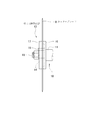
まず、図1および図2に基づき、路面加工機Aの基本構成を説明する。
1は車体であり、路面加工機に必要なエンジンや路面上を走行させる走行機構、路面加工時の粉塵を回収する集塵機構、切込み調整用の油圧機器などが搭載されている。これらの構造は公知の路面カッターと特に変ることはない。
Next, an embodiment of the present invention will be described with reference to the drawings.
First, the basic configuration of the road surface processing machine A will be described with reference to FIGS. 1 and 2.
車体1の下面には走行用の車輪2が取付けられている。また、切込み調整用の調整ローラ3がアーム4で支持され、車体1下面にピン5を介して取付けられている。
このアーム4がピン5を中心にして上げ下げすると、車体1の前方が上下するので、後述するカッターブレードBの切込み量を調整できる。アーム4の上下動は、図示しない油圧シリンダ等で行う。
A
When the arm 4 is raised and lowered with the pin 5 as the center, the front of the
図1および図2では、車体1の下面に取付けた切断用駆動軸10にカッターブレードBを取付けた状態を示している。また、カッターブレードBを囲むように集塵カバー6(点線図示)が取付けられるようになっている。集塵カバー6は路面切断により生じた粉塵の飛散を防止し、図示しないホースを介して、車体1内の集塵機構あるいは追随して走行する別体の集塵車に回収させるため設けられている。
FIGS. 1 and 2 show a state in which the cutter blade B is attached to the
車体1の下面には、図示の切断用駆動軸10や後述するグルーミング用駆動軸20を支持するための軸受7が2個取付けられている。この軸受7、7は、ボルトまたはナット8の締め戻しによって軸受7、7を車体1下面に着脱できるものである。
Two
つぎに、本発明の特徴部分を説明する。
本発明の特徴は、前記した2個一対の軸受7、7に1枚のカッターブレードを回転させる切断用駆動軸10と複数枚のグルーミングブレードを回転させるグルーミング用駆動軸20を選択的に支持させる構成とした点にある。
切断用駆動軸10とグルーミング用駆動軸20のそれぞれの構成は、つぎのとおりである。
Next, features of the present invention will be described.
A feature of the present invention is that the two pairs of
The respective configurations of the
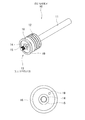
切断用駆動軸10を図3および図4に基づき説明する。
切断用駆動軸10は、一対の軸受7、7で支持される軸部11と、エンジンなどの回転駆動源からの駆動力を受けるプーリ12と、1枚のカッターブレードBを挾持する第1刃物取付部13を備えている。
The
The
軸部11は、軸受7、7で回転可能に支持される丸棒状の軸部材である。
プーリ12は、軸部11の適所に取付けられる。このプーリ12は、車体1内のエンジンの出力軸との間でベルト等が巻き掛けられて、回転トルクを軸部11に伝達するように構成されている。
The
The
第1刃物取付部13は、軸部11の一端部に形成されたカッターブレードBの取付部材である。
この第1刃物取付部13は、図3に示す軸部11の軸端に形成された小径軸部14と、この小径軸部14の先端部分に形成された雌ネジ部15と、小径軸部14に挿入される第1フランジ16を備えている。さらに図4に示す第2フランジ17と雌ネジ部15に螺合するナット18とを備えている。第1フランジ16は小径軸部14に対しロックピンやキー等の任意の手段で相互回転不能に拘束されている。
The first
The first
小径軸部14はカッターブレードBを1枚だけ取付けるものなので、短尺である。第1フランジ16の端面には、1本のピン19が植設されていて、第2フランジ17にはこのピン19を通す孔が形成されている。また、カッターブレードBには、小径軸部14に通す中心孔と、前記ピン19を通す孔(図示省略)が設けられている。
The small-
図4はカッターブレードBの取付状態を示している。
同図に示すように、小径軸部14に第1フランジ16を挿入し、ついでカッターブレードBを挿入し、最後に第2フランジ17を挿入してナット18で締め付けると、カッターブレードBが軸部11の第1刃物取付部13に取付けられる。
FIG. 4 shows a state in which the cutter blade B is attached.
As shown in the figure, when the
上記の状態で軸部11が回転すると、カッターブレードBはピン19によって第1フランジ16と共に回転するので、路面の縦切り切断が行える。
When the
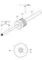
つぎに、グルーミング用駆動軸20を図5から図7に基づき説明する。
前記グルーミング用駆動軸20は、前記一対の軸受7、7で支持される軸部21と、エンジンからの駆動力を受けるプーリ22と、複数枚のグルーミングブレードCを並列に挾持する第2刃物取付部23を備えている。
Next, the
The
軸部21は、軸受7、7で回転可能に支持される丸棒状の軸部材である。
プーリ22は、軸部21の適所に取付けられる。このプーリ22は、車体1内のエンジンの出力軸との間でベルト等が巻き掛けられて、回転トルクを軸部21に伝達するように構成されている。
The
The
第2刃物取付部23は、軸部21の一端部に形成された複数枚のグルーミングブレードCの取付部材である。この第2刃物取付部23は、図5に示す軸部21の軸端に形成された小径軸部24と、この小径軸部24の先端部分に形成された雌ネジ部25と、小径軸部24に挿入される第1フランジ26を備えている。さらに図6に示す第2フランジ27を備えている。第1フランジ26および第2フランジ27は小径軸部24に対しロックピンやキー等の任意の手段で相互回転不能に拘束されている。
The second
小径軸部24は、グルーミングブレードCを複数枚取付けるものなので、長尺に形成されている。第1フランジ26と第2フランジ27との間には複数本の長尺のボルト31が通され固定できるようになっている。
図示の実施形態では、第2フランジ27の孔(図示省略)を通して第1フランジ26の端面にねじ込んでいるが、固定方法はこれに限ることなく、長尺のボルト31の端部をナットで固定してもよく、固定方法は任意である。また、図示の実施形態ではボルト31の本数は4本であるが、この本数も任意である。ボルト31を用いる目的は、複数枚のグルーミングブレードCを一体にたばねることと、軸部21と共に回転させることを保障する点にあるので、この目的を達成できる限り、本数や太さに制限はない。
The small-
In the illustrated embodiment, the screw is screwed into the end face of the
図7に示すように、小径軸部24に第1フランジ26を挿入し、ついで複数枚のグルーミングブレードCをカラー33を介在させて挿入し、最後に第2フランジ27を挿入してナット28で締め付けると、複数枚のグルーミングブレードCが軸部21の第1刃物取付部23に強固に取付けられる。なお、グルーミングブレードCとカラー33には、ボルト31を通す孔(図示省略)が形成されている。
As shown in FIG. 7, the
上記の状態で軸部21が回転すると、グルーミングブレードCはボルト31で拘束された状態で第1フランジ26と共に回転するので、路面上のグルーミング加工が行える。
When the
グルーミングブレードCの枚数は任意であり、図示の実施形態では8枚用いているが、7枚以下でもよく、9枚以上であってもよい。
グルーミングブレードCの取付け枚数が多い場合、図8に示すような小径軸部24の一端(図中左端)を支持する構造を付加してもよい。図示の支持構造は、小径軸部24の端部を軸受35を用いて支持するボス33を取付け、このボス33を支柱34で車体1に連結した構造であるが、この例に限らずグルーミング用駆動軸20をしっかり支えることができれば、どのような支持構造であってもよい。
The number of grooming blades C is arbitrary. In the illustrated embodiment, eight sheets are used. However, the number of grooming blades C may be seven or less, or nine or more.
When the number of attachments of the grooming blade C is large, a structure for supporting one end (the left end in the figure) of the small
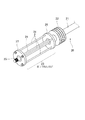
上記切断用駆動軸10の軸部11とグルーミング用駆動軸20の軸部21は、軸長と軸径は同一である。したがって、図1に示す一対の軸受7、7によって双方の駆動軸10、20を選択的に支持することができる。
The
図2は切断用駆動軸10を軸受7、7で支持している状態を示しているが、軸受7、7をいったん車体1から取り外し、軸部11から抜き、かつプーリ12に巻き掛けているベルトも外すと、切断用駆動軸10を車体1から取り外すことができる。そして、グルーミング用駆動軸20の軸部21に軸受7、7を挿入し、プーリ22にベルトを巻き掛けて、軸受7、7を車体1下面に取付けると、図8に示すようにグルーミング用駆動軸20を路面加工機Aに装備することができる。
上記組立分解を逆順で行うと、再び切断用駆動軸10を路面加工機Aに装備することができる。
FIG. 2 shows a state in which the cutting
When the assembly / disassembly is performed in the reverse order, the cutting
上記実施形態によれば、一対の軸受7、7に切断用駆動軸10を取付けた場合は、1枚のカッターブレードBを用いた路面の縦切り切削ができ、一対の軸受7、7にグルーミング用駆動軸20を取付けた場合は、複数枚のグルーミングブレードCで路面に複数条の滑り止め用溝を形成するグルーミング加工ができる。このように、駆動軸を選択して取付けることで、1台の加工機でありながら路面切断加工とグルーミング加工の両方を行うことができるので、比較的規模の小さな現場に便利であり、施工費用も安くできる。
According to the above embodiment, when the cutting
A 路面加工機
B カッターブレード
C グルーミングブレード
1 車体
2 車輪
3 調整ローラ
4 アーム
5 ピン
6 集塵カバー
7 軸受
10 切断用駆動軸
11 軸部
12 プーリ
13 第1刃物取付部
14 小径軸部
15 雌ネジ部
16 第1フランジ
17 第2フランジ
18 ナット
19 ピン
20 グルーミング用駆動軸
21 軸部
22 プーリ
23 第2刃物取付部
24 小径軸部
25 雌ネジ部
26 第1フランジ
27 第2フランジ
28 ナット
31 ボルト
A Road surface processing machine B Cutter blade
本発明は、路面加工機に関する。さらに詳しくは、路面の切削とグルービングを1台で行える路面加工機に関する。 The present invention relates to a road surface processing machine. More particularly, to the road processing machine capable of performing cutting and glue bi ring road at one.
道路や橋、空港の滑走路では古くなった舗装を剥がして新しく舗装をし直す補修工事が定期的に必要となる。古い舗装を取り除くには、いったん深さ20〜30cm位の縦切りを行い、ついで古い舗装を剥がし、新しい舗装を施工し、新路面が完成した後で、路面に滑り止めの浅溝を形成するグルービングを行う。 On roads, bridges, and airport runways, it is necessary to periodically perform repair work by removing old pavements and renewing them. To remove the old pavement, make a vertical cut of 20-30 cm in depth, then peel off the old pavement, construct a new pavement, and after the new road surface is completed, form a non-slip shallow groove on the road surface carry out the glue bi-ring.
前記の縦切り工事には、円板状のブレードにダイヤモンドチップを固着したカッターブレードを1枚用いて深く切り目を入れる路面カッターが使用される。また、グルービングには複数枚のダイヤモンドブレードを並べて取付けたグルービングブレードを用いて浅く切り目を入れるグルービング加工機が用いられる。 In the above-described vertical cutting work, a road surface cutter that uses a single cutter blade having a diamond tip fixed to a disk-shaped blade to make a deep cut is used. Also, the glue-bi packaging machine to put shallow cuts with a plurality glue bi ing blades mounted side by side diamond blade is used to glue bi ring.
路面カッターの代表的な構成は特許文献1にも示すとおりであり、車体の下面に走行用の車輪を備え、車体内に走行並びに切断用の駆動源としてのエンジンやモータ等を搭載している。車体下面にはカッター用の駆動軸が軸受によって取付けられ、その駆動軸の一端には1枚のカッターブレードを取付けている。このカッターブレードを回転させながら路面に深く切り込ませると、路面の縦切り切断が行える。
A typical configuration of a road surface cutter is as shown in
グルービング加工機の代表的な構成は特許文献2にも示すとおりであり、車体の下面に走行用の車輪を備え、車体内に走行並びに切断用の駆動源としてのエンジンやモータ等を搭載している。車体下面にはカッター用の駆動軸が軸受によって取付けられ、その駆動軸の一端には複数枚のグルービングブレードが取付けられている。このグルービングブレードを回転させながら路面に浅く切り込ませると、路面に複数条の滑り止め溝が形成される。
Typical configuration of the glue-bi packaging machine is as shown in
しかるに、これまで路面切断機もグルービング加工機も専用機しか存在しなかったので、舗装工事等を完成させるには、路面切断機の外にグルービング加工機も必要であった。規模が大きい舗装工事では二種の専用機を取り揃えることに支障はないが、規模が小さな舗装工事では専用機を二種揃えると施工費用が高くなったり、グルービング加工機を他の工事現場から搬送してくるのに時間がかかると工期が延びるという問題もあった。 However, so far because the only road cutting machine also glue bi-packaging machine also specialized machines did not exist, in order to complete the paving, etc., it was also required glue bi-packaging machine to the outside of the road cutting machine. Although there is no hindrance to equip of two special-purpose machine is a large pavement construction scale, or become high and construction cost align the special-purpose machine two in the scale is small pavement construction, the glue bi-packaging machine of other construction site There was also a problem that the construction period was extended if it took a long time to transport it.
しかるに、1台の加工機で路面の縦切り切削とグルービングが行えれば、施工費用も安く抑制でき、工期延長という問題もなくなる。 However, if one of the machines in the slitting cutting and glue bi-ring of the road surface is Okonaere, construction costs can also be cheaper suppression, also eliminated a problem that the construction period extension.
本発明は上記事情に鑑み、1台の加工機で路面の縦切り切断とグルービングの両方が行える路面加工機を提供することを目的とする。 In view of the above circumstances, and an object thereof is to provide a road processing machine capable of performing both slitting cut and glue bi ring road on one machine.
第1発明の路面加工機は、路面の縦切り切断および路面のグルービング加工を行う路面加工機であって、該路面加工機は、その車体内に回転駆動源を搭載し、その車体に切断用駆動軸とグルービング用駆動軸を選択的に支持する軸受を取付けており、前記切断用駆動軸は1枚のカッターブレードを回転させる駆動軸であり、前記グルービング用駆動軸は、複数枚のグルービングブレードを回転させる駆動軸であることを特徴とする。
第2発明の路面加工機は、第1発明において、前記切断用駆動軸は、車体に取付けられた前記軸受で支持される軸部と、該軸受に取付けられると共に前記回転駆動源からの駆動力を受けるプーリと、前記軸部の一端部において1枚のカッターブレードを挾持するよう構成された第1刃物取付部とを備えていることを特徴とする。
第3発明の路面加工機は、第1発明において、前記グルービング用駆動軸は、車体に取付けられた前記一対の軸受で支持される軸部と、前記回転駆動源からの駆動力を受けるプーリと、前記軸部の一端部において複数枚のグルービングブレードを並列に挾持するよう構成された第2刃物取付部を備えていることを特徴とする。
Road processing machine of the first invention is a road processing machine to perform slitting cut and glue bi ranging processing of the road surface of the road surface, road surface processing machine, equipped with a rotary driving source within the vehicle, its vehicle body and mounting a bearing for selectively supporting a drive shaft for the cutting drive shaft and the glue bi ring, the cutting drive shaft is a drive shaft for rotating a single cutter blade, said drive shaft for glue bi ring is characterized in that it is a drive shaft for rotating a plurality of glue bi ring blade.
The road surface processing machine according to a second aspect of the present invention is the road surface processing machine according to the first aspect, wherein the cutting drive shaft is supported by the bearing attached to the vehicle body, and is attached to the bearing and driven by the rotational drive source. And a first cutter attachment part configured to hold one cutter blade at one end of the shaft part.
Third road processing machine of the present invention, in the first invention, the drive shaft for glue bicycloalkyl ring receives a shaft portion supported by said pair of bearings mounted to the vehicle body, a driving force from the rotary drive source a pulley, characterized in that it comprises a second tool attachment portion configured to clamping a plurality of groups bicycloalkyl ring blade in parallel at one end of the shaft portion.
第1発明によれば、一対の軸受に切断用駆動軸を取付けた場合は、1枚のカッターブレードを用いた縦切り切断ができ、一対の軸受にグルービング用駆動軸を取付けた場合は、複数枚のグルービングブレードで路面に複数条の滑り止め用溝を形成するグルービング加工ができる。このように、駆動軸を選択して取付けることで、1台の加工機でありながら路面切断加工とグルービング加工の両方を行うことができるので、比較的規模の小さな現場に便利であり、施工費用も安くできる。
第2発明によれば、カッターブレードを第1刃物取付部に取付けて、切断用駆動軸の軸部を一対の軸受で車体に取付けると、1台の路面加工機を路面カッターとして使うことができる。
第3発明によれば、複数枚のグルービングブレードを第2刃物取付部に取付けて、グルービング用駆動軸の軸部を一対の軸受で車体に取付けると、1台の路面加工機をグルービング加工機として使うことができる。
According to the first invention, when fitted with a cutting drive shaft to the pair of bearings, it is slitting cleavage with one cutter blade, when fitted with the drive shaft for glue bicycloalkyl ring in a pair of bearings It can glue bi ranging processing for forming a non-slip grooves of plural rows on the road surface with a plurality of glue bi ring blade. In this manner, by attaching to select the drive shaft, it is possible to perform both the road cut and glue bi ing processed yet one machine, it is convenient to relatively scale small site, Construction costs can also be reduced.
According to the second invention, when the cutter blade is attached to the first blade attachment portion and the shaft portion of the cutting drive shaft is attached to the vehicle body with the pair of bearings, one road surface processing machine can be used as a road surface cutter. .
According to the third invention, by attaching a plurality of glue bi ring blade to the second blade mounting portion, when attached to the vehicle body the shaft of the glue bi ring drive shaft by a pair of bearings, the one of the road processing machine it can be used as a glue bi-packaging machine.
つぎに、本発明の実施形態を図面に基づき説明する。
まず、図1および図2に基づき、路面加工機Aの基本構成を説明する。
1は車体であり、路面加工機に必要なエンジンや路面上を走行させる走行機構、路面加工時の粉塵を回収する集塵機構、切込み調整用の油圧機器などが搭載されている。これらの構造は公知の路面カッターと特に変ることはない。
Next, an embodiment of the present invention will be described with reference to the drawings.
First, the basic configuration of the road surface processing machine A will be described with reference to FIGS. 1 and 2.
車体1の下面には走行用の車輪2が取付けられている。また、切込み調整用の調整ローラ3がアーム4で支持され、車体1下面にピン5を介して取付けられている。
このアーム4がピン5を中心にして上げ下げすると、車体1の前方が上下するので、後述するカッターブレードBの切込み量を調整できる。アーム4の上下動は、図示しない油圧シリンダ等で行う。
A traveling
When the arm 4 is raised and lowered with the pin 5 as the center, the front of the
図1および図2では、車体1の下面に取付けた切断用駆動軸10にカッターブレードBを取付けた状態を示している。また、カッターブレードBを囲むように集塵カバー6(点線図示)が取付けられるようになっている。集塵カバー6は路面切断により生じた粉塵の飛散を防止し、図示しないホースを介して、車体1内の集塵機構あるいは追随して走行する別体の集塵車に回収させるため設けられている。
FIGS. 1 and 2 show a state in which the cutter blade B is attached to the cutting
車体1の下面には、図示の切断用駆動軸10や後述するグルービング用駆動軸20を支持するための軸受7が2個取付けられている。この軸受7、7は、ボルトまたはナット8の締め戻しによって軸受7、7を車体1下面に着脱できるものである。
The lower surface of the
つぎに、本発明の特徴部分を説明する。
本発明の特徴は、前記した2個一対の軸受7、7に1枚のカッターブレードを回転させる切断用駆動軸10と複数枚のグルービングブレードを回転させるグルービング用駆動軸20を選択的に支持させる構成とした点にある。
切断用駆動軸10とグルービング用駆動軸20のそれぞれの構成は、つぎのとおりである。
Next, features of the present invention will be described.
Feature of the present invention, selects a pair of two
Each configuration of the cutting
切断用駆動軸10を図3および図4に基づき説明する。
切断用駆動軸10は、一対の軸受7、7で支持される軸部11と、エンジンなどの回転駆動源からの駆動力を受けるプーリ12と、1枚のカッターブレードBを挾持する第1刃物取付部13を備えている。
The cutting
The cutting
軸部11は、軸受7、7で回転可能に支持される丸棒状の軸部材である。
プーリ12は、軸部11の適所に取付けられる。このプーリ12は、車体1内のエンジンの出力軸との間でベルト等が巻き掛けられて、回転トルクを軸部11に伝達するように構成されている。
The
The
第1刃物取付部13は、軸部11の一端部に形成されたカッターブレードBの取付部材である。
この第1刃物取付部13は、図3に示す軸部11の軸端に形成された小径軸部14と、この小径軸部14の先端部分に形成された雌ネジ部15と、小径軸部14に挿入される第1フランジ16を備えている。さらに図4に示す第2フランジ17と雌ネジ部15に螺合するナット18とを備えている。第1フランジ16は小径軸部14に対しロックピンやキー等の任意の手段で相互回転不能に拘束されている。
The first
The first
小径軸部14はカッターブレードBを1枚だけ取付けるものなので、短尺である。第1フランジ16の端面には、1本のピン19が植設されていて、第2フランジ17にはこのピン19を通す孔が形成されている。また、カッターブレードBには、小径軸部14に通す中心孔と、前記ピン19を通す孔(図示省略)が設けられている。
The small-
図4はカッターブレードBの取付状態を示している。
同図に示すように、小径軸部14に第1フランジ16を挿入し、ついでカッターブレードBを挿入し、最後に第2フランジ17を挿入してナット18で締め付けると、カッターブレードBが軸部11の第1刃物取付部13に取付けられる。
FIG. 4 shows a state in which the cutter blade B is attached.
As shown in the figure, when the
上記の状態で軸部11が回転すると、カッターブレードBはピン19によって第1フランジ16と共に回転するので、路面の縦切り切断が行える。
When the
つぎに、グルービング用駆動軸20を図5から図7に基づき説明する。
前記グルービング用駆動軸20は、前記一対の軸受7、7で支持される軸部21と、エンジンからの駆動力を受けるプーリ22と、複数枚のグルービングブレードCを並列に挾持する第2刃物取付部23を備えている。
It will now be described on the basis of the glue bi
The glue bi
軸部21は、軸受7、7で回転可能に支持される丸棒状の軸部材である。
プーリ22は、軸部21の適所に取付けられる。このプーリ22は、車体1内のエンジンの出力軸との間でベルト等が巻き掛けられて、回転トルクを軸部21に伝達するように構成されている。
The
The
第2刃物取付部23は、軸部21の一端部に形成された複数枚のグルービングブレードCの取付部材である。この第2刃物取付部23は、図5に示す軸部21の軸端に形成された小径軸部24と、この小径軸部24の先端部分に形成された雌ネジ部25と、小径軸部24に挿入される第1フランジ26を備えている。さらに図6に示す第2フランジ27を備えている。第1フランジ26および第2フランジ27は小径軸部24に対しロックピンやキー等の任意の手段で相互回転不能に拘束されている。
Second
小径軸部24は、グルービングブレードCを複数枚取付けるものなので、長尺に形成されている。第1フランジ26と第2フランジ27との間には複数本の長尺のボルト31が通され固定できるようになっている。
図示の実施形態では、第2フランジ27の孔(図示省略)を通して第1フランジ26の端面にねじ込んでいるが、固定方法はこれに限ることなく、長尺のボルト31の端部をナットで固定してもよく、固定方法は任意である。また、図示の実施形態ではボルト31の本数は4本であるが、この本数も任意である。ボルト31を用いる目的は、複数枚のグルービングブレードCを一体にたばねることと、軸部21と共に回転させることを保障する点にあるので、この目的を達成できる限り、本数や太さに制限はない。
Small-
In the illustrated embodiment, the screw is screwed into the end face of the
図7に示すように、小径軸部24に第1フランジ26を挿入し、ついで複数枚のグルービングブレードCをカラー33を介在させて挿入し、最後に第2フランジ27を挿入してナット28で締め付けると、複数枚のグルービングブレードCが軸部21の第1刃物取付部23に強固に取付けられる。なお、グルービングブレードCとカラー33には、ボルト31を通す孔(図示省略)が形成されている。
As shown in FIG. 7, by inserting the
上記の状態で軸部21が回転すると、グルービングブレードCはボルト31で拘束された状態で第1フランジ26と共に回転するので、路面上のグルービング加工が行える。
When the
グルービングブレードCの枚数は任意であり、図示の実施形態では8枚用いているが、7枚以下でもよく、9枚以上であってもよい。
グルービングブレードCの取付け枚数が多い場合、図8に示すような小径軸部24の一端(図中左端)を支持する構造を付加してもよい。図示の支持構造は、小径軸部24の端部を軸受35を用いて支持するボス33を取付け、このボス33を支柱34で車体1に連結した構造であるが、この例に限らずグルービング用駆動軸20をしっかり支えることができれば、どのような支持構造であってもよい。
Glue bi ring blade count of C is optional, is used eight in the illustrated embodiment, it may be a seven or less, or may be nine or more.
When mounting the number of glue bi ring blade C is large, may be added structure for supporting one end (left end in the drawing) of the small
上記切断用駆動軸10の軸部11とグルービング用駆動軸20の軸部21は、軸長と軸径は同一である。したがって、図1に示す一対の軸受7、7によって双方の駆動軸10、20を選択的に支持することができる。
図2は切断用駆動軸10を軸受7、7で支持している状態を示しているが、軸受7、7をいったん車体1から取り外し、軸部11から抜き、かつプーリ12に巻き掛けているベルトも外すと、切断用駆動軸10を車体1から取り外すことができる。そして、グルービング用駆動軸20の軸部21に軸受7、7を挿入し、プーリ22にベルトを巻き掛けて、軸受7、7を車体1下面に取付けると、図8に示すようにグルービング用駆動軸20を路面加工機Aに装備することができる。
上記組立分解を逆順で行うと、再び切断用駆動軸10を路面加工機Aに装備することができる。
FIG. 2 shows a state in which the cutting
When the assembly / disassembly is performed in the reverse order, the cutting
上記実施形態によれば、一対の軸受7、7に切断用駆動軸10を取付けた場合は、1枚のカッターブレードBを用いた路面の縦切り切削ができ、一対の軸受7、7にグルービング用駆動軸20を取付けた場合は、複数枚のグルービングブレードCで路面に複数条の滑り止め用溝を形成するグルービング加工ができる。このように、駆動軸を選択して取付けることで、1台の加工機でありながら路面切断加工とグルービング加工の両方を行うことができるので、比較的規模の小さな現場に便利であり、施工費用も安くできる。
According to the above embodiment, when the cutting
A 路面加工機
B カッターブレード
C グルービングブレード
1 車体
2 車輪
3 調整ローラ
4 アーム
5 ピン
6 集塵カバー
7 軸受
10 切断用駆動軸
11 軸部
12 プーリ
13 第1刃物取付部
14 小径軸部
15 雌ネジ部
16 第1フランジ
17 第2フランジ
18 ナット
19 ピン
20 グルービング用駆動軸
21 軸部
22 プーリ
23 第2刃物取付部
24 小径軸部
25 雌ネジ部
26 第1フランジ
27 第2フランジ
28 ナット
31 ボルト
A road machine B cutter blade C glue
第1発明の路面加工機は、路面の縦切り切断および路面のグルービング加工を行う路面加工機であって、該路面加工機は、その車体内に回転駆動源を搭載し、その車体に切断用駆動軸とグルービング用駆動軸を選択的に支持する軸受を取付けており、前記切断用駆動軸は1枚のカッターブレードを回転させる駆動軸であり、前記グルービング用駆動軸は、複数枚のグルービングブレードを回転させる駆動軸であり、前記切断用駆動軸は、車体に取付けられた前記軸受で支持される軸部と、該軸受に取付けられると共に前記回転駆動源からの駆動力を受けるプーリと、前記軸部の一端部において1枚のカッターブレードを挾持するよう構成された第1刃物取付部とを備えており、前記軸部、前記プーリ、および前記第1刃物取付部がこの順に配置されていることを特徴とする。
第2発明の路面加工機は、路面の縦切り切断および路面のグルービング加工を行う路面加工機であって、該路面加工機は、その車体内に回転駆動源を搭載し、その車体に切断用駆動軸とグルービング用駆動軸を選択的に支持する軸受を取付けており、前記切断用駆動軸は1枚のカッターブレードを回転させる駆動軸であり、前記グルービング用駆動軸は、複数枚のグルービングブレードを回転させる駆動軸であり、前記グルービング用駆動軸は、車体に取付けられた前記一対の軸受で支持される軸部と、前記回転駆動源からの駆動力を受けるプーリと、前記軸部の一端部において複数枚のグルービングブレードを並列に挾持するよう構成された第2刃物取付部を備えており、前記軸部、前記プーリ、および前記第2刃物取付部がこの順に配置されていることを特徴とする。
A road surface processing machine according to a first aspect of the present invention is a road surface processing machine that performs longitudinal cutting of a road surface and grooving processing of the road surface, and the road surface processing machine has a rotational drive source mounted in the vehicle body and is used for cutting in the vehicle body. A bearing that selectively supports a drive shaft and a grooving drive shaft is attached, the cutting drive shaft is a drive shaft that rotates one cutter blade, and the grooving drive shaft is a plurality of grooving blades drive shaft der for rotating is, the cutting drive shaft includes a shaft portion supported by the bearing which is attached to the vehicle body, a pulley which receives the driving force from the rotation driving source with mounted on the bearing, A first blade attachment portion configured to hold one cutter blade at one end of the shaft portion, and the shaft portion, the pulley, and the first blade attachment portion are arranged in this order. Characterized in that it is.
A road surface processing machine according to a second aspect of the invention is a road surface processing machine that performs longitudinal cutting of a road surface and grooving of the road surface, and the road surface processing machine is equipped with a rotational drive source in the vehicle body and is used for cutting the vehicle body. A bearing that selectively supports a drive shaft and a grooving drive shaft is attached, the cutting drive shaft is a drive shaft that rotates one cutter blade, and the grooving drive shaft is a plurality of grooving blades The grooving drive shaft includes a shaft portion supported by the pair of bearings attached to a vehicle body, a pulley that receives a driving force from the rotational drive source, and one end of the shaft portion. A second blade attachment portion configured to hold a plurality of grooving blades in parallel at the portion, and the shaft portion, the pulley, and the second blade attachment portion are arranged in this order. It is characterized in that is.
第1発明によれば、一対の軸受に切断用駆動軸を取付けた場合は、1枚のカッターブレードを用いた縦切り切断ができ、一対の軸受にグルービング用駆動軸を取付けた場合は、複数枚のグルービングブレードで路面に複数条の滑り止め用溝を形成するグルービング加工ができる。このように、駆動軸を選択して取付けることで、1台の加工機でありながら路面切断加工とグルービング加工の両方を行うことができるので、比較的規模の小さな現場に便利であり、施工費用も安くできる。
また、カッターブレードを第1刃物取付部に取付けて、切断用駆動軸の軸部を一対の軸受で車体に取付けると、1台の路面加工機を路面カッターとして使うことができる。
第2発明によれば、一対の軸受に切断用駆動軸を取付けた場合は、1枚のカッターブレードを用いた縦切り切断ができ、一対の軸受にグルービング用駆動軸を取付けた場合は、複数枚のグルービングブレードで路面に複数条の滑り止め用溝を形成するグルービング加工ができる。このように、駆動軸を選択して取付けることで、1台の加工機でありながら路面切断加工とグルービング加工の両方を行うことができるので、比較的規模の小さな現場に便利であり、施工費用も安くできる。
また、複数枚のグルービングブレードを第2刃物取付部に取付けて、グルービング用駆動軸の軸部を一対の軸受で車体に取付けると、1台の路面加工機をグルービング加工機として使うことができる。
According to the first invention, when the cutting drive shaft is attached to a pair of bearings, longitudinal cutting using one cutter blade can be performed, and when the grooving drive shaft is attached to a pair of bearings, a plurality of Grooving can be performed by forming a plurality of anti-slip grooves on the road surface with a single grooving blade. In this way, by selecting and mounting the drive shaft, it is possible to perform both road cutting and grooving while being a single processing machine, which is convenient for relatively small sites and construction costs. Can also be cheap.
Further, when the cutter blade is attached to the first blade attachment portion and the shaft portion of the cutting drive shaft is attached to the vehicle body with a pair of bearings, one road surface processing machine can be used as a road surface cutter.
According to the second invention, when the cutting drive shaft is attached to a pair of bearings, longitudinal cutting using one cutter blade can be performed, and when the grooving drive shaft is attached to a pair of bearings, a plurality of Grooving can be performed by forming a plurality of anti-slip grooves on the road surface with a single grooving blade. In this way, by selecting and mounting the drive shaft, it is possible to perform both road cutting and grooving while being a single processing machine, which is convenient for relatively small sites and construction costs. Can also be cheap.
Further, when a plurality of grooving blades are attached to the second blade attachment portion and the shaft portion of the grooving drive shaft is attached to the vehicle body with a pair of bearings, one road surface processing machine can be used as the grooving machine.
Claims (3)
該路面加工機は、その車体内に回転駆動源を搭載し、その車体に切断用駆動軸とグルーミング用駆動軸を選択的に支持する軸受を取付けており、
前記切断用駆動軸は1枚のカッターブレードを回転させる駆動軸であり、
前記グルーミング用駆動軸は、複数枚のグルーミングブレードを回転させる駆動軸である
ことを特徴とする路面加工機。 A road surface processing machine that performs longitudinal cutting of a road surface and grooming of the road surface,
The road surface processing machine has a rotational drive source mounted in the vehicle body, and a bearing that selectively supports the cutting drive shaft and the grooming drive shaft is attached to the vehicle body.
The cutting drive shaft is a drive shaft for rotating one cutter blade,
The road surface processing machine, wherein the grooming drive shaft is a drive shaft for rotating a plurality of grooming blades.
ことを特徴とする請求項1記載の路面加工機。 The cutting drive shaft includes a shaft portion supported by the bearing attached to the vehicle body, a pulley attached to the bearing and receiving a driving force from the rotational drive source, and one piece at one end of the shaft portion. The road surface processing machine according to claim 1, further comprising a first blade attachment portion configured to hold the cutter blade.
ことを特徴とする請求項1記載の路面加工機。 The grooming drive shaft includes a shaft portion supported by the pair of bearings attached to a vehicle body, a pulley that receives a driving force from the rotational drive source, and a plurality of grooming blades at one end of the shaft portion. The road surface processing machine according to claim 1, further comprising a second blade attachment portion configured to be held in parallel.
Priority Applications (1)
| Application Number | Priority Date | Filing Date | Title |
|---|---|---|---|
| JP2016078617A JP6175533B1 (en) | 2016-04-11 | 2016-04-11 | Road surface processing machine |
Applications Claiming Priority (1)
| Application Number | Priority Date | Filing Date | Title |
|---|---|---|---|
| JP2016078617A JP6175533B1 (en) | 2016-04-11 | 2016-04-11 | Road surface processing machine |
Publications (2)
| Publication Number | Publication Date |
|---|---|
| JP6175533B1 JP6175533B1 (en) | 2017-08-02 |
| JP2017190562A true JP2017190562A (en) | 2017-10-19 |
Family
ID=59505223
Family Applications (1)
| Application Number | Title | Priority Date | Filing Date |
|---|---|---|---|
| JP2016078617A Active JP6175533B1 (en) | 2016-04-11 | 2016-04-11 | Road surface processing machine |
Country Status (1)
| Country | Link |
|---|---|
| JP (1) | JP6175533B1 (en) |
Cited By (1)
| Publication number | Priority date | Publication date | Assignee | Title |
|---|---|---|---|---|
| JP2019157389A (en) * | 2018-03-08 | 2019-09-19 | 大林道路株式会社 | Double loading cutter |
Families Citing this family (1)
| Publication number | Priority date | Publication date | Assignee | Title |
|---|---|---|---|---|
| CN112239982B (en) * | 2020-10-28 | 2022-02-08 | 杭州成邦沥青混凝土有限公司 | Asphalt pavement repairing method |
Citations (7)
| Publication number | Priority date | Publication date | Assignee | Title |
|---|---|---|---|---|
| JPS6063637U (en) * | 1983-10-07 | 1985-05-04 | 鋼弦器材株式会社 | Concrete cutter for flooring using an expansive breaking agent |
| JPH10280315A (en) * | 1997-03-31 | 1998-10-20 | Nippon Fureki Sangyo Kk | Dry processing device for road face |
| JP3081428U (en) * | 2001-04-26 | 2001-11-02 | 武林工業株式会社 | Concrete cutter used for joint repair method of concrete at steel tower site |
| JP2003313810A (en) * | 2002-04-22 | 2003-11-06 | ▲蔦▼井株式会社 | Road cutting multi-wheel |
| JP2005188178A (en) * | 2003-12-26 | 2005-07-14 | Shiga Sangyo Kk | Road surface cutter |
| JP2012002024A (en) * | 2010-06-18 | 2012-01-05 | Nakayama Tekko Kk | Cutter blade cooling mechanism and paving material cutting device with the same |
| JP2016205003A (en) * | 2015-04-23 | 2016-12-08 | 仲山鉄工株式会社 | Cutting dust collection method and device in pavement material cutting device and pavement material cutting device equipped with the same |
-
2016
- 2016-04-11 JP JP2016078617A patent/JP6175533B1/en active Active
Patent Citations (7)
| Publication number | Priority date | Publication date | Assignee | Title |
|---|---|---|---|---|
| JPS6063637U (en) * | 1983-10-07 | 1985-05-04 | 鋼弦器材株式会社 | Concrete cutter for flooring using an expansive breaking agent |
| JPH10280315A (en) * | 1997-03-31 | 1998-10-20 | Nippon Fureki Sangyo Kk | Dry processing device for road face |
| JP3081428U (en) * | 2001-04-26 | 2001-11-02 | 武林工業株式会社 | Concrete cutter used for joint repair method of concrete at steel tower site |
| JP2003313810A (en) * | 2002-04-22 | 2003-11-06 | ▲蔦▼井株式会社 | Road cutting multi-wheel |
| JP2005188178A (en) * | 2003-12-26 | 2005-07-14 | Shiga Sangyo Kk | Road surface cutter |
| JP2012002024A (en) * | 2010-06-18 | 2012-01-05 | Nakayama Tekko Kk | Cutter blade cooling mechanism and paving material cutting device with the same |
| JP2016205003A (en) * | 2015-04-23 | 2016-12-08 | 仲山鉄工株式会社 | Cutting dust collection method and device in pavement material cutting device and pavement material cutting device equipped with the same |
Cited By (2)
| Publication number | Priority date | Publication date | Assignee | Title |
|---|---|---|---|---|
| JP2019157389A (en) * | 2018-03-08 | 2019-09-19 | 大林道路株式会社 | Double loading cutter |
| JP7018333B2 (en) | 2018-03-08 | 2022-02-10 | 大林道路株式会社 | Double cutter |
Also Published As
| Publication number | Publication date |
|---|---|
| JP6175533B1 (en) | 2017-08-02 |
Similar Documents
| Publication | Publication Date | Title |
|---|---|---|
| CN1265950C (en) | Tool unit cutting or sawing machine and method for cutting or sawing | |
| US20130319201A1 (en) | Cutting chain for cutting mineral and metal materials | |
| JP6175533B1 (en) | Road surface processing machine | |
| US20150330037A1 (en) | Method of grinding a two-lane roadway in two passes | |
| US9376776B2 (en) | High-production routing device | |
| IL33935A (en) | Apparatus for treating or digging into surfaces and cutting members for this apparatus | |
| US8215867B2 (en) | Trench compacting apparatus | |
| US11639592B2 (en) | Spacer structure for a saw disc assembly and a saw disc assembly | |
| CN202073019U (en) | Lightweight pavement grooving machine | |
| CN108779611A (en) | Locking system for preventing cutter holder from rotating | |
| CN219490625U (en) | Duplex chisel device | |
| CN104480890A (en) | Hand-push type power drive steel brush de-icing machine | |
| KR20210055966A (en) | Grooving construction device for road surface | |
| JP3246613U (en) | Cutter device | |
| CN105625251A (en) | Deicing and snow removing device | |
| KR101738355B1 (en) | a power transmitting appartus with changeable multi joint | |
| KR20180105521A (en) | Cutting Machin For Pavement | |
| JP4011199B2 (en) | Pavement cutting machine and curved inclined surface cutting method | |
| RU117459U1 (en) | DEVICE FOR CROSSING ICE ON ROAD COVERING | |
| CN104074219A (en) | Soil cleaning machine of groove sawing machine | |
| JP4108636B2 (en) | Rotating body for blade installation of human drill lid frame removal method and human hole lid frame replacement method | |
| JP2023503468A (en) | floor cutting machine | |
| CN110557984A (en) | Agricultural weeding device | |
| EP3128126A1 (en) | Cutting drum with pivot cutter unit | |
| JP2020137506A (en) | Blower for bush cutter |
Legal Events
| Date | Code | Title | Description |
|---|---|---|---|
| A521 | Request for written amendment filed |
Free format text: JAPANESE INTERMEDIATE CODE: A523 Effective date: 20170606 |
|
| TRDD | Decision of grant or rejection written | ||
| A01 | Written decision to grant a patent or to grant a registration (utility model) |
Free format text: JAPANESE INTERMEDIATE CODE: A01 Effective date: 20170627 |
|
| A61 | First payment of annual fees (during grant procedure) |
Free format text: JAPANESE INTERMEDIATE CODE: A61 Effective date: 20170710 |
|
| R150 | Certificate of patent or registration of utility model |
Ref document number: 6175533 Country of ref document: JP Free format text: JAPANESE INTERMEDIATE CODE: R150 |
|
| R250 | Receipt of annual fees |
Free format text: JAPANESE INTERMEDIATE CODE: R250 |
|
| R250 | Receipt of annual fees |
Free format text: JAPANESE INTERMEDIATE CODE: R250 |