JP2017190130A - Shear band and non-pneumatic tire - Google Patents
Shear band and non-pneumatic tire Download PDFInfo
- Publication number
- JP2017190130A JP2017190130A JP2017076191A JP2017076191A JP2017190130A JP 2017190130 A JP2017190130 A JP 2017190130A JP 2017076191 A JP2017076191 A JP 2017076191A JP 2017076191 A JP2017076191 A JP 2017076191A JP 2017190130 A JP2017190130 A JP 2017190130A
- Authority
- JP
- Japan
- Prior art keywords
- shear band
- layer
- spacer structure
- reinforcing
- shear
- Prior art date
- Legal status (The legal status is an assumption and is not a legal conclusion. Google has not performed a legal analysis and makes no representation as to the accuracy of the status listed.)
- Pending
Links
- 125000006850 spacer group Chemical group 0.000 claims abstract description 77
- 239000000463 material Substances 0.000 claims abstract description 48
- 239000012528 membrane Substances 0.000 claims abstract description 29
- 230000003014 reinforcing effect Effects 0.000 claims description 105
- 230000002787 reinforcement Effects 0.000 abstract description 17
- 230000020169 heat generation Effects 0.000 abstract description 2
- 239000004744 fabric Substances 0.000 description 58
- 229920001971 elastomer Polymers 0.000 description 11
- 239000000835 fiber Substances 0.000 description 7
- 238000005452 bending Methods 0.000 description 6
- 230000006835 compression Effects 0.000 description 5
- 238000007906 compression Methods 0.000 description 5
- 229910000831 Steel Inorganic materials 0.000 description 4
- 239000000853 adhesive Substances 0.000 description 4
- 230000001070 adhesive effect Effects 0.000 description 4
- 239000010959 steel Substances 0.000 description 4
- 238000012360 testing method Methods 0.000 description 4
- 238000013461 design Methods 0.000 description 3
- 229920000126 latex Polymers 0.000 description 3
- DGXAGETVRDOQFP-UHFFFAOYSA-N 2,6-dihydroxybenzaldehyde Chemical compound OC1=CC=CC(O)=C1C=O DGXAGETVRDOQFP-UHFFFAOYSA-N 0.000 description 2
- KAKZBPTYRLMSJV-UHFFFAOYSA-N Butadiene Chemical compound C=CC=C KAKZBPTYRLMSJV-UHFFFAOYSA-N 0.000 description 2
- PPBRXRYQALVLMV-UHFFFAOYSA-N Styrene Chemical compound C=CC1=CC=CC=C1 PPBRXRYQALVLMV-UHFFFAOYSA-N 0.000 description 2
- 239000004816 latex Substances 0.000 description 2
- 238000005259 measurement Methods 0.000 description 2
- 239000011347 resin Substances 0.000 description 2
- 229920005989 resin Polymers 0.000 description 2
- 239000004753 textile Substances 0.000 description 2
- 229920002725 thermoplastic elastomer Polymers 0.000 description 2
- 239000013638 trimer Substances 0.000 description 2
- 238000009941 weaving Methods 0.000 description 2
- 239000002759 woven fabric Substances 0.000 description 2
- 229920013489 Arnitel® PL420-H Polymers 0.000 description 1
- 229920011484 Arnitel® PL461 Polymers 0.000 description 1
- 229920002748 Basalt fiber Polymers 0.000 description 1
- 229910001369 Brass Inorganic materials 0.000 description 1
- 229920000049 Carbon (fiber) Polymers 0.000 description 1
- 239000004677 Nylon Substances 0.000 description 1
- 239000002318 adhesion promoter Substances 0.000 description 1
- 239000004760 aramid Substances 0.000 description 1
- 229920003235 aromatic polyamide Polymers 0.000 description 1
- 239000010951 brass Substances 0.000 description 1
- 239000004917 carbon fiber Substances 0.000 description 1
- 150000001875 compounds Chemical class 0.000 description 1
- 238000010276 construction Methods 0.000 description 1
- 238000010586 diagram Methods 0.000 description 1
- 239000013013 elastic material Substances 0.000 description 1
- 239000000806 elastomer Substances 0.000 description 1
- 239000003365 glass fiber Substances 0.000 description 1
- 230000009477 glass transition Effects 0.000 description 1
- 238000012423 maintenance Methods 0.000 description 1
- 239000002184 metal Substances 0.000 description 1
- VNWKTOKETHGBQD-UHFFFAOYSA-N methane Chemical compound C VNWKTOKETHGBQD-UHFFFAOYSA-N 0.000 description 1
- 239000000203 mixture Substances 0.000 description 1
- 238000012544 monitoring process Methods 0.000 description 1
- 229920001778 nylon Polymers 0.000 description 1
- 238000013001 point bending Methods 0.000 description 1
- 229920000728 polyester Polymers 0.000 description 1
- 239000007787 solid Substances 0.000 description 1
- 238000007655 standard test method Methods 0.000 description 1
- 239000000126 substance Substances 0.000 description 1
- 238000010998 test method Methods 0.000 description 1
- 230000000007 visual effect Effects 0.000 description 1
Images


Classifications
-
- B—PERFORMING OPERATIONS; TRANSPORTING
- B60—VEHICLES IN GENERAL
- B60C—VEHICLE TYRES; TYRE INFLATION; TYRE CHANGING; CONNECTING VALVES TO INFLATABLE ELASTIC BODIES IN GENERAL; DEVICES OR ARRANGEMENTS RELATED TO TYRES
- B60C7/00—Non-inflatable or solid tyres
- B60C7/10—Non-inflatable or solid tyres characterised by means for increasing resiliency
- B60C7/102—Tyres built-up with separate rubber parts
-
- B—PERFORMING OPERATIONS; TRANSPORTING
- B60—VEHICLES IN GENERAL
- B60C—VEHICLE TYRES; TYRE INFLATION; TYRE CHANGING; CONNECTING VALVES TO INFLATABLE ELASTIC BODIES IN GENERAL; DEVICES OR ARRANGEMENTS RELATED TO TYRES
- B60C7/00—Non-inflatable or solid tyres
- B60C7/10—Non-inflatable or solid tyres characterised by means for increasing resiliency
- B60C7/107—Non-inflatable or solid tyres characterised by means for increasing resiliency comprising lateral openings
-
- B—PERFORMING OPERATIONS; TRANSPORTING
- B60—VEHICLES IN GENERAL
- B60C—VEHICLE TYRES; TYRE INFLATION; TYRE CHANGING; CONNECTING VALVES TO INFLATABLE ELASTIC BODIES IN GENERAL; DEVICES OR ARRANGEMENTS RELATED TO TYRES
- B60C7/00—Non-inflatable or solid tyres
-
- B—PERFORMING OPERATIONS; TRANSPORTING
- B32—LAYERED PRODUCTS
- B32B—LAYERED PRODUCTS, i.e. PRODUCTS BUILT-UP OF STRATA OF FLAT OR NON-FLAT, e.g. CELLULAR OR HONEYCOMB, FORM
- B32B25/00—Layered products comprising a layer of natural or synthetic rubber
- B32B25/10—Layered products comprising a layer of natural or synthetic rubber next to a fibrous or filamentary layer
-
- B—PERFORMING OPERATIONS; TRANSPORTING
- B32—LAYERED PRODUCTS
- B32B—LAYERED PRODUCTS, i.e. PRODUCTS BUILT-UP OF STRATA OF FLAT OR NON-FLAT, e.g. CELLULAR OR HONEYCOMB, FORM
- B32B25/00—Layered products comprising a layer of natural or synthetic rubber
- B32B25/12—Layered products comprising a layer of natural or synthetic rubber comprising natural rubber
-
- B—PERFORMING OPERATIONS; TRANSPORTING
- B32—LAYERED PRODUCTS
- B32B—LAYERED PRODUCTS, i.e. PRODUCTS BUILT-UP OF STRATA OF FLAT OR NON-FLAT, e.g. CELLULAR OR HONEYCOMB, FORM
- B32B3/00—Layered products comprising a layer with external or internal discontinuities or unevennesses, or a layer of non-planar shape; Layered products comprising a layer having particular features of form
- B32B3/10—Layered products comprising a layer with external or internal discontinuities or unevennesses, or a layer of non-planar shape; Layered products comprising a layer having particular features of form characterised by a discontinuous layer, i.e. formed of separate pieces of material
- B32B3/12—Layered products comprising a layer with external or internal discontinuities or unevennesses, or a layer of non-planar shape; Layered products comprising a layer having particular features of form characterised by a discontinuous layer, i.e. formed of separate pieces of material characterised by a layer of regularly- arranged cells, e.g. a honeycomb structure
-
- B—PERFORMING OPERATIONS; TRANSPORTING
- B32—LAYERED PRODUCTS
- B32B—LAYERED PRODUCTS, i.e. PRODUCTS BUILT-UP OF STRATA OF FLAT OR NON-FLAT, e.g. CELLULAR OR HONEYCOMB, FORM
- B32B5/00—Layered products characterised by the non- homogeneity or physical structure, i.e. comprising a fibrous, filamentary, particulate or foam layer; Layered products characterised by having a layer differing constitutionally or physically in different parts
- B32B5/02—Layered products characterised by the non- homogeneity or physical structure, i.e. comprising a fibrous, filamentary, particulate or foam layer; Layered products characterised by having a layer differing constitutionally or physically in different parts characterised by structural features of a fibrous or filamentary layer
- B32B5/022—Non-woven fabric
-
- B—PERFORMING OPERATIONS; TRANSPORTING
- B32—LAYERED PRODUCTS
- B32B—LAYERED PRODUCTS, i.e. PRODUCTS BUILT-UP OF STRATA OF FLAT OR NON-FLAT, e.g. CELLULAR OR HONEYCOMB, FORM
- B32B5/00—Layered products characterised by the non- homogeneity or physical structure, i.e. comprising a fibrous, filamentary, particulate or foam layer; Layered products characterised by having a layer differing constitutionally or physically in different parts
- B32B5/02—Layered products characterised by the non- homogeneity or physical structure, i.e. comprising a fibrous, filamentary, particulate or foam layer; Layered products characterised by having a layer differing constitutionally or physically in different parts characterised by structural features of a fibrous or filamentary layer
- B32B5/024—Woven fabric
-
- B—PERFORMING OPERATIONS; TRANSPORTING
- B32—LAYERED PRODUCTS
- B32B—LAYERED PRODUCTS, i.e. PRODUCTS BUILT-UP OF STRATA OF FLAT OR NON-FLAT, e.g. CELLULAR OR HONEYCOMB, FORM
- B32B5/00—Layered products characterised by the non- homogeneity or physical structure, i.e. comprising a fibrous, filamentary, particulate or foam layer; Layered products characterised by having a layer differing constitutionally or physically in different parts
- B32B5/02—Layered products characterised by the non- homogeneity or physical structure, i.e. comprising a fibrous, filamentary, particulate or foam layer; Layered products characterised by having a layer differing constitutionally or physically in different parts characterised by structural features of a fibrous or filamentary layer
- B32B5/026—Knitted fabric
-
- B—PERFORMING OPERATIONS; TRANSPORTING
- B32—LAYERED PRODUCTS
- B32B—LAYERED PRODUCTS, i.e. PRODUCTS BUILT-UP OF STRATA OF FLAT OR NON-FLAT, e.g. CELLULAR OR HONEYCOMB, FORM
- B32B5/00—Layered products characterised by the non- homogeneity or physical structure, i.e. comprising a fibrous, filamentary, particulate or foam layer; Layered products characterised by having a layer differing constitutionally or physically in different parts
- B32B5/02—Layered products characterised by the non- homogeneity or physical structure, i.e. comprising a fibrous, filamentary, particulate or foam layer; Layered products characterised by having a layer differing constitutionally or physically in different parts characterised by structural features of a fibrous or filamentary layer
- B32B5/06—Layered products characterised by the non- homogeneity or physical structure, i.e. comprising a fibrous, filamentary, particulate or foam layer; Layered products characterised by having a layer differing constitutionally or physically in different parts characterised by structural features of a fibrous or filamentary layer characterised by a fibrous or filamentary layer mechanically connected, e.g. by needling to another layer, e.g. of fibres, of paper
-
- B—PERFORMING OPERATIONS; TRANSPORTING
- B32—LAYERED PRODUCTS
- B32B—LAYERED PRODUCTS, i.e. PRODUCTS BUILT-UP OF STRATA OF FLAT OR NON-FLAT, e.g. CELLULAR OR HONEYCOMB, FORM
- B32B5/00—Layered products characterised by the non- homogeneity or physical structure, i.e. comprising a fibrous, filamentary, particulate or foam layer; Layered products characterised by having a layer differing constitutionally or physically in different parts
- B32B5/02—Layered products characterised by the non- homogeneity or physical structure, i.e. comprising a fibrous, filamentary, particulate or foam layer; Layered products characterised by having a layer differing constitutionally or physically in different parts characterised by structural features of a fibrous or filamentary layer
- B32B5/08—Layered products characterised by the non- homogeneity or physical structure, i.e. comprising a fibrous, filamentary, particulate or foam layer; Layered products characterised by having a layer differing constitutionally or physically in different parts characterised by structural features of a fibrous or filamentary layer the fibres or filaments of a layer being of different substances, e.g. conjugate fibres, mixture of different fibres
-
- B—PERFORMING OPERATIONS; TRANSPORTING
- B32—LAYERED PRODUCTS
- B32B—LAYERED PRODUCTS, i.e. PRODUCTS BUILT-UP OF STRATA OF FLAT OR NON-FLAT, e.g. CELLULAR OR HONEYCOMB, FORM
- B32B5/00—Layered products characterised by the non- homogeneity or physical structure, i.e. comprising a fibrous, filamentary, particulate or foam layer; Layered products characterised by having a layer differing constitutionally or physically in different parts
- B32B5/02—Layered products characterised by the non- homogeneity or physical structure, i.e. comprising a fibrous, filamentary, particulate or foam layer; Layered products characterised by having a layer differing constitutionally or physically in different parts characterised by structural features of a fibrous or filamentary layer
- B32B5/10—Layered products characterised by the non- homogeneity or physical structure, i.e. comprising a fibrous, filamentary, particulate or foam layer; Layered products characterised by having a layer differing constitutionally or physically in different parts characterised by structural features of a fibrous or filamentary layer characterised by a fibrous or filamentary layer reinforced with filaments
-
- B—PERFORMING OPERATIONS; TRANSPORTING
- B32—LAYERED PRODUCTS
- B32B—LAYERED PRODUCTS, i.e. PRODUCTS BUILT-UP OF STRATA OF FLAT OR NON-FLAT, e.g. CELLULAR OR HONEYCOMB, FORM
- B32B5/00—Layered products characterised by the non- homogeneity or physical structure, i.e. comprising a fibrous, filamentary, particulate or foam layer; Layered products characterised by having a layer differing constitutionally or physically in different parts
- B32B5/02—Layered products characterised by the non- homogeneity or physical structure, i.e. comprising a fibrous, filamentary, particulate or foam layer; Layered products characterised by having a layer differing constitutionally or physically in different parts characterised by structural features of a fibrous or filamentary layer
- B32B5/12—Layered products characterised by the non- homogeneity or physical structure, i.e. comprising a fibrous, filamentary, particulate or foam layer; Layered products characterised by having a layer differing constitutionally or physically in different parts characterised by structural features of a fibrous or filamentary layer characterised by the relative arrangement of fibres or filaments of different layers, e.g. the fibres or filaments being parallel or perpendicular to each other
-
- B—PERFORMING OPERATIONS; TRANSPORTING
- B32—LAYERED PRODUCTS
- B32B—LAYERED PRODUCTS, i.e. PRODUCTS BUILT-UP OF STRATA OF FLAT OR NON-FLAT, e.g. CELLULAR OR HONEYCOMB, FORM
- B32B5/00—Layered products characterised by the non- homogeneity or physical structure, i.e. comprising a fibrous, filamentary, particulate or foam layer; Layered products characterised by having a layer differing constitutionally or physically in different parts
- B32B5/22—Layered products characterised by the non- homogeneity or physical structure, i.e. comprising a fibrous, filamentary, particulate or foam layer; Layered products characterised by having a layer differing constitutionally or physically in different parts characterised by the presence of two or more layers which are next to each other and are fibrous, filamentary, formed of particles or foamed
- B32B5/24—Layered products characterised by the non- homogeneity or physical structure, i.e. comprising a fibrous, filamentary, particulate or foam layer; Layered products characterised by having a layer differing constitutionally or physically in different parts characterised by the presence of two or more layers which are next to each other and are fibrous, filamentary, formed of particles or foamed one layer being a fibrous or filamentary layer
- B32B5/26—Layered products characterised by the non- homogeneity or physical structure, i.e. comprising a fibrous, filamentary, particulate or foam layer; Layered products characterised by having a layer differing constitutionally or physically in different parts characterised by the presence of two or more layers which are next to each other and are fibrous, filamentary, formed of particles or foamed one layer being a fibrous or filamentary layer another layer next to it also being fibrous or filamentary
-
- B—PERFORMING OPERATIONS; TRANSPORTING
- B32—LAYERED PRODUCTS
- B32B—LAYERED PRODUCTS, i.e. PRODUCTS BUILT-UP OF STRATA OF FLAT OR NON-FLAT, e.g. CELLULAR OR HONEYCOMB, FORM
- B32B7/00—Layered products characterised by the relation between layers; Layered products characterised by the relative orientation of features between layers, or by the relative values of a measurable parameter between layers, i.e. products comprising layers having different physical, chemical or physicochemical properties; Layered products characterised by the interconnection of layers
- B32B7/04—Interconnection of layers
- B32B7/12—Interconnection of layers using interposed adhesives or interposed materials with bonding properties
-
- B—PERFORMING OPERATIONS; TRANSPORTING
- B60—VEHICLES IN GENERAL
- B60C—VEHICLE TYRES; TYRE INFLATION; TYRE CHANGING; CONNECTING VALVES TO INFLATABLE ELASTIC BODIES IN GENERAL; DEVICES OR ARRANGEMENTS RELATED TO TYRES
- B60C7/00—Non-inflatable or solid tyres
- B60C7/10—Non-inflatable or solid tyres characterised by means for increasing resiliency
- B60C7/101—Tyre casings enclosing a distinct core, e.g. foam
-
- B—PERFORMING OPERATIONS; TRANSPORTING
- B60—VEHICLES IN GENERAL
- B60C—VEHICLE TYRES; TYRE INFLATION; TYRE CHANGING; CONNECTING VALVES TO INFLATABLE ELASTIC BODIES IN GENERAL; DEVICES OR ARRANGEMENTS RELATED TO TYRES
- B60C7/00—Non-inflatable or solid tyres
- B60C7/10—Non-inflatable or solid tyres characterised by means for increasing resiliency
- B60C7/14—Non-inflatable or solid tyres characterised by means for increasing resiliency using springs
- B60C7/146—Non-inflatable or solid tyres characterised by means for increasing resiliency using springs extending substantially radially, e.g. like spokes
-
- B—PERFORMING OPERATIONS; TRANSPORTING
- B60—VEHICLES IN GENERAL
- B60C—VEHICLE TYRES; TYRE INFLATION; TYRE CHANGING; CONNECTING VALVES TO INFLATABLE ELASTIC BODIES IN GENERAL; DEVICES OR ARRANGEMENTS RELATED TO TYRES
- B60C7/00—Non-inflatable or solid tyres
- B60C7/10—Non-inflatable or solid tyres characterised by means for increasing resiliency
- B60C7/14—Non-inflatable or solid tyres characterised by means for increasing resiliency using springs
- B60C7/16—Non-inflatable or solid tyres characterised by means for increasing resiliency using springs of helical or flat coil form
- B60C7/18—Non-inflatable or solid tyres characterised by means for increasing resiliency using springs of helical or flat coil form disposed radially relative to wheel axis
-
- B—PERFORMING OPERATIONS; TRANSPORTING
- B60—VEHICLES IN GENERAL
- B60C—VEHICLE TYRES; TYRE INFLATION; TYRE CHANGING; CONNECTING VALVES TO INFLATABLE ELASTIC BODIES IN GENERAL; DEVICES OR ARRANGEMENTS RELATED TO TYRES
- B60C7/00—Non-inflatable or solid tyres
- B60C7/22—Non-inflatable or solid tyres having inlays other than for increasing resiliency, e.g. for armouring
-
- B—PERFORMING OPERATIONS; TRANSPORTING
- B60—VEHICLES IN GENERAL
- B60C—VEHICLE TYRES; TYRE INFLATION; TYRE CHANGING; CONNECTING VALVES TO INFLATABLE ELASTIC BODIES IN GENERAL; DEVICES OR ARRANGEMENTS RELATED TO TYRES
- B60C9/00—Reinforcements or ply arrangement of pneumatic tyres
- B60C9/18—Structure or arrangement of belts or breakers, crown-reinforcing or cushioning layers
- B60C9/1807—Structure or arrangement of belts or breakers, crown-reinforcing or cushioning layers comprising fabric reinforcements
-
- B—PERFORMING OPERATIONS; TRANSPORTING
- B60—VEHICLES IN GENERAL
- B60C—VEHICLE TYRES; TYRE INFLATION; TYRE CHANGING; CONNECTING VALVES TO INFLATABLE ELASTIC BODIES IN GENERAL; DEVICES OR ARRANGEMENTS RELATED TO TYRES
- B60C9/00—Reinforcements or ply arrangement of pneumatic tyres
- B60C9/18—Structure or arrangement of belts or breakers, crown-reinforcing or cushioning layers
- B60C9/20—Structure or arrangement of belts or breakers, crown-reinforcing or cushioning layers built-up from rubberised plies each having all cords arranged substantially parallel
- B60C9/2003—Structure or arrangement of belts or breakers, crown-reinforcing or cushioning layers built-up from rubberised plies each having all cords arranged substantially parallel characterised by the materials of the belt cords
-
- D—TEXTILES; PAPER
- D03—WEAVING
- D03D—WOVEN FABRICS; METHODS OF WEAVING; LOOMS
- D03D11/00—Double or multi-ply fabrics not otherwise provided for
- D03D11/02—Fabrics formed with pockets, tubes, loops, folds, tucks or flaps
-
- B—PERFORMING OPERATIONS; TRANSPORTING
- B32—LAYERED PRODUCTS
- B32B—LAYERED PRODUCTS, i.e. PRODUCTS BUILT-UP OF STRATA OF FLAT OR NON-FLAT, e.g. CELLULAR OR HONEYCOMB, FORM
- B32B2262/00—Composition or structural features of fibres which form a fibrous or filamentary layer or are present as additives
- B32B2262/02—Synthetic macromolecular fibres
- B32B2262/0261—Polyamide fibres
- B32B2262/0269—Aromatic polyamide fibres
-
- B—PERFORMING OPERATIONS; TRANSPORTING
- B32—LAYERED PRODUCTS
- B32B—LAYERED PRODUCTS, i.e. PRODUCTS BUILT-UP OF STRATA OF FLAT OR NON-FLAT, e.g. CELLULAR OR HONEYCOMB, FORM
- B32B2262/00—Composition or structural features of fibres which form a fibrous or filamentary layer or are present as additives
- B32B2262/02—Synthetic macromolecular fibres
- B32B2262/0276—Polyester fibres
-
- B—PERFORMING OPERATIONS; TRANSPORTING
- B32—LAYERED PRODUCTS
- B32B—LAYERED PRODUCTS, i.e. PRODUCTS BUILT-UP OF STRATA OF FLAT OR NON-FLAT, e.g. CELLULAR OR HONEYCOMB, FORM
- B32B2262/00—Composition or structural features of fibres which form a fibrous or filamentary layer or are present as additives
- B32B2262/10—Inorganic fibres
- B32B2262/101—Glass fibres
-
- B—PERFORMING OPERATIONS; TRANSPORTING
- B32—LAYERED PRODUCTS
- B32B—LAYERED PRODUCTS, i.e. PRODUCTS BUILT-UP OF STRATA OF FLAT OR NON-FLAT, e.g. CELLULAR OR HONEYCOMB, FORM
- B32B2262/00—Composition or structural features of fibres which form a fibrous or filamentary layer or are present as additives
- B32B2262/10—Inorganic fibres
- B32B2262/106—Carbon fibres, e.g. graphite fibres
-
- B—PERFORMING OPERATIONS; TRANSPORTING
- B32—LAYERED PRODUCTS
- B32B—LAYERED PRODUCTS, i.e. PRODUCTS BUILT-UP OF STRATA OF FLAT OR NON-FLAT, e.g. CELLULAR OR HONEYCOMB, FORM
- B32B2262/00—Composition or structural features of fibres which form a fibrous or filamentary layer or are present as additives
- B32B2262/14—Mixture of at least two fibres made of different materials
-
- B—PERFORMING OPERATIONS; TRANSPORTING
- B32—LAYERED PRODUCTS
- B32B—LAYERED PRODUCTS, i.e. PRODUCTS BUILT-UP OF STRATA OF FLAT OR NON-FLAT, e.g. CELLULAR OR HONEYCOMB, FORM
- B32B2307/00—Properties of the layers or laminate
- B32B2307/50—Properties of the layers or laminate having particular mechanical properties
- B32B2307/546—Flexural strength; Flexion stiffness
-
- B—PERFORMING OPERATIONS; TRANSPORTING
- B32—LAYERED PRODUCTS
- B32B—LAYERED PRODUCTS, i.e. PRODUCTS BUILT-UP OF STRATA OF FLAT OR NON-FLAT, e.g. CELLULAR OR HONEYCOMB, FORM
- B32B2307/00—Properties of the layers or laminate
- B32B2307/70—Other properties
- B32B2307/732—Dimensional properties
-
- B—PERFORMING OPERATIONS; TRANSPORTING
- B32—LAYERED PRODUCTS
- B32B—LAYERED PRODUCTS, i.e. PRODUCTS BUILT-UP OF STRATA OF FLAT OR NON-FLAT, e.g. CELLULAR OR HONEYCOMB, FORM
- B32B2605/00—Vehicles
-
- B—PERFORMING OPERATIONS; TRANSPORTING
- B60—VEHICLES IN GENERAL
- B60C—VEHICLE TYRES; TYRE INFLATION; TYRE CHANGING; CONNECTING VALVES TO INFLATABLE ELASTIC BODIES IN GENERAL; DEVICES OR ARRANGEMENTS RELATED TO TYRES
- B60C9/00—Reinforcements or ply arrangement of pneumatic tyres
- B60C9/18—Structure or arrangement of belts or breakers, crown-reinforcing or cushioning layers
- B60C9/20—Structure or arrangement of belts or breakers, crown-reinforcing or cushioning layers built-up from rubberised plies each having all cords arranged substantially parallel
- B60C2009/2012—Structure or arrangement of belts or breakers, crown-reinforcing or cushioning layers built-up from rubberised plies each having all cords arranged substantially parallel with particular configuration of the belt cords in the respective belt layers
- B60C2009/2016—Structure or arrangement of belts or breakers, crown-reinforcing or cushioning layers built-up from rubberised plies each having all cords arranged substantially parallel with particular configuration of the belt cords in the respective belt layers comprising cords at an angle of 10 to 30 degrees to the circumferential direction
-
- D—TEXTILES; PAPER
- D10—INDEXING SCHEME ASSOCIATED WITH SUBLASSES OF SECTION D, RELATING TO TEXTILES
- D10B—INDEXING SCHEME ASSOCIATED WITH SUBLASSES OF SECTION D, RELATING TO TEXTILES
- D10B2403/00—Details of fabric structure established in the fabric forming process
- D10B2403/02—Cross-sectional features
- D10B2403/021—Lofty fabric with equidistantly spaced front and back plies, e.g. spacer fabrics
-
- D—TEXTILES; PAPER
- D10—INDEXING SCHEME ASSOCIATED WITH SUBLASSES OF SECTION D, RELATING TO TEXTILES
- D10B—INDEXING SCHEME ASSOCIATED WITH SUBLASSES OF SECTION D, RELATING TO TEXTILES
- D10B2505/00—Industrial
- D10B2505/02—Reinforcing materials; Prepregs
- D10B2505/022—Reinforcing materials; Prepregs for tyres
Landscapes
- Engineering & Computer Science (AREA)
- Mechanical Engineering (AREA)
- Textile Engineering (AREA)
- Tires In General (AREA)
Abstract
Description
本発明は、一般に車両用のタイヤ及び非空気式タイヤに関し、より詳細には剪断バンド及び非空気式タイヤに関する。 The present invention relates generally to vehicle tires and non-pneumatic tires, and more particularly to shear bands and non-pneumatic tires.
空気式タイヤは、1世紀以上の間、乗り物の移動性のために選ばれてきた解決策である。空気式タイヤは、引張構造である。空気式タイヤは、空気式タイヤを現在非常に支配的なものにしている少なくとも4つの特性を有する。空気式タイヤは、荷重を支えることにタイヤの構造の全てが関わるので、荷重を支えるのに有能である。空気式タイヤはまた、車両の荷重を分散させるおかげで接地圧が低く、結果として道路上での摩耗が抑えられるので、望ましい。空気式タイヤはまた、剛性が低く、そのことが車両の快適な乗り心地を保証する。空気式タイヤの主な欠点は、圧縮ガスを必要とすることである。従来の空気式タイヤは、タイヤ空気圧を完全に失うと役に立たなくなる。 Pneumatic tires have been the solution of choice for vehicle mobility for over a century. The pneumatic tire has a tensile structure. Pneumatic tires have at least four characteristics that currently make pneumatic tires very dominant. Pneumatic tires are capable of supporting loads because all of the tire structure is involved in supporting loads. Pneumatic tires are also desirable because the ground pressure is low due to the distribution of the vehicle load, resulting in less wear on the road. Pneumatic tires are also less rigid, which ensures a comfortable ride for the vehicle. The main drawback of pneumatic tires is that they require compressed gas. Conventional pneumatic tires are useless when tire pressure is completely lost.
タイヤ空気圧を伴わずに動作するように設計されたタイヤが、空気式タイヤに関連する問題及び妥協の多くを排除するであろう。圧力維持も圧力監視も必要とされない。今日までの中実タイヤなどの構造的に支持されるタイヤ又は他のエラストマー構造は、従来の空気式タイヤで必要とされる性能の水準を提供していない。空気式タイヤのような性能を与える、構造的に支持されるタイヤの解決策が、望ましい改善となるはずである。 Tires designed to operate without tire pressure will eliminate many of the problems and compromises associated with pneumatic tires. No pressure maintenance or pressure monitoring is required. Structurally supported tires such as solid tires to date or other elastomeric structures do not provide the level of performance required by conventional pneumatic tires. A structurally supported tire solution that provides performance like a pneumatic tire would be a desirable improvement.
非空気式タイヤは、通常、それらの荷重を支える能率によって定義される。「ボトムローダ(Bottom loader)」は、構造のうちのハブより下方の部分で荷重の大部分を支える、本質的に剛体の構造である。「トップローダ(Top loader)」は、荷重を支えることに構造の全てが関わるように設計されている。したがって、トップローダは、ボトムローダよりも荷重を支える能率が高く、質量の少ない設計を可能にしている。 Non-pneumatic tires are usually defined by the efficiency that supports those loads. A “bottom loader” is an essentially rigid structure that supports most of the load in the portion of the structure below the hub. The “top loader” is designed so that all of the structure is involved in supporting the load. Therefore, the top loader has a higher efficiency of supporting the load than the bottom loader, and enables a design with less mass.
剪断バンドの目的は、地面との接触による荷重をスポーク又は接続ウェブにおける張力を介してハブ512へ伝達して、トップローディング構造を作り出すことである。剪断バンドが変形するときの好ましい変形の形態は、剪断過剰曲り(shear over bending)である。変形の剪断モードは、剪断バンドの外側部分上に配置されている伸張不可能な膜のために生じる。従来技術の非空気式タイヤは、通常、伸張不可能なベルト又は膜の少なくとも2つの層の間に挟まれたゴム材料から作られた、剪断バンドを有している。このタイプの構成の欠点は、ゴムを使用することにより非空気式タイヤのコスト及び重量が著しく増大することである。ゴムを使用することの別の欠点は、ゴムが特に剪断バンドにおいて熱を発生させることである。さらに、剪断バンド内のゴムは、剪断において柔軟である必要があり、そのことが、望ましい化合物を見つけることを難しくしている。
したがって、空気詰めの必要性という欠点を伴わずに空気式タイヤの全ての特徴を有する、改良された非空気式タイヤが望まれている。
The purpose of the shear band is to transmit the load due to contact with the ground to the
Therefore, an improved non-pneumatic tire is desired that has all the features of a pneumatic tire without the disadvantages of the need for pneumatic filling.
本発明は、低コストで、重量が低減され、熱の発生が低減され、柔軟である剪断バンドの提供を目的とする。 The present invention aims to provide a shear band that is low in cost, reduced in weight, reduced in heat generation and flexible.
本発明の1つ又は複数の実施態様は、3次元スペーサ構造を備えている剪断バンドであって、該3次元スペーサ構造が第1及び第2の材料の層から形成されており、各材料の層が第1の方向に延びている第1の補強部材と、第2の方向に延びている第2の補強部材とを有しており、各材料の層が第3の方向に延びている複数の接続補強部材によって互いに接続されており、該剪断バンドが該3次元スペーサ構造の径方向外方に配置された第1の膜層をさらに備えている、剪断バンドを提供する。 One or more embodiments of the present invention are shear bands comprising a three-dimensional spacer structure, wherein the three-dimensional spacer structure is formed from layers of first and second materials, The layer has a first reinforcing member extending in the first direction and a second reinforcing member extending in the second direction, and the layers of each material extend in the third direction. A shear band is provided that is connected to each other by a plurality of connection reinforcing members, and further comprising a first membrane layer disposed radially outward of the three-dimensional spacer structure.
本発明の1つ又は複数の実施態様は、3次元スペーサ構造を備えている剪断バンドであって、該3次元スペーサ構造が、第1及び第2の材料の層から形成されており、各材料の層が第1の方向に延びている第1の補強部材と、第2の方向に延びている第2の補強部材とを有しており、各材料の層が第3の方向に延びている複数の接続補強部材によって互いに接続されており、該剪断バンドが該3次元スペーサ構造の径方向外方に配置された第1の膜層と、該3次元スペーサ構造の径方向内方に配置された第2の膜層とをさらに備えている、剪断バンドを提供する。 One or more embodiments of the present invention are shear bands comprising a three-dimensional spacer structure, the three-dimensional spacer structure being formed from layers of first and second materials, each material The first reinforcing member extending in the first direction and the second reinforcing member extending in the second direction, and each material layer extends in the third direction. A plurality of connecting reinforcing members connected to each other, and the shear band is disposed radially outward of the three-dimensional spacer structure and the first film layer disposed radially outward of the three-dimensional spacer structure And providing a shear band.
本発明の1つ又は複数の実施態様は、3次元スペーサ構造を備えている剪断バンドであって、該3次元スペーサ構造が第1及び第2の材料の層から形成されており、各材料の層が第1の方向に延びている第1の補強部材と、第2の方向に延びている第2の補強部材とを有しており、各材料の層が第3の方向に延びている複数の接続補強部材によって互いに接続されており、該剪断バンドが該3次元スペーサ構造の径方向外方に配置された第1の膜層をさらに備えており、該第1の膜層がタイヤ赤道面に対して−20度から+20度の範囲内の角度に配向された複数の補強コードを有している、剪断バンドを提供する。 One or more embodiments of the present invention are shear bands comprising a three-dimensional spacer structure, wherein the three-dimensional spacer structure is formed from layers of first and second materials, The layer has a first reinforcing member extending in the first direction and a second reinforcing member extending in the second direction, and the layers of each material extend in the third direction. The first membrane layer is further connected to each other by a plurality of connection reinforcing members, and the shear band is disposed radially outward of the three-dimensional spacer structure, and the first membrane layer is a tire equator. A shear band is provided having a plurality of reinforcing cords oriented at an angle in the range of −20 degrees to +20 degrees with respect to the surface.
本発明の1つ又は複数の実施態様は、3次元スペーサ構造を備えている剪断バンドであって、該3次元スペーサ構造が第1及び第2の材料の層から形成されており、各材料の層が第1の方向に延びている第1の補強部材と、第2の方向に延びている第2の補強部材とを有しており、各材料の層が第3の方向に延びている複数の接続補強部材によって互いに接続されており、該剪断バンドが該3次元スペーサ構造の径方向外方に配置された第1の膜層と、該3次元スペーサ構造の径方向内方に配置された第2の膜層とをさらに備えており、該第2の膜層がタイヤ赤道面に対して−20度から+20度の範囲内の角度に配向された複数の補強コードを有している、剪断バンドを提供する。 One or more embodiments of the present invention are shear bands comprising a three-dimensional spacer structure, wherein the three-dimensional spacer structure is formed from layers of first and second materials, The layer has a first reinforcing member extending in the first direction and a second reinforcing member extending in the second direction, and the layers of each material extend in the third direction. The shear band is connected to each other by a plurality of connection reinforcing members, and the shear band is disposed radially inward of the three-dimensional spacer structure and the first film layer disposed radially outward of the three-dimensional spacer structure. A second membrane layer, the second membrane layer having a plurality of reinforcing cords oriented at an angle in the range of -20 degrees to +20 degrees with respect to the tire equatorial plane. Provide a shear band.
本発明の1つ又は複数の実施態様は、3次元スペーサ構造を備えている剪断バンドであって、該3次元スペーサ構造が第1及び第2の材料の層から形成されており、各材料の層が第1の方向に延びている第1の補強部材と、第2の方向に延びている第2の補強部材とを有しており、各材料の層が第3の方向に延びている複数の接続補強部材によって互いに接続されており、該剪断バンドが該3次元スペーサ構造の径方向外方に配置された第1の膜層をさらに備えており、複数の補強コード同士が3ミリメートルから10ミリメートルの範囲の距離SSだけ離間されており、第2の膜層がタイヤ赤道面に対して−20度から+20度の範囲内の角度に配向された複数の補強コードを有している、剪断バンドを提供する。 One or more embodiments of the present invention are shear bands comprising a three-dimensional spacer structure, wherein the three-dimensional spacer structure is formed from layers of first and second materials, The layer has a first reinforcing member extending in the first direction and a second reinforcing member extending in the second direction, and the layers of each material extend in the third direction. A plurality of connection reinforcing members are connected to each other, and the shear band further includes a first film layer disposed radially outward of the three-dimensional spacer structure. The second membrane layer has a plurality of reinforcing cords oriented at an angle in the range of -20 degrees to +20 degrees with respect to the tire equatorial plane, separated by a distance SS in the range of 10 millimeters; Provide a shear band.
本発明の1つ又は複数の実施態様は、3次元スペーサ構造を備えている剪断バンドであって、該3次元スペーサ構造が第1及び第2の材料の層から形成されており、各材料の層が第1の方向に延びている第1の補強部材と、第2の方向に延びている第2の補強部材とを有しており、各材料の層が第3の方向に延びている複数の接続補強部材によって互いに接続されており、該剪断バンドが該3次元スペーサ構造の径方向外方に配置された第1の膜層をさらに備えており、第2の膜層がタイヤ赤道面に対して−20度から+20度の範囲内の角度に配向された複数の補強コードを有しており、該補強コードが伸張不可能である、剪断バンドを提供する。 One or more embodiments of the present invention are shear bands comprising a three-dimensional spacer structure, wherein the three-dimensional spacer structure is formed from layers of first and second materials, The layer has a first reinforcing member extending in the first direction and a second reinforcing member extending in the second direction, and the layers of each material extend in the third direction. A plurality of connection reinforcing members are connected to each other, the shear band further includes a first film layer disposed radially outward of the three-dimensional spacer structure, and the second film layer is a tire equatorial plane Providing a shear band having a plurality of reinforcing cords oriented at an angle in the range of −20 degrees to +20 degrees with respect to the reinforcing cords.
本発明の1つ又は複数の実施態様は、3次元スペーサ構造を備えている剪断バンドであって、該3次元スペーサ構造が第1及び第2の材料の層から形成されており、各材料の層が第1の方向に延びている第1の補強部材と、第2の方向に延びている第2の補強部材とを有しており、各材料の層が第3の方向に延びている複数の接続補強部材によって互いに接続されており、該剪断バンドが該3次元スペーサ構造の径方向外方に配置された第1の膜層をさらに備えており、該第1の方向が該剪断バンドの円周方向に沿っている、剪断バンドを提供する。 One or more embodiments of the present invention are shear bands comprising a three-dimensional spacer structure, wherein the three-dimensional spacer structure is formed from layers of first and second materials, The layer has a first reinforcing member extending in the first direction and a second reinforcing member extending in the second direction, and the layers of each material extend in the third direction. The shear band is further connected to each other by a plurality of connection reinforcing members, and the shear band further includes a first film layer disposed radially outward of the three-dimensional spacer structure, and the first direction is the shear band. A shear band is provided along the circumferential direction of the.
本発明の1つ又は複数の実施態様は、3次元スペーサ構造を備えている剪断バンドであって、該3次元スペーサ構造が第1及び第2の材料の層から形成されており、各材料の層が第1の方向に延びている第1の補強部材と、第2の方向に延びている第2の補強部材とを有しており、各材料の層が第3の方向に延びている複数の接続補強部材によって互いに接続されており、該剪断バンドが該3次元スペーサ構造の径方向外方に配置された第1の膜層と、該3次元スペーサ構造の径方向外側の層の該補強部材と径方向外側の膜層の補強コードとの周りに織り合わせられた織り合わせ補強部材(interwoven reinforcement member)の第1の組をとさらに備えている、剪断バンドを提供する。 One or more embodiments of the present invention are shear bands comprising a three-dimensional spacer structure, wherein the three-dimensional spacer structure is formed from layers of first and second materials, The layer has a first reinforcing member extending in the first direction and a second reinforcing member extending in the second direction, and the layers of each material extend in the third direction. The first membrane layer, which is connected to each other by a plurality of connection reinforcing members, and the shear band is disposed radially outward of the three-dimensional spacer structure, and the radially outer layer of the three-dimensional spacer structure A shear band is further provided, further comprising a first set of interwoven reinforcement members interwoven around the reinforcing members and the reinforcing cords of the radially outer membrane layer.
本発明の1つ又は複数の実施態様は、3次元スペーサ構造を備えている剪断バンドであって、該3次元スペーサ構造が第1及び第2の材料の層から形成されており、各材料の層が第1の方向に延びている第1の補強部材と、第2の方向に延びている第2の補強部材とを有しており、各材料の層が第3の方向に延びている複数の接続補強部材によって互いに接続されており、該剪断バンドが該3次元スペーサ構造の径方向外方に配置された第1の膜層と、該3次元スペーサ構造の径方向内側の層の該補強部材と径方向内側の膜層の補強コードとの周りに織り合わせられた織り合わせ補強部材の第2の組とをさらに備えている、剪断バンドを提供する。 One or more embodiments of the present invention are shear bands comprising a three-dimensional spacer structure, wherein the three-dimensional spacer structure is formed from layers of first and second materials, The layer has a first reinforcing member extending in the first direction and a second reinforcing member extending in the second direction, and the layers of each material extend in the third direction. The first membrane layer, which is connected to each other by a plurality of connection reinforcing members, and the shear band is disposed radially outward of the three-dimensional spacer structure, and the radially inner layer of the three-dimensional spacer structure A shear band is provided that further comprises a reinforcing member and a second set of interwoven reinforcing members interwoven around the reinforcing cords of the radially inner membrane layer.
本発明の1つ又は複数の実施態様は、3次元スペーサ構造を備えている剪断バンドであって、該3次元スペーサ構造が第1及び第2の材料の層から形成されており、各材料の層が第1の方向に延びている第1の補強部材と、第2の方向に延びている第2の補強部材とを有しており、各材料の層が第3の方向に延びている複数の接続補強部材によって互いに接続されており、該剪断バンドが該3次元スペーサ構造の径方向外方に配置された第1の膜層と、該3次元スペーサ構造の径方向外側の層の補強部材と径方向外側の膜層の補強コードとの周りに織り合わせられた織り合わせ補強部材の第1の組とをさらに備えており、該剪断バンドが該3次元スペーサ構造の径方向内側の層の補強部材と径方向内側の膜層の補強コードとの周りに織り合わせられた織り合わせ補強部材の第2の組とをさらに備えており、該織り合わせ補強部材が軸方向に延びている、剪断バンドを提供する。 One or more embodiments of the present invention are shear bands comprising a three-dimensional spacer structure, wherein the three-dimensional spacer structure is formed from layers of first and second materials, The layer has a first reinforcing member extending in the first direction and a second reinforcing member extending in the second direction, and the layers of each material extend in the third direction. Reinforcement of a first film layer that is connected to each other by a plurality of connection reinforcing members and in which the shear band is arranged radially outward of the three-dimensional spacer structure, and a radially outer layer of the three-dimensional spacer structure A first set of interwoven reinforcing members interwoven around the member and a reinforcing cord of the radially outer membrane layer, wherein the shear band is a radially inner layer of the three-dimensional spacer structure Weaving around the reinforcing member of the steel and the reinforcing cord of the membrane layer on the radially inner side Was woven further comprises a second set of reinforcing members, woven Ri combined reinforcement member extends in the axial direction, to provide a shear band.
本発明の1つ又は複数の実施態様は、3次元スペーサ構造を備えている剪断バンドであって、該3次元スペーサ構造が第1及び第2の材料の層から形成されており、各材料の層が第1の方向に延びている第1の補強部材と、第2の方向に延びている第2の補強部材とを有しており、各材料の層が第3の方向に延びている複数の接続補強部材によって互いに接続されており、該剪断バンドが該3次元スペーサ構造の径方向外方に配置された第1の膜層をさらに備えており、該第1及び第2の層が互いに平行している、剪断バンドを提供する。 One or more embodiments of the present invention are shear bands comprising a three-dimensional spacer structure, wherein the three-dimensional spacer structure is formed from layers of first and second materials, The layer has a first reinforcing member extending in the first direction and a second reinforcing member extending in the second direction, and the layers of each material extend in the third direction. The first and second layers are further connected to each other by a plurality of connection reinforcing members, and the shear band is disposed radially outward of the three-dimensional spacer structure, and the first and second layers are Providing shear bands that are parallel to each other.
本発明の1つ又は複数の実施態様は、3次元スペーサ構造を備えている剪断バンドであって、該3次元スペーサ構造が第1及び第2の材料の層から形成されており、各材料の層が第1の方向に延びている第1の補強部材と、第2の方向に延びている第2の補強部材とを有しており、各材料の層が第3の方向に延びている複数の接続補強部材によって互いに接続されており、該剪断バンドが該3次元スペーサ構造の径方向外方に配置された第1の膜層をさらに備えており、該接続補強部材が第3の方向に延びており、該第3の方向が該剪断バンドの径方向に沿っている、剪断バンドを提供する。 One or more embodiments of the present invention are shear bands comprising a three-dimensional spacer structure, wherein the three-dimensional spacer structure is formed from layers of first and second materials, The layer has a first reinforcing member extending in the first direction and a second reinforcing member extending in the second direction, and the layers of each material extend in the third direction. A plurality of connection reinforcing members are connected to each other, and the shear band further includes a first film layer disposed radially outward of the three-dimensional spacer structure, and the connection reinforcing members are in a third direction. And providing a shear band, wherein the third direction is along the radial direction of the shear band.
本発明の1つ又は複数の実施態様は、3次元スペーサ構造を備えている剪断バンドであって、該3次元スペーサ構造が第1及び第2の材料の層から形成されており、各材料の層が第1の方向に延びている第1の補強部材と、第2の方向に延びている第2の補強部材とを有しており、各材料の層が第3の方向に延びている複数の接続補強部材によって互いに接続されており、該剪断バンドが該3次元スペーサ構造の径方向外方に配置された第1の膜層をさらに備えており、該第1及び第2の層が2ミリメートルから25ミリメートル、より好ましくは3ミリメートルから10ミリメートル、さらに好ましくは5ミリメートルから10ミリメートルの範囲内の距離Zによって隔てられている、剪断バンドを提供する。 One or more embodiments of the present invention are shear bands comprising a three-dimensional spacer structure, wherein the three-dimensional spacer structure is formed from layers of first and second materials, The layer has a first reinforcing member extending in the first direction and a second reinforcing member extending in the second direction, and the layers of each material extend in the third direction. The first and second layers are further connected to each other by a plurality of connection reinforcing members, and the shear band is disposed radially outward of the three-dimensional spacer structure, and the first and second layers are A shear band is provided that is separated by a distance Z in the range of 2 to 25 millimeters, more preferably 3 to 10 millimeters, and even more preferably 5 to 10 millimeters.
本発明の1つ又は複数の実施態様は、3次元スペーサ構造を備えている剪断バンドであって、該3次元スペーサ構造が第1及び第2の材料の層から形成されており、各材料の層が第1の方向に延びている第1の補強部材と、第2の方向に延びている第2の補強部材とを有しており、各材料の層が第3の方向に延びている複数の接続補強部材によって互いに接続されており、該剪断バンドが該3次元スペーサ構造の径方向外方に配置された第1の膜層をさらに備えており、該3次元スペーサ構造がオーセチック材料(auxetic material)で形成されている、剪断バンドを提供する。 One or more embodiments of the present invention are shear bands comprising a three-dimensional spacer structure, wherein the three-dimensional spacer structure is formed from layers of first and second materials, The layer has a first reinforcing member extending in the first direction and a second reinforcing member extending in the second direction, and the layers of each material extend in the third direction. The three-dimensional spacer structure is further connected to each other by a plurality of connection reinforcing members, and the shear band is further disposed radially outward of the three-dimensional spacer structure. A shear band is formed which is made of auxetic material.
本発明の1つ又は複数の実施態様は、接地する環状トレッド部分と、上記の剪断バンドのうちの任意の1つ又は組合せから形成された剪断バンドとを備えている、非空気式タイヤを提供する。 One or more embodiments of the present invention provide a non-pneumatic tire comprising a grounded annular tread portion and a shear band formed from any one or combination of the above shear bands. To do.
(定義)
以下の用語は、この説明に対しては以下のように定義される。
(Definition)
The following terms are defined for this description as follows:
「オーセチック材料」は、負のポアソン比を有する材料を意味する。 “Auxetic material” means a material having a negative Poisson's ratio.
「赤道面」は、タイヤの中心線を通るタイヤの回転軸に垂直な平面を意味する。 “Equatorial plane” means a plane perpendicular to the axis of rotation of the tire that passes through the center line of the tire.
「空いた領域」は、DIN EN 14971によるファブリックの糸目の開きの尺度であり、ファブリック面のうちのヤーンによって覆われていない領域の量である。「空いた領域」は、ファブリックの緊密さに関する視覚的な測定値であり、ライトテーブルから6インチ四方のファブリックの試料を通過させた光の電子的像を撮像し、測定された光の密度を白色画素の密度と比較することによって判定される。 “Vacant area” is a measure of the opening of the fabric thread according to DIN EN 14971 and is the amount of area of the fabric surface that is not covered by yarn. The “vacant area” is a visual measurement of fabric tightness, taking an electronic image of the light passing through a 6 inch square fabric sample from the light table and measuring the measured light density. This is determined by comparing with the density of white pixels.
「伸張不可能な」は、所与の層が約25Ksiを超える伸び剛性を有することを意味する。 “Non-stretchable” means that a given layer has an elongation stiffness greater than about 25 Ksi.
「編物」は、縦編物及び横編物などの、1本又は複数本のヤーンの一連のループを針又はワイヤにより連結することによって製造することができる構造を含むことが意図されている。 “Knitted” is intended to include structures that can be manufactured by connecting a series of loops of one or more yarns with needles or wires, such as warp knitted and flat knitted.
「3次元スペーサ構造」は、第1及び第2の方向に延びている(ヤーン、フィラメント又は繊維などの)補強部材をそれぞれが有している2つのファブリックの外側層で構成されている3次元構造であって、定められた第3の方向に延びている補強部材(ヤーン、フィラメント又は繊維)又は他の編物層により2つの外側層が互いに接続されている、3次元構造を意味する。「開いた」3次元スペーサ構造は、第1のファブリック層と第2のファブリックの層とを接続する個々のパイル繊維又は補強部材で構成される。「閉じた」3次元構造は、第1の層と第2の層とを接続するファブリックパイルを利用する。 A “three-dimensional spacer structure” is a three-dimensional structure composed of two fabric outer layers each having a reinforcing member (such as yarn, filament or fiber) extending in first and second directions. A structure, which means a three-dimensional structure in which two outer layers are connected to each other by reinforcing members (yarns, filaments or fibers) or other knitted layers extending in a defined third direction. An “open” three-dimensional spacer structure is composed of individual pile fibers or reinforcing members that connect the first fabric layer and the second fabric layer. A “closed” three-dimensional structure utilizes a fabric pile that connects the first and second layers.
「織物」は、かごのように、布目を形成するように互いに直角に交差する複数のヤーンによって製造される構造を含むことが意図されている。 “Woven” is intended to include structures made of a plurality of yarns that intersect at right angles to each other to form a texture, such as a basket.
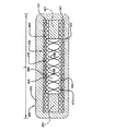
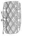
本発明の非空気式タイヤ100の第1の実施形態は、図1に示されている。本発明のタイヤは、地面と係合する径方向外側のトレッド200、剪断バンド320、330及び接続ウェブ500を含んでいる。タイヤトレッド200は、様々な状況でタイヤの性能を高めるために、所望に応じて、リブ、ブロック、出張り、溝及びサイプなどの要素を含んでいてもよい。接続ウェブ500は、以下でより詳細に説明するように、様々な設計を有していてもよい。本発明の非空気式タイヤは、剪断バンド320、330及び接続ウェブ500が効率良く荷重を支えるように、トップローディング構造であるように設計されている。剪断バンド320、330及び接続ウェブは、剪断バンドの剛性がタイヤのばね率に直接関係するように設計されている。接続ウェブは、張力を受けたときタイヤのフットプリント内で座屈又は変形し、圧縮することも圧縮荷重を支えることもない剛性の高い構造であるように設計されている。これは、接続ウェブのうちのフットプリント内にない残りの部分に荷重を支える能力を与え、それにより非常に荷重効率の高い構造をもたらす。剪断バンドが湾曲して道路の障害物を乗り越えられるようにすることが望ましい。近似的な荷重分布は、好ましくは、荷重のおおよそ90%〜100%が剪断バンド及び接続ウェブの上部によって支えられ、したがって接続ウェブの下部が事実上荷重を支えないか好ましくは10%未満の荷重を支えるような荷重分布である。
A first embodiment of a
(剪断バンド)
剪断バンド320、330は、タイヤトレッド200の径方向内方に配置され、かつ、地面と接触するタイヤの底面からスポーク及びハブに荷重を伝達してトップローディング構造を作り出すように機能する、環状構造であることが好ましい。環状構造300は、好ましい変形の形態が剪断過剰曲りであるので、剪断バンドと呼ばれる。
(Shear band)
The
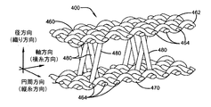
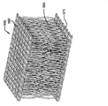
剪断バンド320の第1の実施形態が、図2Aに示されており、かつ、図3Aに示されている開いた3次元スペーサ構造400で構成されている。3次元スペーサ構造400は、ゴム状物質の第1の層331と第2の層341との間に位置決めしてもよい(原寸に比例して示されていない)。ゴム状物質331、341は、所望に応じた厚さとしてもよい。3次元スペーサ構造400は、ファブリックの第1及び第2の層460、470を有するタイプの構造であり、各ファブリックの層は、第1の方向又は緯糸方向(weft direction)に延びている複数の第1の補強部材462と、第2の方向又は経糸方向(warp direction)に延びている複数の第2の補強部材464とで形成されている。第1及び第2の補強部材462、464は、図示のように互いに垂直であってもよく、又は、所望の角度で交差していてもよい。図3Aに示すように、補強部材462は、補強部材464と絡み合わされて又は織り合わされている。第1及び第2の補強部材の層は、編まれていてもよく、織られていてもよく、不織であってもよく、絡み合わされていてもよく又は絡み合わされていなくてもよい。ファブリックの第1及び第2の層462、464は、互いに平行に配向されていることが好ましく、第3の方向又は積重ね方向(pile dimension)に延びている補強接続部材480、490によって互いに相互接続されていることが好ましい。接続する層460、470間の垂直距離、すなわち3次元構造のZ方向寸法は、約2ミリメートルから約25ミリメートルの範囲内、より好ましくは約3ミリメートル〜10ミリメートル、さらに好ましくは5ミリメートル〜10ミリメートルの範囲内である。
A first embodiment of
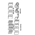
3次元スペーサ構造400は、図3Bに示すような補強接続部材の様々な構成を有してもよい。
The three-
3次元ファブリック構造400は、第1及び第2の層460、470が軸方向に対して平行するように位置合わせされるように、剪断バンド内で配向されることが好ましい。3次元ファブリック構造400は、好ましくは非空気式タイヤ100の径方向に沿った、実質的なZ方向厚さを有している。したがって、開いた3次元ファブリック構造400は、開いたセル495を形成する複数の接続部材480、490を備えている。第1の実施形態における開いたセル495は、空のままである。図2Aに示すように、接続部材480、490の軸方向幅は、剪断バンド320の軸方向幅L未満である。剪断バンドは、接続部材480、490が存在しない、剪断バンドの両側方端部に配置された空洞481をさらに含んでいる。空洞481は、タイヤの剛性を調整するために、ゴム、エラストマー又は他の所望の剛性の材料で充填してもよい。空洞の軸方向幅は、剪断バンドの軸方向幅Lの0%から30%に調節してもよい。
The three-
補強部材又は補強接続部材は、1つ又は複数のヤーン、ワイヤ、1つ又は複数のフィラメント、1つ又は複数の繊維若しくは1つ又は複数の補強コードを含み得る。補強部材又は補強交差部材は、ガラス繊維、炭素繊維、玄武岩繊維、有機繊維、ナイロン、アラミド、ポリエステル、スチールワイヤ又は金属ワイヤ若しくはそれらの組合せで形成されてもよい。補強部材464は、タイヤ赤道面に対して+/−15度以下(−15度以上+15度以下)、より好ましくはタイヤ赤道面に対して+/−10度以下(−10度以上+10度以下)に配向されていてもよい。
The reinforcing member or reinforcing connecting member may comprise one or more yarns, wires, one or more filaments, one or more fibers or one or more reinforcing cords. The reinforcing member or reinforcing cross member may be formed of glass fiber, carbon fiber, basalt fiber, organic fiber, nylon, aramid, polyester, steel wire or metal wire or combinations thereof. The reinforcing
3次元ファブリック構造400は及び/又は補強部材は、良く知られているレソルシノール−ホルムアルデヒド樹脂/ブタジエン−スチレン−ビニルピリジン3量体ラテックス又はレソルシノール−ホルムアルデヒド樹脂/ブタジエン−スチレン−ビニルピリジン3量体ラテックスとブタジエン/スチレンゴムラテックスとの混合物である、RFL接着剤で処理されることが好ましく、そのようなRFL接着剤は、タイヤ産業において、ゴム構成要素へのファブリック、繊維及びテキスタイルコードの接着を促進するために、ファブリック、繊維及びテキスタイルコードの貼付けに使用されている(例えば、米国特許第4,356,219号参照)。補強部材は、シングルエンド浸漬部材(single end dipped member)であってもよい(すなわち、単一の補強部材が、RFL接着剤又は接着促進剤に浸される)。
The three-
3次元ファブリック構造400は、DIN12127による測定で700グラム/平方メートル〜1000グラム/平方メートルの範囲内の密度を有してもよい。3次元ファブリック構造400の圧縮剛性は、DIN/ISO33861による測定で50kPaから600kPaの範囲であってもよく、より好ましくは100kPaから250kPaの範囲であってもよい。
The three-
図3Bに示すような補強接続部材480の軸方向間隔Sもまた、剪断バンドの剛性を制御するために、調節してもよい。間隔Sは、3ミリメートルから8ミリメートルの範囲であってもよい。
The axial spacing S of the reinforcing
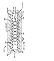
剪断バンドは、3次元スペーサ構造、さらに第1の膜層で構成されている。第1の膜層330は、伸張不可能であることが好ましく、また、3次元構造400の径方向外方に配置されていることが好ましい。剪断バンドは、第1の膜層330に平行に配置された、任意選択の第2の膜層340をさらに備えている。剪断バンドを形成するために2つの膜層が利用される場合、膜層330、340は、層同士の間に3次元スペーサ構造400が配置されるように、3次元スペーサ構造400によって分離されていることが好ましい。ゴム材料の層331、341が、3次元スペーサ構造400を各補強層330、340から分離していることが好ましい。第1の膜層330及び任意選択の第2の膜層340は、それぞれ、タイヤ赤道面に対して0から約+/−10度の範囲内(約−10度から約+10度の範囲内)の角度に配向された補強部材又は補強コードを有している。第1の層の該補強コードの角度は、第2の層の該補強コードの角度の反対向きであることが好ましい。該補強部材又は補強コードは伸張不可能であることがさらに好ましい。
The shear band is composed of a three-dimensional spacer structure and a first film layer. The
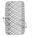
図2Bは、本発明の剪断バンド330の第2の実施形態を示している。第2の実施形態は、以下の違いを除いては図2Aに示す第1の実施形態と同じである。第1及び第2の膜層330、340は、それぞれ、距離SSだけ離間した補強コードを有している。距離SSは、3ミリメートル〜20ミリメートルの間で変わり得る。補強コード331、341は、黄銅で被覆されたスチールワイヤ、例えば2x0.295HT又はWLスチールコードであることが好ましい。剪断バンドは、層460の3次元スペーサ補強部材464と隣接する膜層330の最も近い補強コード331とのまわりに織り合わせられた複数の織り合わせ補強部材493をさらに備えている。したがって、織り合わせ補強部材493は、軸方向に延びて、膜層330と径方向外側の剪断バンドの層460とを相互接続している。同様に、織り合わせ補強部材494は、径方向内側の3次元スペーサ構造の層470と第2の膜層340とを接続している。したがって、3次元スペーサの層470は、別体の伸張不可能な層の必要性を排除している。織り合わせ補強部材493、494は、シングルエンド浸漬部材(single end dipped member)であってもよい(すなわち、単一の補強部材が、RFL接着剤に浸される)。
FIG. 2B shows a second embodiment of the
上記の剪断バンドの実施形態の何れも、図4Aに示す3次元構造を利用してよい。図4に示す3次元構造350は、ファブリックの第1の編物又は織物の360と、ファブリックの第2の編物又は織物の層370とを含んでいる。第1の層及び第2の層は、複数の交差部材380によって継合されている。交差部材380は、90度の角度で、第1及び第2の織物層に接続されている。第1及び第2の織物層360、370は、軸方向に対して平行に配向されていることが好ましい。
Any of the above shear band embodiments may utilize the three-dimensional structure shown in FIG. 4A. The three-
上記の剪断バンド300の実施形態の何れも、交差部材480、490の様々な異なる構成を示す図5〜7に示されている3次元構造を利用してよい。 Any of the embodiments of the shear band 300 described above may utilize the three-dimensional structure shown in FIGS. 5-7 illustrating various different configurations of the cross members 480,490.
上記の剪断バンドの実施形態の何れも、図8に示す3次元構造を利用してよい。3次元構造500は、ファブリックの第1の織物層560と、ファブリックの第2の織物層570とを備えている。第1及び第2の層は、「8」の形状に形成された複数の交差部材580によって継合されている。
Any of the embodiments of the shear band described above may utilize the three-dimensional structure shown in FIG. The three-
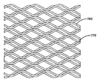
上記の剪断バンドの実施形態の何れも、図9又は10に示す3次元構造を利用してよい。図9の3次元構造700は、ファブリックの第1の編物層760と、ファブリックの第2の編物層770とを備えている。第1及び第2の層は、編まれた複数の間隔空け糸780によって継合されている。第1及び第2の層760、770はそれぞれ、複数の網目によって形成された開口部を有しており、両編物ファブリック層間にはチャネルが形成されており、それらのチャネルはスペーサ糸を含んでいない。
Any of the above shear band embodiments may utilize the three-dimensional structure shown in FIG. The three-
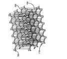
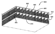
上記の剪断バンドの実施形態の何れも、図11に示す3次元構造を利用してよい。3次元構造800は、2つ以上のデッキ層810、820を備えている。3次元構造800は、ファブリックの第1の織物層860と、ファブリックの第2の織物層870と、中間織物層880とを有している。第1の層860及び中間層880は、複数の交差部材890によって継合されている。第2の層870及び中間層880もまた、複数の交差部材895によって継合されている。交差部材890、895は、図4〜8に示すように斜めになっているか又は湾曲していてもよい。
Any of the above shear band embodiments may utilize the three-dimensional structure shown in FIG. The three-
上記の3次元ファブリック構造の実施形態の何れも、DIN12127による測定で700〜1000グラム/平方メートルの範囲内の密度を有していてもよい。3次元ファブリック構造の圧縮剛性は、DIN/ISO33861による測定で50kPaから600kPaの範囲であってもよく、より好ましくは100kPaから250kPaの範囲であってもよい。 Any of the above three-dimensional fabric structure embodiments may have a density in the range of 700-1000 grams / square meter as measured by DIN12127. The compression stiffness of the three-dimensional fabric structure may be in the range of 50 kPa to 600 kPa, more preferably in the range of 100 kPa to 250 kPa as measured by DIN / ISO 33861.
剪断バンドの中心部の径方向厚さが剪断バンドの両外端部の厚さを超えるように、剪断バンドの両側方端部がテーパ付けされていることが、さらに好ましい。 More preferably, both side ends of the shear band are tapered so that the radial thickness of the center portion of the shear band exceeds the thickness of both outer ends of the shear band.
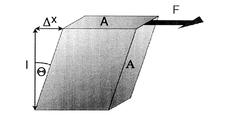
(剪断バンドの特性)
剪断バンドは、全体的な剪断剛性GAを有している。剪断剛性GAは、剪断バンド300から採取した代表試験片のたわみを測定することによって判定してもよい。該試験片の上面は、以下に示すように横力Fにさらされる。該試験片は、剪断バンドから採取した、剪断バンドと同じ径方向厚さを有している代表試料である。次に、剪断剛性GAは、以下の式から算出される。
(Shear band characteristics)
The shear band has an overall shear stiffness GA. The shear rigidity GA may be determined by measuring the deflection of a representative specimen taken from the shear band 300. The top surface of the specimen is exposed to lateral force F as shown below. The test specimen is a representative sample taken from the shear band and having the same radial thickness as the shear band. Next, the shear rigidity GA is calculated from the following equation.
GA=F*L/ΔX、式中、Fは剪断荷重であり、Lは剪断層厚さであり、デルタXは剪断たわみである。 GA = F * L / ΔX, where F is the shear load, L is the shear layer thickness, and Delta X is the shear deflection.
剪断バンドは、全体的な曲げ剛性EIを有している。曲げ剛性EIは、3点曲げ試験を使用して、梁力学(beam mechanics)から判定してもよい。3点曲げ試験は、2つのローラ支持体上に置かれて梁の中央部に加えられた集中荷重にさらされている梁の状況を表す。曲げ剛性EIは、次の式、EI=PL3/48*ΔXから判定され、式中、Pは荷重であり、Lは梁の長さであり、ΔXはたわみである。 The shear band has an overall bending stiffness EI. Bending stiffness EI may be determined from beam mechanics using a three-point bending test. The three point bend test represents the situation of a beam placed on two roller supports and subjected to a concentrated load applied to the center of the beam. The bending stiffness EI is determined from the following equation, EI = PL3 / 48 * ΔX, where P is the load, L is the length of the beam, and ΔX is the deflection.
剪断バンドの曲げ剛性EIを最大限に高めること、及び、剪断剛性GAを最小限に抑えることが望ましい。許容可能なGA/EIの比率は0.01から20の間であり、理想的な範囲は0.01から5の間である。EAは、剪断バンドの伸び剛性(extensible stiffness)であり、張力を加えて長さの変化を測定することにより、実験的に判定される。剪断バンドのEAのEIに対する比率は0.02から100の範囲内であれば許容することができ、理想的な範囲は1から50である。 It is desirable to maximize the bending stiffness EI of the shear band and minimize the shear stiffness GA. An acceptable GA / EI ratio is between 0.01 and 20, with an ideal range between 0.01 and 5. EA is the extensible stiffness of the shear band and is determined experimentally by measuring the change in length by applying tension. The shear band EA to EI ratio is acceptable in the range of 0.02 to 100, with an ideal range of 1 to 50.
剪断バンド300は、15〜30%の範囲内の最大剪断歪みに耐えられることが好ましい。 The shear band 300 is preferably capable of withstanding a maximum shear strain in the range of 15-30%.
剪断バンドは、0.01から20の範囲内のGA/EI、、0.02から100の範囲内のEA/EIの比率、20から2000の範囲内のばね率又はそれらの任意の組合せを有していることが好ましい。剪断バンドは、0.01から5のGA/EIの比率、1から50のEA/EIの比率又は170lB/inのばね率及びそれらの任意の部分的組合せを有していることがより好ましい。タイヤトレッドは、剪断バンドのまわりに巻かれていることが好ましく、また、剪断バンドに一体に成形されていることが好ましい。
接続ウェブ
The shear band has a GA / EI in the range of 0.01 to 20, a ratio of EA / EI in the range of 0.02 to 100, a spring rate in the range of 20 to 2000, or any combination thereof. It is preferable. More preferably, the shear band has a GA / EI ratio of 0.01 to 5 or an EA / EI ratio of 1 to 50 or a spring rate of 170 lb / in and any partial combination thereof. The tire tread is preferably wound around the shear band, and is preferably formed integrally with the shear band.
Connection web
本発明の非空気式タイヤは、図1に示すような接続ウェブ500をさらに含んでいる。接触ウェブは、内半径から外半径まで延びている、円周方向に沿って並べられた複数のスポーク510を備えていることが好ましい。スポークは、径方向に配向されていることが好ましい。スポークは、湾曲していてもよいし真っ直ぐであってもよい。非空気式タイヤは、円周方向に沿って並べられた複数のスポークを2組備えていることが好ましい。スポークは、様々な断面設計を有してもよい。スポークは、剪断層から伝達される荷重を支える働きをする。スポークは、主として引張及び剪断における荷重が加わり、圧縮における荷重は支えない。本明細書で説明するような各スポークは、実質的に非空気式タイヤの軸方向厚さAW未満の軸方向厚さAを有している。軸方向厚さAは、AWの5〜20%の範囲内であり、より好ましくはAWの5〜10%の範囲内である。1つを超えるディスクが利用される場合、各ディスクの軸方向厚さは異なっていてもよいし、同じであってもよい。
The non-pneumatic tire of the present invention further includes a connecting
スポーク510は、径方向に延びていることが好ましい。スポーク510は、径方向に膨らむか又は変形するように設計されている。非空気式タイヤに荷重が加えられる場合、スポークは、接地面を通過するときに実質的に圧縮耐性を持たずに変形して、荷重支持点にゼロの又は取るに足らない圧縮力を与えることになる。スポークの主な荷重は、引張及び剪断を通じたものであり、圧縮を通じたものではない。
The
スポークは、ゴム又は熱可塑性エラストマーなどの弾性材料で形成されていることが好ましい。径方向スポークは、タイヤの径方向変形に対しては低い耐性を有し、タイヤの横方向変形に対しては高い耐性を有するように、設計されている。 The spoke is preferably made of an elastic material such as rubber or thermoplastic elastomer. The radial spokes are designed to have low resistance to radial deformation of the tire and high resistance to lateral deformation of the tire.
選択された材料が熱可塑性エラストマーであった場合、以下の特性を有していることが好ましい。ディスク材料の引張(ヤング)係数は、ISO527−1/−2標準試験法を使用した場合、45MPaから650MPaの範囲内であることが好ましく、85MPaから300MPaであることがより好ましい。ガラス転移温度は、摂氏−25度未満、より好ましくは摂氏−35度未満である。破断時降伏歪みは、30%超、より好ましくは40%超である。破断時伸びは、該降伏歪み以上、より好ましくは200%超である。熱たわみ温度は、0.45MPa下で摂氏40度超、より好ましくは0.45MPa下で摂氏50度超である。ISO179/ISO180試験法を使用した摂氏23度でのアイゾット及びシャルピー切欠き棒試験(Izod and Charpy notched test)で、破断が生じない。該ディスクに適した2種の材料が、ARNITEL PL 420H及びARNITEL PL461の商標名でDSM Productsによって市販されている。 When the selected material is a thermoplastic elastomer, it preferably has the following characteristics: When the ISO 527-1 / -2 standard test method is used, the tensile (Young) coefficient of the disk material is preferably in the range of 45 MPa to 650 MPa, more preferably 85 MPa to 300 MPa. The glass transition temperature is less than -25 degrees Celsius, more preferably less than -35 degrees Celsius. The yield strain at break is greater than 30%, more preferably greater than 40%. The elongation at break is greater than or equal to the yield strain, more preferably greater than 200%. The heat deflection temperature is greater than 40 degrees Celsius under 0.45 MPa, more preferably greater than 50 degrees Celsius under 0.45 MPa. No fracture occurs in the Izod and Charpy notched test at 23 degrees Celsius using the ISO 179 / ISO 180 test method. Two materials suitable for the disk are marketed by DSM Products under the trade names ARNITEL PL 420H and ARNITEL PL461.
上記明細書を読めば他の多くの変形された形態が当業者には明らかであると、本出願人は理解している。そうした変形された形態及び他の変形された形態は、以下の添付された特許請求の範囲によって定義される本発明の技術思想及び範囲に含まれる。 Applicants understand that many other variations will be apparent to those skilled in the art after reading the above specification. Such and other variations are within the spirit and scope of the present invention as defined by the following appended claims.
100 非空気式タイヤ
200 トレッド、タイヤトレッド
300 環状構造、剪断バンド
320 剪断バンド
330 剪断バンド、第1の膜層、補強層
331 ゴム材料の層、補強コード
340 第2の膜層、補強層
341 ゴム材料の層、補強コード
350 3次元構造
360 第1の織物層
370 第2の織物層
380 交差部材
400 開いた3次元スペーサ構造、3次元スペーサ構造、3次元ファブリック構造
460 ファブリックの第1の層、径方向外側の剪断バンドの層
462 第1の補強部材、第1の層
464 第2の補強部材、第2の層、3次元スペーサ補強部材
470 ファブリックの第2の層、径方向内側の3次元スペーサ構造の層
480 補強接続部材、交差部材
481 空洞
490 補強接続部材、交差部材
493 織り合わせ補強部材
494 織り合わせ補強部材
495 開いたセル
500 接続ウェブ、3次元構造
510 スポーク
512 ハブ
560 第1の織物層
570 第2の織物層
580 交差部材
700 3次元構造
760 第1の編物層
770 第2の編物層
780 間隔空け糸
800 3次元構造
810 デッキ層
820 デッキ層
860 第1の織物層
870 第2の織物層
880 中間織物層
890 交差部材
895 交差部材
100
Claims (15)
請求項1〜14の何か1項に記載の剪断バンドと、
を備えた非空気式タイヤ。 An annular tread portion to be grounded;
A shear band according to any one of claims 1-14,
Non-pneumatic tire with
Applications Claiming Priority (2)
| Application Number | Priority Date | Filing Date | Title |
|---|---|---|---|
| US201662321939P | 2016-04-13 | 2016-04-13 | |
| US62/321939 | 2016-04-13 |
Publications (1)
| Publication Number | Publication Date |
|---|---|
| JP2017190130A true JP2017190130A (en) | 2017-10-19 |
Family
ID=58536896
Family Applications (1)
| Application Number | Title | Priority Date | Filing Date |
|---|---|---|---|
| JP2017076191A Pending JP2017190130A (en) | 2016-04-13 | 2017-04-06 | Shear band and non-pneumatic tire |
Country Status (5)
| Country | Link |
|---|---|
| US (1) | US10682887B2 (en) |
| EP (1) | EP3231637A1 (en) |
| JP (1) | JP2017190130A (en) |
| KR (1) | KR20170117335A (en) |
| CN (1) | CN107284142B (en) |
Cited By (1)
| Publication number | Priority date | Publication date | Assignee | Title |
|---|---|---|---|---|
| JP2021030903A (en) * | 2019-08-26 | 2021-03-01 | Toyo Tire株式会社 | Non-pneumatic tires |
Families Citing this family (22)
| Publication number | Priority date | Publication date | Assignee | Title |
|---|---|---|---|---|
| CA2915483C (en) | 2013-06-15 | 2021-11-16 | Ronald Thompson | Annular ring and non-pneumatic tire |
| CA2976055A1 (en) | 2015-02-04 | 2016-08-11 | Advancing Mobility, Llc. | Non-pneumatic tire and other annular devices |
| WO2017106750A1 (en) | 2015-12-16 | 2017-06-22 | Thompson Ronald H | Track system for traction of a vehicle |
| US10639934B2 (en) * | 2016-11-22 | 2020-05-05 | The Goodyear Tire & Rubber Company | Shear band for a structurally supported tire |
| FR3061675A1 (en) * | 2017-01-12 | 2018-07-13 | Compagnie Generale Des Etablissements Michelin | ASSEMBLY COMPRISING A ROMPABLE STRUCTURE AND A CARRIER STRUCTURE |
| FR3061674A1 (en) * | 2017-01-12 | 2018-07-13 | Compagnie Generale Des Etablissements Michelin | ASSEMBLY COMPRISING PARTIALLY BREAKABLE FABRIC AND CARRIER STRUCTURE |
| US11179969B2 (en) | 2017-06-15 | 2021-11-23 | Camso Inc. | Wheel comprising a non-pneumatic tire |
| EP3833551B1 (en) * | 2018-08-06 | 2024-07-24 | Compagnie Generale Des Etablissements Michelin | Resilient composite structural support |
| WO2020094979A1 (en) * | 2018-11-09 | 2020-05-14 | Compagnie Generale Des Etablissements Michelin | Device of pneumatic tyre type with flexible filamentary elements, for a vehicle |
| FR3090497B3 (en) | 2018-12-24 | 2020-12-04 | Michelin & Cie | Assembly for a tire, tire and associated manufacturing processes |
| FR3090498A3 (en) * | 2018-12-24 | 2020-06-26 | Michelin & Cie | Assembly for a tire, tire and associated manufacturing methods |
| KR102187804B1 (en) * | 2019-04-15 | 2020-12-09 | 한국타이어앤테크놀로지 주식회사 | Non-pneumatic tire having block type reinforcement |
| US12377684B2 (en) * | 2019-11-13 | 2025-08-05 | Bridgestone Americas Tire Operations, Llc | Non-pneumatic tire having multilayer spokes |
| JP7418197B2 (en) * | 2019-12-13 | 2024-01-19 | Toyo Tire株式会社 | non-pneumatic tires |
| US20210300120A1 (en) * | 2020-03-30 | 2021-09-30 | The Goodyear Tire & Rubber Company | Shear band |
| KR102335895B1 (en) * | 2020-05-13 | 2021-12-07 | 넥센타이어 주식회사 | Non-pneumatic tire |
| CN111942081B (en) * | 2020-09-18 | 2026-01-27 | 广西玉林金特安科技有限公司 | Non-pneumatic tire |
| JP2024501485A (en) * | 2020-12-18 | 2024-01-12 | ブリヂストン アメリカズ タイヤ オペレーションズ、 エルエルシー | Non-pneumatic tire with fiber metal laminate structure |
| WO2022139800A1 (en) * | 2020-12-22 | 2022-06-30 | Compagnie Generale Des Etablissements Michelin | Spoke for non-pneumatic tire having extended nose reinforcement |
| WO2022235697A1 (en) * | 2021-05-03 | 2022-11-10 | The Carlstar Group Llc | Non-pneumatic tire with multi angle tension control reinforcements |
| US20230191840A1 (en) * | 2021-12-17 | 2023-06-22 | The Goodyear Tire & Rubber Company | Non-pneumatic tire with improved shear band |
| US20230191835A1 (en) * | 2021-12-17 | 2023-06-22 | The Goodyear Tire & Rubber Company | Non-pneumatic tire with improved shear band |
Family Cites Families (10)
| Publication number | Priority date | Publication date | Assignee | Title |
|---|---|---|---|---|
| US2657716A (en) | 1950-10-28 | 1953-11-03 | Wingfoot Corp | Inflatable fabric segment of curved configuration |
| US4356219A (en) | 1980-12-03 | 1982-10-26 | The Goodyear Tire & Rubber Company | Treated yarn, method of preparation and rubber/cord composite |
| DE19944437B4 (en) | 1999-09-16 | 2008-05-29 | Volkswagen Ag | Energy absorbing element |
| WO2009055919A1 (en) | 2007-10-30 | 2009-05-07 | Zvonimir Segaric | Composite material |
| US7910193B2 (en) | 2008-11-10 | 2011-03-22 | Mkp Structural Design Associates, Inc. | Three-dimensional auxetic structures and applications thereof |
| US8544515B2 (en) * | 2008-11-10 | 2013-10-01 | Mkp Structural Design Associates, Inc. | Ultralightweight runflat tires based upon negative poisson ratio (NPR) auxetic structures |
| WO2011112920A1 (en) * | 2010-03-12 | 2011-09-15 | Michelin Recherche Et Technique, S.A. | Structually supported, non-pneumatic wheel with continuous loop reinforcement assembly |
| US8688421B2 (en) | 2010-03-31 | 2014-04-01 | Compagnie Generale Des Etablissements Michelin | Method to design honeycombs for a shear flexible structure |
| WO2012098130A1 (en) | 2011-01-17 | 2012-07-26 | Vds Weaving Nv | A tridimensional woven fabric, an integrated permeate channel membrane comprising said fabric and uses thereof |
| CN202787813U (en) | 2012-08-28 | 2013-03-13 | 吴伯明 | Three-dimensional reinforced heat insulation and decoration integral composite plate |
-
2017
- 2017-04-06 JP JP2017076191A patent/JP2017190130A/en active Pending
- 2017-04-06 US US15/480,432 patent/US10682887B2/en active Active
- 2017-04-11 EP EP17166046.7A patent/EP3231637A1/en not_active Withdrawn
- 2017-04-12 KR KR1020170047257A patent/KR20170117335A/en not_active Withdrawn
- 2017-04-13 CN CN201710241016.5A patent/CN107284142B/en active Active
Cited By (2)
| Publication number | Priority date | Publication date | Assignee | Title |
|---|---|---|---|---|
| JP2021030903A (en) * | 2019-08-26 | 2021-03-01 | Toyo Tire株式会社 | Non-pneumatic tires |
| JP7324088B2 (en) | 2019-08-26 | 2023-08-09 | Toyo Tire株式会社 | non-pneumatic tires |
Also Published As
| Publication number | Publication date |
|---|---|
| US20170297373A1 (en) | 2017-10-19 |
| EP3231637A1 (en) | 2017-10-18 |
| CN107284142B (en) | 2020-02-07 |
| CN107284142A (en) | 2017-10-24 |
| KR20170117335A (en) | 2017-10-23 |
| US10682887B2 (en) | 2020-06-16 |
Similar Documents
| Publication | Publication Date | Title |
|---|---|---|
| JP2017190130A (en) | Shear band and non-pneumatic tire | |
| JP2017190127A (en) | Shear band and non-pneumatic tire | |
| JP2017190128A (en) | Shear band and non-pneumatic tire | |
| JP2017190129A (en) | Non-pneumatic tire | |
| US8931531B2 (en) | System for non-pneumatic support of a vehicle | |
| JP6929054B2 (en) | Non-pneumatic tires including geodesic ply and beads | |
| US8720504B2 (en) | System for non-pneumatic support of a vehicle | |
| US9616713B2 (en) | Non-pneumatic tire | |
| BR102017025049A2 (en) | SHIFTING RANGE FOR A STRUCTURALLY SUPPORTED TIRE | |
| BRPI0621824B1 (en) | SHEAR BAND, AND, TIRE | |
| BR102016028734A2 (en) | TIRE WITH STRUCTURAL SUPPORT | |
| JP2023036026A (en) | Non-pneumatic tire with improved shear band | |
| EP4197810A1 (en) | Non-pneumatic tire with improved shear band | |
| KR20230033626A (en) | Non-pneumatic tire with improved shear band | |
| US20230191840A1 (en) | Non-pneumatic tire with improved shear band |