JP2017189484A - Washing and drying machine - Google Patents

Washing and drying machine Download PDF

Info

Publication number
JP2017189484A
JP2017189484A JP2016081725A JP2016081725A JP2017189484A JP 2017189484 A JP2017189484 A JP 2017189484A JP 2016081725 A JP2016081725 A JP 2016081725A JP 2016081725 A JP2016081725 A JP 2016081725A JP 2017189484 A JP2017189484 A JP 2017189484A
Authority
JP
Japan
Prior art keywords
washing
air
drying
tub
laundry
Prior art date
Legal status (The legal status is an assumption and is not a legal conclusion. Google has not performed a legal analysis and makes no representation as to the accuracy of the status listed.)
Pending
Application number
JP2016081725A
Other languages
Japanese (ja)
Inventor
昌 坂東
Akira Bando
昌 坂東
義徳 宗野
Yoshinori Muneno
義徳 宗野
祐太朗 林
Yutaro Hayashi
祐太朗 林
Current Assignee (The listed assignees may be inaccurate. Google has not performed a legal analysis and makes no representation or warranty as to the accuracy of the list.)
Hitachi Appliances Inc
Original Assignee
Hitachi Appliances Inc
Priority date (The priority date is an assumption and is not a legal conclusion. Google has not performed a legal analysis and makes no representation as to the accuracy of the date listed.)
Filing date
Publication date
Application filed by Hitachi Appliances Inc filed Critical Hitachi Appliances Inc
Priority to JP2016081725A priority Critical patent/JP2017189484A/en
Priority to CN201710214193.4A priority patent/CN107299493B/en
Priority to TW106112257A priority patent/TWI649474B/en
Publication of JP2017189484A publication Critical patent/JP2017189484A/en
Pending legal-status Critical Current

Links

Images

Classifications

    • DTEXTILES; PAPER
    • D06TREATMENT OF TEXTILES OR THE LIKE; LAUNDERING; FLEXIBLE MATERIALS NOT OTHERWISE PROVIDED FOR
    • D06FLAUNDERING, DRYING, IRONING, PRESSING OR FOLDING TEXTILE ARTICLES
    • D06F39/00Details of washing machines not specific to a single type of machines covered by groups D06F9/00 - D06F27/00 
    • D06F39/04Heating arrangements
    • DTEXTILES; PAPER
    • D06TREATMENT OF TEXTILES OR THE LIKE; LAUNDERING; FLEXIBLE MATERIALS NOT OTHERWISE PROVIDED FOR
    • D06FLAUNDERING, DRYING, IRONING, PRESSING OR FOLDING TEXTILE ARTICLES
    • D06F39/00Details of washing machines not specific to a single type of machines covered by groups D06F9/00 - D06F27/00 
    • D06F39/02Devices for adding soap or other washing agents
    • D06F39/022Devices for adding soap or other washing agents in a liquid state

Abstract

PROBLEM TO BE SOLVED: To provide a washing and drying machine which secures an air blowing path even without including a circulation pump, and which has improved washing performance by warming laundry in which a detergent solution is impregnated with warm air.SOLUTION: A washing machine includes: a washing tub; a drying unit 60 which has an inlet and an outlet 22, and for drying the air in the washing tub taken in from the inlet and exhausting it from the outlet 22; a blowout port connected to the outlet 22 and for blowing out the air dried by the drying unit 60 from the upper part of the washing tub; and a suction port 145 connected to the inlet, and for sucking the air in the washing tub guided to the drying unit 60 from a non-submersion position of the washing tub. The non-submersion position is a position above a liquid level of a detergent liquid before starting washing, and the air in the washing tub sucked from the suction port 145 is dried in the drying unit 60, blown out from the blowout port and circulated.SELECTED DRAWING: Figure 4

Description

本発明は、洗濯乾燥機に関する。   The present invention relates to a washing / drying machine.

本技術分野の背景技術として、下記特許文献1の要約書には、「本発明に関わる洗濯乾燥機は、防振支持され洗濯水、すすぎ水を溜める外槽と、洗濯物が投入され外槽内に回転自在に支持され回転駆動される内槽と、内槽の内底面部に配置され回転駆動される回転翼と、内槽内の脱水後の水分を含んだ洗濯物に温風を吹き込み乾燥させる乾燥機能とを備える洗濯乾燥機であって、回転翼上に、それぞれ独立した形状の多数の凸部が点在して形成されている。」と記載されている。   As a background art of this technical field, the abstract of the following Patent Document 1 states that “a washing / drying machine according to the present invention is supported by vibration isolation and has an outer tub for storing washing water and rinsing water; Warm air is blown into the inner tub that is rotatably supported and rotated inside, the rotor blade that is arranged on the inner bottom surface of the inner tub and is driven to rotate, and the dehydrated laundry in the inner tub. It is a washing and drying machine having a drying function for drying, and is formed with a large number of independent convex portions dotted on the rotary blades. "

特許文献1に記載の洗濯乾燥機は、洗濯工程時に洗濯水を内槽から排出して再び給水して循環する構成を備え、回転翼が沈む程度の洗濯水を付与して洗濯を行う。   The washing / drying machine described in Patent Document 1 has a configuration in which washing water is discharged from the inner tub and supplied and circulated again during the washing process, and washing is performed by applying washing water that sinks the rotor blades.

特開2010‐233756号公報JP 2010-233756 A

洗濯性能を更に向上させるため、洗剤の化学的な洗浄力を有効に活用する高濃度の洗剤液を洗濯物にむらなく散布、浸透させ、温風を送風して加温する方法の適用が考えられる。
特許文献1に記載の洗濯乾燥機は、本体下部に循環ポンプを搭載するため、循環ポンプで洗浄液を循環させることにより送風経路を確保することが可能である。
In order to further improve the washing performance, it is considered to apply a method in which a high concentration detergent solution that effectively utilizes the chemical cleaning power of the detergent is evenly spread and infiltrated into the laundry and warmed by blowing hot air. It is done.
Since the washing / drying machine described in Patent Document 1 is equipped with a circulation pump at the lower part of the main body, it is possible to secure a ventilation path by circulating the cleaning liquid with the circulation pump.

しかし、循環ポンプを搭載しない洗濯乾燥機においては、洗濯槽内に水を溜めて脈動翼盤(パルセータ)を回転させて洗剤液を洗濯物に浸透させている。このため、乾燥時に使用する送風経路は本体下部の部分が水没して、乾燥時に使用する送風経路を使用して温風を循環させることができず、洗濯物を温めることはできない。   However, in a washing / drying machine not equipped with a circulation pump, water is accumulated in a washing tub and a pulsating blade (pulsator) is rotated to allow the detergent liquid to penetrate into the laundry. For this reason, as for the ventilation path used at the time of drying, the lower part of the main body is submerged, the hot air cannot be circulated using the ventilation path used at the time of drying, and the laundry cannot be heated.

本願発明は、当該事情に鑑みてなされたものであり、循環ポンプを備えなくとも送風経路を確保し、洗剤液を浸透させた洗濯物を温風で温めることにより洗濯性能を向上させた洗濯乾燥機を提供することを課題とする。   The present invention has been made in view of the above circumstances, and it is possible to secure a ventilation path without a circulation pump, and to improve the washing performance by warming the laundry infiltrated with the detergent liquid with warm air. It is an object to provide a machine.

本発明は、洗濯物を収容する洗濯槽と、入口と出口を有し、前記入口から取り込んだ前記洗濯槽内の空気を乾燥させて前記出口から排出する乾燥ユニットと、前記乾燥ユニットの出口と接続され、前記乾燥ユニットによって乾燥された空気を前記洗濯槽の上方から吹き出す吹出し口と、前記乾燥ユニットの入口と接続され、前記乾燥ユニットに導く前記洗濯槽内の空気を前記洗濯槽の非水没位置から吸い込む吸込み口と、を備え、前記非水没位置は、洗濯開始前の洗剤液の液面よりも上の位置であり、前記吸込み口から吸い込んだ前記洗濯槽内の空気を前記乾燥ユニットで乾燥させて前記吹出し口から吹き出して循環させることを特徴とする洗濯乾燥機。   The present invention includes a washing tub for storing laundry, an inlet and an outlet, a drying unit that dries air in the washing tub taken from the inlet and discharges the air from the outlet, and an outlet of the drying unit. Connected to the outlet for blowing air dried by the drying unit from above the washing tub, and to the inlet of the drying unit, the air in the washing tub leading to the drying unit is not submerged in the washing tub And the non-submerged position is a position above the level of the detergent liquid before the start of washing, and the drying unit sucks air in the washing tub sucked from the suction opening. A washing and drying machine, wherein the washing and drying machine is dried and blown out from the outlet.

本発明によれば、循環ポンプを備えなくとも送風経路を確保し、洗剤液を浸透させた洗濯物を温風で温めることにより洗濯性能を向上させた洗濯乾燥機を提供することができる。   ADVANTAGE OF THE INVENTION According to this invention, even if it does not provide a circulation pump, the washing-drying machine which secured the ventilation path | route and improved washing performance by warming the laundry which permeated the detergent liquid with warm air can be provided.

本実施形態に係る洗濯乾燥機を示す外観斜視図である。It is an external appearance perspective view which shows the washing-drying machine which concerns on this embodiment. 本実施形態に係る洗濯乾燥機の概略構造を示す斜視図である。It is a perspective view which shows schematic structure of the washing / drying machine which concerns on this embodiment. 本実施形態に係る洗濯乾燥機の概略構造を示す縦断面図である。It is a longitudinal cross-sectional view which shows schematic structure of the washing / drying machine which concerns on this embodiment. 本実施形態に係る洗濯乾燥機の送風経路の概略配置を示す斜視図である。It is a perspective view which shows schematic arrangement | positioning of the ventilation path | route of the washing / drying machine which concerns on this embodiment. 本実施形態に係る洗濯乾燥機の送風経路の概略配置を示す正面図である。It is a front view which shows schematic arrangement | positioning of the ventilation path | route of the washing-drying machine which concerns on this embodiment. 本実施形態に係る洗濯乾燥機の左側断面図である。It is a left sectional view of the washing and drying machine concerning this embodiment. 本実施形態に係る洗濯乾燥機の概略平面図である。It is a schematic plan view of the washing / drying machine concerning this embodiment. 本実施形態に係る洗濯乾燥機の一部を切り欠いた斜視図である。It is the perspective view which notched a part of washing-drying machine concerning this embodiment. 本実施形態に係る洗濯乾燥機の外槽カバーの分解斜視図である。It is a disassembled perspective view of the outer tub cover of the washing / drying machine concerning this embodiment. 本実施形態に係る洗濯乾燥機の外槽カバーの断面図である。It is sectional drawing of the outer tank cover of the washing / drying machine which concerns on this embodiment. 本実施形態に係る洗濯乾燥機の乾燥ユニット上部ダクトの分解斜視図である。It is a disassembled perspective view of the drying unit upper part duct of the washing / drying machine concerning this embodiment. 本実施形態に係る洗濯乾燥機の電気的構成を示すブロック図である。It is a block diagram which shows the electric constitution of the washing / drying machine which concerns on this embodiment. 本実施形態に係る洗濯乾燥機の制御を示すフローチャートである。It is a flowchart which shows control of the washing-drying machine which concerns on this embodiment. 第2実施形態に係る洗濯乾燥機の概略構造を示す模式図である。It is a schematic diagram which shows schematic structure of the washing / drying machine which concerns on 2nd Embodiment. 第3実施形態に係る洗濯乾燥機の概略構造を示す模式図である。It is a schematic diagram which shows schematic structure of the washing / drying machine which concerns on 3rd Embodiment.

<第1実施形態>
[実施形態の全体構成]
本発明の実施形態について、適宜、図面を参照しながら詳細に説明する。本実施形態は以下の内容に限定されるものではなく、本発明の趣旨の範囲内において適宜変更して実施可能である。
なお、各図において、共通する部分には同一の符号を付し重複した説明を省略する。
<First Embodiment>
[Overall Configuration of Embodiment]
Embodiments of the present invention will be described in detail with reference to the drawings as appropriate. The present embodiment is not limited to the following contents, and can be implemented with appropriate modifications within the scope of the gist of the present invention.
In each figure, common portions are denoted by the same reference numerals, and redundant description is omitted.

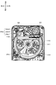
図1は、本実施形態に係る洗濯乾燥機100を示す外観斜視図である。図1は、外蓋3を開けた状態を示している。
図1等に示す様に、外蓋3が開閉する方向を前方後方、洗濯乾燥機100に向かって右を右方、左を左方、鉛直上向きを上方とする。すなわち、図1等に示す様に前後、上下、左右を定義する。
FIG. 1 is an external perspective view showing a washing / drying machine 100 according to the present embodiment. FIG. 1 shows a state in which the outer lid 3 is opened.
As shown in FIG. 1 and the like, the direction in which the outer lid 3 opens and closes is the front rear, the right toward the washing and drying machine 100 is the right, the left is the left, and the vertically upward direction is the upper. That is, as shown in FIG.

図1に示すように、洗濯乾燥機100は、外郭が鋼板と樹脂成型品とを組み合わせて構成された筐体1を備えている。筐体1の上部には、樹脂製のトップカバー2が設けられている。トップカバー2には、洗濯乾燥機100の上部を開閉する外蓋3が設けられている。   As shown in FIG. 1, the washing / drying machine 100 includes a housing 1 whose outer shell is configured by combining a steel plate and a resin molded product. A resin top cover 2 is provided on the top of the housing 1. The top cover 2 is provided with an outer lid 3 that opens and closes the upper part of the washing / drying machine 100.

筺体1は、外郭が鋼板と樹脂成型品とを組み合わせて構成されたものであり、全体を支持するベースと、前板と、後板と、左右の側板と、を備えて略四角箱状に構成されている。筐体1の内部の中央部には、有底円筒状に形成された内槽9(図3参照)および外槽10(図2参照)が設けられている。   The casing 1 is configured by combining a steel plate and a resin molded product with an outer shell, and includes a base that supports the whole, a front plate, a rear plate, and left and right side plates in a substantially square box shape. It is configured. An inner tub 9 (see FIG. 3) and an outer tub 10 (see FIG. 2) formed in a cylindrical shape with a bottom are provided at the center inside the housing 1.

外蓋3は、後ろ側に開くことにより筐体1の上部に形成された開口部1aを開放するように構成されている。   The outer lid 3 is configured to open an opening 1 a formed in the upper portion of the housing 1 by opening it to the rear side.

トップカバー2には、内槽9内に洗濯物を投入するための開口1aが形成されている。この開口1aは、上面視(平面視)において略半円状に形成され、直線部分が奥側に位置し、曲線部分が手前側に位置するように構成されている。また、開口1aは、径方向外側に延びる上端面2bと、鉛直方向下方に延びる周面とを有している。   The top cover 2 is formed with an opening 1 a for putting laundry into the inner tub 9. The opening 1a is formed in a substantially semicircular shape in a top view (plan view), and is configured such that a straight line portion is located on the back side and a curved line portion is located on the near side. The opening 1a has an upper end surface 2b extending radially outward and a peripheral surface extending downward in the vertical direction.

トップカバー2の前面には、洗濯乾燥機100の電源のオン/オフを行う電源スイッチ5、運転コースの設定等に使用する各種の操作ボタンスイッチ、運転状態の表示等を行う表示器を備えた操作パネル8(図2参照)が設けられている。操作パネル8は、開口1aの手前側において横長四角状に形成されている。操作パネル8は、機体底部に設けられたマイクロコンピュータ(不図示)と電気的に接続されている。   On the front surface of the top cover 2, a power switch 5 for turning on / off the power of the washing / drying machine 100, various operation button switches used for setting a driving course, and a display for displaying a driving state are provided. An operation panel 8 (see FIG. 2) is provided. The operation panel 8 is formed in a horizontally long rectangular shape on the front side of the opening 1a. The operation panel 8 is electrically connected to a microcomputer (not shown) provided on the bottom of the machine body.

トップカバー2の前面には、洗剤(固形、液体)や仕上げ剤などを投入するための洗剤・仕上げ剤容器28が、操作パネル8の左側に隣接して設けられている。   On the front surface of the top cover 2, a detergent / finishing agent container 28 for introducing a detergent (solid, liquid) or a finishing agent is provided adjacent to the left side of the operation panel 8.

洗剤・仕上げ剤容器28は、上面視(平面視)において略三角形状に形成され(図2参照)、蓋体2aにより上部を覆われる。蓋体2aは、操作パネル8の表面に隣接する平面視四角形状の表面2a1(第2の面)と、表面2a1の後方に位置する平面視略三角形状の表面2a2と、を有している。又、表面2a2の高さは、表面2a1よりも低く形成されている。表面2a2は、上端面2bと面一になるように構成されている。   The detergent / finishing agent container 28 is formed in a substantially triangular shape when viewed from above (plan view) (see FIG. 2), and the upper part is covered with the lid 2a. The lid 2a has a planar surface 2a1 (second surface) adjacent to the surface of the operation panel 8 and a substantially triangular surface 2a2 in plan view located behind the surface 2a1. . Moreover, the height of the surface 2a2 is formed lower than the surface 2a1. The surface 2a2 is configured to be flush with the upper end surface 2b.

操作パネル8の表面と蓋体2aの一部である表面2a1とは、面一となり、全体として左右方向に細長い四角形状の平坦な面となるように構成されている。また、蓋体2aの表面2a2は、開口1aの上端面2bおよび周面と面一となるように構成されている。   The surface of the operation panel 8 and the surface 2a1, which is a part of the lid 2a, are flush with each other, and are configured to be a flat rectangular surface that is elongated in the left-right direction as a whole. Further, the surface 2a2 of the lid 2a is configured to be flush with the upper end surface 2b and the peripheral surface of the opening 1a.

操作パネル8の表面(第2の面)および洗剤・仕上げ剤容器28の蓋体2aの表面2a1(第2の面)は、縁部(第1の面)よりも低い位置(鉛直方向の下方となる位置)に形成されている。すなわち、第2の面の高さは、トップカバー2の開口1aの上端縁部と略同じ高さ、換言すると第1の面からユーザの手の厚み分低い位置に設定される。   The surface (second surface) of the operation panel 8 and the surface 2a1 (second surface) of the lid 2a of the detergent / finishing agent container 28 are positioned lower than the edge (first surface) (downward in the vertical direction). Is formed). That is, the height of the second surface is set to substantially the same height as the upper end edge of the opening 1a of the top cover 2, in other words, a position lower by the thickness of the user's hand from the first surface.

洗濯乾燥機100には、運転中に外蓋3を解放できないようにするためのロック機構が設けられている。このロック機構は、外蓋3の裏面側に設けられたロック突起と、トップカバー2の上端面に設けられたロック孔とによって構成されている。ロック突起には、左右方向に貫通する孔が形成されており、外蓋3を閉じて、ロック突起がロック孔に挿入されたときに、ロック孔の内部に設けられたロックピン(不図示)が孔に挿入されることで外蓋3が開かないようにロックされる。   The washing / drying machine 100 is provided with a lock mechanism for preventing the outer lid 3 from being released during operation. This lock mechanism is configured by a lock protrusion provided on the back side of the outer lid 3 and a lock hole provided on the upper end surface of the top cover 2. The lock protrusion has a hole penetrating in the left-right direction. When the outer lid 3 is closed and the lock protrusion is inserted into the lock hole, a lock pin (not shown) provided inside the lock hole is formed. Is inserted into the hole and locked so that the outer lid 3 does not open.

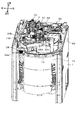
図2は、本実施形態に係る洗濯乾燥機100の概略構造を示す、トップカバー2、外蓋3、及び、筺体1の一部を省略した斜視図である。
筐体1の内部の中央部には、有底円筒状に形成された外槽10および内槽9(図3参照)が設けられている。
FIG. 2 is a perspective view showing a schematic structure of the washing / drying machine 100 according to the present embodiment, with the top cover 2, the outer lid 3, and a part of the casing 1 omitted.
An outer tub 10 and an inner tub 9 (see FIG. 3) formed in a bottomed cylindrical shape are provided in the central portion inside the housing 1.

洗濯乾燥機100の後部には、給水電磁弁4が設けられており、給水電磁弁4の上部には、水道水(清水)を供給するための接続口4aが形成されている。接続口4aの内部には給水フィルタ(不図示)が設けられており、水道水に含まれるゴミがここで除去される。   A water supply electromagnetic valve 4 is provided at the rear part of the washing / drying machine 100, and a connection port 4 a for supplying tap water (fresh water) is formed above the water supply electromagnetic valve 4. A water supply filter (not shown) is provided inside the connection port 4a, and dust contained in the tap water is removed here.

外槽10は、有底円筒状に形成され、内槽9を同軸上に内包している(図3参照)。外槽10は、洗濯水を貯水する。又、外槽10は、筐体1の上端部の四隅部に設けた隅板(不図示)に係止して垂下させた4本の支持棒に緩衝装置(不図示)を介して該筐体1内の中心部に弾性支持されている。   The outer tub 10 is formed in a bottomed cylindrical shape and encloses the inner tub 9 coaxially (see FIG. 3). The outer tub 10 stores washing water. The outer tub 10 has four support rods that are suspended and suspended from corner plates (not shown) provided at the four corners of the upper end of the casing 1 via a shock absorber (not shown). Elastically supported at the center of the body 1.

外槽10の上縁部には、内槽9の上方を閉塞するとともに外槽10の上部開口を閉塞する外槽カバー14(図4参照)が設けられている。外槽カバー14は、洗濯物投入口141と、この洗濯物投入口141(図7参照)を開閉する内蓋23とを備えている。内蓋23は、洗濯物投入口141の後端に設けられたヒンジ機構23aを介して洗濯物投入口141の全体を開閉するように構成されている(図2参照)。   An outer tub cover 14 (see FIG. 4) is provided at the upper edge of the outer tub 10 to close the upper portion of the inner tub 9 and close the upper opening of the outer tub 10. The outer tub cover 14 includes a laundry input port 141 and an inner lid 23 that opens and closes the laundry input port 141 (see FIG. 7). The inner lid 23 is configured to open and close the entire laundry input port 141 via a hinge mechanism 23a provided at the rear end of the laundry input port 141 (see FIG. 2).

駆動装置13は、図2に示す様に、インバータ駆動電動機又は可逆回転型のコンデンサ分相単相誘導電動機を使用した電動機とクラッチと遊星歯車減速機構(不図示)を内蔵して構成されている。又、駆動装置13は、マイコン(不図示)によって電動機とクラッチを制御することによって、クラッチが内槽9を静止させるように係止、又は自由に回転できるように解放した状態で、脈動翼盤11(パルセータともいう)を繰り返し正逆回転させる洗濯駆動モードと、内槽9と脈動翼盤11とを一体的に同一方向に回転させる脱水駆動モードと、を選択的に実行する機能を有する。   As shown in FIG. 2, the drive device 13 is configured to include an inverter drive motor or a motor using a reversible rotation type capacitor phase-separated single-phase induction motor, a clutch, and a planetary gear reduction mechanism (not shown). . Further, the driving device 13 controls the electric motor and the clutch by a microcomputer (not shown), and the pulsation blade is in a state in which the clutch is locked so as to make the inner tank 9 stationary or can be freely rotated. 11 (also referred to as a pulsator) repeatedly has a function of selectively executing a washing drive mode in which the forward and reverse rotation is repeated and a dehydration drive mode in which the inner tub 9 and the pulsating blade 11 are integrally rotated in the same direction.

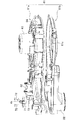
図3は、本実施形態に係る洗濯乾燥機の概略構造を示す縦断面図である。
内槽9は、洗濯兼脱水槽として機能するものであり、有底円筒状に形成され、鉛直方向(上下方向)に回転軸を有している。また、内槽9は、その外周壁に通水および通風のための複数の小さな貫通孔9aが形成されるとともに、その底壁に通水および通風のための複数の貫通孔が形成されている(不図示)。又、内槽9は、駆動装置13によって回転可能に支持されている。
FIG. 3 is a longitudinal sectional view showing a schematic structure of the washing / drying machine according to the present embodiment.
The inner tub 9 functions as a washing / dehydrating tub, is formed in a bottomed cylindrical shape, and has a rotation axis in the vertical direction (vertical direction). The inner tub 9 has a plurality of small through holes 9a for water passage and ventilation on the outer peripheral wall thereof, and a plurality of through holes for water passage and ventilation on the bottom wall thereof. (Not shown). Further, the inner tank 9 is rotatably supported by the driving device 13.

脈動翼盤11は、略円盤状に形成され、内槽9の底部に設けられている。又、脈動翼盤11は、駆動装置13によって回転可能に支持されている。これにより、洗い時やすすぎ時に、脈動翼盤11を回転させることで洗濯水を洗濯物ごと攪拌することができる。   The pulsating blade 11 is formed in a substantially disk shape and is provided at the bottom of the inner tank 9. Further, the pulsating blade 11 is supported rotatably by a driving device 13. Thus, the washing water can be stirred together with the laundry by rotating the pulsating blade 11 when washing or rinsing.

外槽10は筐体1に対して弾性支持されているので、脈動翼盤11が回転駆動されると、内槽9が外槽10とともに揺動する。外槽10が揺動すると、これに伴って外槽カバー14も揺動する。   Since the outer tub 10 is elastically supported with respect to the housing 1, the inner tub 9 swings together with the outer tub 10 when the pulsating blade 11 is rotationally driven. When the outer tub 10 swings, the outer tub cover 14 swings accordingly.

流体バランサ12は、合成樹脂等でリング状に形成され、内槽9の内壁の上端縁部(上縁部)に固定されている。この流体バランサ12は、内部に比重の大きな流体(塩水等)を封入して構成され、内槽9の回転時に洗濯物の偏り等によって偏心が生じたときに、流体バランサ12内での流体の移動によって偏心を打ち消し、回転のバランスを維持する機能を有している。   The fluid balancer 12 is formed in a ring shape with synthetic resin or the like, and is fixed to the upper end edge (upper edge) of the inner wall of the inner tank 9. The fluid balancer 12 is configured by enclosing a fluid having a large specific gravity (salt water or the like) in the interior thereof, and when the inner tub 9 rotates, the eccentricity of the laundry due to the unevenness of the laundry, etc. It has the function of canceling eccentricity by movement and maintaining the balance of rotation.

外槽10の底部には、通水通気口(不図示)が設けられている。通水通気口には、外槽10と、排水弁15(図2参照)とを接続する継手16(図4参照)が設けられている。   A water vent (not shown) is provided at the bottom of the outer tub 10. A joint 16 (see FIG. 4) for connecting the outer tub 10 and the drain valve 15 (see FIG. 2) is provided in the water vent.

内槽9内には、蛇腹管29cを介して、水道水が導入される。洗濯水は、必要に応じて、排水弁15、排水ホース(不図示)を介して排水される。   Tap water is introduced into the inner tank 9 through the bellows tube 29c. Washing water is drained through a drain valve 15 and a drain hose (not shown) as necessary.

内槽9は、上向きに凹形状の底板9eを有している。底板9eの底面には、外槽10と連通する貫通孔(不図示)が複数個所に形成されている。   The inner tank 9 has a bottom plate 9e that is concave upward. On the bottom surface of the bottom plate 9e, through holes (not shown) communicating with the outer tub 10 are formed at a plurality of locations.

内槽9の内周面には、循環流路部材9fが取り付けられている。循環流路部材9fは、例えば、合成樹脂等で一体に形成され、裏面側に導水路を有しており、導水路と内槽9の内周面との間で循環水路9cを構成している。循環流路部材9fの上部には、流路の出口としての洗濯水を内槽9内に散水する吐出口9dが形成されている。   A circulation channel member 9 f is attached to the inner peripheral surface of the inner tank 9. The circulation channel member 9f is formed integrally with, for example, a synthetic resin and has a water conduit on the back surface side, and the circulation channel 9c is configured between the water conduit and the inner peripheral surface of the inner tank 9. Yes. At the upper part of the circulation channel member 9f, a discharge port 9d for spraying washing water as an outlet of the channel into the inner tub 9 is formed.

内槽9の底板9eと、脈動翼盤11の裏面に設けられた裏羽根の外周側とで構成されたポンプ室に、循環水路が連通している。洗濯水が脈動翼盤11の裏側に設けた裏羽根の回転により発生する遠心力で外側に押し出されることによって、導入口から循環水路を経由して洗濯水が循環水路を上昇し、各循環流路部材の吐出口から洗濯水が間欠的に吐出される。   A circulating water channel communicates with a pump chamber constituted by a bottom plate 9 e of the inner tank 9 and an outer peripheral side of a back blade provided on the back surface of the pulsating blade 11. The washing water is pushed out by the centrifugal force generated by the rotation of the back blade provided on the back side of the pulsating blade board 11, so that the washing water rises through the circulation water channel from the introduction port, and each circulation flow Washing water is intermittently discharged from the discharge port of the road member.

[各部の詳細構成]
各部の詳細構成を説明する。
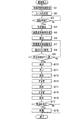
図4は、本実施形態に係る洗濯乾燥機100の送風経路の概略配置を示す斜視図である。図5は、本実施形態に係る洗濯乾燥機100の送風経路の概略配置を示す正面図である。図6は、本実施形態に係る洗濯乾燥機100の左側断面図である。図7は、本実施形態に係る洗濯乾燥機100の概略平面図である。図8は、本実施形態に係る洗濯乾燥機100の内槽、外槽カバー、乾燥ユニット上部ダクトの一部を切り欠いた斜視図である。図4〜7の白抜き矢印、白抜き破線矢印、及び、破線矢印は、洗濯物を加温する空気の流れを模式的に表わす。
[Detailed configuration of each part]
The detailed configuration of each part will be described.
FIG. 4 is a perspective view showing a schematic arrangement of the air blowing path of the washing / drying machine 100 according to the present embodiment. FIG. 5 is a front view showing a schematic arrangement of the air blowing path of the washing / drying machine 100 according to the present embodiment. FIG. 6 is a left sectional view of the washing / drying machine 100 according to the present embodiment. FIG. 7 is a schematic plan view of the washing / drying machine 100 according to the present embodiment. FIG. 8 is a perspective view in which a part of the inner tub, the outer tub cover, and the drying unit upper duct of the washing / drying machine 100 according to the present embodiment is cut out. The white arrows, white dashed arrows, and dashed arrows in FIGS. 4 to 7 schematically represent the flow of air that heats the laundry.

図4に示す様に、乾燥ユニット60は、筐体1の上面に沿って配設された乾燥ユニット上部ダクト61と、筐体1の側面に沿って配設されたエアダクト66とを有している。エアダクト66は、その下部で蛇腹管68を介して外槽10の下部の継手16に接続している。   As shown in FIG. 4, the drying unit 60 includes a drying unit upper duct 61 disposed along the upper surface of the housing 1 and an air duct 66 disposed along the side surface of the housing 1. Yes. The air duct 66 is connected to the joint 16 at the lower part of the outer tub 10 via the bellows pipe 68 at the lower part.

図5〜7に示す様に、エアダクト66は、蛇腹管29bを介して外槽カバー14の空気排出口145に接続している。
図6に示す様に、エアダクト66は、筺体1の後板と外槽10との間に配置される。
As shown in FIGS. 5-7, the air duct 66 is connected to the air discharge port 145 of the outer tank cover 14 via the bellows tube 29b.
As shown in FIG. 6, the air duct 66 is disposed between the rear plate of the housing 1 and the outer tub 10.

図5に示す様に、エアダクト66は、筺体1の内部の後板に沿って上下方向に形成された正面視長方形状の第1の部分66aと、当該第1の部分66aの右側であって上下方向の略中間よりも上に延びる略三角形状部分66dと、当該第1の部分66aの左側にあって上下方向の中間よりも上に延び上部でつながる正面視長方形の第2の部分66bと、当該第2の部分の上の正面視長方形状の第3の部分66cとからなる。   As shown in FIG. 5, the air duct 66 includes a first portion 66 a having a rectangular shape when viewed from the front along the rear plate inside the housing 1, and a right side of the first portion 66 a. A substantially triangular portion 66d extending above substantially the middle in the vertical direction; a second portion 66b having a rectangular shape in front view on the left side of the first portion 66a and extending above the middle in the vertical direction and connected to the upper portion; And a third portion 66c having a rectangular shape in front view above the second portion.

第1の部分66aと第2の部分66bは第1の部分66aの上から約1/5の範囲で接続する。第3の部分66cは第1の部分66aと第2の部分66bに接続する。エアダクト66の上端における左右方向の幅は、下端における左右方向の幅の略2倍が好ましい。エアダクト66の上端は、左側(第1の部分66a側)に冷却水の流下口(不図示)を有し、右側(略三角形状部分66d側)に空気出口(不図示)を有する。
エアダクト66は、奥行き(前後方向の幅)が狭い(図6参照)。
The first portion 66a and the second portion 66b are connected within a range of about 1/5 from the top of the first portion 66a. The third portion 66c is connected to the first portion 66a and the second portion 66b. The width in the left-right direction at the upper end of the air duct 66 is preferably approximately twice the width in the left-right direction at the lower end. The upper end of the air duct 66 has a cooling water outlet (not shown) on the left side (first portion 66a side) and an air outlet (not shown) on the right side (substantially triangular portion 66d side).
The air duct 66 has a narrow depth (width in the front-rear direction) (see FIG. 6).

エアダクト66の第1の部分66aは、下部前側に蛇腹管接続口(不図示)を備え、蛇腹管68と接続する。エアダクト66の第3の部分66cは、前側に蛇腹管接続口(不図示)を備え、蛇腹管29bと接続する(図6、7参照)。略三角形状部分66dは、左側で第1の部分66aと接続する。略三角形状部分66dは、上端で乾燥ユニット上部ダクト61と接続し、乾燥ユニット上部ダクト61との接続部分には、乾燥フィルタ(不図示)が存在する(図5、8参照)。   The first portion 66 a of the air duct 66 includes a bellows tube connection port (not shown) on the lower front side and is connected to the bellows tube 68. The third portion 66c of the air duct 66 includes a bellows tube connection port (not shown) on the front side, and is connected to the bellows tube 29b (see FIGS. 6 and 7). The substantially triangular portion 66d is connected to the first portion 66a on the left side. The substantially triangular portion 66d is connected to the drying unit upper duct 61 at the upper end, and a drying filter (not shown) exists at the connection portion with the drying unit upper duct 61 (see FIGS. 5 and 8).

エアダクト66の内部には、冷水除湿部(不図示)が設けられている。これは、水道水を流してエアダクト66内を流れる空気内の蒸気を結露させるものである。
乾燥フィルタ(不図示)の上部には、乾燥用ファン64(図11参照)と、これを駆動する乾燥用電動機63とが設けられている。又、乾燥用ファン64の後段にはヒータ62が配置され、送風された空気がここで加熱される。
Inside the air duct 66, a cold water dehumidifying section (not shown) is provided. In this case, tap water is allowed to flow and the vapor in the air flowing in the air duct 66 is condensed.
Above the drying filter (not shown), a drying fan 64 (see FIG. 11) and a drying motor 63 for driving the drying fan 64 are provided. In addition, a heater 62 is disposed after the drying fan 64, and the blown air is heated here.

次に、図9に示す外槽カバー14の分解斜視図を参照し、外槽カバー14の詳細構成を説明する。   Next, a detailed configuration of the outer tub cover 14 will be described with reference to an exploded perspective view of the outer tub cover 14 shown in FIG.

(外槽カバー14)
外槽カバー14は、外槽カバー上板14aと外槽カバー下板14bとを有している。外槽カバー上板14aは、円環状に形成された上板周縁部140と、後方部分に形成された弓形平板状の上板後平坦部142と、前方部分に形成された弓形平板状の上板前平坦部143とを有している。そして、これら上板周縁部140、上板後平坦部142および上板前平坦部143に囲まれた略台形状の空間は、洗濯物投入口141になっている。
(Outer tank cover 14)
The outer tank cover 14 includes an outer tank cover upper plate 14a and an outer tank cover lower plate 14b. The outer tank cover upper plate 14a includes an upper plate peripheral portion 140 formed in an annular shape, an arcuate flat plate upper flat plate portion 142 formed in the rear portion, and an arcuate flat plate upper portion formed in the front portion. It has a flat front part 143. A substantially trapezoidal space surrounded by the upper plate peripheral edge portion 140, the upper plate rear flat portion 142, and the upper plate front flat portion 143 is a laundry input port 141.

外槽カバー下板14bは、上板周縁部140よりやや小径の下板周縁部150と、上板後平坦部142に対向する下板後平坦部152と、上板前平坦部143に対向する下板前平坦部153とを有している。下板後平坦部152および下板前平坦部153には、多数の貫通孔158が形成されている。   The outer tub cover lower plate 14 b is a lower plate peripheral portion 150 having a slightly smaller diameter than the upper plate peripheral portion 140, a lower plate rear flat portion 152 facing the upper plate rear flat portion 142, and a lower plate facing the upper plate front flat portion 143. And a front plate flat portion 153. A large number of through-holes 158 are formed in the lower plate rear flat portion 152 and the lower plate front flat portion 153.

外槽カバー上板14aの左側斜め後ろには、側面から法線方向に突出する空気排出口145が形成されている。空気排出口145は、略円筒状に形成された、蛇腹管29bと接続する接続部145aと、上板周縁部140より上に張り出した有底略半円筒状に形成された張出部145bからなる。空気排出口145は、洗濯開始前の洗剤液の液面よりも上の位置に形成されている。なお、洗濯開始前の洗剤液により没することがない洗濯開始前の洗剤液の液面よりも上の位置を非水没位置と称する。非水没位置は、洗剤液の液面との相対位置で決まる。第1実施形態の空気排出口145は、非水没位置に形成されている。   An air discharge port 145 that protrudes in the normal direction from the side surface is formed behind the left side of the outer tank cover upper plate 14a. The air discharge port 145 includes a connection portion 145a connected to the bellows tube 29b formed in a substantially cylindrical shape, and a protruding portion 145b formed in a substantially semi-cylindrical shape with a bottom protruding above the upper plate peripheral edge portion 140. Become. The air discharge port 145 is formed at a position above the liquid level of the detergent liquid before the start of washing. In addition, the position above the liquid level of the detergent liquid before the start of washing that is not immersed by the detergent liquid before the start of washing is referred to as a non-submerged position. The non-submerged position is determined by the relative position to the liquid surface of the detergent liquid. The air discharge port 145 of the first embodiment is formed at a non-submerged position.

蛇腹管29bは、空気排出口145に接続する蛇腹部29b1と、エアダクト66に接続する接続部29b2と、その間の変換部29b3で構成される。変換部29b3は、空気排出口145との接続が略同軸となり、かつ、エアダクト66との接続が略同軸となる角度を備える。   The bellows tube 29b includes a bellows portion 29b1 connected to the air discharge port 145, a connection portion 29b2 connected to the air duct 66, and a conversion portion 29b3 therebetween. The converter 29b3 has an angle at which the connection with the air discharge port 145 is substantially coaxial and the connection with the air duct 66 is substantially coaxial.

外槽カバー14とエアダクト66とを蛇腹管29bで接続することにより、外槽10(洗濯槽)の揺動による変位を吸収することができる。   By connecting the outer tub cover 14 and the air duct 66 with the bellows tube 29b, it is possible to absorb the displacement caused by the swinging of the outer tub 10 (washing tub).

外槽カバー上板14aの上面には、乾燥ユニット60から蛇腹管29dを介して温風を内槽9に導入する温風導入口146と、蛇腹管29c(図3参照)を介して水道水を導入する給水導入口147とが形成されている。導入口146、147は、何れも略円筒状に形成されている。温風導入口146の上端部には、内側の斜め下方向に突出する複数の爪部材146aが形成されている。   On the upper surface of the outer tank cover upper plate 14a, hot water is introduced from the drying unit 60 through the bellows tube 29d into the inner tank 9, and hot water is introduced through the bellows tube 29c (see FIG. 3). And a water supply inlet 147 through which water is introduced. The introduction ports 146 and 147 are all formed in a substantially cylindrical shape. A plurality of claw members 146a are formed at the upper end portion of the hot air inlet 146 so as to protrude obliquely downward on the inside.

外槽カバー上板14aの上面には、洗剤・仕上げ剤容器28(図8参照)が収容されている。洗剤・仕上げ剤容器28の底部には、略円状の孔が形成されている。洗剤・仕上げ剤容器28は、蛇腹管29eを介して外槽カバー14(図2参照)と接続されている。洗剤・仕上げ剤容器28に収容された洗剤や仕上げ剤は、蛇腹管29eを通過して、外槽10の内部に供給される。   A detergent / finishing agent container 28 (see FIG. 8) is accommodated on the upper surface of the outer tank cover upper plate 14a. A substantially circular hole is formed at the bottom of the detergent / finishing agent container 28. The detergent / finishing agent container 28 is connected to the outer tub cover 14 (see FIG. 2) via a bellows tube 29e. The detergent and finishing agent stored in the detergent / finishing agent container 28 is supplied into the outer tub 10 through the bellows tube 29e.

外槽カバー下板14bの側面において、空気排出口145の接続部145aに対応する位置には、切り欠き(図6参照)が形成され、空気排出口145における空気の流通が確保されている。   On the side surface of the outer tank cover lower plate 14b, a notch (see FIG. 6) is formed at a position corresponding to the connecting portion 145a of the air discharge port 145, and air circulation at the air discharge port 145 is ensured.

外槽カバー下板14bにおいて、給水導入口147に対向する位置には、水道水を散水する散水口157が形成されている。又、温風導入口146に対向する位置には、温風導入口146よりもやや小径の円筒状に、温風導入口内筒156が形成されている。   In the outer tub cover lower plate 14b, a water spout 157 for sprinkling tap water is formed at a position facing the water supply inlet 147. A hot air inlet inner cylinder 156 is formed in a cylindrical shape having a slightly smaller diameter than the hot air inlet 146 at a position facing the hot air inlet 146.

そして、温風導入口内筒156の上端部には、ミストメッシュ80が載置される。ミストメッシュ80は、上述したように、金属細線を略半球の網状に織り上げてなるものであるが、ミストメッシュ80の上端周縁部は水平方向に円環状になるよう折り曲げられ、フランジ部81が形成されている。また、ミストメッシュ80の一部は、傾斜する平面状に加工され、メッシュ平面部82が形成されている。   A mist mesh 80 is placed on the upper end of the warm air inlet inner cylinder 156. As described above, the mist mesh 80 is formed by weaving fine metal wires into a substantially hemispherical net shape, but the upper peripheral edge of the mist mesh 80 is bent in an annular shape in the horizontal direction to form a flange portion 81. Has been. A part of the mist mesh 80 is processed into an inclined flat surface, and a mesh flat surface portion 82 is formed.

又、温風導入口内筒156の内側には、傾斜した平面状のミストメッシュ係止板156aが形成されている。ミストメッシュ80を温風導入口内筒156に載置する際には、フランジ部81を温風導入口内筒156の上端部に衝合させる。そして、外槽カバー下板14bと外槽カバー上板14aとを嵌め合わせて一体化させると、温風導入口146の爪部材146aがフランジ部81を上から押圧してミストメッシュ80を固定する。   In addition, an inclined flat mist mesh locking plate 156a is formed inside the warm air inlet inner cylinder 156. When placing the mist mesh 80 on the hot air inlet inner cylinder 156, the flange portion 81 is brought into contact with the upper end of the hot air inlet inner cylinder 156. Then, when the outer tank cover lower plate 14b and the outer tank cover upper plate 14a are fitted and integrated, the claw member 146a of the hot air introduction port 146 presses the flange portion 81 from above to fix the mist mesh 80. .

次に、一体化した外槽カバー14の、ミストメッシュ80の装着部分を含む断面図を図10に示す。   Next, FIG. 10 shows a cross-sectional view of the integrated outer tub cover 14 including the mounting portion of the mist mesh 80.

外槽カバー上板14aと外槽カバー下板14bとの間には、周回方向、及び、洗濯物投入口141の周囲に沿って若干の空間が形成されており、この空間が循環風路18を形成している。貫通孔158から流入した空気は、循環風路18(外槽カバー14の内部)を流れ、しかる後に空気排出口145を介してエアダクト66に排出される(図5、6、9参照)。
前記したように、ミストメッシュ80は、温風導入口内筒156、ミストメッシュ係止板156aおよび爪部材146aによって、外槽カバー14に固定されている。
A slight space is formed between the outer tub cover upper plate 14 a and the outer tub cover lower plate 14 b along the circumference direction and the periphery of the laundry input port 141, and this space is a circulation air passage 18. Is forming. The air flowing in from the through hole 158 flows through the circulation air passage 18 (inside the outer tank cover 14), and is then discharged to the air duct 66 through the air discharge port 145 (see FIGS. 5, 6, and 9).
As described above, the mist mesh 80 is fixed to the outer tank cover 14 by the hot air inlet inner cylinder 156, the mist mesh locking plate 156a, and the claw member 146a.

(乾燥ユニット上部ダクト61)
次に、図11を参照し、乾燥ユニット上部ダクト61の構成を説明する。なお、図11は、乾燥ユニット上部ダクト61の分解斜視図である。
乾燥ユニット上部ダクト61は、上部ダクト上ユニット61aと、上部ダクト下ユニット61bとを有している。上部ダクト下ユニット61bの一端には乾燥フィルタ(不図示)を介して下方から空気を吸入する円状の開口部61cが形成されており、他端には、円筒状の乾燥ダクト22が形成されている。
(Drying unit upper duct 61)
Next, the configuration of the drying unit upper duct 61 will be described with reference to FIG. FIG. 11 is an exploded perspective view of the drying unit upper duct 61.
The drying unit upper duct 61 includes an upper duct upper unit 61a and an upper duct lower unit 61b. A circular opening 61c for sucking air from below is formed at one end of the upper duct lower unit 61b through a drying filter (not shown), and a cylindrical drying duct 22 is formed at the other end. ing.

上部ダクト上ユニット61aにおいて開口部61cに対向する部分には、乾燥用ファン64と、これを駆動する乾燥用電動機63とが装着されている。そして、乾燥ダクト22に対向する部分には、乾燥ダクト22と同心をなすようにしてミストノズル70が上部ダクト上ユニット61aに埋設されている。また、ミストノズル70と、乾燥用ファン64との間には、ヒータ62が配置されている。   A drying fan 64 and a drying electric motor 63 for driving the drying fan 64 are mounted on a portion of the upper duct upper unit 61a facing the opening 61c. A mist nozzle 70 is embedded in the upper duct upper unit 61 a so as to be concentric with the drying duct 22 at a portion facing the drying duct 22. A heater 62 is disposed between the mist nozzle 70 and the drying fan 64.

又、ミストパイプ4bには、ミスト継手71が結合されている。ミストノズル70とミスト継手71との間には、円環状のパッキン73が挿入され、ミスト継手71はネジ72によって上部ダクト上ユニット61aに固定される。これらにより、ミストパイプ4bとミストノズル70とが接続される。また、ミストパイプ4bは、ミストノズル70の上方から給水電磁弁4の後方に向かって配設されている。   A mist joint 71 is coupled to the mist pipe 4b. An annular packing 73 is inserted between the mist nozzle 70 and the mist joint 71, and the mist joint 71 is fixed to the upper duct upper unit 61a by a screw 72. As a result, the mist pipe 4b and the mist nozzle 70 are connected. Further, the mist pipe 4 b is disposed from above the mist nozzle 70 toward the rear of the water supply electromagnetic valve 4.

[通風経路]
初めに、脈動翼盤11による洗い開始前の洗濯物の予熱時における空気の流れについて図を参照しつつ説明する。図4〜6、9、10の白抜き矢印、白抜き破線矢印、及び、破線矢印は、洗濯物を加温する空気の流れを模式的に表わす。
[Ventilation route]
First, the air flow during preheating of the laundry before the start of washing by the pulsating blade 11 will be described with reference to the drawings. 4 to 6, 9, and 10, white arrows, white dashed arrows, and dashed arrows schematically represent the flow of air that heats the laundry.

図9、10に白抜き矢印、白抜き破線矢印で示す様に、内槽9内の空気は、乾燥ユニット60の乾燥用ファン64により、洗濯槽上部の外槽カバー14の貫通孔158から外槽カバー14の内部の循環風路18に取り込まれ(図9参照)、循環風路18を経て空気排出口145に到達する。空気排出口145に到達した空気は、蛇腹管29bを経て(図9参照)、エアダクト66(66c)に流入する(図6参照)。図5に破線矢印で示す様に、エアダクト66に流入した空気は、左から右に(66cから66aを経て66dに)移動して略三角形状部分66dの上部の空気出口(不図示)から排出される。   9 and 10, the air in the inner tub 9 is removed from the through-hole 158 of the outer tub cover 14 in the upper part of the washing tub by the drying fan 64 of the drying unit 60, as indicated by white arrows and white dashed arrows. The air is taken into the circulation air passage 18 inside the tank cover 14 (see FIG. 9) and reaches the air discharge port 145 through the circulation air passage 18. The air that has reached the air outlet 145 passes through the bellows tube 29b (see FIG. 9) and flows into the air duct 66 (66c) (see FIG. 6). As indicated by broken line arrows in FIG. 5, the air flowing into the air duct 66 moves from left to right (from 66c to 66d to 66d) and is discharged from an air outlet (not shown) at the upper portion of the substantially triangular portion 66d. Is done.

図8に示す様に、エアダクト66から排出された空気は、乾燥フィルタ(不図示)を経て、乾燥ユニット上部ダクト61に下側から流入する。図11に示す様に、乾燥ユニット上部ダクト61に流入した空気は、乾燥用ファン64によりヒータ62に送風されて、加熱される。   As shown in FIG. 8, the air discharged from the air duct 66 flows into the drying unit upper duct 61 from below through a drying filter (not shown). As shown in FIG. 11, the air flowing into the drying unit upper duct 61 is blown to the heater 62 by the drying fan 64 and heated.

図11、4に示す様に、乾燥ユニット上部ダクト61のヒータ62で加熱された空気は、乾燥ダクト22、蛇腹管29dを経由し、図9に上下方向の白抜き矢印で示す様に、温風導入口146を経由して、図4に白抜き矢印で示す様に、内槽9内に放出される。図5に白抜き矢印で示す様に、内槽9内に放出された空気は、内槽9内の(脈動翼盤11上の)洗濯物Cに接触して洗濯物を温める。   As shown in FIGS. 11 and 4, the air heated by the heater 62 of the drying unit upper duct 61 passes through the drying duct 22 and the bellows tube 29d, and as shown by the vertical arrows in FIG. As shown by a white arrow in FIG. 4, the air is discharged into the inner tank 9 through the wind inlet 146. As indicated by white arrows in FIG. 5, the air released into the inner tub 9 contacts the laundry C (on the pulsating blade board 11) in the inner tub 9 and warms the laundry.

洗濯物を温めた空気は、内槽9内に洗剤液や水等が張られている場合、外槽10下部の通水通気口(不図示)を通過できずに、内槽9に導入される空気に押されて内槽9や外槽10の内面に沿って上昇する。洗濯槽上部の外槽カバー14(内蓋23)に到達した空気は、図9に白抜き矢印で示す様に、外槽カバー14の貫通孔158に流入する。そして、前記同様の経路を経てヒータ62により再度加熱される。このように空気が循環する。   The air that warms the laundry is introduced into the inner tub 9 without passing through a water vent (not shown) at the bottom of the outer tub 10 when detergent liquid or water is stretched in the inner tub 9. The air rises along the inner surfaces of the inner tank 9 and the outer tank 10 by being pushed by the air. The air that has reached the outer tub cover 14 (inner lid 23) at the upper part of the washing tub flows into the through hole 158 of the outer tub cover 14 as shown by the white arrow in FIG. Then, it is heated again by the heater 62 through the same path. In this way, air circulates.

次に、洗濯物の乾燥時の空気の流れについて説明する。
洗濯物の乾燥時に内槽9内に洗剤液や洗濯水等は存在しないため、乾燥ユニット60の乾燥用ファン64により、空気は外槽10下部の通水通気口(不図示)から排出される。通水通気口から排出された空気は、継手16、蛇腹管68を経由して、エアダクト66に取り込まれる(図4参照)。
Next, the flow of air when the laundry is dried will be described.
Since there is no detergent solution or washing water in the inner tub 9 when the laundry is dried, the air is discharged from a water vent (not shown) at the bottom of the outer tub 10 by the drying fan 64 of the drying unit 60. . The air discharged from the water vent is taken into the air duct 66 through the joint 16 and the bellows pipe 68 (see FIG. 4).

エアダクト66に流入した空気は、第1の部分66aを下から上に移動しつつ内部の冷水除湿部で除湿される。空気は、冷却水との接触から離脱した後、略三角形状部分66dの上部の空気出口(不図示)から排出される(図5参照)。   The air flowing into the air duct 66 is dehumidified by the internal cold water dehumidifying unit while moving from the bottom to the top of the first portion 66a. After leaving the contact with the cooling water, the air is discharged from an air outlet (not shown) at the upper part of the substantially triangular portion 66d (see FIG. 5).

エアダクト66から排出された空気は、洗い開始前の洗濯物の予熱時と同様に移動して、内槽9内に放出される(図6、8、9、11参照)。内槽9内に放出された空気は、内槽9内の洗濯物に接触して洗濯物の水分を水蒸気として蒸発させた後、水蒸気と共に再び通水通気口から排出される。   The air discharged from the air duct 66 moves in the same manner as when the laundry is preheated before the start of washing, and is discharged into the inner tub 9 (see FIGS. 6, 8, 9, and 11). The air released into the inner tub 9 comes into contact with the laundry in the inner tub 9 to evaporate the moisture of the laundry as water vapor, and is then discharged again from the water vent with the water vapor.

洗濯物を乾燥させた空気と水蒸気は、外槽10下部の通水通気口(不図示)から排出されて、前記同様の経路を経てヒータ62により再度加熱される。このように空気が循環する。   The air and water vapor from which the laundry is dried are discharged from a water vent (not shown) at the bottom of the outer tub 10 and are heated again by the heater 62 through the same path. In this way, air circulates.

外槽カバー14に空気排出口145を設けるため、構造的に簡単であり製造が容易である。空気排出口145が洗濯槽の上部に位置するため、又、空気排出口145が洗濯槽に直接開口していないため、水がエアダクト66等に入りにくい。   Since the air outlet 145 is provided in the outer tank cover 14, it is structurally simple and easy to manufacture. Since the air discharge port 145 is located in the upper part of the washing tub, and the air discharge port 145 is not directly open to the washing tub, water hardly enters the air duct 66 and the like.

[ミスト]
図9に示す様に、外槽カバー14において、乾燥ユニット60からの空気の吐出口には、金属細線を略半球の網状に織り上げてなるミストメッシュ80(微細化部材)が装着されている。そして、図8、11に示す様に、ミストメッシュ80の上方には、乾燥ユニット上部ダクト61からミストノズル70が下方に向かって突出している。ミストノズル70は、例えば、内径が約1.5mmの円筒状に構成され、ミストパイプ4bを介して給水電磁弁4に接続されている。
[mist]
As shown in FIG. 9, in the outer tub cover 14, a mist mesh 80 (miniaturized member) formed by weaving fine metal wires into a substantially hemispherical net shape is attached to the air outlet from the drying unit 60. As shown in FIGS. 8 and 11, a mist nozzle 70 protrudes downward from the drying unit upper duct 61 above the mist mesh 80. For example, the mist nozzle 70 is formed in a cylindrical shape having an inner diameter of about 1.5 mm, and is connected to the water supply electromagnetic valve 4 via the mist pipe 4b.

ミストパイプ4bを介して水道水がミストノズル70に供給されると、ミストノズル70から下方に向かって噴射された水道水がミストメッシュ80に衝突し、水道水が微細化(ミスト化)して内槽9内に散布される。従って、ミストノズル70とミストメッシュ80とはミスト散布装置を構成している。ここで、ミストメッシュ80の網の目は、接続口4a(図2参照)の内部に設けられた給水フィルタ(不図示)よりも粗くしておくことが望ましい。これにより、水道水中のゴミによってミストメッシュ80が目詰まりすることを防止できる。又、ミストノズル70の下方にミストメッシュ80を配置したことにより、ミストノズル70から噴射された水は、重力加速度によって加速された上でミストメッシュ80に衝突する。これによって、水の微細化を一層促進することができる。   When tap water is supplied to the mist nozzle 70 via the mist pipe 4b, the tap water sprayed downward from the mist nozzle 70 collides with the mist mesh 80, and the tap water is refined (misted). It is sprayed in the inner tank 9. Therefore, the mist nozzle 70 and the mist mesh 80 constitute a mist spraying device. Here, it is desirable that the mesh of the mist mesh 80 is rougher than a water supply filter (not shown) provided inside the connection port 4a (see FIG. 2). Thereby, it is possible to prevent the mist mesh 80 from being clogged with dust in tap water. Further, since the mist mesh 80 is arranged below the mist nozzle 70, the water sprayed from the mist nozzle 70 is accelerated by the gravitational acceleration and collides with the mist mesh 80. This can further promote the refinement of water.

微細化した水(ミスト)の用途としては、例えば、以下の2点のものが挙げられる。
・用途1:洗濯物を洗濯する初期段階で、ミストを散布することによって洗濯物を湿らせ、洗濯物の汚れを落ちやすくする。
・用途2:洗濯後の洗濯物を乾燥させる際、ミストを散布することによって洗濯物を湿らせつつ洗濯物に風を当てることにより、洗濯物のしわを取る。
Examples of the use of fine water (mist) include the following two points.
-Use 1: At the initial stage of washing the laundry, the laundry is moistened by spraying mist to make it easier to clean the laundry.
Application 2: When drying laundry after washing, the laundry is wrinkled by applying wind to the laundry while moistening the laundry by spraying mist.

[制御装置]
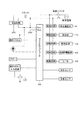
図12は、本実施形態に係る洗濯乾燥機の電気的構成を示すブロック図である。
本実施形態に係る洗濯乾燥機100は、マイコン40(マイクロコンピュータ)で制御される。
マイコン40は、操作ボタンスイッチ6に接続される操作ボタン入力回路、水位センサ、温度センサと接続され、使用者のボタン操作や洗濯工程、乾燥工程での各種情報信号を受ける。
又、マイコン40は、駆動回路に接続され、給水電磁弁4、排水弁15、駆動装置13、乾燥用電動機63、ヒータ62等に接続され、これらの開閉や回転、通電を制御する。
又、マイコン40は、使用者に洗濯乾燥機100の動作状態を知らせるための操作パネル8の表示器や発光ダイオード、ブザー等に接続される。
[Control device]
FIG. 12 is a block diagram showing an electrical configuration of the washing / drying machine according to the present embodiment.
The washing / drying machine 100 according to this embodiment is controlled by a microcomputer 40 (microcomputer).
The microcomputer 40 is connected to an operation button input circuit connected to the operation button switch 6, a water level sensor, and a temperature sensor, and receives various information signals in the user's button operation, washing process, and drying process.
The microcomputer 40 is connected to a drive circuit and connected to the water supply electromagnetic valve 4, the drain valve 15, the drive device 13, the drying motor 63, the heater 62, and the like, and controls opening / closing, rotation, and energization thereof.
The microcomputer 40 is connected to a display, a light emitting diode, a buzzer, etc. of the operation panel 8 for notifying the user of the operation state of the washing / drying machine 100.

[洗濯乾燥機の動作]
次に、本実施形態に係る洗濯乾燥機の動作について、これまで説明した図を適宜参照しつつ、図13を用いて説明する。
図13は、本実施形態に係る洗濯乾燥機の制御を示すフローチャートである。
[Operation of washing dryer]
Next, the operation of the washing and drying machine according to the present embodiment will be described with reference to FIG. 13 with reference to the drawings described so far.
FIG. 13 is a flowchart showing control of the washing / drying machine according to the present embodiment.

マイコン40は、使用者により電源スイッチ5が押されて電源が投入されることにより、洗濯乾燥機100の状態確認及び初期設定を行う(ステップS1)。   The microcomputer 40 confirms the state of the washing / drying machine 100 and performs initial setting when the user presses the power switch 5 to turn on the power (step S1).

マイコン40は、操作パネル8の表示器を点灯させ、使用者により操作された操作ボタンスイッチに従って洗濯/乾燥コースを設定する(ステップS2)。なお、設定がない場合には、標準の洗濯/乾燥コースまたは前回に実行された洗濯/乾燥コースを自動的に設定する。例えば、操作ボタンスイッチが使用者により操作された場合には、「洗濯乾燥コース」を設定する。   The microcomputer 40 turns on the display of the operation panel 8 and sets the washing / drying course according to the operation button switch operated by the user (step S2). If there is no setting, the standard washing / drying course or the previously executed washing / drying course is automatically set. For example, when the operation button switch is operated by the user, “washing and drying course” is set.

マイコン40は、操作ボタンスイッチの操作により運転開始が指示されたか、否かを判定する(ステップS3)。
マイコン40は、操作ボタンスイッチの操作により運転開始が指示されるまでステップS3を繰り返し(ステップS3でNo)、運転開始が指示さされたら、ステップS4に進む(ステップS3でYes)。
The microcomputer 40 determines whether or not an operation start is instructed by operating the operation button switch (step S3).
The microcomputer 40 repeats step S3 until the start of operation is instructed by operating the operation button switch (No in step S3). When the start of operation is instructed, the process proceeds to step S4 (Yes in step S3).

マイコン40は、まず、布量センシングを実施する(ステップS4)。布量センシングは、例えば、内槽9を低速で回転させ、あるいは規定の回転速度まで加速させ、そのときの駆動装置13の電動機の電流値から測定する。
マイコン40は、布量センシングで算出した洗濯物の重量に基づいて、表示器に洗濯/乾燥が終了するまでの時間や洗剤量を表示する。
これにより、使用者は蓋体2aを開けて、適量の液体洗剤を洗剤・仕上げ剤容器28に入れる。又、使用者は、必要に応じて柔軟仕上げ剤を洗剤・仕上げ剤容器28に入れる。
The microcomputer 40 first performs cloth amount sensing (step S4). In the cloth amount sensing, for example, the inner tub 9 is rotated at a low speed or accelerated to a specified rotational speed and measured from the current value of the electric motor of the driving device 13 at that time.
The microcomputer 40 displays the time until the washing / drying is completed and the amount of detergent based on the weight of the laundry calculated by the cloth amount sensing.
As a result, the user opens the lid 2 a and puts an appropriate amount of liquid detergent into the detergent / finishing agent container 28. Further, the user puts the softening finish into the detergent / finishing agent container 28 as necessary.

マイコン40は、高濃度洗剤液を生成する(ステップS5)。
マイコン40は、給水電磁弁4を開き、洗剤・仕上げ剤容器28に給水し、固体洗剤を溶かし、又は、液体洗剤を希釈して、高濃度洗剤液を生成する。なお、生成された高濃度洗剤液は、洗濯槽に溜められる(図2参照)。
The microcomputer 40 generates a high concentration detergent solution (Step S5).
The microcomputer 40 opens the water supply electromagnetic valve 4, supplies water to the detergent / finishing agent container 28, dissolves the solid detergent, or dilutes the liquid detergent to generate a high-concentration detergent liquid. In addition, the produced | generated high concentration detergent liquid is stored in a washing tub (refer FIG. 2).

マイコン40は、給水電磁弁4を開き、高濃度洗剤液の循環に必要な量を、又は、脈動翼盤11の上まで給水する(ステップS6)。   The microcomputer 40 opens the water supply electromagnetic valve 4 and supplies the water necessary for the circulation of the high-concentration detergent solution or up to the top of the pulsating blade board 11 (step S6).

マイコン40は、駆動装置13の電動機を回転させて、脈動翼盤11の裏羽根11bで内槽9内を攪拌する。裏羽根11bにより攪拌された高濃度洗剤液は、内槽9の内周面に形成された循環流路9cを上昇して、吐出口9dから内槽9内に吐出される。吐出口9dは内槽9の上部に位置することから、高濃度洗剤液は、洗濯物の上部から洗濯物に散布されて、洗濯物に浸透する(ステップS7)。   The microcomputer 40 rotates the electric motor of the driving device 13 and stirs the inside of the inner tank 9 with the back blade 11 b of the pulsating blade 11. The high-concentration detergent liquid stirred by the back blade 11b ascends the circulation channel 9c formed on the inner peripheral surface of the inner tank 9, and is discharged into the inner tank 9 from the discharge port 9d. Since the discharge port 9d is located in the upper part of the inner tub 9, the high-concentration detergent liquid is sprayed on the laundry from the upper part of the laundry and penetrates into the laundry (step S7).

マイコン40は、給水電磁弁4を開き、乾燥ユニット60の乾燥用ファン64を回転させ、ヒータ62を作動させて、高速の風を内槽9内に吹き込むと共に、ミストパイプ4bを介してミストノズル70に水道水を供給し、水道水を温水ミスト化して洗濯物に散布する(ステップS8)。   The microcomputer 40 opens the water supply electromagnetic valve 4, rotates the drying fan 64 of the drying unit 60, operates the heater 62, blows high-speed air into the inner tank 9, and mist nozzles via the mist pipe 4 b. Tap water is supplied to 70, and the tap water is converted into hot water mist and sprayed on the laundry (step S8).

マイコン40は、洗濯物の温度を測定し、所定の温度まで到達していない場合は、ステップS7に戻り、高濃度洗剤液の散布と温水ミストの散布を繰り返す(ステップS9でNo)。マイコン40は、洗濯物の温度を測定し、所定の温度まで到達した場合は、ステップS10に進む(ステップS9でYes)。   The microcomputer 40 measures the temperature of the laundry, and if the temperature has not reached the predetermined temperature, the microcomputer 40 returns to step S7 and repeats the spraying of the high-concentration detergent solution and the warm water mist (No in step S9). The microcomputer 40 measures the temperature of the laundry, and proceeds to step S10 if the temperature reaches the predetermined temperature (Yes in step S9).

マイコン40は、洗い運転を行うために、外槽2に規定の水位まで給水する(ステップS10)。
マイコン40は、給水電磁弁4を開き、蛇腹管29cを経て給水導入口147より内槽9内に給水する。又、マイコン40は、給水電磁弁4を開き、洗剤・仕上げ剤容器28に給水して、洗剤・仕上げ剤容器28を洗浄する。洗剤・仕上げ剤容器28から流れた水は、外槽10と内槽9の間に流れる(ステップS10)。
In order to perform the washing operation, the microcomputer 40 supplies water to the outer tub 2 to a specified water level (step S10).
The microcomputer 40 opens the water supply electromagnetic valve 4 and supplies water into the inner tank 9 from the water supply inlet 147 through the bellows tube 29c. Further, the microcomputer 40 opens the water supply electromagnetic valve 4 and supplies water to the detergent / finishing agent container 28 to wash the detergent / finishing agent container 28. The water that flows from the detergent / finishing agent container 28 flows between the outer tub 10 and the inner tub 9 (step S10).

マイコン40は、洗い運転を実行する。
マイコン40は、電動機13aを回転させて、内槽9や脈動翼盤11を低速で正逆方向に交互に回転させながら、洗いを行う(ステップS11)。
The microcomputer 40 performs a washing operation.
The microcomputer 40 performs washing while rotating the electric motor 13a and alternately rotating the inner tank 9 and the pulsating blade 11 in the forward and reverse directions at a low speed (step S11).

マイコン40は、洗濯物から洗い水を除くために、排水・脱水運転を行う。
マイコン40は、排水弁16を開き、外槽10内の洗い水を排水後、駆動装置13の電動機を回転させ、内槽9を高速で回転させることにより、洗濯物を遠心脱水する(ステップS12)。
The microcomputer 40 performs drainage / dehydration operation in order to remove washing water from the laundry.
The microcomputer 40 opens the drain valve 16 and drains the washing water in the outer tub 10, and then rotates the electric motor of the driving device 13 to rotate the inner tub 9 at a high speed, thereby centrifugally dehydrating the laundry (step S 12). ).

マイコン40は、排水弁16を閉じ、給水電磁弁4を開き、所定の水位まで外槽10にすすぎ水を給水する。
所定の水位まで給水すると、マイコン40は、給水電磁弁4を閉じ、駆動装置13の電動機を駆動して回転ドラム3を低速で正逆方向に交互に回転させながら、洗濯物をすすぐ「濯ぎ」運転を実行する(ステップS13)。
The microcomputer 40 closes the drain valve 16 and opens the water supply electromagnetic valve 4 to supply rinse water to the outer tub 10 to a predetermined water level.
When the water is supplied to a predetermined water level, the microcomputer 40 closes the water supply electromagnetic valve 4 and drives the electric motor of the driving device 13 to alternately rotate the rotating drum 3 in the forward and reverse directions at a low speed, thereby “rinsing” the laundry. Operation is executed (step S13).

濯ぎ運転終了後、マイコン40は、排水弁16を開き、外槽10内のすすぎ水を排水した後、駆動装置13の電動機を駆動して内槽9を高速で回転させることにより、洗濯物を遠心脱水する(ステップS14)。   After the rinsing operation is finished, the microcomputer 40 opens the drain valve 16 and drains the rinse water in the outer tub 10, and then drives the electric motor of the driving device 13 to rotate the inner tub 9 at a high speed, thereby washing the laundry. Centrifugal dehydration is performed (step S14).

マイコン40は、排水弁16を閉じ、給水電磁弁4を開き、所定の水位まで外槽10にすすぎ水を給水する。
所定の水位まで給水すると、マイコン40は、給水電磁弁4を閉じ、駆動装置13の電動機を駆動して回転ドラム3を低速で正逆方向に交互に回転させながら、洗濯物をすすぐ「濯ぎ」運転を実行する(ステップS15)。
The microcomputer 40 closes the drain valve 16 and opens the water supply electromagnetic valve 4 to supply rinse water to the outer tub 10 to a predetermined water level.
When the water is supplied to a predetermined water level, the microcomputer 40 closes the water supply electromagnetic valve 4 and drives the electric motor of the driving device 13 to alternately rotate the rotating drum 3 in the forward and reverse directions at a low speed, thereby “rinsing” the laundry. Operation is executed (step S15).

濯ぎ運転終了後、マイコン40は、排水弁16を開き、外槽10内のすすぎ水を排水した後、駆動装置13の電動機を駆動して内槽9を高速で回転させることにより、洗濯物を遠心脱水する(ステップS16)。   After the rinsing operation is finished, the microcomputer 40 opens the drain valve 16 and drains the rinse water in the outer tub 10, and then drives the electric motor of the driving device 13 to rotate the inner tub 9 at a high speed, thereby washing the laundry. Centrifugal dehydration is performed (step S16).

マイコン40は、ステップS2で選択されたコースが乾燥を含むコースであるか否かを判定する(ステップS17)。
ステップS2で選択されたコースが乾燥を含むコースである場合には(ステップS17でYes)、ステップS18に進み、乾燥運転を実行する(ステップS17)。
ステップS2で選択されたコースが乾燥を含まないコースであるである場合には(ステップS17でNo)、運転を終了する(ステップS17)。
The microcomputer 40 determines whether or not the course selected in step S2 is a course including drying (step S17).
When the course selected in Step S2 is a course including drying (Yes in Step S17), the process proceeds to Step S18 and a drying operation is performed (Step S17).
If the course selected in step S2 is a course that does not include drying (No in step S17), the operation is terminated (step S17).

乾燥運転では、マイコン40は、内槽9を低速で回転させながら、乾燥ユニット60の乾燥用ファン64を高速回転で駆動し、ヒータ62に通電して、高速の温風を内槽9内に吹き込み洗濯物の温度を上昇させ、洗濯物から水分を蒸発させる。又、マイコン40は、給水電磁弁4を開き、エアダクト66の冷水除湿部に冷却水を供給する。洗濯物から蒸発した水分を含む高温多湿の空気は、エアダクト66の冷水除湿部で除湿される。
乾燥の完了の検知は、温度センサ(不図示)で行い、マイコン40は洗濯物の乾燥を検知したら乾燥運転を終了する(ステップS18)。
In the drying operation, the microcomputer 40 drives the drying fan 64 of the drying unit 60 at a high speed while rotating the inner tank 9 at a low speed, energizes the heater 62, and causes high-speed hot air to flow into the inner tank 9. Raise the temperature of the blown laundry and evaporate moisture from the laundry. The microcomputer 40 opens the water supply electromagnetic valve 4 and supplies cooling water to the cold water dehumidifying part of the air duct 66. The hot and humid air containing moisture evaporated from the laundry is dehumidified by the cold water dehumidifying portion of the air duct 66.
The completion of drying is detected by a temperature sensor (not shown), and the microcomputer 40 ends the drying operation when it detects the drying of the laundry (step S18).

本実施形態に係る洗濯乾燥機100は、内槽9に循環流路9cを備えることにより、高濃度洗剤液を循環させるポンプを備えなくとも高濃度洗剤液を循環させることができる。本実施形態に係る洗濯乾燥機100は、洗濯槽(外槽10)とエアダクト66とを接続して空気の循環経路を確保することにより、高濃度洗剤液を循環させるポンプを備えなくとも洗濯物を温風で温めることができる。又、高速の温風で水を温水ミスト化し、拡散噴霧して洗濯物に吹き付けるので、高濃度洗剤液の散布とあわせ、洗濯物の隙間に付着した汚れや内槽9の奥の洗濯物にも満遍なく行き渡り、汚れをとれやすい状態にできる。そして、給水を行い洗い運転をするので、洗浄力を向上させることができる。
本実施形態に係る洗濯乾燥機100は、循環ポンプよりも構造が簡単な蛇腹管を備えて空気の循環経路を確保し、又、洗濯乾燥機が備える送風手段を使用して水を温水ミスト化しているので、コストアップすることなく、安価な方法で、高い洗浄力を得られる洗濯乾燥機を提供することができる。
The washing / drying machine 100 according to this embodiment can circulate the high-concentration detergent liquid by providing the inner tub 9 with the circulation flow path 9c without providing a pump that circulates the high-concentration detergent liquid. The washing / drying machine 100 according to the present embodiment connects the washing tub (outer tub 10) and the air duct 66 to ensure an air circulation path, and thus does not include a pump for circulating a high-concentration detergent solution. Can be warmed with warm air. Moreover, water is made into hot water mist with high-speed hot air, and sprayed on the laundry by spreading and spraying it on the laundry, along with the spraying of high-concentration detergent solution, on the dirt stuck in the laundry and the laundry behind the inner tub 9 Evenly spreads out and makes it easy to remove dirt. And since a washing operation is performed by supplying water, the detergency can be improved.
The washing / drying machine 100 according to the present embodiment includes a bellows tube having a simpler structure than the circulation pump to secure an air circulation path, and also uses water blowing means provided in the washing / drying machine to convert water into hot water mist. Therefore, it is possible to provide a washing / drying machine that can obtain a high detergency by an inexpensive method without increasing the cost.

なお、濯ぎ(ステップS13からステップS16)は、図13に示すフローチャートでは、2回行っているが、「給水―濯ぎ―脱水」の組み合わせを1回、又は、複数回行ってもよい。   Note that the rinsing (step S13 to step S16) is performed twice in the flowchart shown in FIG. 13, but the combination of “water supply—rinsing—dehydration” may be performed once or a plurality of times.

<第2実施形態>
これまで説明した図を適宜参照しつつ、第2実施形態を説明する。
図14は、第2実施形態に係る洗濯乾燥機の概略構造を示す模式図である。
第2実施形態は、外槽10の上部後方側面に空気排出口101を設け、蛇腹管292によりエアダクト66と接続した洗濯乾燥機である。
Second Embodiment
The second embodiment will be described with reference to the drawings described so far as appropriate.
FIG. 14 is a schematic diagram illustrating a schematic structure of the washing / drying machine according to the second embodiment.
The second embodiment is a washing and drying machine provided with an air discharge port 101 on the upper rear side surface of the outer tub 10 and connected to the air duct 66 by a bellows tube 292.

第2実施形態に係る外槽10は、上部後方側面のエアダクト66に対向する位置に空気排出口101を備える。空気排出口101の位置は、外槽10とエアダクト66の距離が最短となる位置が好ましい。空気排出口101は、洗濯開始前の洗剤液の液面よりも上の位置、つまり非水没位置に形成されている。   The outer tub 10 according to the second embodiment includes an air discharge port 101 at a position facing the air duct 66 on the upper rear side surface. The position of the air discharge port 101 is preferably a position where the distance between the outer tub 10 and the air duct 66 is the shortest. The air discharge port 101 is formed at a position above the level of the detergent liquid before the start of washing, that is, at a non-submerged position.

蛇腹管292は、例えば第1実施形態の29bと同様に、空気排出口101に接続する蛇腹部と、エアダクト66に接続する接続部と、その間の変換部で構成される。変換部は、空気排出口101との接続が同軸となり、エアダクト66との接続が同軸となる角度を備える。   The bellows tube 292 includes a bellows part connected to the air discharge port 101, a connection part connected to the air duct 66, and a conversion part between them, for example, as in 29b of the first embodiment. The conversion unit has an angle at which the connection with the air discharge port 101 is coaxial and the connection with the air duct 66 is coaxial.

[通風経路]
第2実施形態における通風経路を、図14を参考にしつつ説明する。
内槽9内の空気は、乾燥ユニット60の乾燥用ファン64により、外槽10の上部後方側面の空気排出口101から蛇腹管292を経て、エアダクト66(66c)に流入する(図14参照)。エアダクト66に流入した空気は、左から右に(66cから66aを経て66dに)移動して略三角形状部分66dの上部の空気出口(不図示)から排出される(図5参照)。
[Ventilation route]
The ventilation path in 2nd Embodiment is demonstrated referring FIG.
The air in the inner tank 9 flows into the air duct 66 (66c) from the air discharge port 101 on the upper rear side surface of the outer tank 10 through the bellows tube 292 by the drying fan 64 of the drying unit 60 (see FIG. 14). . The air flowing into the air duct 66 moves from left to right (from 66c to 66a to 66d) and is discharged from an air outlet (not shown) at the upper portion of the substantially triangular portion 66d (see FIG. 5).

エアダクト66から排出された空気は、第1実施形態と同様の経路で乾燥ユニット60に流入して乾燥される。乾燥した空気は、第1実施形態と同様の経路で内槽9内に放出される(図4、5、9、11参照)。内槽9内に放出された空気は、内槽9内の(脈動翼盤11上の)洗濯物Cに接触して洗濯物Cを温める。   The air discharged from the air duct 66 flows into the drying unit 60 through the same path as in the first embodiment and is dried. The dried air is discharged into the inner tank 9 through the same route as in the first embodiment (see FIGS. 4, 5, 9, and 11). The air released into the inner tub 9 comes into contact with the laundry C (on the pulsating blade 11) in the inner tub 9 and warms the laundry C.

洗濯物Cを温めた空気は、内槽9内に洗剤液や水等が張られている場合、外槽10下部の通水通気口(不図示)を通過できずに、内槽9や貫通穴9aを通過して外槽10の内面に沿って上昇する。洗濯槽上部の内蓋23や外槽カバー14に到達した空気は、内蓋23(図2参照)等の内面に沿って移動し、外槽10の上部後方側面の空気排出口101に到達する。そして、空気は、前記同様、蛇腹管292を経て、ヒータ62により再度加熱される。このように空気が循環する。   When the detergent C, water, or the like is stretched in the inner tub 9, the air that warms the laundry C cannot pass through the water vent (not shown) at the bottom of the outer tub 10, and passes through the inner tub 9 or through the inner tub 9. It passes along the hole 9a and rises along the inner surface of the outer tub 10. The air that has reached the inner lid 23 and the outer tub cover 14 at the upper part of the washing tub moves along the inner surface of the inner lid 23 (see FIG. 2) and reaches the air discharge port 101 on the upper rear side surface of the outer tub 10. . Then, the air is heated again by the heater 62 through the bellows tube 292 as described above. In this way, air circulates.

洗濯物の乾燥時の空気の流れは、第1実施形態と同様である。   The flow of air when the laundry is dried is the same as in the first embodiment.

空気排出口101を外槽10の上部後方側面に設けることにより、外槽10からエアダクト66までの空気の移動距離が短くなり、送風抵抗も小さくなるため、エネルギ効率や乾燥効率が向上する。   By providing the air discharge port 101 on the upper rear side surface of the outer tub 10, the air moving distance from the outer tub 10 to the air duct 66 is shortened and the blowing resistance is also reduced, so that energy efficiency and drying efficiency are improved.

<第3実施形態>
これまで説明した図を適宜参照しつつ、第3実施形態を説明する。
図15は、第3実施形態に係る洗濯乾燥機の概略構造を示す模式図である。
第3実施形態は、洗剤・仕上げ剤容器28の側面に空気排出口28aを設けて、接続管681によりエアダクト66と接続した洗濯乾燥機である。
<Third Embodiment>
The third embodiment will be described with reference to the drawings described so far as appropriate.
FIG. 15 is a schematic diagram illustrating a schematic structure of the washing / drying machine according to the third embodiment.
The third embodiment is a washing / drying machine in which an air discharge port 28 a is provided on the side surface of the detergent / finishing agent container 28 and connected to the air duct 66 by a connection pipe 681.

空気排出口28aは、洗濯槽よりも上に位置する洗剤・仕上げ剤容器28に設けられており、洗濯開始前の洗剤液の液面よりも上の位置に形成されている。第3実施形態の空気排出口28aは、非水没位置に形成されている。   The air discharge port 28a is provided in the detergent / finishing agent container 28 located above the washing tub, and is formed at a position above the level of the detergent liquid before the start of washing. The air discharge port 28a of the third embodiment is formed at a non-submerged position.

第3実施形態に係る洗剤・仕上げ剤容器28とエアダクト66とは、接続管681で接続される。洗剤・仕上げ剤容器28と外槽カバー14が蛇腹管で接続されているため、第3実施形態は、エアダクト66と接続管681との間に外槽10(洗濯槽)の揺動による変位を吸収する蛇腹管や蛇腹部は備えなくてもよい。   The detergent / finishing agent container 28 and the air duct 66 according to the third embodiment are connected by a connecting pipe 681. Since the detergent / finishing agent container 28 and the outer tub cover 14 are connected by a bellows tube, in the third embodiment, the displacement caused by the swinging of the outer tub 10 (washing tub) is between the air duct 66 and the connection tube 681. Absorbing bellows tubes and bellows portions may not be provided.

[通風経路]
第3実施形態における通風経路を、図15を参考にしつつ説明する。
内槽9内の空気は、乾燥ユニット60の乾燥用ファン64により、洗剤・仕上げ剤容器28の空気排出口28aから接続管681を経て、エアダクト66(66c)に流入する(図15参照)。エアダクト66に流入した空気は、第1実施形態、第2実施形態と同様の手段、同様の経路で乾燥されて、内槽9内に放出される(図4、5、9、11参照)。内槽9内に放出された空気は、内槽9内の(脈動翼盤11上の)洗濯物Cに接触して洗濯物Cを温める。
[Ventilation route]
The ventilation path in 3rd Embodiment is demonstrated referring FIG.
The air in the inner tub 9 flows into the air duct 66 (66c) from the air discharge port 28a of the detergent / finishing agent container 28 through the connecting pipe 681 by the drying fan 64 of the drying unit 60 (see FIG. 15). The air that has flowed into the air duct 66 is dried by the same means and the same route as in the first and second embodiments, and discharged into the inner tank 9 (see FIGS. 4, 5, 9, and 11). The air released into the inner tub 9 comes into contact with the laundry C (on the pulsating blade 11) in the inner tub 9 and warms the laundry C.

洗濯物Cを温めた空気は、内槽9内に洗剤液や水等が張られている場合、外槽10下部の通水通気口(不図示)を通過できずに、内槽9や貫通穴9aを通過して外槽10の内面に沿って上昇する。洗濯槽上部の外槽カバー14(内蓋23)に到達した空気は、内蓋23(図2参照)等の内面に沿って移動し、蛇腹管29eから洗剤・仕上げ剤容器28に流入する。そして、前記同様の経路を経てヒータ62により再度加熱される。このように空気が循環する。   When the detergent C, water, or the like is stretched in the inner tub 9, the air that warms the laundry C cannot pass through the water vent (not shown) at the bottom of the outer tub 10, and passes through the inner tub 9 or through the inner tub 9. It passes along the hole 9a and rises along the inner surface of the outer tub 10. The air that has reached the outer tub cover 14 (inner lid 23) at the upper part of the washing tub moves along the inner surface of the inner lid 23 (see FIG. 2) and flows into the detergent / finishing agent container 28 from the bellows tube 29e. Then, it is heated again by the heater 62 through the same path. In this way, air circulates.

洗濯物の乾燥時の空気の流れは、第1実施形態と同様である。   The flow of air when the laundry is dried is the same as in the first embodiment.

洗剤・仕上げ剤容器28とエアダクト66とを接続管681で接続することにより、外槽カバー14や外槽10に空気排出口を設けるよりも容易に空気排出口を設けることができ、製造コストの削減を図ることができる。蛇腹管よりも構造が単純な接続管とすることで耐久性の向上も見込まれる。温風導入口146と空気排出口を離すことができるため、洗濯物の加温効率の向上が見込まれる。接続管の配置の自由度も高いため、製造が容易に行える。   By connecting the detergent / finishing agent container 28 and the air duct 66 with the connecting pipe 681, it is possible to provide an air outlet more easily than providing the air outlet in the outer tank cover 14 or the outer tank 10, and the manufacturing cost is reduced. Reduction can be achieved. Durability is also expected to be improved by using a connecting tube that has a simpler structure than the bellows tube. Since the hot air introduction port 146 and the air discharge port can be separated from each other, the heating efficiency of the laundry is expected to be improved. Since the degree of freedom of the arrangement of the connecting pipe is also high, manufacturing can be easily performed.

以上、本発明に洗濯乾燥機について実施の形態を示して詳細に説明した。なお、本発明の内容は、前記実施形態に限定されず、その趣旨を逸脱しない範囲内において適宜追加・削除・変更等することができることはいうまでもない。   As described above, the present invention has been described in detail with reference to the embodiment of the washing and drying machine. Needless to say, the contents of the present invention are not limited to the above-described embodiment, and can be appropriately added, deleted, changed, and the like without departing from the spirit of the present invention.

9 内槽(洗濯槽)
9c 循環流路
10 外槽(洗濯槽)
101 空気排出口(吸込み口)
11 脈動翼盤
14 外槽カバー(洗濯槽カバー)
145 空気排出口(吸込み口)
146 温風導入口(吹出し口)
16 継手
18 循環風路
22 乾燥ダクト
28 洗剤・仕上げ剤容器
29b 蛇腹管(通風路)
29c、d、e 蛇腹管
292 蛇腹管(通風路)
60 乾燥ユニット
62 ヒータ
66 エアダクト(通風路)
68 蛇腹管
681 接続管(通風路)
100 洗濯乾燥機
C 洗濯物
9 Inner tub (washing tub)
9c Circulation channel 10 Outer tub (washing tub)
101 Air outlet (suction port)
11 Pulsating blade 14 Outer tank cover (washing tank cover)
145 Air outlet (suction port)
146 Hot air inlet (outlet)
16 Joint 18 Circulating air path 22 Drying duct 28 Detergent / finishing agent container 29b Bellows tube (ventilation path)
29c, d, e Bellows tube 292 Bellows tube (ventilation path)
60 Drying unit 62 Heater 66 Air duct (ventilation path)
68 Bellows tube 681 Connection tube (ventilation path)
100 Washer / dryer C Laundry

Claims (4)

洗濯物を収容する洗濯槽と、
入口と出口を有し、前記入口から取り込んだ前記洗濯槽内の空気を乾燥させて前記出口から排出する乾燥ユニットと、
前記乾燥ユニットの出口と接続され、前記乾燥ユニットによって乾燥された空気を前記洗濯槽の上方から吹き出す吹出し口と、
前記乾燥ユニットの入口と接続され、前記乾燥ユニットに導く前記洗濯槽内の空気を前記洗濯槽の非水没位置から吸い込む吸込み口と、を備え、
前記非水没位置は、洗濯開始前の洗剤液の液面よりも上の位置であり、
前記吸込み口から吸い込んだ前記洗濯槽内の空気を前記乾燥ユニットで乾燥させて前記吹出し口から吹き出して循環させることを特徴とする洗濯乾燥機。
A laundry tub for storing laundry;
A drying unit having an inlet and an outlet, for drying air in the washing tub taken in from the inlet and discharging the air from the outlet;
An outlet connected to the outlet of the drying unit and for blowing out the air dried by the drying unit from above the washing tub;
A suction port that is connected to an inlet of the drying unit and sucks the air in the washing tub leading to the drying unit from a non-submerged position of the washing tub;
The non-submerged position is a position above the level of the detergent liquid before the start of washing,
A laundry dryer, wherein the air in the washing tub sucked from the suction port is dried by the drying unit and blown out from the outlet and circulated.
前記吸込み口と前記入口とを接続し、前記洗濯槽内の空気を前記乾燥ユニットに導く通風路を備えることを特徴とする請求項1に記載の洗濯乾燥機。   The washing / drying machine according to claim 1, further comprising a ventilation path that connects the suction port and the inlet and guides air in the washing tub to the drying unit. 前記吸込み口は、前記洗濯槽の側面又は前記洗濯槽の上部開口を閉塞する洗濯槽カバーの側面に備わることを特徴とする請求項1又は請求項2に記載の洗濯乾燥機。   The washing / drying machine according to claim 1 or 2, wherein the suction port is provided on a side surface of the washing tub or a side surface of a washing tub cover that closes an upper opening of the washing tub. 前記吸込み口は、前記洗濯槽に洗剤や仕上げ剤を投入するための容器に備わることを特徴とする請求項1又は請求項2に記載の洗濯乾燥機。   The washing / drying machine according to claim 1 or 2, wherein the suction port is provided in a container for putting a detergent or a finishing agent into the washing tub.
JP2016081725A 2016-04-15 2016-04-15 Washing and drying machine Pending JP2017189484A (en)

Priority Applications (3)

Application Number Priority Date Filing Date Title
JP2016081725A JP2017189484A (en) 2016-04-15 2016-04-15 Washing and drying machine
CN201710214193.4A CN107299493B (en) 2016-04-15 2017-03-30 Washing and drying machine
TW106112257A TWI649474B (en) 2016-04-15 2017-04-12 Washing and drying machine

Applications Claiming Priority (1)

Application Number Priority Date Filing Date Title
JP2016081725A JP2017189484A (en) 2016-04-15 2016-04-15 Washing and drying machine

Publications (1)

Publication Number Publication Date
JP2017189484A true JP2017189484A (en) 2017-10-19

Family

ID=60085519

Family Applications (1)

Application Number Title Priority Date Filing Date
JP2016081725A Pending JP2017189484A (en) 2016-04-15 2016-04-15 Washing and drying machine

Country Status (3)

Country Link
JP (1) JP2017189484A (en)
CN (1) CN107299493B (en)
TW (1) TWI649474B (en)

Citations (9)

* Cited by examiner, † Cited by third party
Publication number Priority date Publication date Assignee Title
JP2000325694A (en) * 1999-05-19 2000-11-28 Sharp Corp Drum type washing machine
JP2006198149A (en) * 2005-01-20 2006-08-03 Toshiba Corp Washing machine with drying function
JP2008000476A (en) * 2006-06-23 2008-01-10 Mitsubishi Electric Corp Washing machine
JP2008259627A (en) * 2007-04-11 2008-10-30 Toshiba Corp Washing machine
JP2012000312A (en) * 2010-06-18 2012-01-05 Sharp Corp Washer-dryer
JP2012075525A (en) * 2010-09-30 2012-04-19 Sharp Corp Washing and drying machine
WO2014129363A1 (en) * 2013-02-20 2014-08-28 シャープ株式会社 Washing machine, washing method, and washer dryer
JP2015042208A (en) * 2013-08-26 2015-03-05 株式会社東芝 Clothes dryer
JP2015089473A (en) * 2013-11-07 2015-05-11 株式会社東芝 Washing machine

Family Cites Families (11)

* Cited by examiner, † Cited by third party
Publication number Priority date Publication date Assignee Title
TW200609408A (en) * 2004-05-19 2006-03-16 Toshiba Kk Washing machine with drying function
JP2008029372A (en) * 2006-07-26 2008-02-14 Mitsubishi Electric Corp Washing and drying machine
JP4844524B2 (en) * 2007-09-28 2011-12-28 パナソニック株式会社 Drum type washer / dryer
WO2010029703A1 (en) * 2008-09-12 2010-03-18 パナソニック株式会社 Washing and drying machine
CN104204339B (en) * 2012-03-21 2016-09-07 株式会社东芝 Cloth drying machine
AU2013244150B2 (en) * 2012-04-06 2016-02-11 Lg Electronics Inc. Laundry treating machine
DE102012223682A1 (en) * 2012-12-19 2014-06-26 BSH Bosch und Siemens Hausgeräte GmbH Water-bearing domestic appliance with internal surface and method of operation
CN203602925U (en) * 2013-07-16 2014-05-21 上海赛航洗涤设备有限公司 Drying machine with plush isolation drawer
CN104514114B (en) * 2013-09-03 2017-10-27 Lg电子株式会社 Clothes treatment device
CN203834223U (en) * 2014-03-27 2014-09-17 杭州神林电子有限公司 Detergent release controller
CN105200727A (en) * 2015-11-05 2015-12-30 耒阳市亲民电子商务有限公司 Energy-saving machine provided with box-shaped detergent dissolver

Patent Citations (9)

* Cited by examiner, † Cited by third party
Publication number Priority date Publication date Assignee Title
JP2000325694A (en) * 1999-05-19 2000-11-28 Sharp Corp Drum type washing machine
JP2006198149A (en) * 2005-01-20 2006-08-03 Toshiba Corp Washing machine with drying function
JP2008000476A (en) * 2006-06-23 2008-01-10 Mitsubishi Electric Corp Washing machine
JP2008259627A (en) * 2007-04-11 2008-10-30 Toshiba Corp Washing machine
JP2012000312A (en) * 2010-06-18 2012-01-05 Sharp Corp Washer-dryer
JP2012075525A (en) * 2010-09-30 2012-04-19 Sharp Corp Washing and drying machine
WO2014129363A1 (en) * 2013-02-20 2014-08-28 シャープ株式会社 Washing machine, washing method, and washer dryer
JP2015042208A (en) * 2013-08-26 2015-03-05 株式会社東芝 Clothes dryer
JP2015089473A (en) * 2013-11-07 2015-05-11 株式会社東芝 Washing machine

Also Published As

Publication number Publication date
TW201738430A (en) 2017-11-01
CN107299493A (en) 2017-10-27
CN107299493B (en) 2019-12-31
TWI649474B (en) 2019-02-01

Similar Documents

Publication Publication Date Title
JP6480796B2 (en) Washing machine
JP2012000313A (en) Washing/drying machine
JP2003311068A (en) Drying/washing machine
EP2412861B1 (en) Laundry washing and drying machine
JP6286261B2 (en) Vertical washer / dryer
JP4844525B2 (en) Drum type washer / dryer
JP2007151799A (en) Washing/drying machine
JP6382123B2 (en) Washing and drying machine
JP6640699B2 (en) Washing and drying machine
JP2007222194A (en) Washing/drying machine
JP2004121352A (en) Drum type washing/drying machine
JP2005095226A (en) Drum type washing/drying machine
JP5315170B2 (en) Washing machine with drying function
JP2017189484A (en) Washing and drying machine
JP7213075B2 (en) Vertical washer/dryer
JP2007325838A (en) Washing and drying machine
JP2017209389A (en) Washing machine
JP6956582B2 (en) Washing and drying machine
JP2011098021A (en) Clothes dryer
JP2008000232A (en) Washing/drying machine
JP6357452B2 (en) Washing and drying machine
KR100416491B1 (en) Combination washer-drier
JP2014023732A (en) Washing and drying machine
JP3598278B2 (en) Washing and drying machine
JP6670737B2 (en) Washing and drying machine

Legal Events

Date Code Title Description
A621 Written request for application examination

Free format text: JAPANESE INTERMEDIATE CODE: A621

Effective date: 20180221

A977 Report on retrieval

Free format text: JAPANESE INTERMEDIATE CODE: A971007

Effective date: 20181018

A131 Notification of reasons for refusal

Free format text: JAPANESE INTERMEDIATE CODE: A131

Effective date: 20181030

A521 Request for written amendment filed

Free format text: JAPANESE INTERMEDIATE CODE: A523

Effective date: 20181227

A131 Notification of reasons for refusal

Free format text: JAPANESE INTERMEDIATE CODE: A131

Effective date: 20190129

A521 Request for written amendment filed

Free format text: JAPANESE INTERMEDIATE CODE: A523

Effective date: 20190326

A02 Decision of refusal

Free format text: JAPANESE INTERMEDIATE CODE: A02

Effective date: 20190903