JP2017189125A - Sample observation apparatus - Google Patents

Sample observation apparatus Download PDF

Info

Publication number
JP2017189125A
JP2017189125A JP2016079097A JP2016079097A JP2017189125A JP 2017189125 A JP2017189125 A JP 2017189125A JP 2016079097 A JP2016079097 A JP 2016079097A JP 2016079097 A JP2016079097 A JP 2016079097A JP 2017189125 A JP2017189125 A JP 2017189125A
Authority
JP
Japan
Prior art keywords
imaging
moving member
sample observation
observation apparatus
control circuit
Prior art date
Legal status (The legal status is an assumption and is not a legal conclusion. Google has not performed a legal analysis and makes no representation as to the accuracy of the status listed.)
Pending
Application number
JP2016079097A
Other languages
Japanese (ja)
Inventor
孝徳 高橋
Takanori Takahashi
孝徳 高橋
Current Assignee (The listed assignees may be inaccurate. Google has not performed a legal analysis and makes no representation or warranty as to the accuracy of the list.)
Olympus Corp
Original Assignee
Olympus Corp
Priority date (The priority date is an assumption and is not a legal conclusion. Google has not performed a legal analysis and makes no representation as to the accuracy of the date listed.)
Filing date
Publication date
Application filed by Olympus Corp filed Critical Olympus Corp
Priority to JP2016079097A priority Critical patent/JP2017189125A/en
Publication of JP2017189125A publication Critical patent/JP2017189125A/en
Pending legal-status Critical Current

Links

Images

Abstract

PROBLEM TO BE SOLVED: To provide a sample observation apparatus capable of shortening a circuit length and improving noise immunity.SOLUTION: According to the present invention, a sample observation apparatus comprises a sealed housing 10; a first moving member 29X and a second moving member 29Y, which move in an X axis direction and a Y axis direction, perpendicular to each other in the housing. Each of them comprises: an electric substrate 62 disposed on a second moving member and electrically connected to an image pickup device 43a, an image pickup device-driving substrate 43b, and an electric substrate 62 electrically connecting to the image pickup device-driving substrate 43b and performing image processing of an image pickup signal; a connection wiring portion 71 connected to the imaging device-driving substrate 43 b and the electric substrate 62; a memory card detachably attached to the electric substrate 62 that stores image pickup signal; and a wireless LAN board 72 for wirelessly transmitting the image pickup signal to the outside.SELECTED DRAWING: Figure 8

Description

この発明は、培養器内の細胞等の試料を観察する試料観察装置に関するものである。   The present invention relates to a sample observation apparatus for observing a sample such as a cell in an incubator.

従来、撮像光学系及び撮像素子等を含む撮像ユニットを、互いに直交するX軸及びY軸の二方向のそれぞれに直線的に移動させ、当該撮像ユニットをX−Y平面に平行な面内で自在に移動させ得る駆動機構等を備え、培養器内の細胞等の試料の全体像を自動的に走査することができると共に、培養器内の細胞等の試料の所望の部位を任意に観察することができるように構成された試料観察装置については、例えば特開平5−232047号公報(特許文献1)、特開2008−92882号公報(特許文献2)等によって、種々の形態のものが提案され、また実用化されている。   Conventionally, an image pickup unit including an image pickup optical system and an image pickup element is linearly moved in each of two directions of an X axis and a Y axis perpendicular to each other, and the image pickup unit can be freely moved in a plane parallel to the XY plane. It is possible to automatically scan the entire image of a sample such as a cell in the incubator and arbitrarily observe a desired part of the sample such as a cell in the incubator. As for the sample observation apparatus configured so as to be able to perform, various types are proposed by, for example, Japanese Patent Laid-Open No. 5-232047 (Patent Document 1), Japanese Patent Application Laid-Open No. 2008-92882 (Patent Document 2) and the like. , Has also been put to practical use.

上記特開平5−232047号公報、上記特開2008−92882号公報等によって開示されている試料観察装置においては、X−Y平面に平行な面内で自在に移動させ得る駆動機構等によって撮像ユニットが移動される一方で、当該試料観察装置の筐体内に前記撮像ユニットを駆動する制御基板が配置されている。   In the sample observation apparatus disclosed in Japanese Patent Laid-Open Nos. 5-232047 and 2008-92882, an image pickup unit is driven by a drive mechanism that can be freely moved in a plane parallel to the XY plane. Is moved, a control board for driving the imaging unit is disposed in the housing of the sample observation apparatus.

また、これら撮像ユニットと制御基板とは、フレキシブルな接続ケーブルにより接続され、撮像素子の駆動信号と共に当該撮像信号から出力される撮像信号等が伝送されるようになっている。   In addition, the imaging unit and the control board are connected by a flexible connection cable, and an imaging signal output from the imaging signal is transmitted together with a driving signal of the imaging element.

特開平5−232047号公報Japanese Patent Laid-Open No. 5-232047 特開2008−92882号公報JP 2008-92882 A

ところが、上述した接続ケーブルにおいて伝送される信号は高周波信号であるため、撮像素子と制御基板とが離間し接続ケーブルが長距離引き回される状態においては、外来ノイズの影響が無視できない虞がある。   However, since the signal transmitted through the connection cable described above is a high-frequency signal, the influence of external noise may not be negligible in a state where the imaging element and the control board are separated and the connection cable is routed for a long distance. .

したがって、外来ノイズの影響を軽減するために従来、例えば、接続ケーブル自体にシールド対策を施す、または、回路にノイズ軽減部品を配置する等の対策を施す必要があった。   Therefore, in order to reduce the influence of external noise, conventionally, for example, it has been necessary to take measures such as providing a shielding measure for the connection cable itself or arranging a noise reducing component in the circuit.

具体的に、上述の如き制御基板を、観察装置内において、撮像ユニットを有する移動部材が動く範囲およびその周辺、または、装置筐体の壁およびその周辺に配置すると、制御基板の配置位置または接続ケーブルの配線位置によっては外来ノイズの影響を受けやすくなり、対策が必要であった。   Specifically, when the control board as described above is arranged in and around the range in which the moving member having the imaging unit moves in the observation apparatus, or the wall of the apparatus housing and the periphery thereof, the arrangement position or connection of the control board Depending on the wiring position of the cable, it is easily affected by external noise, and countermeasures are required.

一方、上述の如き制御基板を装置筐体の壁の近くに配置すると小型化の問題も生じる。   On the other hand, when the control board as described above is arranged near the wall of the apparatus housing, there arises a problem of miniaturization.

本発明は、上述した点に鑑みてなされたものであって、その目的とするところは、撮像ユニットと接続される制御基板の配設位置を工夫し、回路長の短距離化を実現しノイズ耐性を向上すると共に装置の小型を実現する試料観察装置を提供することである。   The present invention has been made in view of the above-described points, and an object of the present invention is to devise an arrangement position of a control board connected to an imaging unit, to realize a short circuit length and to reduce noise. It is an object of the present invention to provide a sample observation apparatus that improves resistance and realizes a small apparatus.

上記目的を達成するために、本発明の一態様の試料観察装置は、密閉された箱体と、上記箱体内において第1のガイド部に沿って第1の方向に移動する第1の移動部材と、上記第1の方向に延びて配置された撮像光学系と当該撮像光学系を通過してきた被写体光を電気信号に変換する撮像素子とを有し、上記第1の移動部材とともに第1の方向に移動し、移動後に当該第1の移動部材に対して第2のガイド部に沿って上記第1の方向と垂直な第2の方向に移動する第2の移動部材と、上記第2の移動部材に配置され、上記撮像素子を制御する第1の撮像制御回路基板と、上記第2の移動部材に上記第1の撮像制御回路基板と電気的に連結されて配置されていて、上記撮像制御回路からの信号を処理する第2の撮像制御回路基板を具備し、上記第1の撮像制御回路基板は上記撮像素子の周辺に配置され、上記第2の撮像制御回路基板は上記撮像撮像光学系の被写体入光部である第1レンズの光軸方向下側に配置されている。   To achieve the above object, a sample observation apparatus according to an aspect of the present invention includes a sealed box body, and a first moving member that moves in a first direction along a first guide portion in the box body. And an image pickup optical system arranged extending in the first direction and an image pickup element for converting subject light that has passed through the image pickup optical system into an electrical signal, together with the first moving member, A second moving member that moves in a direction and moves in a second direction perpendicular to the first direction along the second guide portion with respect to the first moving member after the movement, and the second A first imaging control circuit board disposed on the moving member for controlling the image sensor; and a second imaging member disposed on the second moving member and electrically connected to the first imaging control circuit board. A second imaging control circuit board for processing a signal from the control circuit; The first imaging control circuit board is arranged around the imaging element, and the second imaging control circuit board is arranged on the lower side in the optical axis direction of the first lens that is a subject incident portion of the imaging imaging optical system. Yes.

本発明によれば、撮像ユニットと接続される制御基板の配設位置を工夫し、回路長の短距離化を実現しノイズ耐性を向上すると共に装置の小型を実現する試料観察装置を提供することができる。   According to the present invention, it is possible to provide a sample observation apparatus that devise the arrangement position of a control board connected to an imaging unit, realize a short circuit length, improve noise resistance, and realize a small apparatus. Can do.

本発明の一実施形態の試料観察装置を含む試料観察システムの全体構成の概略を示すシステム構成図The system block diagram which shows the outline of the whole structure of the sample observation system containing the sample observation apparatus of one Embodiment of this invention. 本発明の一実施形態の試料観察装置の外観を示す外観斜視図1 is an external perspective view showing the external appearance of a sample observation apparatus according to an embodiment of the present invention. 図2の試料観察装置から培養器(培養フラスコ)を取り外した状態を示す外観斜視図FIG. 2 is an external perspective view showing a state in which the incubator (culture flask) is removed from the sample observation apparatus of FIG. 図2の試料観察装置の蓋体を取り外して、その内部構成を示す外観斜視図FIG. 2 is an external perspective view showing the internal configuration of the sample observation apparatus shown in FIG. 図2の試料観察装置の蓋体を取り外して、その上面側から見た平面図The top view which removed the cover of the sample observation apparatus of FIG. 2, and was seen from the upper surface side 図5の[6]−[6]線に沿う断面図Sectional drawing which follows the [6]-[6] line of FIG. 図5の[7]−[7]線に沿う断面図Sectional drawing which follows the [7]-[7] line of FIG. 図5の[8]−[8]線に沿う断面図Sectional drawing which follows the [8]-[8] line of FIG. 図5の[9]−[9]線に沿う断面図Sectional drawing which follows the [9]-[9] line of FIG. 図2の試料観察装置における第2移動部材の主に上面側を示す外観斜視図2 is an external perspective view mainly showing the upper surface side of the second moving member in the sample observation apparatus of FIG. 図2の試料観察装置における第2移動部材の主に裏面側を示す外観斜視図2 is an external perspective view mainly showing the back side of the second moving member in the sample observation apparatus of FIG. 図2の試料観察装置における第2移動部材の上面側から見た平面図The top view seen from the upper surface side of the 2nd moving member in the sample observation apparatus of FIG. 図12の[13]−[13]線に沿う断面図Sectional drawing which follows the [13]-[13] line of FIG. 図5の[14]−[14]線に沿う断面図Sectional drawing which follows the [14]-[14] line of FIG. 図2の試料観察装置を使用する際の状態を示す断面図(図5の[8]−[8]線に沿う断面に相当)Sectional drawing which shows the state at the time of using the sample observation apparatus of FIG. 2 (equivalent to the cross section which followed the [8]-[8] line of FIG. 5).

以下、図示の実施の形態によって本発明を説明する。以下の説明に用いる各図面は模式的に示すものであり、各構成要素を図面上で認識可能な程度の大きさで示すために、各部材の寸法関係や縮尺等を各構成要素毎に異ならせて示している場合がある。したがって、本発明は、これら各図面に記載された構成要素の数量や構成要素の形状や構成要素の大きさの比率や各構成要素の相対的な位置関係等に関し、図示の形態のみに限定されるものではない。   The present invention will be described below with reference to the illustrated embodiments. Each drawing used in the following description is schematically shown. In order to show each component in a size that can be recognized on the drawing, the dimensional relationship and scale of each member are different for each component. May be shown. Accordingly, the present invention is limited only to the illustrated embodiments with respect to the quantity of components, the shape of the components, the size ratio of the components, the relative positional relationship of the components, and the like described in the drawings. It is not something.

[一実施形態]
図1は、本発明の一実施形態の試料観察装置を含む試料観察システムの全体構成の概略を示すシステム構成図である。図2は、本実施形態の試料観察装置の外観を示す外観斜視図である。図3は、図2の試料観察装置から培養器(培養フラスコ)を取り外した状態を示す外観斜視図である。
[One Embodiment]
FIG. 1 is a system configuration diagram showing an outline of the overall configuration of a sample observation system including a sample observation apparatus according to an embodiment of the present invention. FIG. 2 is an external perspective view showing the external appearance of the sample observation apparatus of the present embodiment. FIG. 3 is an external perspective view showing a state in which the incubator (culture flask) is removed from the sample observation apparatus of FIG.

図4〜図9は、図2の試料観察装置の蓋体を取り外して、その内部構成を示す図である。このうち図4は、外観斜視図である。図5は、上面側から見た平面図である。図6は、図5の[6]−[6]線に沿う断面図である。図7は、図5の[7]−[7]線に沿う断面図である。図8は、図5の[8]−[8]線に沿う断面図である。図9は、図5の[9]−[9]線に沿う断面図である。   4 to 9 are views showing the internal configuration of the sample observation apparatus shown in FIG. Among these, FIG. 4 is an external perspective view. FIG. 5 is a plan view seen from the upper surface side. 6 is a cross-sectional view taken along line [6]-[6] in FIG. FIG. 7 is a cross-sectional view taken along line [7]-[7] in FIG. 8 is a cross-sectional view taken along line [8]-[8] in FIG. FIG. 9 is a cross-sectional view taken along line [9]-[9] in FIG.

図10〜図14は、図2の試料観察装置における第2移動部材のみを取り出して示す図である。このうち図10は、主に上面側を示す外観斜視図である。図11は、主に裏面側を示す外観斜視図である。図12は、上面側から見た平面図である。図13は、図12の[13]−[13]線に沿う断面図である。図14は、主に移動光学系の保持構造を示すために、当該部位を拡大して示す要部拡大断面図である。なお、図14は、図5の[14]−[14]線に沿う断面である。   10 to 14 are views showing only the second moving member in the sample observation apparatus of FIG. Among these, FIG. 10 is an external perspective view mainly showing the upper surface side. FIG. 11 is an external perspective view mainly showing the back side. FIG. 12 is a plan view seen from the upper surface side. 13 is a cross-sectional view taken along the line [13]-[13] in FIG. FIG. 14 is an enlarged cross-sectional view of a main part showing the part in an enlarged manner mainly to show the holding structure of the moving optical system. 14 is a cross section taken along the line [14]-[14] in FIG.

図15は、本実施形態の試料観察装置において培養器を取り付けて使用する際の状態を示す断面図である。なお、図15は、培養器を取り付けた状態の試料観察装置において、図5の[8]−[8]線に沿う断面に相当する。   FIG. 15 is a cross-sectional view showing a state when the incubator is attached and used in the sample observation apparatus of the present embodiment. 15 corresponds to a cross section taken along line [8]-[8] in FIG. 5 in the sample observation apparatus with the incubator attached.

まず、本発明の一実施形態の試料観察装置の詳細構成を説明する前に、本実施形態の試料観察装置を含む試料観察システムの全体構成の概略を、主に図1を用いて以下に説明する。   First, before describing the detailed configuration of the sample observation apparatus according to an embodiment of the present invention, an outline of the overall configuration of the sample observation system including the sample observation apparatus according to the present embodiment will be mainly described below with reference to FIG. To do.

本実施形態の試料観察装置1を含む試料観察システム100は、本実施形態の試料観察装置1と、恒温器101と、制御装置102と、入力装置103及び表示装置104等によって主に構成されている。   A sample observation system 100 including the sample observation device 1 of the present embodiment is mainly configured by the sample observation device 1 of the present embodiment, a thermostat 101, a control device 102, an input device 103, a display device 104, and the like. Yes.

本実施形態の試料観察装置1は、恒温器101の内部に格納載置された状態で使用される。この恒温器101は、温度を一定に保つ機能を有する装置であり、いわゆるインキュベーター(incubator)と呼ばれるものである。恒温器101としては、様々な形態のものが存在するが、従来一般に実用化され広く利用されているものを適用するものとし、その詳細な構成の説明は省略する。   The sample observation apparatus 1 of the present embodiment is used in a state where it is stored and mounted inside the thermostat 101. The incubator 101 is a device having a function of keeping the temperature constant, and is called a so-called incubator. There are various types of thermostats 101, but those that have been put into practical use and widely used in the past are applied, and detailed description of the configuration is omitted.

制御装置102は、本実施形態の試料観察装置1との間で、例えば接続ケーブル等の有線接続手段(USB(Universal Serial Bus;ユニバーサルシリアルバス)接続等)若しくは不図示の無線接続手段等を介して電気的に接続され、当該試料観察装置1の動作を制御したり、当該試料観察装置1によって取得される画像データを受信したり、この受信した画像データを記憶媒体に記憶したり、また受信した画像データについての解析や分析等、各種の画像信号処理等を実行するほか、上記試料観察装置1への給電を行うための装置である。制御装置102としては、例えば広く一般に普及している小型パーソナルコンピュータ等を適用することができる。そのためには、それらに適合した各種の制御プログラムを適宜用意することにより運用が可能である。   The control apparatus 102 is connected to the sample observation apparatus 1 of the present embodiment via, for example, a wired connection means such as a connection cable (USB (Universal Serial Bus) connection) or a wireless connection means (not shown). Are electrically connected to control the operation of the sample observation apparatus 1, receive image data acquired by the sample observation apparatus 1, store the received image data in a storage medium, and receive In addition to executing various types of image signal processing such as analysis and analysis of the image data, the sample observation apparatus 1 is powered. As the control device 102, for example, a small personal computer or the like widely used can be applied. For that purpose, it can be operated by appropriately preparing various control programs suitable for them.

なお、試料観察装置1への給電については、制御装置102を介した給電手段に限らず、不図示の電源ケーブルを用いて上記恒温器101の外部に設けられる商用電源から給電を行うようにしてもよいし、恒温器101内若しくは外部に設置した蓄電池等からの給電をおこなうようにしてもよい。   Note that the power supply to the sample observation apparatus 1 is not limited to the power supply means via the control device 102, and power is supplied from a commercial power source provided outside the thermostat 101 using a power cable (not shown). Alternatively, power may be supplied from a storage battery or the like installed in the thermostat 101 or outside.

上記制御装置102には、その周辺機器としての入力装置103及び表示装置104等が電気的に接続されている。入力装置103は、使用者(ユーザ)により指示を制御装置102に対して入力するためのデバイスである。入力装置103の形態としては、例えばキーボードのほか、マウスやトラックボール、ジョイスティック等のポインティングデバイス等がある。使用者(ユーザ)は、これらの入力装置103を用いて、制御装置102への制御指示入力や各種の信号処理のための指示入力を行うことができる。   The control device 102 is electrically connected with an input device 103 and a display device 104 as peripheral devices. The input device 103 is a device for inputting an instruction to the control device 102 by a user (user). Examples of the input device 103 include a keyboard, a pointing device such as a mouse, a trackball, and a joystick. A user (user) can use these input devices 103 to input control instructions to the control device 102 and instructions for various signal processing.

表示装置104は、制御装置102によって動作する制御プログラムに基く各種の表示や、上記試料観察装置1によって取得され、制御装置102によって受信された画像データ等に基く画像等を視覚的に表示するための装置である。表示装置104としては、広く一般に普及している液晶表示モニタ等を適用し得る。   The display device 104 visually displays various displays based on a control program operated by the control device 102 and images based on the image data acquired by the sample observation device 1 and received by the control device 102. It is a device. As the display device 104, a liquid crystal display monitor or the like that is widely used can be applied.

次に、本実施形態の試料観察装置1の詳細な構成を、図2〜図14を用いて以下に説明する。   Next, the detailed structure of the sample observation apparatus 1 of this embodiment is demonstrated below using FIGS.

本実施形態の試料観察装置1は、内部に設けられる撮像ユニット40等を互いに直交するX軸及びY軸の二方向にそれぞれ直線的に移動させ、当該撮像ユニット40等をX−Y平面に平行な面内で自在に移動させ得る駆動機構を具備する試料観察装置である。この試料観察装置1は、光透過部12aを有する載置部に培養器13を配置して、当該培養器13内の試料を観察するように構成されている。   The sample observation apparatus 1 according to the present embodiment linearly moves the imaging unit 40 and the like provided therein in two directions of the X axis and the Y axis that are orthogonal to each other, and the imaging unit 40 and the like are parallel to the XY plane. It is a sample observation device provided with a drive mechanism that can be freely moved in a smooth plane. The sample observation apparatus 1 is configured to observe the sample in the incubator 13 by disposing the incubator 13 on the mounting portion having the light transmission portion 12a.

なお、以下の説明において、図2等に示すように、当該試料観察装置1における箱体10(後述)の長辺に沿う方向をX軸というものとし、このX軸に沿う方向を第1の方向というものとする。また、同箱体10の短辺に沿う方向であって、上記X軸に直交する方向をY軸というものとし、このY軸に沿う方向を第2の方向というものとする。   In the following description, as shown in FIG. 2 and the like, the direction along the long side of the box 10 (described later) in the sample observation apparatus 1 is referred to as the X axis, and the direction along the X axis is the first direction. Let's say direction. In addition, a direction along the short side of the box 10 and perpendicular to the X axis is referred to as a Y axis, and a direction along the Y axis is referred to as a second direction.

そのために、本実施形態の試料観察装置1は、図2、図3に示すように、密閉された直方体形状の箱体10と、この箱体10の一面に載置される培養器13とによって構成されている。なお、図3は、培養器13を取り外した状態を示しているので、図3においては培養器13は不図示である。   For this purpose, the sample observation apparatus 1 of the present embodiment includes a sealed rectangular parallelepiped box 10 and an incubator 13 placed on one surface of the box 10 as shown in FIGS. It is configured. In addition, since FIG. 3 has shown the state which removed the incubator 13, the incubator 13 is not illustrated in FIG.

箱体(case)10は、一面に開口を有する筐体(chassis)11と、この筐体11の開口を水密的に覆う蓋体12(lid)とによって構成される。筐体11の内部には、詳細は後述するが、当該試料観察装置1における各種の構成部材が収納配置されている。また、筐体11の一側面(前面側)の外壁面には、複数の接続コネクタ16、17が配設されている。この複数の接続コネクタ16、17としては、例えば当該試料観察装置1に対する電力供給を行うための電源ケーブルや、当該試料観察装置1への制御信号若しくは当該試料観察装置1から出力されるデータ信号を含む各種の信号等の伝達を行うための信号伝達ケーブル(例えばUSBケーブル等)等に対応したコネクタである。   The case 10 is composed of a chassis 11 having an opening on one surface, and a lid 12 (lid) that covers the opening of the casing 11 in a watertight manner. Although the details will be described later, various constituent members of the sample observation apparatus 1 are accommodated in the housing 11. A plurality of connection connectors 16 and 17 are provided on the outer wall surface of one side surface (front side) of the housing 11. As the plurality of connection connectors 16 and 17, for example, a power cable for supplying power to the sample observation apparatus 1, a control signal to the sample observation apparatus 1, or a data signal output from the sample observation apparatus 1 is used. It is a connector corresponding to a signal transmission cable (for example, a USB cable) for transmitting various signals including it.

これら複数の接続コネクタ16、17は、筐体11の内部に配設され、それぞれに各対応する電気基板(図4等においては不図示。後述する図15の符号55参照)に接続されている。この電気基板(55;図15)には、例えば電源回路や通信回路等が実装されている。   The plurality of connection connectors 16 and 17 are disposed inside the housing 11 and are connected to the corresponding electric boards (not shown in FIG. 4, etc., see reference numeral 55 in FIG. 15 described later). . For example, a power supply circuit and a communication circuit are mounted on the electric board (55; FIG. 15).

さらに、上記電気基板55には、後述するフレキシブル配線ケーブル61が接続され、当該フレキシブル配線ケーブル61を介して、後述する電気基板62に対して所定の電源の供給および所定データが伝送されるようになっている。   Further, a flexible wiring cable 61 (to be described later) is connected to the electric board 55 so that a predetermined power supply and predetermined data are transmitted to the electric board 62 (to be described later) via the flexible wiring cable 61. It has become.

なお、上記筐体11において、上記複数の接続コネクタ16、17が配設されている一側面の壁面を前壁面というものとする。そして、以下の説明において、上記前壁面に対して直交して設けられ、互いに対向して配設される二つの側壁について、それぞれを第1の側壁11a、第2の側壁11bというものとする(図4参照)。また、筐体11の開口に対向する面を底面というものとする。   In the housing 11, the wall surface on one side surface where the plurality of connection connectors 16 and 17 are disposed is referred to as a front wall surface. In the following description, the two side walls provided orthogonal to the front wall surface and disposed opposite to each other are referred to as a first side wall 11a and a second side wall 11b, respectively ( (See FIG. 4). Further, a surface facing the opening of the housing 11 is referred to as a bottom surface.

蓋体12は、光透過部12aを有して構成され、培養器13を載置するための載置部である。上記光透過部12aは、例えば矩形状の貫通孔である窓部と、この窓部に嵌合配置されガラス素材若しくは樹脂製素材等を用いて形成される光透過性を有する透明薄板部材とによって形成されている。   The lid body 12 is configured to have a light transmission portion 12a and is a placement portion for placing the incubator 13 thereon. The light transmission part 12a is, for example, a window part that is a rectangular through-hole, and a transparent thin plate member that is fitted and arranged in the window part and formed using a glass material, a resin material, or the like. Is formed.

培養器13は、培地を作り細菌等の微生物、細胞等の試料を培養するための箱型形状からなる容器である。この培養器13は、上記試料観察装置1の使用時には、箱体10の蓋体12の光透過部12a上に載置される。   The incubator 13 is a container having a box shape for producing a culture medium and culturing a sample such as a microorganism such as bacteria and a cell. The incubator 13 is placed on the light transmission part 12a of the lid 12 of the box 10 when the sample observation apparatus 1 is used.

上記培養器13は、これを上記光透過部12a上に載置したときに、当該光透過部12aに対向する側、即ち培養器13の底面側が平皿状に形成され、かつ当該平皿状底面は透明薄板状に形成されている。上記培養器13の底面以外のその他の面も、表面が平面をなし、光を反射し得るような反射面が形成されている。この反射面は、当該試料観察装置1の箱体10の内部に設けられる照明光源から出射され上記光透過部12aを介して当該培養器13内に入射してくる照明光を受けて、これを反射するものである。これにより、当該培養器13の上記平皿状底面内の細胞等の試料は、上記反射面からの照明光によって照明されるので、当該試料観察装置1においては、培養器13内の細胞等の試料を透過光によって観察することができるように構成されている。   When the incubator 13 is placed on the light transmitting portion 12a, the side facing the light transmitting portion 12a, that is, the bottom surface side of the incubator 13 is formed in a flat dish shape, and the flat dish-shaped bottom surface is It is formed in a transparent thin plate shape. The other surfaces other than the bottom surface of the incubator 13 are also formed with reflective surfaces that can reflect light and have a flat surface. The reflecting surface receives illumination light emitted from an illumination light source provided inside the box 10 of the sample observation apparatus 1 and entering the incubator 13 through the light transmitting portion 12a. It is a reflection. Thereby, since the sample such as the cells in the flat dish-shaped bottom surface of the incubator 13 is illuminated by the illumination light from the reflecting surface, the sample observation apparatus 1 uses the sample such as the cells in the incubator 13. Can be observed by transmitted light.

また、蓋体12には、複数の操作部材14と、複数の状態表示部15とが設けられている。上記複数の操作部材14は、例えば当該試料観察装置1を恒温器101内に設置する前に、当該試料観察装置1内の被被駆動ユニット(撮像ユニット40等;詳細後述)の箱体10内部での位置調整等を手動操作により行うための操作スイッチ等である。上記複数の状態表示部15は、例えば上記複数の操作部材14の一つを操作した時に点灯表示される等によって、どの操作部材が操作されたかの状態を表示するために設けられる部材である。そのために、上記複数の状態表示部15のそれぞれは、上記複数の操作部材14に対応して各近傍に設けられている。上記複数の状態表示部15としては、例えばLED(light emitting diode;発光ダイオード)等の発光体等が適用されている。   The lid 12 is provided with a plurality of operation members 14 and a plurality of state display portions 15. The plurality of operation members 14 are arranged inside the box 10 of a driven unit (imaging unit 40 or the like; details will be described later) in the sample observation device 1 before the sample observation device 1 is installed in the thermostat 101, for example. This is an operation switch or the like for performing manual position adjustment and the like. The plurality of status display units 15 are members that are provided to display the status of which operation member has been operated, for example, by being turned on when one of the plurality of operation members 14 is operated. For this purpose, each of the plurality of status display portions 15 is provided in the vicinity of each of the plurality of operation members 14. For example, a light emitter such as an LED (light emitting diode) is used as the plurality of status display units 15.

これら複数の操作部材14と複数の状態表示部15とは、筐体11の内部に配設され、それぞれに各対応する電気基板(図4等においては不図示。後述する図15の符号54参照)に接続されている。この電気基板(54;図15)には、例えば操作部材の操作入力を受けるスイッチ部材やその入力信号を処理する信号処理回路のほか、状態表示用部材(LED)の駆動回路等が実装されている。   The plurality of operation members 14 and the plurality of status display units 15 are disposed inside the housing 11 and each correspond to an electric board (not shown in FIG. 4 or the like; see reference numeral 54 in FIG. 15 described later). )It is connected to the. On this electric board (54; FIG. 15), for example, a switch member that receives an operation input of the operation member, a signal processing circuit that processes the input signal, a drive circuit for a state display member (LED), and the like are mounted. Yes.

箱体10は密閉構造、即ち水密構造を有して構成されている。そのために、筐体11には、図4等に示すように、シール部材18が設けられている。このシール部材18は、筐体11に対してその開口を覆う様に蓋体12を配置したとき、蓋体12の内面が密着する部位において筐体11の開口の周縁部に沿って配置されている。そして、筐体11に対して蓋体12を配置した時、シール部材18が蓋体12の内面に密着することで、蓋体12は、筐体11の開口を水密的に覆う。このような形態により箱体10の水密構造が構成されている。   The box 10 has a sealed structure, that is, a watertight structure. For this purpose, the casing 11 is provided with a seal member 18 as shown in FIG. The seal member 18 is disposed along the peripheral edge of the opening of the housing 11 at a portion where the inner surface of the lid 12 is in close contact when the lid 12 is disposed so as to cover the opening of the housing 11. Yes. Then, when the lid body 12 is disposed with respect to the housing 11, the sealing member 18 is in close contact with the inner surface of the lid body 12, so that the lid body 12 covers the opening of the housing 11 in a watertight manner. The watertight structure of the box 10 is configured in such a form.

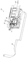
箱体10(筐体11)の内部には、図4〜図9等に示すように、撮像ユニット40等を含む被駆動ユニット60と、この被駆動ユニット60をX−Y平面に平行な面内で自在に移動させるための駆動機構等が配設されている。   Inside the box 10 (housing 11), as shown in FIGS. 4 to 9 and the like, a driven unit 60 including an imaging unit 40 and the like, and a surface parallel to the XY plane A drive mechanism or the like for freely moving within the vehicle is disposed.

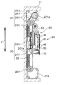
被駆動ユニット60は、詳細は後述するが、撮像光学系(41、42、45等)とその駆動機構(46、47、49、59等)と、撮像素子43aを含む撮像部43、撮像素子駆動基板43b、上記撮像素子駆動基板43bに接続された接続配線部71、光源部44(図7参照)、上記接続配線部71を介して上記撮像素子駆動基板43bと電気的に接続された電気基板62(図8参照)および当該電気基板62に電気的に接続される無線LAN基板72等を含んで構成される撮像ユニット40と、この撮像ユニット40を搭載する移動部材であって後述する第2の移動部材である第2テーブル29Yとを含んで構成される。なお、被駆動ユニット60および撮像ユニット40の詳細構成については、図10〜図13等を用いて後述する。   Although details will be described later, the driven unit 60 includes an imaging optical system (41, 42, 45, etc.), its driving mechanism (46, 47, 49, 59, etc.), an imaging unit 43 including an imaging element 43a, and an imaging element. The drive board 43b, the connection wiring part 71 connected to the imaging element driving board 43b, the light source part 44 (see FIG. 7), and the electricity electrically connected to the imaging element driving board 43b via the connection wiring part 71. An imaging unit 40 including a board 62 (see FIG. 8), a wireless LAN board 72 and the like electrically connected to the electrical board 62, and a moving member on which the imaging unit 40 is mounted. And a second table 29Y which is a second moving member. The detailed configuration of the driven unit 60 and the imaging unit 40 will be described later with reference to FIGS.

箱体10(筐体11)の内部において、上記被駆動ユニット60をX−Y平面に平行な面内で移動させる駆動機構は、第1ガイドレール30X(第1のガイド部、第1のガイド手段)と、第2ガイドレール30Y(第2のガイド部、第2のガイド手段)と、第1テーブル29X(第1の移動部材)と、第2テーブル29Y(第2の移動部材)と、第1の駆動モータ21Xと、第2の駆動モータ21Yと、伝達機構35と、第1の駆動力伝達手段36と、第2の駆動力伝達手段37と、第1位置検出手段(31X、32X)及び第2位置検出手段(31Y、32Y)と、第1位置規制手段33X及び第2位置規制手段33Y等によって構成されている。   Inside the box 10 (housing 11), the drive mechanism for moving the driven unit 60 in a plane parallel to the XY plane is a first guide rail 30X (first guide portion, first guide). Means), a second guide rail 30Y (second guide portion, second guide means), a first table 29X (first moving member), a second table 29Y (second moving member), The first drive motor 21X, the second drive motor 21Y, the transmission mechanism 35, the first drive force transmission means 36, the second drive force transmission means 37, and the first position detection means (31X, 32X) ) And second position detecting means (31Y, 32Y), first position restricting means 33X, second position restricting means 33Y, and the like.

第1ガイドレール30Xは、第1の方向であるX軸方向に沿って延びるように配設され、第1テーブル29XのX軸方向への移動をガイドする第1のガイド部であり第1のガイド手段である。第1ガイドレール30Xは、筐体11の内部において複数設けられている。本実施形態においては、第1ガイドレール30Xを二本設けた例を示している。この場合において、二本の第1ガイドレール30Xのうち一方は側壁11aに隣接する位置において、同側壁11aに沿って所定の範囲に設けられている。また、二本の第1ガイドレール30Xのうち他方は側壁11bに隣接する位置において、同側壁11bに沿って所定の範囲に設けられている。   The first guide rail 30X is disposed so as to extend along the X-axis direction that is the first direction, and is a first guide portion that guides the movement of the first table 29X in the X-axis direction. It is a guide means. A plurality of first guide rails 30 </ b> X are provided inside the housing 11. In the present embodiment, an example in which two first guide rails 30X are provided is shown. In this case, one of the two first guide rails 30X is provided in a predetermined range along the side wall 11a at a position adjacent to the side wall 11a. The other of the two first guide rails 30X is provided in a predetermined range along the side wall 11b at a position adjacent to the side wall 11b.

なお、後述するように、筐体11の内部において、側壁11aに隣接する位置には、同側壁11aに沿うように第1の駆動モータ21Xが設けられている。同様に、筐体11の内部において、側壁11bに隣接する位置には、同側壁11bに沿うように第2の駆動モータ21Yが設けられている。したがって、二本の第1ガイドレール30Xは、上記第1の駆動モータ21X及び第2の駆動モータ21Yが配設されている各側壁11a、11bの隣接位置以外の各側壁11a、11bの隣接位置に設けられている。これにより、第1の駆動モータ21Xと一方の第1ガイドレール30Xとは、それぞれの長軸方向が直線的に、側壁11aに沿うように並べて配設されている。同様に、第2の駆動モータ21Yと他方の第1ガイドレール30Xとは、それぞれの長軸方向が直線的に、側壁11bに沿うように並べて配設されている。   As will be described later, a first drive motor 21X is provided along the side wall 11a at a position adjacent to the side wall 11a in the housing 11. Similarly, a second drive motor 21Y is provided along the side wall 11b at a position adjacent to the side wall 11b in the housing 11. Therefore, the two first guide rails 30X are adjacent positions of the side walls 11a and 11b other than the adjacent positions of the side walls 11a and 11b where the first drive motor 21X and the second drive motor 21Y are disposed. Is provided. Thus, the first drive motor 21X and the first guide rail 30X are arranged side by side so that the major axis directions thereof are linear and along the side wall 11a. Similarly, the second drive motor 21Y and the other first guide rail 30X are arranged side by side so that the major axis directions thereof are linear and along the side wall 11b.

第1テーブル29Xは、第1ガイドレール30Xによってガイドされて、同第1ガイドレール30Xに沿うX軸方向に移動する第1の移動部材である。この第1テーブル29Xは、後述する第1の駆動モータ21Xの回転駆動力により駆動される。そのために、第1テーブル29XのY軸方向における両端部の各下面側には、図9に示すように、第1ガイドレール30Xを摺動可能に保持する第1レール保持部29Xaが設けられている。この第1レール保持部29Xaは、X軸方向に延びるように配設されている。そして、当該第1レール保持部29Xaは、第1ガイドレール30Xの幅方向(軸方向に直交する方向)を抱え込み得る形態の溝形状部を有して形成されている。このような構成により、第1テーブル29Xは、第1ガイドレール30Xにガイドされ、これに沿う方向であるX軸方向にのみ移動するように構成されている。   The first table 29X is a first moving member that is guided by the first guide rail 30X and moves in the X-axis direction along the first guide rail 30X. The first table 29X is driven by a rotational driving force of a first drive motor 21X described later. For this purpose, as shown in FIG. 9, first rail holding portions 29 </ b> Xa that slidably hold the first guide rails 30 </ b> X are provided on the lower surfaces of both ends in the Y-axis direction of the first table 29 </ b> X. Yes. The first rail holding portion 29Xa is disposed so as to extend in the X-axis direction. And the said 1st rail holding | maintenance part 29Xa has a groove-shaped part of the form which can hold the width direction (direction orthogonal to an axial direction) of the 1st guide rail 30X. With such a configuration, the first table 29X is guided by the first guide rail 30X and is configured to move only in the X-axis direction, which is a direction along the first guide rail 30X.

第2ガイドレール30Yは、X軸方向に垂直な第2の方向(Y軸方向)に沿って延びるように配設され、第2テーブル29YのY軸方向への移動をガイドする第2のガイド部であり第2のガイド手段である。第2ガイドレール30Yは、筐体11の内部において、上記第1テーブル29X上に載置される形態で複数設けられている。本実施形態においては、第2ガイドレール30Yを二本設けた例を示している。この場合において、二本の第2ガイドレール30Yは、上記第1テーブル29X上において、X軸方向に所定の間隔を置いて並べて配置されている。   The second guide rail 30Y is disposed so as to extend along a second direction (Y-axis direction) perpendicular to the X-axis direction, and guides the movement of the second table 29Y in the Y-axis direction. And a second guide means. A plurality of second guide rails 30 </ b> Y are provided in the form of being placed on the first table 29 </ b> X inside the housing 11. In the present embodiment, an example in which two second guide rails 30Y are provided is shown. In this case, the two second guide rails 30Y are arranged side by side at a predetermined interval in the X-axis direction on the first table 29X.

第2テーブル29Yは、第2ガイドレール30Yによってガイドされて、同第2ガイドレール30Yに沿ってY軸方向に移動する第2の移動部材である。また、第2テーブル29Yは、第1テーブル29Xと共にX軸方向にも移動するように構成されている。そのために、第2テーブル29Yの下面側には、図8に示すように、二本の第2ガイドレール30Yをそれぞれ摺動可能に保持する第2レール保持部29Yaが設けられている。この第2レール保持部29Yaは、Y軸方向に延びるように配設されている。そして、当該第2レール保持部29Yaは、第2ガイドレール30Yの幅方向(軸方向に直交する方向)を抱え込み得る形態の溝形状部を有して形成されている。このような構成により、第2テーブル29Yは、第2ガイドレール30Yによってガイドされて、同第2ガイドレール30Yに沿ってY軸方向に移動すると共に、第1テーブル29Xが第1ガイドレール30Xによってガイドされて、同第1ガイドレール30Xに沿ってX軸方向に移動する際には、当該第1テーブル29Xと共に同方向(X軸方向)に移動する。   The second table 29Y is a second moving member that is guided by the second guide rail 30Y and moves in the Y-axis direction along the second guide rail 30Y. Further, the second table 29Y is configured to move in the X axis direction together with the first table 29X. For this purpose, as shown in FIG. 8, a second rail holding portion 29Ya is provided on the lower surface side of the second table 29Y to hold the two second guide rails 30Y slidably. The second rail holding portion 29Ya is disposed so as to extend in the Y-axis direction. And the said 2nd rail holding | maintenance part 29Ya has a groove-shaped part of the form which can hold the width direction (direction orthogonal to an axial direction) of the 2nd guide rail 30Y. With such a configuration, the second table 29Y is guided by the second guide rail 30Y and moves in the Y-axis direction along the second guide rail 30Y, and the first table 29X is moved by the first guide rail 30X. When guided and moved in the X-axis direction along the first guide rail 30X, it moves in the same direction (X-axis direction) together with the first table 29X.

そして、上述したように、上記第2テーブル29Yには、撮像部43を含む撮像ユニット40等が搭載されている。これにより、上記第2テーブル29Yは、被駆動ユニット60の一部として機能する。   As described above, the imaging unit 40 including the imaging unit 43 is mounted on the second table 29Y. Thus, the second table 29Y functions as a part of the driven unit 60.

第1の駆動モータ21Xは、第1テーブル29XをX軸方向に移動させ駆動するための回転力を出力する第1の回転軸21Xa(図5参照)を有する駆動モータである。第1の駆動モータ21Xは、上述したように、箱体10(筐体11)の第1の側壁11aに隣接して設けられている。この場合において、第1の回転軸21Xaは、第1ガイドレール30Xと平行に配置されている。上記第1の駆動モータ21Xの上記第1の回転軸21Xaから出力される回転駆動力は、第1の駆動力伝達手段36を介して第1テーブル29Xへと伝達されて、当該第1テーブル29XをX軸方向へと移動させるように構成されている。   The first drive motor 21X is a drive motor having a first rotation shaft 21Xa (see FIG. 5) that outputs a rotational force for driving the first table 29X in the X-axis direction. As described above, the first drive motor 21X is provided adjacent to the first side wall 11a of the box 10 (housing 11). In this case, the first rotating shaft 21Xa is disposed in parallel with the first guide rail 30X. The rotational driving force output from the first rotating shaft 21Xa of the first driving motor 21X is transmitted to the first table 29X via the first driving force transmitting means 36, and the first table 29X. Are moved in the X-axis direction.

第1の駆動力伝達手段36は、第1の駆動モータ21Xからの回転出力を第1テーブル29X(第1の移動部材)に伝達する駆動力伝達機構である。第1の駆動力伝達手段36は、第1減速手段22Xと、送りねじ23Xと、送りナット24Xとによって構成されている。   The first driving force transmission means 36 is a driving force transmission mechanism that transmits the rotational output from the first driving motor 21X to the first table 29X (first moving member). The first driving force transmission means 36 is constituted by a first speed reduction means 22X, a feed screw 23X, and a feed nut 24X.

第1減速手段22Xは、第1の駆動モータ21Xの第1の回転軸21Xaからの回転出力を受けて減速するギアー列等を内部に有する構成ユニットである。第1減速手段22Xの構成自体は、従来一般に周知の動力減速手段と同様のものが適用されているものとして、その詳細説明は省略する。   The first decelerating means 22X is a structural unit having therein a gear train or the like that decelerates by receiving the rotational output from the first rotating shaft 21Xa of the first drive motor 21X. The configuration itself of the first speed reduction means 22X is the same as that of a conventionally known power reduction means, and detailed description thereof is omitted.

送りねじ23Xは、上記第1減速手段22Xからの回転出力を受けて回転する棒状部材である。この送りねじ23Xの基端は上記第1減速手段22Xに連結されている。また、当該送りねじ23Xの他端は、筐体11の内壁面の固定部に対し回転を許容しながら回動自在に軸支されている。   The feed screw 23X is a rod-shaped member that rotates in response to the rotational output from the first reduction means 22X. The base end of the feed screw 23X is connected to the first reduction means 22X. The other end of the feed screw 23X is pivotally supported while allowing rotation with respect to a fixed portion of the inner wall surface of the housing 11.

送りナット24Xは、上記送りねじ23Xに螺合するナット部を内部に備え、上記第1テーブル29Xに固定される構成部である。この構成により、第1の駆動モータ21Xの回転出力を受けて上記送りねじ23Xが回転すると、当該送りねじ23Xに螺合するナット部の作用により、送りナット24XはX軸に沿う方向に移動する。これと同時に第1テーブル29Xも同方向に移動する。この場合において、第1の駆動モータ21Xの回転方向を制御することにより、送りナット24Xの回転方向を制御して、これにより第1テーブル29XのX軸に沿う方向における進退方向を制御することができる。   The feed nut 24X is a component that includes a nut portion that is screwed into the feed screw 23X and is fixed to the first table 29X. With this configuration, when the feed screw 23X rotates upon receiving the rotation output of the first drive motor 21X, the feed nut 24X moves in the direction along the X axis by the action of the nut portion screwed into the feed screw 23X. . At the same time, the first table 29X moves in the same direction. In this case, it is possible to control the rotation direction of the feed nut 24X by controlling the rotation direction of the first drive motor 21X, and thereby to control the advance / retreat direction in the direction along the X axis of the first table 29X. it can.

つまり、第1テーブル29Xは、第1の駆動モータ21X及び送りねじ23X、送りナット24X等を用いた送りねじ駆動方式により、第1の駆動モータ21Xの第1の回転軸21Xaに平行な方向(X軸方向)に移動する。   That is, the first table 29X is parallel to the first rotation shaft 21Xa of the first drive motor 21X by a feed screw drive system using the first drive motor 21X, the feed screw 23X, the feed nut 24X, and the like ( Move in the X-axis direction).

第2の駆動モータ21Yは、第2テーブル29YをY軸方向に移動させ駆動するための回転力を出力する第2の回転軸22Ya(図7参照)を有する駆動モータである。第2の駆動モータ21Yは、箱体10(筐体11)の第1の側壁11aと対向する第2の側壁11bに隣接して設けられている。この場合において、第2の回転軸22Yaが第1ガイドレール30X及び第1の回転軸21Xaと平行となるように配置されている。   The second drive motor 21Y is a drive motor having a second rotation shaft 22Ya (see FIG. 7) that outputs a rotational force for driving the second table 29Y by moving it in the Y-axis direction. The second drive motor 21Y is provided adjacent to the second side wall 11b facing the first side wall 11a of the box 10 (housing 11). In this case, the second rotation shaft 22Ya is disposed so as to be parallel to the first guide rail 30X and the first rotation shaft 21Xa.

上記第2の駆動モータ21Yの上記第2の回転軸21Yaから出力される回転駆動力は、第2の駆動力伝達手段37及び伝達機構35を介して撮像部43を含む撮像ユニット40等を搭載する第2テーブル29Yへと伝達されて、これ(第2テーブル29Y)をY軸方向へと移動させるように構成されている。   The rotational driving force output from the second rotating shaft 21Ya of the second driving motor 21Y is mounted with the imaging unit 40 including the imaging unit 43 via the second driving force transmission means 37 and the transmission mechanism 35. Is transmitted to the second table 29Y, and this (second table 29Y) is moved in the Y-axis direction.

換言すると、第2テーブル29Yは、第2の駆動モータ21Yからの回転力を伝達する第2の駆動力伝達手段37に含まれる伝達機構35を介してY軸方向に移動する。   In other words, the second table 29Y moves in the Y-axis direction via the transmission mechanism 35 included in the second driving force transmission means 37 that transmits the rotational force from the second driving motor 21Y.

第2の駆動力伝達手段37は、第2の駆動モータ21Yからの回転出力を撮像部43が搭載される第2テーブル29Y(第2の移動部材)に伝達する駆動力伝達機構である。第2の駆動力伝達手段37は、第2減速手段22Yと、駆動ベルト23Yと、複数のプーリ24Y、25Yと、伝達機構35を含んで構成されている。   The second driving force transmission means 37 is a driving force transmission mechanism that transmits the rotation output from the second driving motor 21Y to the second table 29Y (second moving member) on which the imaging unit 43 is mounted. The second driving force transmission means 37 includes a second speed reduction means 22Y, a driving belt 23Y, a plurality of pulleys 24Y and 25Y, and a transmission mechanism 35.

第2減速手段22Yは、第2の駆動モータ21Yの第2の回転軸21Yaからの回転出力を受けて減速するギアー列等を内部に有する構成ユニットであり、上記第1減速手段22Xと略同様の構成ユニットである。したがって、第2減速手段22Yにおいても、その構成自体は、従来一般に周知の動力減速手段と同様のものが適用されているものとして、その詳細説明は省略する。   The second speed reduction means 22Y is a structural unit having a gear train or the like that receives a rotational output from the second rotation shaft 21Ya of the second drive motor 21Y and decelerates therein, and is substantially the same as the first speed reduction means 22X. It is a component unit. Therefore, the second reduction means 22Y also has the same configuration as that of a conventionally known power reduction means, and a detailed description thereof will be omitted.

駆動ベルト23Y及び複数のプーリ24Y、25Yは、上記第2減速手段22Yからの回転出力を受けて、これをY軸方向の移動出力に変換する構成部材である。複数のプーリ24Y、25Yのうちプーリ24Yは第2減速手段22Yからの回転出力を出力する軸部材に同軸上に固設されている。各プーリ24Y、25Yには、駆動ベルト23Yが張架されていて、第2の駆動モータ21Yの回転出力を受けて移動する駆動ベルト23Yの移動をガイドすると共に、駆動ベルト23Yの位置決め等を行っている。駆動モータの回転出力を駆動ベルトによって変換する機構は、従来周知であるので、これ以上の詳細説明は省略する。   The drive belt 23Y and the plurality of pulleys 24Y and 25Y are components that receive the rotational output from the second reduction means 22Y and convert it into a movement output in the Y-axis direction. Of the plurality of pulleys 24Y and 25Y, the pulley 24Y is coaxially fixed to the shaft member that outputs the rotation output from the second reduction means 22Y. A drive belt 23Y is stretched around each pulley 24Y, 25Y, guides the movement of the drive belt 23Y that moves by receiving the rotational output of the second drive motor 21Y, and positions the drive belt 23Y. ing. Since the mechanism for converting the rotational output of the drive motor by the drive belt is well known in the art, further detailed description is omitted.

そして、駆動ベルト23Yの所定の部位には、上記伝達機構35の一部が固定配置されている。この構成により、第2の駆動モータ21Yの回転出力を受けて駆動ベルト23YがY軸に沿う方向に移動すると、上記伝達機構35も同方向に移動するように構成されている。この場合において、第2の駆動モータ21Yの回転方向を制御することにより、駆動ベルト23Yの送り方向及び伝達機構35のY軸に沿う方向における進退方向を制御することができる。   A part of the transmission mechanism 35 is fixedly disposed at a predetermined portion of the drive belt 23Y. With this configuration, when the drive belt 23Y moves in the direction along the Y axis in response to the rotational output of the second drive motor 21Y, the transmission mechanism 35 also moves in the same direction. In this case, by controlling the rotation direction of the second drive motor 21Y, the feed direction of the drive belt 23Y and the advance / retreat direction in the direction along the Y axis of the transmission mechanism 35 can be controlled.

つまり、伝達機構35は、第2の駆動モータ21Y及び駆動ベルト23Y等を用いたベルト駆動方式により、第2の駆動モータ21Yの第2の回転軸21Yaに直交する方向(Y軸方向)に移動する。   That is, the transmission mechanism 35 moves in a direction (Y-axis direction) orthogonal to the second rotation shaft 21Ya of the second drive motor 21Y by a belt drive system using the second drive motor 21Y and the drive belt 23Y. To do.

上記伝達機構35は、第3ガイドレール28Y(第3のガイド部、第3のガイド手段)と、ベルト保持部26Y及び第3テーブル27Yからなる第3の移動部材と、連結部材39とによって構成される。   The transmission mechanism 35 includes a third guide rail 28Y (third guide portion, third guide means), a third moving member including a belt holding portion 26Y and a third table 27Y, and a connecting member 39. Is done.

第3ガイドレール28Yは、第2ガイドレール30Yと平行に配置され、第3の移動部材(26Y、27Y)のY軸方向への移動をガイドする第3のガイド部であり第3のガイド手段である。   The third guide rail 28Y is arranged in parallel with the second guide rail 30Y, and is a third guide portion that guides the movement of the third moving member (26Y, 27Y) in the Y-axis direction, and is a third guide means. It is.

上記第3の移動部材は、第2の駆動モータ21Yからの回転力を受けて、上記第3ガイドレール28Yに沿ってY軸方向に移動する移動部材である。上記第3の移動部材は、ベルト保持部26Y及び第3テーブル27Yとからなる。ベルト保持部26Yは、上記駆動ベルト23Yの所定の部位(図4において符号26Yaで示す固定部位)に固定される構成部材である。第3テーブル27Yは、第3ガイドレール28Yによってガイドされて、同第3ガイドレール28Yに沿うY軸方向に移動する移動部材である。そのために、上記第3テーブル27Yの下面側には、図8に示すように、第3ガイドレール28Yを摺動可能に保持する第3レール保持部27Yaが設けられている。この第3レール保持部27Yaは、Y軸方向に延びるように配設されている。そして、当該第3レール保持部27Yaは、第3ガイドレール28Yの幅方向(軸方向に直交する方向)を抱え込み得る形態の溝形状部を有して形成されている。このような構成により、第3テーブル27Yは、第3ガイドレール28Yによってガイドされて、同第3ガイドレール28Yに沿ってY軸方向に移動する。   The third moving member is a moving member that receives the rotational force from the second drive motor 21Y and moves in the Y-axis direction along the third guide rail 28Y. The third moving member includes a belt holding portion 26Y and a third table 27Y. The belt holding portion 26Y is a structural member that is fixed to a predetermined portion (a fixed portion indicated by reference numeral 26Ya in FIG. 4) of the drive belt 23Y. The third table 27Y is a moving member that is guided by the third guide rail 28Y and moves in the Y-axis direction along the third guide rail 28Y. For this purpose, as shown in FIG. 8, a third rail holding portion 27Ya is provided on the lower surface side of the third table 27Y to hold the third guide rail 28Y in a slidable manner. The third rail holding portion 27Ya is disposed so as to extend in the Y-axis direction. And the said 3rd rail holding | maintenance part 27Ya has a groove-shaped part of the form which can hold the width direction (direction orthogonal to an axial direction) of the 3rd guide rail 28Y. With such a configuration, the third table 27Y is guided by the third guide rail 28Y and moves in the Y-axis direction along the third guide rail 28Y.

上記第3テーブル27Yには、上記ベルト保持部26Yが固定されている。上述したように、ベルト保持部26Yは、駆動ベルト23Yの固定部位26Yaにおいて固定されている。したがって、この構成により、駆動ベルト23Yが第2の駆動モータ21Yの回転出力を受けてY軸に沿う方向に移動すると、上記第3テーブル27Yもまた同方向に移動するように構成されている。   The belt holding portion 26Y is fixed to the third table 27Y. As described above, the belt holding portion 26Y is fixed at the fixing portion 26Ya of the drive belt 23Y. Therefore, with this configuration, when the drive belt 23Y receives the rotational output of the second drive motor 21Y and moves in the direction along the Y axis, the third table 27Y also moves in the same direction.

連結部材39は、上記第3の移動部材の第3テーブル27Yと、上記撮像部43を含む撮像ユニット40等を搭載する第2テーブル29Yと、を連結する部材である。連結部材39の一端は第3テーブル27Yに固定され、同連結部材39の他端には、第2テーブル29YがX軸方向へ移動可能に保持されている(図6等参照)。   The connecting member 39 is a member that connects the third table 27Y of the third moving member and the second table 29Y on which the imaging unit 40 including the imaging unit 43 is mounted. One end of the connecting member 39 is fixed to the third table 27Y, and the second table 29Y is held at the other end of the connecting member 39 so as to be movable in the X-axis direction (see FIG. 6 and the like).

このように、上記第3の移動部材(の第3テーブル27Y)と上記第2テーブル29Yとが連結部材39によって連結されているので、第2の駆動モータ21Yからの出力に基づいて第3の移動部材(26Y、27Y)が第3ガイドレール28Yに沿って移動する際、上記第2テーブル29Yは、上記第3の移動部材(26Y、27Y)の第3ガイドレール28Yに沿うY軸方向の移動に連動して、第2ガイドレール30Yに沿ってY軸方向に移動する。   Thus, since the third moving member (the third table 27Y) and the second table 29Y are connected by the connecting member 39, the third moving member 21Y is based on the output from the second drive motor 21Y. When the moving member (26Y, 27Y) moves along the third guide rail 28Y, the second table 29Y moves in the Y-axis direction along the third guide rail 28Y of the third moving member (26Y, 27Y). In conjunction with the movement, the Y-axis direction moves along the second guide rail 30Y.

第1位置検出手段は、第1テーブル29XのX軸方向における移動範囲の両端位置を検出し、当該第1テーブル29XのX軸方向における移動範囲を制御するために設けられる構成部である。この第1位置検出手段は、一対の第1位置検出センサ31Xと、第1遮光羽根32Xとによって構成されている。一対の第1位置検出センサ31Xは、第2の側壁11bの内壁面にX軸方向に所定の間隔をおいて配置されている。本実施形態においては、上記一対の第1位置検出センサ31Xとして、例えばいわゆる透過型フォトインタラプタ等の検出素子を適用した例を示している。第1遮光羽根32Xは、第1テーブル29X上に配設されている。この場合において、上記第1遮光羽根32Xは、第1テーブル29XがX軸方向に移動したときに上記一対の第1位置検出センサ31Xのそれぞれに対応する位置に配設されている(図4等参照)。   The first position detection means is a component provided to detect both end positions of the movement range of the first table 29X in the X-axis direction and to control the movement range of the first table 29X in the X-axis direction. The first position detection means is constituted by a pair of first position detection sensors 31X and a first light shielding blade 32X. The pair of first position detection sensors 31X are disposed on the inner wall surface of the second side wall 11b at a predetermined interval in the X-axis direction. In the present embodiment, an example is shown in which a detection element such as a so-called transmissive photo interrupter is applied as the pair of first position detection sensors 31X. The first light shielding blade 32X is disposed on the first table 29X. In this case, the first light shielding blade 32X is disposed at a position corresponding to each of the pair of first position detection sensors 31X when the first table 29X moves in the X-axis direction (FIG. 4 and the like). reference).

第1位置規制手段33Xは、第1テーブル29XのX軸方向の移動を所定の範囲内となるように規制するために設けられる部材である。第1位置規制手段33Xは、第1テーブル29XがX軸方向に移動したときに当接する位置に設けられる。つまり、第1テーブル29XがX軸方向において一方向の移動時に当接する位置と、他方向の移動時に当接する位置との二箇所に設けられる。これにより、第1テーブル29XのX軸方向の移動範囲が規制される。本実施形態においては、第1位置規制手段33Xの具体的な形態として、例えば筐体11の底面から当該筐体11の内方(即ち上方)に向けて突設される突起状部材を設けた例を示している(図4等参照)。   The first position restricting means 33X is a member provided for restricting movement of the first table 29X in the X-axis direction to be within a predetermined range. The first position regulating means 33X is provided at a position where the first table 29X contacts when the first table 29X moves in the X-axis direction. That is, the first table 29X is provided at two locations, a position where the first table 29X contacts when moving in one direction in the X-axis direction and a position where the first table 29X contacts when moving in the other direction. Thereby, the movement range in the X-axis direction of the first table 29X is restricted. In the present embodiment, as a specific form of the first position restricting means 33X, for example, a protruding member that protrudes from the bottom surface of the housing 11 toward the inside (that is, upward) of the housing 11 is provided. An example is shown (see FIG. 4 etc.).

第2位置検出手段は、第3テーブル27YのY軸方向における移動範囲の両端位置を検出し、当該第3テーブル27YのY軸方向における移動範囲を制御するために設けられる構成部である。この第2位置検出手段は、一対の第2位置検出センサ31Yと、第2遮光羽根32Yとによって構成されている。一対の第2位置検出センサ31Yは、筐体11の底面において、第3ガイドレール28Yの近傍位置に当該第3ガイドレール28Yに沿うY軸方向に所定の間隔をおいて配置されている。本実施形態においては、上記一対の第2位置検出センサ31Yとして、例えばいわゆる透過型フォトインタラプタ等の検出素子を適用した例を示している。第2遮光羽根32Yは、第3テーブル27Y上に配設されている。この場合において、上記第2遮光羽根32Yは、第3テーブル27YがY軸方向に移動したときに上記一対の第2位置検出センサ31Yのそれぞれに対応する位置に配設されている(図4等参照)。   The second position detection means is a component provided to detect both end positions of the movement range of the third table 27Y in the Y-axis direction and to control the movement range of the third table 27Y in the Y-axis direction. This second position detection means is constituted by a pair of second position detection sensors 31Y and a second light shielding blade 32Y. The pair of second position detection sensors 31Y are arranged on the bottom surface of the housing 11 at a predetermined interval in the Y-axis direction along the third guide rail 28Y at a position near the third guide rail 28Y. In the present embodiment, an example is shown in which a detection element such as a so-called transmissive photo interrupter is applied as the pair of second position detection sensors 31Y. The second light shielding blade 32Y is disposed on the third table 27Y. In this case, the second light shielding blade 32Y is disposed at a position corresponding to each of the pair of second position detection sensors 31Y when the third table 27Y moves in the Y-axis direction (FIG. 4 and the like). reference).

第2位置規制手段33Yは、第3テーブル27YのY軸方向の移動を所定の範囲内となるように規制するために設けられる部材である。第2位置規制手段33Yは、第3テーブル27YがY軸方向に移動したときに当接する位置に設けられる。つまり、第3テーブル27YがY軸方向において一方向の移動時に当接する位置と、他方向の移動時に当接する位置との二箇所に設けられる。これにより、第3テーブル27YのY軸方向の移動範囲が規制される。本実施形態においては、第2位置規制手段33Yの具体的な形態として、例えば筐体11の底面から当該筐体11の内方(即ち上方)に向けて突設される突起状部材を設けた例を示している(図4等参照)。   The second position restricting means 33Y is a member provided for restricting the movement of the third table 27Y in the Y-axis direction to be within a predetermined range. The second position restricting means 33Y is provided at a position where the third table 27Y contacts when the third table 27Y moves in the Y-axis direction. That is, the third table 27Y is provided at two locations, a position where the third table 27Y contacts when moving in one direction and a position where the third table 27Y contacts when moving in the other direction. Thereby, the movement range of the 3rd table 27Y of the Y-axis direction is controlled. In the present embodiment, as a specific form of the second position regulating means 33Y, for example, a protruding member that protrudes from the bottom surface of the housing 11 toward the inside (that is, the upper side) of the housing 11 is provided. An example is shown (see FIG. 4 etc.).

次に、上記被駆動ユニット60の詳細構成について、図10〜図15等を用いて以下に説明する。   Next, the detailed configuration of the driven unit 60 will be described below with reference to FIGS.

被駆動ユニット60は、上述したように、撮像ユニット40と、この撮像ユニット40を搭載する第2の移動部材である第2テーブル29Yとを含んで構成される。   As described above, the driven unit 60 includes the imaging unit 40 and the second table 29Y that is a second moving member on which the imaging unit 40 is mounted.

撮像ユニット40は、プリズム41(光学要素)と、撮像部43を含む移動光学系(42、45)と、その駆動機構である駆動手段(46〜52、59)と、光源部44と、撮像素子43aの駆動制御系(撮像素子駆動基板43b)と、撮像素子43aから出力される撮像信号の画像処理系(電気基板62、接続配線部71)と、外部機器との信号送受信を行う無線送受信系(無線LAN基板72、信号配線部73)等を有して構成されている。   The imaging unit 40 includes a prism 41 (optical element), a moving optical system (42, 45) including an imaging unit 43, driving means (46 to 52, 59) that are driving mechanisms thereof, a light source unit 44, and imaging. Wireless transmission / reception that performs signal transmission / reception between the drive control system of the element 43a (imaging element drive board 43b), the image processing system of the imaging signal output from the imaging element 43a (electrical board 62, connection wiring unit 71), and an external device. System (wireless LAN board 72, signal wiring section 73) and the like.

上記プリズム41は、培養器13内の試料を透過してきた光を反射する反射面41aを有する光学要素である。つまり、本実施形態におけるプリズム41は、箱体10の蓋体12上の所定の部位(光透過部12a)に載置した培養器13内の試料を透過してきた光を受けて、その光路を角度90度折り曲げて、所定の方向、即ち撮像素子43aの受光面(不図示)に向けて反射させる機能を有する。このプリズム41は、光を反射するのみの機能を有し、光の屈折を伴わない部材、即ちレンズ効果を有していない部材が適用される。このプリズム41は、第2テーブル29Y上に固設されている。   The prism 41 is an optical element having a reflecting surface 41 a that reflects light transmitted through the sample in the incubator 13. That is, the prism 41 in the present embodiment receives light transmitted through the sample in the incubator 13 placed on a predetermined portion (light transmission portion 12a) on the lid body 12 of the box body 10, and changes its optical path. It has a function of being bent at an angle of 90 degrees and reflecting toward a predetermined direction, that is, a light receiving surface (not shown) of the image sensor 43a. The prism 41 has a function of only reflecting light, and a member that does not refraction light, that is, a member that does not have a lens effect is applied. The prism 41 is fixed on the second table 29Y.

本実施形態においては、上記反射面を有する光学要素の形態として、プリズムを使用する例を挙げているが、この形態以外にも、例えば反射ミラーを適用した構成例を考えることも可能である。   In the present embodiment, an example of using a prism is given as a form of the optical element having the reflection surface. However, besides this form, for example, a configuration example in which a reflection mirror is applied can be considered.

移動光学系(42、45、43)は、プリズム41(光学要素)からの光を撮像素子43aの受光面へと結像させるように光軸Oに沿う方向に移動可能に構成された構成ユニットである。なお、本実施形態において、移動光学系の光軸Oは、X軸に沿う方向となるように配置されている。したがって、移動光学系は、X軸方向に進退移動し得るように構成されている。   The moving optical system (42, 45, 43) is configured to be movable in the direction along the optical axis O so that the light from the prism 41 (optical element) forms an image on the light receiving surface of the image sensor 43a. It is. In the present embodiment, the optical axis O of the moving optical system is arranged so as to be along the X axis. Therefore, the moving optical system is configured to move forward and backward in the X-axis direction.

上記移動光学系は、複数の光学レンズ42と、これら複数の光学レンズ42を保持する複数のレンズ保持部材45とを一体に構成した光学部と、撮像素子43a等を含む撮像部43と、を一体に構成した構成ユニットである。   The moving optical system includes an optical unit integrally configured with a plurality of optical lenses 42 and a plurality of lens holding members 45 that hold the plurality of optical lenses 42, and an imaging unit 43 including an imaging element 43a and the like. This is a unit configured integrally.

なお、上記プリズム41と、上記複数の光学レンズ42及び複数のレンズ保持部材45とによって構成される構成部を撮像光学系というものとする。そして、上記プリズム41(光学要素)及び移動光学系によって構成される上記撮像光学系は、全体としてテレセントリック光学系を形成している。   A component constituted by the prism 41, the plurality of optical lenses 42, and the plurality of lens holding members 45 is referred to as an imaging optical system. The imaging optical system constituted by the prism 41 (optical element) and the moving optical system forms a telecentric optical system as a whole.

上記移動光学系(42、45、43)は、上記第2テーブル29Y上において、X軸方向に移動可能に配設されている。そのために、上記第2テーブル29Y上には、上記移動光学系のX軸方向への移動をガイドするガイド手段であるフォーカスレール51が複数(本実施形態では二本)設けられている。このフォーカスレール51は、上記第2テーブル29Y上においてX軸方向に沿って延びるように配設されている。   The moving optical system (42, 45, 43) is disposed on the second table 29Y so as to be movable in the X-axis direction. For this purpose, a plurality (two in this embodiment) of focus rails 51 as guide means for guiding the movement of the moving optical system in the X-axis direction are provided on the second table 29Y. The focus rail 51 is disposed on the second table 29Y so as to extend along the X-axis direction.

これに対応させて、上記移動光学系は、上記フォーカスレール51を摺動可能に保持するフォーカスレール保持部59aを有する移動光学系保持部59によって保持されている(図9、図14参照)。   Correspondingly, the moving optical system is held by a moving optical system holding part 59 having a focus rail holding part 59a that holds the focus rail 51 slidably (see FIGS. 9 and 14).

この移動光学系保持部59は、当該移動光学系の駆動機構(詳細後述)の一部を構成する構成部材である。この移動光学系保持部59の下面側には、上記フォーカスレール保持部59aが固定配置されている。そして、上記フォーカスレール保持部59aは、フォーカスレール51の幅方向(軸方向に直交する方向)を抱え込み得る形態の溝形状部を有して形成されている。上記フォーカスレール保持部59aは、上記二本のフォーカスレール51に対応させて二個設けられている。このような構成により、上記移動光学系は、上記フォーカスレール51によってガイドされて、同フォーカスレール51に沿うX軸方向にのみ移動する。その場合において、上記移動光学系は、後述するフォーカス駆動モータ46の回転駆動力により駆動される。   The moving optical system holding unit 59 is a constituent member that constitutes a part of a driving mechanism (details will be described later) of the moving optical system. On the lower surface side of the moving optical system holding part 59, the focus rail holding part 59a is fixedly arranged. The focus rail holding portion 59a is formed to have a groove-shaped portion that can hold the width direction of the focus rail 51 (the direction orthogonal to the axial direction). Two focus rail holding portions 59 a are provided corresponding to the two focus rails 51. With such a configuration, the moving optical system is guided by the focus rail 51 and moves only in the X-axis direction along the focus rail 51. In that case, the moving optical system is driven by a rotational driving force of a focus driving motor 46 described later.

上記移動光学系の駆動機構は、移動光学系(42、45)全体を、当該移動光学系の光軸Oに沿って移動させるための駆動手段である。   The driving mechanism of the moving optical system is a driving means for moving the entire moving optical system (42, 45) along the optical axis O of the moving optical system.

上記移動光学系の駆動機構は、フォーカス駆動モータ46と、フォーカス減速機構47と、フォーカス回転出力軸48と、フォーカスナット49と、付勢ばね51と、移動光学系保持部59等によって構成される。   The drive mechanism for the moving optical system includes a focus drive motor 46, a focus reduction mechanism 47, a focus rotation output shaft 48, a focus nut 49, a biasing spring 51, a moving optical system holding portion 59, and the like. .

フォーカス駆動モータ46は、上記移動光学系をX軸方向に進退移動させるための駆動源である。このフォーカス駆動モータ46は、支持部材である第2テーブル29Y上に固設されている。その場合において、当該フォーカス駆動モータ46の回転軸(不図示)は、X軸に沿う方向に配置されている。   The focus drive motor 46 is a drive source for moving the moving optical system forward and backward in the X-axis direction. The focus drive motor 46 is fixed on the second table 29Y as a support member. In that case, the rotation axis (not shown) of the focus drive motor 46 is arranged in the direction along the X axis.

フォーカス減速機構47は、フォーカス駆動モータ46の回転軸からの回転出力を受けて減速するギアー列等を内部に有する構成ユニットである。フォーカス減速機構47の構成自体は、従来一般に周知の動力減速手段と同様のものが適用されているものとして、その詳細説明は省略する。なお、このフォーカス減速機構47も、支持部材である第2テーブル29Y上に固設されている。   The focus decelerating mechanism 47 is a constituent unit having a gear train or the like that decelerates in response to a rotation output from the rotation shaft of the focus drive motor 46. The configuration itself of the focus reduction mechanism 47 is the same as that of conventionally known power reduction means, and detailed description thereof is omitted. The focus reduction mechanism 47 is also fixed on the second table 29Y as a support member.

フォーカス回転出力軸48は、上記フォーカス減速機構47からの回転力を出力する回転軸であって、例えば送りねじ形状に形成されている。このフォーカス回転出力軸48は、上記フォーカス減速機構47と後述のフォーカスナット49との間を連結し、フォーカス駆動モータ46の回転駆動力をフォーカスナット49へと伝達する役目をする。   The focus rotation output shaft 48 is a rotation shaft that outputs the rotational force from the focus reduction mechanism 47, and is formed in a feed screw shape, for example. The focus rotation output shaft 48 connects between the focus reduction mechanism 47 and a focus nut 49 described later, and serves to transmit the rotational drive force of the focus drive motor 46 to the focus nut 49.

フォーカスナット49は、上記フォーカス駆動モータ46の回転出力によって、X軸方向に進退移動する被駆動部材である。このフォーカスナット49は、上記送りねじ形状のフォーカス回転出力軸48に螺合するナット部を内部に備え、上記第2テーブル29Y上に固設されている構成部である。このフォーカスナット49は、支持部材である第2テーブル29Yに対してX軸方向に移動可能に設けられている。   The focus nut 49 is a driven member that moves forward and backward in the X-axis direction by the rotation output of the focus drive motor 46. The focus nut 49 includes a nut portion that is screwed to the feed screw-shaped focus rotation output shaft 48 and is fixed on the second table 29Y. The focus nut 49 is provided so as to be movable in the X-axis direction with respect to the second table 29Y as a support member.

この構成により、フォーカス駆動モータ46の回転出力を受けて、上記フォーカス回転出力軸48(送りねじ)が回転すると、当該フォーカス回転出力軸48に螺合するナット部の作用により、上記フォーカスナット49は、X軸に沿う方向に移動する。ここで、フォーカスナット49(被駆動部材)は、上記移動光学系保持部59(保持部)と一体的に結合されている。これにより、上記フォーカスナット49がX軸に沿う方向に移動すると、同時に上記移動光学系保持部59(保持部)も同方向に移動する。したがって、上記移動光学系保持部59(保持部)によって一体に保持される移動光学系もまた同方向に移動する。この場合において、フォーカス駆動モータ46の回転方向を制御することにより、フォーカスナット49のナット部の回転方向を制御して、これにより移動光学系のX軸に沿う方向における進退方向を制御することができる。   With this structure, when the rotation output of the focus drive motor 46 is received and the focus rotation output shaft 48 (feed screw) rotates, the focus nut 49 is moved by the action of the nut portion screwed to the focus rotation output shaft 48. , Move in the direction along the X axis. Here, the focus nut 49 (driven member) is integrally coupled to the moving optical system holding part 59 (holding part). Accordingly, when the focus nut 49 moves in the direction along the X axis, the moving optical system holding unit 59 (holding unit) simultaneously moves in the same direction. Therefore, the moving optical system integrally held by the moving optical system holding unit 59 (holding unit) also moves in the same direction. In this case, by controlling the rotation direction of the focus drive motor 46, the rotation direction of the nut portion of the focus nut 49 can be controlled, thereby controlling the advance / retreat direction in the direction along the X axis of the moving optical system. it can.

このような構成により、上記駆動手段である駆動機構によって、移動光学系をX軸方向、即ち光軸Oに沿う方向に適宜進退移動させることで焦点位置を調整すると共に、移動光学系を光軸Oに沿う方(X軸方向)に移動させる際には、当該移動光学系の画角が一定となるように構成されている。そのために、プリズム41及び移動光学系からなる本実施形態の試料観察装置1における撮像光学系は、全体としてテレセントリック光学系が採用されている。   With such a configuration, the driving mechanism as the driving means adjusts the focal position by appropriately moving the moving optical system in the X axis direction, that is, the direction along the optical axis O, and adjusts the moving optical system to the optical axis. When moving in the direction along the O (X-axis direction), the angle of view of the moving optical system is configured to be constant. For this purpose, a telecentric optical system is employed as a whole for the imaging optical system in the sample observation apparatus 1 of the present embodiment including the prism 41 and the moving optical system.

付勢ばね51は、第2テーブル29Y(固定部)に対してフォーカスナット49を一方向に付勢する付勢部材である。この付勢ばね51は、一端がフォーカスナット49に、他端が第2テーブル29Yの固定部に、それぞれ固定されている。そのために、フォーカスナット49には、付勢ばね51の一端を固定するばね係止軸50が設けられている。また、第2テーブル29Y上の固定部には、付勢ばね51の他端を固定する支軸52が植設されている。本実施形態における付勢ばね51としては、例えば緊縮性のコイルばね等を適用した例を示している。   The biasing spring 51 is a biasing member that biases the focus nut 49 in one direction with respect to the second table 29Y (fixed portion). One end of the biasing spring 51 is fixed to the focus nut 49, and the other end is fixed to the fixing portion of the second table 29Y. For this purpose, the focus nut 49 is provided with a spring locking shaft 50 that fixes one end of the biasing spring 51. A support shaft 52 that fixes the other end of the urging spring 51 is implanted in the fixed portion on the second table 29Y. As the biasing spring 51 in the present embodiment, an example in which, for example, a coiled coil spring or the like is applied is shown.

光源部44は、第2テーブル29Y上において、上記プリズム41の周辺に配置されている。本実施形態において、光源部44は、上記プリズム41の周辺に三つ配置した例を示している。光源部44は、蓋体12上の所定の部位(光透過部12a)に載置した培養器13内の試料の下方から上方に向けて照明光を射出する光源部材である。光源部44としては、例えばLED(light emitting diode;発光ダイオード)等の発光体等が適用される。   The light source unit 44 is disposed around the prism 41 on the second table 29Y. In the present embodiment, an example in which three light source portions 44 are arranged around the prism 41 is shown. The light source unit 44 is a light source member that emits illumination light from the lower side to the upper side of the sample in the incubator 13 placed on a predetermined portion (light transmission unit 12a) on the lid body 12. As the light source unit 44, for example, a light emitter such as an LED (light emitting diode) is applied.

なお、光源部44の上方、即ち光源部44と上記蓋体12の光透過部12aとの間には、光拡散板53が配設されている。この光拡散板53は、例えば光透過性を有すると共に光拡散性を有する乳白色の樹脂製薄板によって形成されている。この光拡散板53は、光源部44から出射された照明光を拡散させて、上記光透過部12aを介して培養器13内を照明する役目をするものである。   A light diffusion plate 53 is disposed above the light source unit 44, that is, between the light source unit 44 and the light transmission unit 12 a of the lid body 12. The light diffusing plate 53 is formed of, for example, a milky white resin thin plate having light permeability and light diffusing properties. The light diffusing plate 53 serves to illuminate the inside of the incubator 13 through the light transmitting portion 12a by diffusing the illumination light emitted from the light source portion 44.

光源部44から出射された照明光は、図15の矢印符号Lで示すように、上記光透過部12a及び培養器13の透明な底面を透過して培養器13内に入射する。培養器13内に入射した照明光は、当該培養器13内の反射面13aによって反射した後、培養器13内の培地200内に存在する試料を透過して、上記光透過部12aを介してプリズム41へと入射するように構成されている。   The illumination light emitted from the light source unit 44 passes through the light transmitting unit 12a and the transparent bottom surface of the incubator 13 and enters the incubator 13 as indicated by an arrow L in FIG. The illumination light that has entered the incubator 13 is reflected by the reflecting surface 13a in the incubator 13, and then passes through the sample existing in the culture medium 200 in the incubator 13, and passes through the light transmitting portion 12a. It is configured to enter the prism 41.

上記撮像素子43aは、本実施形態においてはCMOSイメージセンサを採用する。また、撮像素子43aの近傍には、当該撮像素子43aの駆動制御を行う撮像素子駆動基板43b(第1の撮像制御回路基板)が配設されている。   The image sensor 43a employs a CMOS image sensor in the present embodiment. Further, an image sensor drive substrate 43b (first image control circuit board) for controlling the drive of the image sensor 43a is disposed in the vicinity of the image sensor 43a.

撮像素子駆動基板43bは、所定のクロックおよび同期信号等を入力し撮像素子43aを駆動するための各種タイミング信号を生成するタイミングジェネレータ(TG)等の駆動部を有する。   The image sensor driving substrate 43b has a drive unit such as a timing generator (TG) that inputs a predetermined clock and a synchronization signal and generates various timing signals for driving the image sensor 43a.

また、当該撮像素子駆動基板43bには、撮像素子43aの受光部(PD)からの出力信号に対してノイズ軽減を行う相関2重サンプリング回路(CDS)、AD変換部等を含むアナログフロントエンド回路(AFE)が設けられてもよい。   In addition, the image sensor driving substrate 43b includes an analog front end circuit including a correlated double sampling circuit (CDS) that performs noise reduction on an output signal from the light receiving unit (PD) of the image sensor 43a, an AD converter, and the like. (AFE) may be provided.

さらに、撮像素子駆動基板43bは、撮像素子43aを含む撮像部43と一体的に形成されるものであってもよい。   Furthermore, the image sensor driving substrate 43b may be formed integrally with the image capturing unit 43 including the image sensor 43a.

なお、本実施形態においては、撮像素子としてCMOSイメージセンサを採用したが、これら限らず、例えば、CCDイメージセンサ等の他の固体撮像素子を採用するものであってもよい。   In the present embodiment, the CMOS image sensor is employed as the image sensor. However, the present invention is not limited thereto, and another solid-state image sensor such as a CCD image sensor may be employed.

上記撮像素子駆動基板43bには接続配線部71が接続され、また、撮像素子駆動基板43bは当該接続配線部71を介して電気基板62に電気的に接続されている。すなわち、接続配線部71を介して上述したクロック信号、同期信号および撮像信号が伝送されるようになっている。   A connection wiring portion 71 is connected to the imaging element driving substrate 43 b, and the imaging element driving substrate 43 b is electrically connected to the electric substrate 62 via the connection wiring portion 71. That is, the above-described clock signal, synchronization signal, and imaging signal are transmitted via the connection wiring portion 71.

なお、当該接続配線部71は、上述したように、撮像ユニット40を構成し、撮像素子駆動基板43b(第1の撮像制御回路基板)と電気基板62(第2の撮像制御回路基板)とを最短経路で接続する配線部である。   As described above, the connection wiring portion 71 constitutes the imaging unit 40, and includes the imaging element drive board 43b (first imaging control circuit board) and the electric board 62 (second imaging control circuit board). It is a wiring part connected by the shortest path.

また、接続配線部71は当該第2テーブル29Yの移動と一体的に移動するように配設され、上述した撮像素子駆動基板43bと電気基板62とを電気的に接続するようになっている。   The connection wiring portion 71 is disposed so as to move integrally with the movement of the second table 29Y, and electrically connects the above-described image sensor driving substrate 43b and the electric substrate 62.

接続配線部71は、上述した如き配設されることから、伝送されるクロック信号、同期信号および撮像信号についても、また最短経路で配線されることとなる。少なくとも、従来のタイプ、すなわち、第2の移動部材である第2テーブル29Yより外部に撮像信号を伝送するタイプ(例えば、本実施形態におけるフレキシブル配線ケーブル61に撮像信号を伝送するようなタイプ)とは異なり、撮像信号等の高周波信号を長距離に亘って伝送する必要はないことから、外来ノイズ耐性の点からも極めて有利な条件となる。   Since the connection wiring part 71 is disposed as described above, the clock signal, the synchronization signal, and the imaging signal to be transmitted are also wired by the shortest path. At least the conventional type, that is, the type that transmits the imaging signal to the outside from the second table 29Y that is the second moving member (for example, the type that transmits the imaging signal to the flexible wiring cable 61 in the present embodiment). In contrast, since it is not necessary to transmit a high-frequency signal such as an imaging signal over a long distance, it is a very advantageous condition in terms of resistance to external noise.

電気基板62は、上記フレキシブル配線ケーブル61を介して上記電気基板55に接続される一方で、上記接続配線部71を介して撮像素子駆動基板43bに電気的に接続されるようになっている。   The electric board 62 is connected to the electric board 55 via the flexible wiring cable 61, while being electrically connected to the image sensor driving board 43 b via the connection wiring portion 71.

電気基板62は、上述したように、撮像ユニット40を構成し、第2の移動部材である第2テーブル29Yに搭載されている。具体的に電気基板62は、例えば光源部44の配置されている近傍において、第2テーブル29Yの下面側、即ち光源部44が設けられている側とは反対側の面に固定配置されている。   As described above, the electric board 62 constitutes the imaging unit 40 and is mounted on the second table 29Y as the second moving member. Specifically, for example, in the vicinity where the light source unit 44 is disposed, the electric board 62 is fixedly disposed on the lower surface side of the second table 29Y, that is, the surface opposite to the side where the light source unit 44 is provided. .

この電気基板62には、複数の電気部材62a等が配設され、上記光源部44の駆動回路および上記移動光学系の駆動機構の駆動回路の他、上記撮像素子43aから出力される撮像信号の画像処理回路等が実装されている。   A plurality of electric members 62a and the like are disposed on the electric board 62, and in addition to the driving circuit for the light source unit 44 and the driving mechanism for the driving mechanism of the moving optical system, the imaging signal output from the imaging element 43a An image processing circuit and the like are mounted.

なお、電気基板62は、フレキシブル配線ケーブル61(および電気基板コネクタ16)を介して外部機器から所定の電源供給を受けることを可能とするものである。さらに、当該フレキシブル配線ケーブル61(および電気基板55、コネクタ17)を介して外部機器との間で所定データまたは信号のやり取りを可能とするものである。   The electric board 62 can receive a predetermined power supply from an external device via the flexible wiring cable 61 (and the electric board connector 16). Further, predetermined data or signals can be exchanged with an external device via the flexible wiring cable 61 (and the electric board 55 and the connector 17).

しかしながら、本発明は、電気基板62から(換言すれば、第2の移動部材である第2テーブル29Yから)外部に向けてこのフレキシブル配線ケーブル61等の有線を用いることなく、撮像信号を伝送することを特徴とする。係る作用効果については後に詳述する。   However, the present invention transmits an imaging signal from the electric board 62 (in other words, from the second table 29Y as the second moving member) to the outside without using a wire such as the flexible wiring cable 61 or the like. It is characterized by that. This effect will be described in detail later.

なお、フレキシブル配線ケーブル61は、X−Y平面内で移動する移動部材である被駆動ユニット60上から延出しているものである。そのために、当該フレキシブル配線ケーブル61は、X−Y平面内での移動を吸収し得るように余裕を持たせて、その長さ寸法が設定されている。   The flexible wiring cable 61 extends from the driven unit 60 that is a moving member that moves in the XY plane. For this purpose, the flexible wiring cable 61 is set to have a length so as to be able to absorb the movement in the XY plane.

電気基板62には、撮像素子43aを駆動するためのクロック信号(CLK)、および同期信号(垂直同期信号VD、水平同期信号HD)を生成するクロック、同期信号生成部を備え、接続配線部71を介して上記撮像素子駆動基板43bに向けてこれら信号を供給する。   The electric board 62 includes a clock signal (CLK) for driving the image sensor 43a, a clock for generating a synchronization signal (vertical synchronization signal VD, horizontal synchronization signal HD), and a synchronization signal generation unit. These signals are supplied to the image sensor driving substrate 43b via the.

さらに、電気基板62には、撮像素子駆動基板43bから出力された撮像信号に対して所定の画像処理を行う画像処理回路を備える。なお、当該画像処理回路は、いわゆるFPGA(field-programmable gate array)等により構成されたPLD(Programmable Logic Device)等により実現されてもよい。   Further, the electric board 62 is provided with an image processing circuit that performs predetermined image processing on the image pickup signal output from the image pickup element driving board 43b. The image processing circuit may be realized by a PLD (Programmable Logic Device) configured by a so-called FPGA (field-programmable gate array) or the like.

また、電気基板62には、図示しないメモリカード等、着脱自在な記憶媒体が装着可能となっており、取得した画像データ及び付随する各種情報データ等を記録可能となっている。   In addition, a removable storage medium such as a memory card (not shown) can be mounted on the electric board 62, and the acquired image data and accompanying various information data can be recorded.

すなわち、撮像素子駆動基板43bから出力された撮像素子43aからの撮像信号は、当該電気基板62において所定の画像処理が施された後、その後メタル線等において第2の移動部材である第2テーブル29Yから後段に向けて有線伝送されることなく、当該メモリカードを取り出すことにより外部に伝送することが可能となっている。   In other words, the image signal from the image sensor 43a output from the image sensor drive substrate 43b is subjected to predetermined image processing on the electric substrate 62, and then the second table which is a second moving member on the metal wire or the like. It is possible to transmit to the outside by taking out the memory card without performing wired transmission from 29Y to the subsequent stage.

なお、本実施形態においては、上述したクロック信号および同期信号については、電気基板62の内部に生成部を設けるものとしたが、これに限らず、上記フレキシブル配線ケーブル61を介して外部から供給されるものであっても良い。   In the present embodiment, the clock signal and the synchronization signal described above are provided with the generating unit inside the electric board 62, but the present invention is not limited thereto, and is supplied from the outside via the flexible wiring cable 61. It may be a thing.

また、本実施形態においては、電気基板62に係る電源供給は外部機器から供給されるものとしたが、これに限らず、筐体10内部に電源を設けてもよく、また、電気基板62上に電源を設けてもよい。   In the present embodiment, the power supply for the electric board 62 is supplied from an external device. However, the present invention is not limited to this, and a power supply may be provided inside the housing 10. A power source may be provided.

また、電気基板62には、フォーカス駆動モータ46を駆動するためのバッテリを含む電源回路等を含めて構成してもよい。   Further, the electric board 62 may include a power supply circuit including a battery for driving the focus driving motor 46.

さらに電気基板62からは、接続線63、リード線64(図11参照)等が延出しており、これらリード線、フレキシブルプリント基板等の端部は、上記光源部44、上記駆動機構(のフォーカス駆動モータ46)等に接続されている。   Further, connecting wires 63, lead wires 64 (see FIG. 11) and the like extend from the electric board 62, and ends of these lead wires, flexible printed circuit boards, etc. are connected to the light source section 44 and the driving mechanism (the focus of the driving mechanism). It is connected to a drive motor 46) and the like.

本実施形態においては、さらに、外部機器との信号送受信を行うための無線LAN基板72を備える。この無線LAN基板72は、撮像ユニット40を構成し、電気基板62同様に、第2の移動部材である第2テーブル29Yに搭載されている。   In the present embodiment, a wireless LAN board 72 for transmitting / receiving signals to / from an external device is further provided. The wireless LAN board 72 constitutes the imaging unit 40 and is mounted on the second table 29Y, which is the second moving member, like the electric board 62.

無線LAN基板72は、電気基板62における所定回路部と信号配線部73を介して電気的に接続され、取得した画像データを外部機器に対して無線にて送信可能となっている。なお、本実施形態において採用する無線LAN方式は、一般に実用化され広く利用されているものを適用するものでよく、したがって、その詳細な構成の説明は省略する。   The wireless LAN board 72 is electrically connected to a predetermined circuit section on the electric board 62 via a signal wiring section 73, and can transmit the acquired image data to an external device wirelessly. Note that the wireless LAN system employed in the present embodiment may be one that is generally put into practical use and widely used, and therefore the detailed description of the configuration is omitted.

このように、無線LAN基板72の機能を用いると、撮像素子駆動基板43bから出力された撮像素子43aからの撮像信号を、メタル線等において第2の移動部材である第2テーブル29Yから後段に向けて有線伝送することなく、無線により外部に直接伝送することが可能となる。   As described above, when the function of the wireless LAN board 72 is used, the image pickup signal from the image pickup element 43a output from the image pickup element driving board 43b is transferred to the subsequent stage from the second table 29Y which is the second moving member on the metal wire or the like. It is possible to transmit directly to the outside by wireless without performing wired transmission.

なお、本実施形態においては、無線LAN基板72は電気基板62とは別体であるとしたが、これに限らず、電気基板62に無線LAN基板72の機能と備えた回路を設けても良い。   In the present embodiment, the wireless LAN board 72 is separate from the electric board 62. However, the present invention is not limited to this, and the electric board 62 may be provided with a circuit having the function of the wireless LAN board 72. .

なお、光源部44とプリズム41(光学要素)と上記移動光学系保持部59(保持部)との間には、所定の間隔を有するように、それぞれが配置されている。ここで、所定の間隔としては、図13の符号Dで示す間隔を規定している。この間隔Dは、移動光学系がフォーカス調整のために移動するのに必要な移動範囲である。   Each of the light source unit 44, the prism 41 (optical element), and the moving optical system holding unit 59 (holding unit) is disposed so as to have a predetermined interval. Here, as the predetermined interval, an interval indicated by a symbol D in FIG. 13 is defined. This interval D is a moving range necessary for the moving optical system to move for focus adjustment.

なお、上述したように、第2テーブル29Y上には、光源部44と、プリズム41(光学要素)と、フォーカス駆動モータ46等からなる駆動機構とが固定配置されている。またこれと共に、第2テーブル29Y上には、フォーカスレール51が配置され、このフォーカスレール51は、上記移動光学系保持部59のフォーカスレール保持部59aによって摺動可能に保持されている。したがって、このような構成により、第2テーブル29Yは、移動光学系保持部59(によって保持される移動光学系)をX軸方向に移動可能に支持する支持部材として機能している。   As described above, the light source unit 44, the prism 41 (optical element), and the drive mechanism including the focus drive motor 46 and the like are fixedly arranged on the second table 29Y. At the same time, a focus rail 51 is disposed on the second table 29Y, and the focus rail 51 is slidably held by the focus rail holding portion 59a of the moving optical system holding portion 59. Therefore, with such a configuration, the second table 29Y functions as a support member that supports the movable optical system holding unit 59 (the movable optical system held by the movable table 59) so as to be movable in the X-axis direction.

以上説明したように本実施形態においては、電気基板62において撮像素子駆動基板43bからの撮像信号に係る画像処理を行い、この画像処理を経た撮像信号を着脱自在のメモリカードまたは無線LAN基板72の機能を用いることにより、メタル線等の有線伝送を経ることなく第2の移動部材である第2テーブル29Yより外部に送信することができるので、従来のタイプ、すなわち、第2の移動部材である第2テーブル29Yより外部に撮像信号を伝送するタイプ(例えば、本実施形態におけるフレキシブル配線ケーブル61を用いて撮像信号を伝送するようなタイプ)とは異なり、撮像信号等の高周波信号を長距離に亘って伝送する必要がなく、外来ノイズ耐性の点からも極めて有利な条件となる。   As described above, in the present embodiment, image processing related to the imaging signal from the imaging device driving board 43b is performed on the electric board 62, and the imaging signal that has undergone this image processing is attached to the removable memory card or the wireless LAN board 72. By using the function, since it can be transmitted to the outside from the second table 29Y as the second moving member without going through wired transmission such as a metal wire, it is a conventional type, that is, the second moving member. Unlike the type in which the imaging signal is transmitted from the second table 29Y to the outside (for example, the type in which the imaging signal is transmitted using the flexible wiring cable 61 in the present embodiment), the high-frequency signal such as the imaging signal is extended over a long distance. It is not necessary to transmit the data over a long period, which is a very advantageous condition in terms of resistance to external noise.

また、撮像素子駆動基板43bから電気基板62への経路(すなわち、撮像素子駆動基板43b(第1の撮像制御回路基板)と電気基板62(第2の撮像制御回路基板)とを結ぶ接続配線部71)について考察すると、まず、撮像素子駆動基板43bと電気基板62とを同じ第2の移動部材である第2テーブル29Y上に配設し、かつ、これら撮像素子駆動基板43bと電気基板62とを、同じ第2テーブル29Yと一体的に移動する接続配線部71よって接続することで、撮像素子駆動基板43bと電気基板62とを最短経路で接続することができ、ノイズ耐性の影響を最小限に留めることができる。   Further, a connection wiring portion that connects the path from the image sensor driving substrate 43b to the electric substrate 62 (that is, the image sensor driving substrate 43b (first imaging control circuit substrate) and the electric substrate 62 (second imaging control circuit substrate). 71), first, the image sensor driving substrate 43b and the electric substrate 62 are arranged on the second table 29Y which is the same second moving member, and the image sensor driving substrate 43b and the electric substrate 62 are arranged. Are connected to the same second table 29Y by the connection wiring portion 71 that moves integrally, the image sensor drive substrate 43b and the electric substrate 62 can be connected by the shortest path, and the influence of noise resistance is minimized. Can be stopped.

これら効果を総合すると、本実施形態は、撮像信号等の高周波信号の伝送経路を従来に比して短くすることができ外来ノイズ耐性を向上させることができるので、これにより高画質化が可能となり、加えて、過度なノイズ対策を要することがなくコスト上も有利となりさらに小型化にも寄与するという効果を奏する。   Summing up these effects, the present embodiment can shorten the transmission path of high-frequency signals such as imaging signals and improve the resistance to external noise, thereby enabling higher image quality. In addition, an excessive noise countermeasure is not required, which is advantageous in terms of cost and further contributes to downsizing.

なお、本発明は上述した実施形態に限定されるものではなく、発明の主旨を逸脱しない範囲内において種々の変形や応用を実施し得ることが可能であることは勿論である。さらに、上記実施形態には、種々の段階の発明が含まれており、開示される複数の構成要件における適宜な組み合わせによって、種々の発明が抽出され得る。例えば、上記一実施形態に示される全構成要件から幾つかの構成要件が削除されても、発明が解決しようとする課題が解決でき、発明の効果が得られる場合には、この構成要件が削除された構成が発明として抽出され得る。さらに、異なる実施形態にわたる構成要素を適宜組み合わせてもよい。この発明は、添付のクレームによって限定される以外にはそれの特定の実施態様によって制約されない。   Note that the present invention is not limited to the above-described embodiment, and various modifications and applications can of course be implemented without departing from the spirit of the invention. Further, the above embodiments include inventions at various stages, and various inventions can be extracted by appropriately combining a plurality of disclosed constituent elements. For example, even if several constituent requirements are deleted from all the constituent requirements shown in the above-described embodiment, if the problem to be solved by the invention can be solved and the effect of the invention can be obtained, this constituent requirement is deleted. The configured structure can be extracted as an invention. Furthermore, constituent elements over different embodiments may be appropriately combined. The invention is not limited by the specific embodiments thereof, except as limited by the appended claims.

1……試料観察装置
10……箱体
11……筐体
11a……第1の側壁
11b……第2の側壁
12……蓋体
12a……光透過部
13……培養器
13a……反射面
14……操作部材
15……状態表示部
16、17……接続コネクタ
18……シール部材
21X……第1の駆動モータ
21Xa……第1の回転軸
21Y……第2の駆動モータ
21Ya……第2の回転軸
22X……第1減速手段
22Y……第2減速手段
22Ya……第2の回転軸
23Y……駆動ベルト
24X……送りナット
24Y、25Y……プーリ
26Y……ベルト保持部
26Ya……固定部位
27Y……第3テーブル
27Ya……第3レール保持部
28Y……第3ガイドレール
29X……第1テーブル
29Xa……第1レール保持部
29Y……第2テーブル
29Ya……第2レール保持部
30X……第1ガイドレール
30Y……第2ガイドレール
31X……第1位置検出センサ
31Y……第2位置検出センサ
32X……第1遮光羽根
32Y……第2遮光羽根
33X……第1位置規制手段
33Y……第2位置規制手段
35……伝達機構
36……第1の駆動力伝達手段
37……第2の駆動力伝達手段
39……連結部材
40……撮像ユニット
41……プリズム
41a……反射面
42……光学レンズ
43……撮像部
43a……撮像素子
43b……撮像素子駆動基板
44……光源部
45……レンズ保持部材
46……フォーカス駆動モータ
47……フォーカス減速機構
48……フォーカス回転出力軸
49……フォーカスナット
50……ばね係止軸
51……フォーカスレール
52……支軸
53……光拡散板
54、55……電気基板
59……移動光学系保持部
59a……フォーカスレール保持部
60……被駆動ユニット
61……フレキシブル配線ケーブル、
63……接続線
62……電気基板
62a……電気部材
64……リード線
71……接続配線部
72……無線LAN基板
100……試料観察システム
101……恒温器
102……制御装置
103……入力装置
104……表示装置
200……培地
DESCRIPTION OF SYMBOLS 1 ... Sample observation apparatus 10 ... Box 11 ... Housing 11a ... 1st side wall 11b ... 2nd side wall 12 ... Cover 12a ... Light transmission part 13 ... Incubator 13a ... Reflection Surface 14 …… Operation member 15 …… Status display portions 16, 17 …… Connector 18 …… Seal member 21X …… First drive motor 21Xa …… First rotating shaft 21Y …… Second drive motor 21Ya… ... 2nd rotating shaft 22X ... 1st deceleration means 22Y ... 2nd deceleration means 22Ya ... 2nd rotating shaft 23Y ... Drive belt 24X ... Feed nut 24Y, 25Y ... Pulley 26Y ... Belt holding part 26Ya …… Fixed portion 27Y …… Third table 27Ya …… Third rail holder 28Y …… Third guide rail 29X …… First table 29Xa …… First rail holder 29Y …… Second table 29Ya …… Second 2-rail maintenance Part 30X... First guide rail 30Y... Second guide rail 31X... First position detection sensor 31Y... Second position detection sensor 32X. Position restricting means 33Y ... second position restricting means 35 ... transmitting mechanism 36 ... first driving force transmitting means 37 ... second driving force transmitting means 39 ... connecting member 40 ... imaging unit 41 ... prism 41a …… Reflective surface 42 …… Optical lens 43 …… Image pickup portion 43a …… Image pickup device 43b …… Image pickup device drive substrate 44 …… Light source portion 45 …… Lens holding member 46 …… Focus drive motor 47 …… Focus deceleration mechanism 48... Focus rotation output shaft 49... Focus nut 50... Spring locking shaft 51... Focus rail 52... Support shaft 53. Moving the optical system holding portion 59a ...... focus rail holding portion 60 ...... driven unit 61 ...... flexible wire cable,
63 ... connection line 62 ... electric board 62a ... electric member 64 ... lead wire 71 ... connection wiring part 72 ... wireless LAN board 100 ... sample observation system 101 ... thermostat 102 ... control device 103 ... ... Input device 104 ... Display device 200 ... Medium

Claims (5)

密閉された箱体と、
上記箱体内において第1のガイド部に沿って第1の方向に移動する第1の移動部材と、
上記第1の移動部材とともに第1の方向に移動し、移動後に当該第1の移動部材に対して第2のガイド部に沿って上記第1の方向と垂直な第2の方向に移動する第2の移動部材と、
上記第2の移動部材上に配設され、上記第1の方向に延びて配置された撮像光学系と、
上記第2の移動部材上に配設され、上記撮像光学系を通過してきた被写体光を電気信号に変換する撮像素子と、
上記第2の移動部材上に配設され、上記撮像素子を駆動制御するための第1の撮像制御回路基板と、
上記第2の移動部材上において、上記第1の撮像制御回路基板と電気的に連結されて配設され、上記第1の撮像制御回路からの信号を処理する第2の撮像制御回路基板と、
を具備し、
上記第1の撮像制御回路基板は上記撮像素子の周辺に配置され、
上記第2の撮像制御回路基板は上記撮像光学系の被写体入光部である第1レンズの光軸方向下側に配置されている
ことを特徴とする試料観察装置。
A sealed box,
A first moving member that moves in a first direction along the first guide in the box;
The first moving member moves in the first direction together with the first moving member, and after moving, the second moving portion moves in the second direction perpendicular to the first direction along the second guide portion with respect to the first moving member. Two moving members;
An imaging optical system disposed on the second moving member and extending in the first direction;
An image sensor that is disposed on the second moving member and converts subject light that has passed through the imaging optical system into an electrical signal;
A first imaging control circuit board disposed on the second moving member for driving and controlling the imaging element;
A second imaging control circuit board that is disposed on the second moving member and is electrically connected to the first imaging control circuit board and that processes a signal from the first imaging control circuit;
Comprising
The first imaging control circuit board is disposed around the imaging element,
The sample observation apparatus, wherein the second imaging control circuit board is disposed on the lower side in the optical axis direction of the first lens that is a subject incident portion of the imaging optical system.
上記第2の撮像制御回路基板に着脱自在に配設され、上記撮像素子から出力される撮像信号を記憶可能とするメモリをさらに備えた
ことを特徴とする請求項1に記載の試料観察装置。
The sample observation apparatus according to claim 1, further comprising: a memory that is detachably disposed on the second imaging control circuit board and that can store an imaging signal output from the imaging element.
上記第2の移動部材の移動と共に移動するように配設され、上記撮像素子から出力される撮像信号を上記箱部の外へ通信する通信部をさらに備えた
ことを特徴とする請求項1に記載の試料観察装置。
The communication device according to claim 1, further comprising a communication unit that is arranged to move together with the movement of the second moving member and communicates an imaging signal output from the imaging element to the outside of the box. The sample observation apparatus described.
上記通信部は、上記第2の撮像制御回路基板に設けられたことを特徴とする請求項3に記載の試料観察装置。   The sample observation apparatus according to claim 3, wherein the communication unit is provided on the second imaging control circuit board. 上記第2の移動部材と一体的に移動するよう配設され、上記第1の撮像制御回路基板と上記第2の撮像制御回路基板とを電気的に接続するための接続配線部をさらに具備することを特徴とする請求項1に記載の試料観察装置。   A connection wiring portion is provided to move integrally with the second moving member, and electrically connects the first imaging control circuit board and the second imaging control circuit board. The sample observation apparatus according to claim 1.
JP2016079097A 2016-04-11 2016-04-11 Sample observation apparatus Pending JP2017189125A (en)

Priority Applications (1)

Application Number Priority Date Filing Date Title
JP2016079097A JP2017189125A (en) 2016-04-11 2016-04-11 Sample observation apparatus

Applications Claiming Priority (1)

Application Number Priority Date Filing Date Title
JP2016079097A JP2017189125A (en) 2016-04-11 2016-04-11 Sample observation apparatus

Publications (1)

Publication Number Publication Date
JP2017189125A true JP2017189125A (en) 2017-10-19

Family

ID=60084308

Family Applications (1)

Application Number Title Priority Date Filing Date
JP2016079097A Pending JP2017189125A (en) 2016-04-11 2016-04-11 Sample observation apparatus

Country Status (1)

Country Link
JP (1) JP2017189125A (en)

Cited By (1)

* Cited by examiner, † Cited by third party
Publication number Priority date Publication date Assignee Title
JP2020000100A (en) * 2018-06-28 2020-01-09 オリンパス株式会社 Culture monitoring system, state display method, and program

Cited By (2)

* Cited by examiner, † Cited by third party
Publication number Priority date Publication date Assignee Title
JP2020000100A (en) * 2018-06-28 2020-01-09 オリンパス株式会社 Culture monitoring system, state display method, and program
JP7107523B2 (en) 2018-06-28 2022-07-27 株式会社エビデント CULTURE MONITORING SYSTEM, STATE DISPLAY METHOD, AND PROGRAM

Similar Documents

Publication Publication Date Title
JP6297210B2 (en) Observation device
KR20150119928A (en) Image sensor
US9332143B2 (en) Image reading apparatus
JP2017189122A (en) Sample observation apparatus
JP2004266314A (en) Image sensor head and image scanner equipped therewith
JP2017189125A (en) Sample observation apparatus
JP5565065B2 (en) Image reading device
JP6244314B2 (en) Improved back-mounted instrument module for instrument panels
JP2013005173A (en) Light source device
JP2009165731A (en) Biological information acquiring device
JP7262155B1 (en) Sensor device and sensing system
JP2017189124A (en) Sample observation apparatus
JP2017189123A (en) Sample observation apparatus
JP2018207446A (en) Solid-state image sensor, observation device using solid-state image sensor, drive method and drive program of solid-state image sensor
JP2018099091A (en) Stage device
JP2017169479A (en) Observation apparatus, measurement system, and culture vessel
TW200729924A (en) Imaging system utilizing illumination and optical modules contained within rotating optical platens
CN204244333U (en) Portable scanner
JP2018148825A (en) Sample observation device
CN213372088U (en) Linear scanner device
JP2018148826A (en) Sample observation device
US11418673B2 (en) Illumination device and image reading device
WO2021010097A1 (en) Intraoral examination device and intraoral examination system
JP3196376U (en) Pocket scanner
JP2019154374A (en) Sample observation device