JP2017188770A - Antenna device - Google Patents
Antenna device Download PDFInfo
- Publication number
- JP2017188770A JP2017188770A JP2016075836A JP2016075836A JP2017188770A JP 2017188770 A JP2017188770 A JP 2017188770A JP 2016075836 A JP2016075836 A JP 2016075836A JP 2016075836 A JP2016075836 A JP 2016075836A JP 2017188770 A JP2017188770 A JP 2017188770A
- Authority
- JP
- Japan
- Prior art keywords
- end member
- support member
- radome
- protrusion
- antenna device
- Prior art date
- Legal status (The legal status is an assumption and is not a legal conclusion. Google has not performed a legal analysis and makes no representation as to the accuracy of the status listed.)
- Pending
Links
Images


Abstract
Description
本発明は、例えば携帯電話の基地局に用いられるアンテナ装置に関する。 The present invention relates to an antenna device used in, for example, a mobile phone base station.
従来、ビルの屋上等に設置された支柱に取り付けられるアンテナには、所望の方向に電磁波を放射すべく、支柱に対する取り付け角度を調整可能なものがある(例えば、特許文献1参照)。 2. Description of the Related Art Conventionally, there is an antenna that can be attached to a column installed on a rooftop of a building, and the angle of attachment to the column can be adjusted to radiate electromagnetic waves in a desired direction (see, for example, Patent Document 1).
特許文献1に記載のアンテナは、支柱に固定された支持盤に取付け金具を介して取り付けられる。支持盤には、調整ボルトを挿通させる1つの透孔が設けられ、取付け金具には、複数のボルト挿通孔が方位角調整孔として設けられている。そして、複数の方位角調整孔のうち、電磁波の放射方向に応じて選択された1つの方位角調整孔に調整ボルトが挿通され、その先端部に調整ナットが螺合することにより、支柱に対するアンテナの角度が固定される。 The antenna described in Patent Document 1 is attached to a support board fixed to a support via an attachment fitting. The support board is provided with one through hole through which the adjustment bolt is inserted, and the mounting bracket is provided with a plurality of bolt insertion holes as azimuth angle adjustment holes. An adjustment bolt is inserted into one azimuth adjustment hole selected in accordance with the radiation direction of the electromagnetic wave among the plurality of azimuth adjustment holes, and the adjustment nut is screwed into the tip of the adjustment bolt, whereby the antenna for the support column The angle of is fixed.
特許文献1に記載のアンテナは、複数の方位角調整孔の中から1つの方位角調整孔を選択することにより、アンテナの取り付け角度を調整可能であるが、その角度調整単位は、方位角調整孔の間隔に依存する。特許文献1の図1を参酌すれば、90°の範囲に7個の方位角調整孔が設けられているので、当該アンテナにおける角度調整単位は概ね15°である。このため、アンテナの取り付け角度の調整が方位角調整孔の間隔により制約を受け、放射方向を精度よく調節することができない場合がある。 The antenna described in Patent Document 1 can adjust the mounting angle of the antenna by selecting one azimuth angle adjusting hole from among a plurality of azimuth angle adjusting holes. Depends on the hole spacing. If FIG. 1 of patent document 1 is referred, since the seven azimuth angle adjustment holes are provided in the range of 90 degrees, the angle adjustment unit in the said antenna is about 15 degrees. For this reason, adjustment of the mounting angle of the antenna is restricted by the interval of the azimuth adjustment holes, and the radiation direction may not be adjusted accurately.
そこで、本発明は、複数のボルト挿通孔のうち選択された1つのボルト挿通孔にボルトを挿通させることによって取り付け角度を調整する場合に比較して、細かい角度単位でアンテナ素子の向きを調整することが可能なアンテナ装置を提供することを目的とする。 Therefore, the present invention adjusts the orientation of the antenna element in fine angle units as compared with the case where the mounting angle is adjusted by inserting the bolt into one selected bolt insertion hole among the plurality of bolt insertion holes. An object of the present invention is to provide an antenna device that can be used.
本発明は、上記課題を解決することを目的として、複数のアンテナ素子と、前記複数のアンテナ素子が内部に配置された筒体と、前記筒体の一端部に固定され、前記筒体の外周面よりも外方に突出した突部を有する端部部材と、前記筒体が挿通される挿通孔が形成され、前記挿通孔の周囲に前記端部部材の前記突部が当接する当接面を有する支持部材とを備え、前記筒体及び前記端部部材は、前記筒体が前記挿通孔に挿通された状態で前記支持部材に対して回転可能であり、前記端部部材は、前記複数のアンテナ素子及び前記筒体の重量を前記突部が前記当接面に当接することで支える、アンテナ装置。 In order to solve the above-described problems, the present invention provides a plurality of antenna elements, a cylinder in which the plurality of antenna elements are disposed, and an outer periphery of the cylinder fixed to one end of the cylinder. An end member having a protrusion protruding outward from the surface and an insertion hole through which the cylindrical body is inserted are formed, and a contact surface on which the protrusion of the end member contacts around the insertion hole The cylinder and the end member are rotatable with respect to the support member in a state where the cylinder is inserted through the insertion hole, and the end member includes the plurality of end members. An antenna device that supports the weight of the antenna element and the cylindrical body by the protrusions coming into contact with the contact surface.
本発明に係るアンテナ装置によれば、複数のボルト挿通孔のうち選択された1つのボルト挿通孔にボルトを挿通させることによって取り付け角度を調整する場合に比較して、細かい角度単位でアンテナ素子の向きを調整することができる。 According to the antenna device according to the present invention, compared to the case where the mounting angle is adjusted by inserting a bolt through one bolt insertion hole selected from among a plurality of bolt insertion holes, the antenna element is measured in fine angle units. The orientation can be adjusted.
[第1の実施の形態]
本発明の第1の実施の形態について、図1乃至図5を参照して説明する。
[First Embodiment]
A first embodiment of the present invention will be described with reference to FIGS.
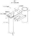
図1は、本発明の第1の実施の形態に係るアンテナ装置1を、支柱91、及び支柱91に固定された取付部材92と共に示す斜視図である。図2は、アンテナ装置1のレドーム4に収容された反射板2及び複数のアンテナ素子3を示す斜視図である。
FIG. 1 is a perspective view showing the antenna device 1 according to the first embodiment of the present invention together with a
このアンテナ装置1は、例えば携帯電話の基地局用アンテナとして用いられ、屋上等の高所に設置される。アンテナ装置1は、板状の導電性金属からなる反射板2と、反射板2に固定された複数のアンテナ素子3と、複数のアンテナ素子3が内部に配置された筒体としてのレドーム4と、レドーム4の一端部に固定された端部部材5と、端部部材5を支持する支持部材6と、端部部材5を支持部材6に対して回り止めする回り止め機構7とを備えている。
The antenna device 1 is used as an antenna for a base station of a mobile phone, for example, and is installed at a high place such as a rooftop. The antenna device 1 includes a reflecting plate 2 made of a plate-like conductive metal, a plurality of
図3(a)は、レドーム4、端部部材5、支持部材6、及び回り止め機構7をレドーム4の中心軸に沿って切断した断面図である。図3(b)は、図3(a)に示す回り止め機構7及びその周辺部を拡大して示す拡大図である。図4は、端部部材5を示し、(a)は斜視図、(b)は断面図、(c)は平面図である。図5(a)は、端部部材5及び回り止め機構7が組み合わされた支持部材6を上方から見た平面図である。図5(b)は、支持部材6を単体で示す平面図である。
FIG. 3A is a cross-sectional view of the
反射板2は、アルミニウム等の導電性の金属からなる矩形状の部材であり、図略のアース線により電気的に接地されている。反射板2は、その長手方向がレドーム4の中心軸方向に沿うようにしてレドーム4内に収容される。反射板2の長手方向の両端部には、レドーム4との固定のための固定部材21a〜21dが取り付けられている。反射板2は、固定部材21a〜21dがボルトやリベットによってレドーム4に締結されることにより、レドーム4に対して固定されている。
The reflector 2 is a rectangular member made of a conductive metal such as aluminum, and is electrically grounded by a ground wire (not shown). The reflector 2 is accommodated in the
アンテナ素子3は、それぞれ放射素子として機能する図略の配線パターンが板状の誘電体に形成されたプリント基板からなるプリントダイポールアンテナである。アンテナ素子3は、水平偏波を送信又は受信することが可能な水平偏波用アンテナ素子31と、垂直偏波を送信又は受信することが可能な垂直偏波用アンテナ素子32とを十字状に交差させて形成されている。
The
本実施の形態では、8個のアンテナ素子3が反射板2の長手方向に沿って配列されている。各アンテナ素子3の放射素子は、反射板2の反射面2aとは反対側の裏面2b側で、アンテナ素子3により送信又は受信される高周波信号を伝送する伝送線路に接続されている。
In the present embodiment, eight
アンテナ装置1は、図5(a)に示すように、アンテナ素子3が電磁波wを放射した場合に、その電磁波wの電界強度が反射板2に対して垂直な方向に強くなる指向性を有している。支柱91に複数のアンテナ装置1が取り付けられる場合には、それぞれのアンテナ装置1から放射される電磁波wが互いに異なる方向を向くように、各アンテナ装置1が取り付けられる。
As shown in FIG. 5A, the antenna device 1 has directivity that increases the electric field strength of the electromagnetic wave w in a direction perpendicular to the reflector 2 when the
レドーム4は、FRP(fiber reinforced plastics)等の絶縁性の樹脂からなる円筒状である。アンテナ装置1は、レドーム4の中心軸方向が鉛直方向となるように支柱91に取り付けられる。以下の記載において、「上」及び「下」とは、アンテナ装置1が支柱91に取り付けられた状態における鉛直方向の上下をいうものとする。
The
アンテナ装置1が支柱91に取り付けられたときのレドーム4の上端部は端部部材5により閉塞され、雨水等のレドーム4内への浸入が端部部材5により抑止される。レドーム4の下端部は開放され、この下端部の開口から伝送線路に接続される同軸ケーブル8がレドーム4内に導入される。
The upper end portion of the
端部部材5は、レドーム4の一端部に嵌合する嵌合部51と、レドーム4の外周面よりも外方に突出した突部52と、レドーム4の一端部(上端部)を閉塞する円板状の蓋部53とを有している。端部部材5は、例えば射出成型された樹脂からなる。
The
嵌合部51は、レドーム4の一端部に内嵌される円筒状であり、例えばボルト締結によってレドーム4に固定される。なお、嵌合部51をレドーム4に接着により固定してもよい。突部52は、嵌合部51の外周囲に環状(鍔状)に設けられている。本実施の形態では、突部52及び蓋部53が、1つの平坦な円盤を形成し、この円盤の嵌合部51よりも外側の部分が突部52として、また嵌合部51よりも内側の部分が蓋部53として機能する。
The
支持部材6には、レドーム4を挿通させる円形の挿通孔60が形成されている。支持部材6の挿通孔60は、レドーム4の外径よりも大きく、端部部材5の突部52の外径よりも小さい内径を有し、支持部材6を上下方向に貫通している。また、支持部材6には、取付部材92への取り付けのためのボルトを挿通させる複数のボルト挿通孔61が形成されている。
A
一方、取付部材92にも、支持部材6のボルト挿通孔61に連通するボルト挿通孔921が形成されている。支持部材6及び取付部材92は、ボルト挿通孔61,921を挿通するボルトと、このボルトに螺合するナットとの間に挟まれて締結される。
On the other hand, the
なお、支持部材6を、取付部材92を介することなく直接支柱91に固定してもよい。この場合、支持部材6は、例えば支柱91に形成されたねじ孔に螺合するボルトによって支柱91に固定される。
The
レドーム4及び端部部材5は、レドーム4が支持部材6の挿通孔60に挿通された状態で、支持部材6に対して回転可能である。支持部材6は、挿通孔60の周囲に、端部部材5の突部52が当接する当接面6a(図5(b)参照)を有している。端部部材5は、反射板2、複数のアンテナ素子3、及びレドーム4の重量を、突部52が支持部材6の当接面6aに当接することで支える。
The
レドーム4の支持部材6に対する回転位置は、アンテナ素子3からの電磁波の放射方向を調整した後に、回り止め機構7によって固定される。この調整は、例えば支柱91に取り付けられたアンテナ装置1から電磁波を放射し、その電磁波の地上の所定の場所における受信状態に基づいて行われる。
The rotational position of the
端部部材5には、目盛部5aが設けられている。本実施の形態では、目盛部5aが突部52の上面52a(当接面6aに当接する面とは反対側の面)における外周側の端部の所定の角度範囲に設けられている。目盛部5aは、例えば1°毎に形成された複数の目盛り線からなる。
The
一方、支持部材6には、指針部6bが設けられている。本実施の形態では、指針部6bが三角形状であるが、例えば1本の直線でもよく、あるいは矢印形状でもよい。指針部6bは、当接面6aの外側に設けられ、目盛部5aの1箇所を指し示している。端部部材5の支持部材6に対する相対回転位置は、指針部6bが指し示す目盛部5aの位置により認識可能である。
On the other hand, the
また、支持部材6に目盛部を設け、端部部材5に指針部を設けてもよい。この場合でも、端部部材5の支持部材6に対する相対回転位置を、指針部が指し示す目盛部の位置により認識可能である。すなわち、端部部材5及び支持部材6には、一方の部材に目盛部が設けられると共に、他方の部材に指針部が設けられていればよい。
Further, the
本実施の形態では、回り止め機構7が金具71及びボルト72からなる。金具71は、支持部材6及び端部部材5の突部52を挟む位置に配置される一対の側板部711,712、及び一対の側板部711,712を連結する連結部713を有する。以下、一対の側板部711,712のうち、端部部材5の突部52に対向する側板部711を第1の側板部711とし、支持部材6に対向する側板部712を第2の側板部712とする。第1の側板部711には、ボルト72の軸部721が螺合するねじ孔710が形成されている。
In the present embodiment, the detent mechanism 7 includes a
ボルト72は、頭部722が第1の側板部711に接するまでねじ孔710にねじ込まれている。ボルト72の軸部721は、ねじ孔710を貫通して端部部材5の突部52の上面52aに当接する。これにより、ボルト72の締め付け力によって端部部材5と支持部材6との相対回転が規制される。
The
(実施の形態の効果)
以上説明した実施の形態によれば、以下の効果を得ることができる。
(Effect of embodiment)
According to the embodiment described above, the following effects can be obtained.
(1)支持部材6に対して端部部材5を自在に回転させることができる。すなわち、例えば複数のボルト挿通孔のうち選択された1つのボルト挿通孔にボルトを挿通させることによって取り付け角度を調整する場合に比較して、複数のアンテナ素子3から放射される電磁波の放射方向をより細かい角度単位で調整することが可能となる。特に、本実施の形態では、レドーム4が円筒状であり、支持部材6の挿通孔60が円形であるので、複数のアンテナ素子3の放射方向(メインビームの放射方向)を無段階に調節することができる。
(1) The
(2)端部部材5は、反射板2、複数のアンテナ素子3、及びレドーム4の重量を支えるので、これらの部材の支持構造を容易化することができる。
(2) Since the
(3)端部部材5は蓋部53を有しているので、アンテナ装置1が屋根のない屋外に設置されたとしても、レドーム4の上端開口部からの雨水等の浸入を防ぐことができる。
(3) Since the
(4)端部部材5に目盛部5aが設けられ、支持部材6に指針部6bが設けられているので、端部部材5の支持部材6に対する相対回転位置の調整が容易となる。
(4) Since the
(5)回り止め機構7は、支持部材6及び端部部材5の突部52を挟む位置に配置される第1及び第2の側板部711,712を有する金具71、及び第1の側板部711のねじ孔710に螺合するボルト72からなるので、簡素な構成で端部部材5を支持部材6に対して回り止めすることができる。
(5) The rotation prevention mechanism 7 includes a
[第2の実施の形態]
次に、図6を参照して本発明の第2の実施の形態について説明する。第2の実施の形態は、端部部材5を支持部材6に対して回り止めする回り止め機構7Aの構成が第1の実施の形態とは異なり、その他の構成については共通である。したがって、この違いの部分について説明し、その他の構成については詳細な説明を省略する。また、図6の図示内容のうち、第1の実施の形態について説明したものと共通する構成要素については、第1の実施の形態と同一の符号を付して重複した説明を省略する。
[Second Embodiment]
Next, a second embodiment of the present invention will be described with reference to FIG. The second embodiment is different from the first embodiment in the configuration of a
本実施の形態に係る回り止め機構7Aは、端部部材5の突部52に設けられた複数の第1の噛み合い歯521、及び支持部材6に設けられ、複数の第2の噛み合い歯62からなる。第1の噛み合い歯521は、突部52の外周端部から下方(支持部材6側)に向かって設けられ、第2の噛み合い歯62は、突部52に対向する支持部材6の上面6cから上方(突部52側)に向かって設けられている。複数の第1の噛み合い歯521は、突部52の外周端部に全周にわたって設けられ、複数の第2の噛み合い歯62は、レドーム4を挿通させる挿通孔60を囲むように、環状に設けられている。
The
図6(a)は、第1の噛み合い歯521と第2の噛み合い歯62とが噛み合わされていない状態を示し、図6(b)は、第1の噛み合い歯521と第2の噛み合い歯62とが噛み合わされた状態を示している。図6(b)に示すように、第1の噛み合い歯521と第2の噛み合い歯62とが噛み合わされると、端部部材5が支持部材6に対して回り止めされる。
FIG. 6A shows a state where the
本実施の形態では、周方向に隣り合う第1の噛み合い歯521及び第2の噛み合い歯62の間隔に対応する角度単位で複数のアンテナ素子3から放射される電磁波の放射方向を調整することができる。このため、第1の実施の形態と同様に、例えば複数のボルト挿通孔のうち選択された1つのボルト挿通孔にボルトを挿通させることによって取り付け角度を調整する場合に比較して、複数のアンテナ素子3から放射される電磁波の放射方向をより細かい角度単位で調整することが可能となる。
In the present embodiment, the radiation direction of the electromagnetic waves radiated from the plurality of
(実施の形態のまとめ)
次に、以上説明した実施の形態から把握される技術思想について、実施の形態における符号等を援用して記載する。ただし、以下の記載における各符号は、特許請求の範囲における構成要素を実施の形態に具体的に示した部材等に限定するものではない。
(Summary of embodiment)
Next, the technical idea grasped from the embodiment described above will be described with reference to the reference numerals in the embodiment. However, each reference numeral in the following description does not limit the constituent elements in the claims to members or the like specifically shown in the embodiment.
[1]複数のアンテナ素子(3)と、前記複数のアンテナ素子(3)が内部に配置された筒体(レドーム4)と、前記筒体(4)の一端部に固定され、前記筒体(4)の外周面よりも外方に突出した突部(52)を有する端部部材(5)と、前記筒体(4)が挿通される挿通孔(60)が形成され、前記挿通孔(60)の周囲に前記端部部材(5)の前記突部(52)が当接する当接面(6a)を有する支持部材(6)とを備え、前記筒体(4)及び前記端部部材(5)は、前記筒体(4)が前記挿通孔(60)に挿通された状態で前記支持部材(5)に対して回転可能であり、前記端部部材(5)は、前記複数のアンテナ素子(3)及び前記筒体(4)の重量を前記突部(52)が前記当接面(6a)に当接することで支える、アンテナ装置(1)。 [1] A plurality of antenna elements (3), a cylinder (radome 4) in which the plurality of antenna elements (3) are disposed, and one end of the cylinder (4) are fixed to the cylinder. An end member (5) having a protrusion (52) protruding outward from the outer peripheral surface of (4) and an insertion hole (60) through which the cylindrical body (4) is inserted are formed, and the insertion hole A support member (6) having an abutting surface (6a) with which the protrusion (52) of the end member (5) abuts around (60), and the cylindrical body (4) and the end portion The member (5) is rotatable with respect to the support member (5) in a state where the cylindrical body (4) is inserted through the insertion hole (60), and the end member (5) includes the plurality of end members (5). The antenna element (3) and the cylindrical body (4) are supported by supporting the weight of the protrusion (52) by contacting the contact surface (6a). (1).
[2]前記端部部材(5)は、前記筒体(4)の開口を覆う蓋部(53)をさらに有する、前記[1]に記載のアンテナ装置(1)。 [2] The antenna device (1) according to [1], wherein the end member (5) further includes a lid portion (53) that covers an opening of the cylindrical body (4).
[3]前記端部部材(5)及び前記支持部材(6)には、一方の部材に目盛部(5a)が設けられると共に他方の部材に指針部(6b)が設けられ、前記指針部(6b)が指し示す目盛部(5a)の位置により、前記端部部材(5)の前記支持部材(6)に対する相対回転位置を認識可能である、前記[1]又は[2]に記載のアンテナ装置(1)。 [3] The end member (5) and the support member (6) are provided with a scale portion (5a) on one member and a pointer portion (6b) on the other member. The antenna device according to [1] or [2], wherein a relative rotational position of the end member (5) with respect to the support member (6) can be recognized by a position of the scale portion (5a) indicated by 6b). (1).
[4]前記端部部材(5)を前記支持部材(6)に対して回り止めする回り止め機構(7)をさらに備えた、前記[1]乃至[3]の何れか1つに記載のアンテナ装置(1)。 [4] The device according to any one of [1] to [3], further including a detent mechanism (7) that prevents the end member (5) from rotating with respect to the support member (6). Antenna device (1).
[5]前記回り止め機構(7)は、前記支持部材(6)及び前記端部部材(5)の前記突部(52)を挟む位置に配置される一対の側板部(711,712)、及び前記一対の側板部(711,712)を連結する連結部(713)を有する金具(71)と、前記一対の側板部(711,712)のうち何れかの側板部(711)に形成されたねじ孔(710)に螺合するボルト(72)とを有する、前記[4]に記載のアンテナ装置(1)。 [5] The anti-rotation mechanism (7) includes a pair of side plate portions (711, 712) disposed at positions sandwiching the protrusion (52) of the support member (6) and the end member (5), And a metal fitting (71) having a connecting portion (713) for connecting the pair of side plate portions (711, 712), and a side plate portion (711) of the pair of side plate portions (711, 712). The antenna device (1) according to [4], further including a bolt (72) that is screwed into the screw hole (710).
[6]前記回り止め機構(7A)は、前記端部部材(5)の前記突部(52)に設けられた第1の噛み合い歯(521)、及び前記支持部材(6)に設けられ、前記第1の噛み合い歯(521)に噛み合う第2の噛み合い歯(62)からなる、前記[4]に記載のアンテナ装置(1)。 [6] The detent mechanism (7A) is provided on the first meshing tooth (521) provided on the protrusion (52) of the end member (5), and on the support member (6). The antenna device (1) according to [4], including a second meshing tooth (62) meshing with the first meshing tooth (521).
以上、本発明の実施の形態を説明したが、上記に記載した実施の形態は特許請求の範囲に係る発明を限定するものではない。また、実施の形態の中で説明した特徴の組合せの全てが発明の課題を解決するための手段に必須であるとは限らない点に留意すべきである。 While the embodiments of the present invention have been described above, the embodiments described above do not limit the invention according to the claims. In addition, it should be noted that not all the combinations of features described in the embodiments are essential to the means for solving the problems of the invention.
1…アンテナ装置
2…反射板
3…アンテナ素子
4…レドーム(筒体)
5…端部部材
52…突部
521…第1の噛み合い歯
53…蓋部
5a…目盛部
6…支持部材
60…挿通孔
61…ボルト挿通孔
62…第2の噛み合い歯
6a…当接面
6b…指針部
7,7A…回り止め機構
71…金具
711,712…側板部
713…連結部
72…ボルト
DESCRIPTION OF SYMBOLS 1 ... Antenna apparatus 2 ... Reflecting
5 ...
Claims (6)
前記複数のアンテナ素子が内部に配置された筒体と、
前記筒体の一端部に固定され、前記筒体の外周面よりも外方に突出した突部を有する端部部材と、
前記筒体が挿通される挿通孔が形成され、前記挿通孔の周囲に前記端部部材の前記突部が当接する当接面を有する支持部材とを備え、
前記筒体及び前記端部部材は、前記筒体が前記挿通孔に挿通された状態で前記支持部材に対して回転可能であり、
前記端部部材は、前記複数のアンテナ素子及び前記筒体の重量を前記突部が前記当接面に当接することで支える、
アンテナ装置。 A plurality of antenna elements;
A cylindrical body in which the plurality of antenna elements are disposed;
An end member having a protrusion fixed to one end of the cylinder and protruding outward from the outer peripheral surface of the cylinder;
An insertion hole into which the cylindrical body is inserted, and a support member having a contact surface with which the protrusion of the end member contacts around the insertion hole,
The cylindrical body and the end member are rotatable with respect to the support member in a state where the cylindrical body is inserted through the insertion hole,
The end member supports the weight of the plurality of antenna elements and the cylindrical body by the protrusion abutting against the abutting surface,
Antenna device.
請求項1に記載のアンテナ装置。 The end member further has a lid that covers the opening of the cylindrical body,
The antenna device according to claim 1.
請求項1又は2に記載のアンテナ装置。 In the end member and the support member, a scale portion is provided on one member and a pointer portion is provided on the other member, and the support member of the end member is determined by the position of the scale portion indicated by the pointer portion. Recognizable relative rotational position with respect to
The antenna device according to claim 1 or 2.
請求項1乃至3の何れか1項に記載のアンテナ装置。 A detent mechanism for preventing the end member from rotating with respect to the support member;
The antenna device according to any one of claims 1 to 3.
請求項4に記載のアンテナ装置。 The anti-rotation mechanism includes a pair of side plate portions arranged at positions sandwiching the protrusions of the support member and the end member, a metal fitting having a connecting portion connecting the pair of side plate portions, and the pair of side plates. A bolt that is screwed into a screw hole formed in any of the side plate portions of the portion,
The antenna device according to claim 4.
請求項4に記載のアンテナ装置。 The rotation preventing mechanism includes a first meshing tooth provided on the protrusion of the end member and a second meshing tooth provided on the support member and meshing with the first meshing tooth.
The antenna device according to claim 4.
Priority Applications (1)
| Application Number | Priority Date | Filing Date | Title |
|---|---|---|---|
| JP2016075836A JP2017188770A (en) | 2016-04-05 | 2016-04-05 | Antenna device |
Applications Claiming Priority (1)
| Application Number | Priority Date | Filing Date | Title |
|---|---|---|---|
| JP2016075836A JP2017188770A (en) | 2016-04-05 | 2016-04-05 | Antenna device |
Publications (1)
| Publication Number | Publication Date |
|---|---|
| JP2017188770A true JP2017188770A (en) | 2017-10-12 |
Family
ID=60044260
Family Applications (1)
| Application Number | Title | Priority Date | Filing Date |
|---|---|---|---|
| JP2016075836A Pending JP2017188770A (en) | 2016-04-05 | 2016-04-05 | Antenna device |
Country Status (1)
| Country | Link |
|---|---|
| JP (1) | JP2017188770A (en) |
-
2016
- 2016-04-05 JP JP2016075836A patent/JP2017188770A/en active Pending
Similar Documents
| Publication | Publication Date | Title |
|---|---|---|
| US6987489B2 (en) | Electronically scanning direction finding antenna system | |
| US8094084B2 (en) | Omnidirectional antenna for indoor and outdoor use | |
| US11695223B2 (en) | Antenna array | |
| US11631929B2 (en) | Fastening device and associated method | |
| JP3181923B2 (en) | Microwave transceiver, antenna system with adjustable installation and alignment mechanism | |
| KR102005101B1 (en) | Folded reflectarray antenna using active phased array feed | |
| US20040217908A1 (en) | Adjustable reflector system for fixed dipole antenna | |
| JPH09246847A (en) | Single wire spiral antenna | |
| JP6313449B2 (en) | Antenna system | |
| JPWO2018212306A1 (en) | In-vehicle antenna device | |
| EP3185357B1 (en) | Antenna device | |
| US3299429A (en) | Vertical array of folded dipoles adjustably mounted on support mast | |
| US10923826B2 (en) | Double helical antenna | |
| JP2017188770A (en) | Antenna device | |
| US5440319A (en) | Integrated microwave antenna/downconverter | |
| JP4878024B2 (en) | antenna | |
| WO2015159871A1 (en) | Antenna and sector antenna | |
| CA2064295C (en) | Microwave polarizing lens structure | |
| JP2017228840A (en) | Retainer of antenna device | |
| US5565880A (en) | Antenna for portable telecommunication systems | |
| JP2010050791A (en) | Variable directivity antenna | |
| JP7040951B2 (en) | Antenna device | |
| CN210224267U (en) | Oscillator antenna convenient for adjusting direction signal intensity | |
| JP2019068329A (en) | Circularly polarized wave antenna, and diversity communication system | |
| CN210200957U (en) | Direction-adjustable bidirectional coverage directional antenna |
Legal Events
| Date | Code | Title | Description |
|---|---|---|---|
| A711 | Notification of change in applicant |
Free format text: JAPANESE INTERMEDIATE CODE: A711 Effective date: 20171215 |