JP2017185636A - Electronic apparatus and control method - Google Patents
Electronic apparatus and control method Download PDFInfo
- Publication number
- JP2017185636A JP2017185636A JP2016074037A JP2016074037A JP2017185636A JP 2017185636 A JP2017185636 A JP 2017185636A JP 2016074037 A JP2016074037 A JP 2016074037A JP 2016074037 A JP2016074037 A JP 2016074037A JP 2017185636 A JP2017185636 A JP 2017185636A
- Authority
- JP
- Japan
- Prior art keywords
- power
- state
- condition
- saving mode
- power saving
- Prior art date
- Legal status (The legal status is an assumption and is not a legal conclusion. Google has not performed a legal analysis and makes no representation as to the accuracy of the status listed.)
- Pending
Links
Images


Classifications
-
- H—ELECTRICITY
- H04—ELECTRIC COMMUNICATION TECHNIQUE
- H04N—PICTORIAL COMMUNICATION, e.g. TELEVISION
- H04N1/00—Scanning, transmission or reproduction of documents or the like, e.g. facsimile transmission; Details thereof
- H04N1/00885—Power supply means, e.g. arrangements for the control of power supply to the apparatus or components thereof
- H04N1/00888—Control thereof
- H04N1/00891—Switching on or off, e.g. for saving power when not in use
-
- G—PHYSICS
- G06—COMPUTING; CALCULATING OR COUNTING
- G06K—GRAPHICAL DATA READING; PRESENTATION OF DATA; RECORD CARRIERS; HANDLING RECORD CARRIERS
- G06K15/00—Arrangements for producing a permanent visual presentation of the output data, e.g. computer output printers
-
- G—PHYSICS
- G06—COMPUTING; CALCULATING OR COUNTING
- G06K—GRAPHICAL DATA READING; PRESENTATION OF DATA; RECORD CARRIERS; HANDLING RECORD CARRIERS
- G06K15/00—Arrangements for producing a permanent visual presentation of the output data, e.g. computer output printers
- G06K15/40—Details not directly involved in printing, e.g. machine management, management of the arrangement as a whole or of its constitutive parts
- G06K15/4055—Managing power consumption, e.g. standby mode
- G06K15/406—Wake-up procedures
-
- H—ELECTRICITY
- H04—ELECTRIC COMMUNICATION TECHNIQUE
- H04N—PICTORIAL COMMUNICATION, e.g. TELEVISION
- H04N1/00—Scanning, transmission or reproduction of documents or the like, e.g. facsimile transmission; Details thereof
- H04N1/00002—Diagnosis, testing or measuring; Detecting, analysing or monitoring not otherwise provided for
- H04N1/00007—Diagnosis, testing or measuring; Detecting, analysing or monitoring not otherwise provided for relating to particular apparatus or devices
- H04N1/00015—Reproducing apparatus
-
- H—ELECTRICITY
- H04—ELECTRIC COMMUNICATION TECHNIQUE
- H04N—PICTORIAL COMMUNICATION, e.g. TELEVISION
- H04N1/00—Scanning, transmission or reproduction of documents or the like, e.g. facsimile transmission; Details thereof
- H04N1/00885—Power supply means, e.g. arrangements for the control of power supply to the apparatus or components thereof
- H04N1/00888—Control thereof
- H04N1/00896—Control thereof using a low-power mode, e.g. standby
Abstract
Description
本発明は、電子機器、及び制御方法に関する。 The present invention relates to an electronic device and a control method.
省電力モードを有する画像形成装置が知られている(例えば、特許文献1)。この画像
形成装置は、例えば、印刷指示を受けた場合に、省電力モードを解除し、印刷処理を実行
する。
An image forming apparatus having a power saving mode is known (for example, Patent Document 1). For example, when receiving a print instruction, the image forming apparatus cancels the power saving mode and executes a print process.
近年のプリンターは、自動電源オフ機能を備えるものがある。このプリンターは、例え
ば、所定時間の経過等の条件が成立した場合に、電源オフ状態に移行する。また、近年の
プリンターは、自動電源オン機能を備えるものがある。このプリンターは、例えば、通常
の省電力モードよりも低消費電力の待機モードで印刷処理要求を待ち、印刷処理要求を受
け付けた場合に、アイドル状態に移行して印刷処理を実行する。
Some recent printers have an automatic power-off function. This printer shifts to a power-off state when, for example, a condition such as elapse of a predetermined time is satisfied. Some recent printers have an automatic power-on function. For example, this printer waits for a print processing request in a standby mode that consumes less power than the normal power saving mode, and when accepting the print processing request, shifts to an idle state and executes the print processing.
自動電源オフ機能と自動電源オン機能の両方を有するプリンターを想定する。このプリ
ンターは、例えば、待機モード中に所定の条件が成立すると、電源オフ状態への移行処理
を開始してしまう。
Assume a printer having both an automatic power off function and an automatic power on function. For example, when a predetermined condition is satisfied during the standby mode, this printer starts the process of shifting to the power-off state.
本発明の目的は、自動電源オフ機能と自動電源オン機能の両方を適切に動作させること
にある。
An object of the present invention is to appropriately operate both the automatic power-off function and the automatic power-on function.
上記の課題を解決する本発明の一態様は、通常モード、及び前記通常モードよりも低消
費電力の省電力モードで動作する電子機器であって、制御部を有し、前記制御部は、電源
オフ状態に移行するための第1の条件が成立した後、第1の省電力モードに移行するため
の第2の条件が成立する場合、前記第1の省電力モードに移行し、前記第2の条件が成立
しない場合、前記電源オフ状態に移行し、前記第1の省電力モードの間に前記第1の条件
が成立しても、前記電源オフ状態に移行せずに前記第1の省電力モードを継続し、前記第
1の省電力モードの間に第3の条件が成立した場合に、前記通常モードに移行する。これ
により、電子機器は、第1の省電力モードの間に電源オフ処理を開始せずに、第1の省電
力モードを継続することができる。
One embodiment of the present invention for solving the above problems is an electronic device that operates in a normal mode and a power saving mode that consumes less power than the normal mode, and includes a control unit, and the control unit includes a power source. After the first condition for shifting to the off state is satisfied, when the second condition for shifting to the first power saving mode is satisfied, the mode shifts to the first power saving mode, and the second If the above condition is not satisfied, the state shifts to the power-off state, and even if the first condition is satisfied during the first power-saving mode, the first power-saving state does not shift to the first power-saving state. When the power mode is continued and the third condition is satisfied during the first power saving mode, the mode is shifted to the normal mode. Thereby, the electronic device can continue the first power saving mode without starting the power-off process during the first power saving mode.
上記の電子機器は、少なくとも1つの通信接続を確立可能であり、前記制御部は、前記
第1の条件として、前記通信接続の全て又は前記通信接続のうちの所定の1つ以上の通信
接続が切断されたか否かを判定してもよい。これにより、電子機器は、印刷指示等の処理
要求を受け付けることができなくなった場合に電源オフ状態に移行する、利便性の高い機
能を提供できる。
The electronic device is capable of establishing at least one communication connection, and the control unit has, as the first condition, all of the communication connections or one or more predetermined communication connections of the communication connections. It may be determined whether or not it has been cut. Accordingly, the electronic device can provide a highly convenient function that shifts to a power-off state when a processing request such as a print instruction cannot be received.
上記の電子機器において、前記制御部は、前記第2の条件として、前記第1省電力モー
ドの設定が有効か否かを判定してもよい。これにより、電子機器は、適切に自動電源オン
機能(第1の省電力モード)を実行することができる。
In the electronic apparatus, the control unit may determine whether the setting of the first power saving mode is valid as the second condition. Thereby, the electronic device can appropriately execute the automatic power-on function (first power saving mode).
上記の電子機器において、前記制御部は、前記第3の条件として、外部機器からの要求
又はユーザーの操作を受け付けたか否かを判定してもよい。これにより、電子機器は、低
消費電力状態で待機して要求を受け付けることができる。
In the above electronic device, the control unit may determine whether a request from an external device or a user operation is accepted as the third condition. Thereby, the electronic device can stand by in a low power consumption state and accept a request.
上記の電子機器において、前記制御部は、前記電源オフ状態、又は前記第1の省電力モ
ードに移行する前に、前記通常モードよりも低消費電力であり前記第1の省電力モードよ
りも高消費電力である第2の省電力モードに移行し、前記第1の条件及び前記第2の条件
の成立を判定してもよい。これにより、電子機器は、第1の省電力モード又は電源オフ状
態移行する前に、低消費電力状態で判定を行うことができる。
In the electronic apparatus, the control unit consumes less power than the normal mode and higher than the first power saving mode before shifting to the power-off state or the first power saving mode. A transition to the second power saving mode, which is power consumption, may be made to determine whether the first condition and the second condition are satisfied. Accordingly, the electronic device can make a determination in the low power consumption state before shifting to the first power saving mode or the power-off state.
上記の電子機器は、無線接続を含む複数の前記通信接続を確立可能であり、前記制御部
は、少なくとも前記無線接続が切断されている場合に、前記第1の条件が成立したと判定
してもよい。これにより、電子機器は、無線通信機能が有効である場合には、電源オフ状
態に移行しないように制御することができる。
The electronic device can establish a plurality of the communication connections including a wireless connection, and the control unit determines that the first condition is satisfied at least when the wireless connection is disconnected. Also good. Thereby, the electronic device can be controlled not to shift to the power-off state when the wireless communication function is valid.
上記の課題を解決する本発明の他の態様は、通常モード、及び前記通常モードよりも低
消費電力の省電力モードで動作する電子機器の制御方法であって、前記電子機器は、電源
オフ状態に移行するための第1の条件が成立した後、第1の省電力モードに移行するため
の第2の条件が成立する場合、前記第1の省電力モードに移行し、前記第2の条件が成立
しない場合、前記電源オフ状態に移行し、前記第1の省電力モードの間に前記第1の条件
が成立しても、前記電源オフ状態に移行せずに前記第1の省電力モードを継続し、前記第
1の省電力モードの間に第3の条件が成立した場合に、前記通常モードに移行する。これ
により、電子機器は、第1の省電力モードの間に電源オフ処理を開始せずに、第1の省電
力モードを継続することができる。
Another aspect of the present invention for solving the above problem is a control method of an electronic device that operates in a normal mode and a power saving mode with lower power consumption than the normal mode, wherein the electronic device is in a power-off state. When the second condition for shifting to the first power saving mode is satisfied after the first condition for shifting to the first condition is satisfied, the second condition is set for shifting to the first power saving mode. Is not established, the first power saving mode is entered without shifting to the power off state even if the first condition is established during the first power saving mode. And when the third condition is satisfied during the first power saving mode, the mode is shifted to the normal mode. Thereby, the electronic device can continue the first power saving mode without starting the power-off process during the first power saving mode.
本発明の一実施形態について、図面を参照して説明する。本実施形態は、電子機器の一
例であるプリンターに関する。
An embodiment of the present invention will be described with reference to the drawings. The present embodiment relates to a printer that is an example of an electronic apparatus.
図1は、本発明の一実施形態に係るプリンターの構成の一例を示すブロック図である。 FIG. 1 is a block diagram illustrating an example of the configuration of a printer according to an embodiment of the invention.
プリンター1は、自動電源オフ機能と自動電源オン機能の両方を有する。プリンター1
は、例えば、全ての通信接続が切断されている場合に、電源オフ状態への移行を開始する
。また、プリンター1は、自動電源オン機能が有効な場合は、電源オン待機状態に移行す
る。これらの機能については、後に詳述する。
The
For example, when all communication connections are disconnected, the transition to the power-off state is started. Further, when the automatic power-on function is valid, the
プリンター1は、コントローラー2(本発明の「制御部」に相当する)と、印刷エンジ
ン4と、操作パネル5と、無線通信部6と、有線通信部7と、接続インターフェイス8(
接続I/F)とを有する。
The
Connection I / F).
コントローラー2は、プリンター1の動作を統合的に制御する。コントローラー2は、
例えば、CPU(Central Processing Unit)等の演算装置を備えるSoC3(System on
a Chip)、RAM(Random Access Memory)等の揮発性の記憶装置、ROM(Read Only
Memory)等の不揮発性の記憶装置、コントローラー2と他のユニットを接続するインタ
ーフェイス回路、これらを互いに接続するバス、などを備えるコンピューターによって実
現することができる。もちろん、コントローラー2は、画像処理回路など各種の処理回路
を備えていてもよい。SoC3は、例えば、メインCPU31と、サブCPU32とを備
える。サブCPU32は、例えば、メインCPU31よりも小さい回路規模を有し、メイ
ンCPU31よりも低消費電力で動作する。
The
For example, SoC3 (System on
a Chip), volatile storage devices such as RAM (Random Access Memory), ROM (Read Only)
And a non-volatile storage device such as a memory, an interface circuit that connects the
上記のコントローラー2の機能の少なくとも一部は、例えば、CPUがROMに格納さ
れた1つ以上のプログラムをRAMに読み出して実行することによって実現することがで
きる。各プログラムは、例えば持ち運び可能な記憶媒体から読み出してプリンター1にイ
ンストールしたり、ネットワーク上のサーバーからダウンロードしてプリンター1にイン
ストールしたりすることができる。コントローラー2の機能の少なくとも一部は、例えば
、画像処理回路等の処理回路によって実現してもよい。コントローラー2の機能の少なく
とも一部は、例えば、CPU及び処理回路の両方によって実現されてもよい。
At least a part of the functions of the
印刷エンジン4は、コントローラー2からの指示に従って印刷媒体に画像を形成する。
印刷エンジン4は、例えば、インクジェット方式、レーザー方式等の方式の印刷エンジン
であり、機械部品、センサー、モーター、駆動回路、制御回路等により構成される。
The
The
操作パネル5は、ユーザーの操作入力を受け付け、操作に応じた操作信号をコントロー
ラー2に出力する。また、操作パネル5は、コントローラー2の処理結果を、文字、グラ
フ、表、アニメーション、その他の画像として表示する。操作パネル5は、コントローラ
ー2の処理結果を、音声出力してもよい。操作パネル5は、例えば、キー、タッチセンサ
ー、タッチパネルなどを含む入力装置と、例えば、LCD(Liquid Crystal Display)、
OLED(Organic Electro-Luminescence Display)、スピーカーなどを含む出力装置と
によって実現することができる。
The
This can be realized by an OLED (Organic Electro-Luminescence Display), an output device including a speaker and the like.
無線通信部6は、例えば、無線LAN規格であるWi−Fi規格に準拠した通信機能を
実装した通信モジュールである。コントローラー2は、無線通信部6を介して、PC(Pe
rsonal Computer)等の外部機器と通信することができる。
The
rsonal Computer) and the like.
有線通信部7は、例えば、有線LAN規格に準拠した通信機能を実装した通信モジュー
ルである。コントローラー2は、有線通信部7を介して、PC等の外部機器と通信するこ
とができる。
The
接続I/F8は、例えば、USB(Universal Serial Bus)規格に準拠した接続及び通
信を行うインターフェイス装置である。コントローラー2は、接続I/F8を介して、接
続I/F8に接続されたデバイス(例えば、フラッシュROMを搭載した記憶媒体)にア
クセスし、デバイスから情報を読み出すことができる。
The connection I /
本実施形態のプリンター1は、複数の動作状態(「動作モード」ともいう)で動作する
ことができる。動作状態は、消費電力の高い順に、例えば、下記の4つの状態を含む。
(1)アイドル状態(本発明の「通常モード」に相当する)
(2)スリープ状態(本発明の「第2の省電力モード」に相当する)
(3)電源オン待機状態(本発明の「第1の省電力モード」に相当する)
(4)電源オフ状態(本発明の「電源オフ状態」に相当する)
The
(1) Idle state (corresponding to “normal mode” of the present invention)
(2) Sleep state (corresponding to “second power saving mode” of the present invention)
(3) Power-on standby state (corresponding to “first power saving mode” of the present invention)
(4) Power off state (corresponding to “power off state” of the present invention)
アイドル状態(1)は、例えば、プリンター1が印刷指示を受け付けて即印刷処理を実
行可能な状態である。例えば、コントローラー2、印刷エンジン4、操作パネル5、無線
通信部6、有線通信部7、及び接続I/F8には、電源から電力が供給され、いつでも使
える状態である。
The idle state (1) is, for example, a state in which the
スリープ状態(2)は、例えば、プリンター1の一部のユニットが省電力状態に設定さ
れた状態である。例えば、印刷エンジン4、及び操作パネル5は、省電力状態に設定され
る。印刷エンジン4は、例えば、一部の機構を停止状態にする。操作パネル5は、例えば
、操作パネル5のディスプレイのバックライトを消灯する。
The sleep state (2) is a state in which some units of the
電源オン待機状態(3)は、例えば、プリンター1の一部のユニットが電源オフ状態に
設定され、メインCPU31も電源オフ状態に設定された状態である。例えば、印刷エン
ジン4、操作パネル5、コントローラー2の備えるRAM等の記憶装置、及びメインCP
U31は、電源オフ状態に設定される。無線通信部6、有線通信部7、及び接続I/F8
は、例えば、省電力状態に設定される。この状態では、サブCPU32は、起動しており
、例えば、電源ボタン等の所定ボタンの操作、無線通信部6又は有線通信部7から出力さ
れる所定信号(例えば、LANからのウェイクアップ信号に応じて出力される信号)、接
続I/F8へのデバイスの抜き差し等を監視している。
In the power-on standby state (3), for example, some units of the
U31 is set to a power-off state.
Is set to a power saving state, for example. In this state, the
電源オフ状態(4)は、プリンター1の電源がオフされた状態である。プリンター1は
、例えば、電源ボタン等の所定ボタンが操作された場合に、起動し、アイドル状態(1)
に復帰する。
The power off state (4) is a state in which the
Return to.
なお、プリンター1の無線通信機能は、有効又は無効に設定できてもよい。無線通信機
能が無効に設定されている場合、無線通信部6は、アイドル状態(1)及びスリープ状態
(2)において、例えば電源オフ状態に設定される。プリンター1の有線通信機能は、有
効又は無効に設定できてもよい。有線通信機能が無効に設定されている場合、有線通信部
7は、アイドル状態(1)及びスリープ状態(2)において、例えば電源オフ状態に設定
される。接続I/F8の機能は、有効又は無効に設定できてもよい。接続I/F8の機能
が無効に設定されている場合、接続I/F8は、アイドル状態(1)及びスリープ状態(
2)において、例えば電源オフ状態に設定される。
Note that the wireless communication function of the
In 2), for example, the power is turned off.
SoC3は、上述のプリンター1の各動作状態の遷移を制御する。この点については、
以下に詳述する。
The
This will be described in detail below.
図2は、プリンターの各動作状態の遷移例を示す状態遷移図である。 FIG. 2 is a state transition diagram illustrating a transition example of each operation state of the printer.
アイドル状態(1)とスリープ状態(2)は、相互に遷移可能である。スリープ状態(
2)と電源オン待機状態(3)は、相互に遷移可能である。電源オフ状態(4)は、スリ
ープ状態(2)から遷移可能である。電源オフ状態(4)は、アイドル状態(1)から遷
移可能であってもよい。アイドル状態(1)は、電源オフ状態(4)から遷移可能である
。電源オフ状態(4)は、電源オン待機状態(3)から遷移することができない。
The idle state (1) and the sleep state (2) can transition to each other. Sleep state (
2) and the power-on standby state (3) can be shifted to each other. The power-off state (4) can transition from the sleep state (2). The power-off state (4) may be transitionable from the idle state (1). The idle state (1) can transition from the power-off state (4). The power-off state (4) cannot transition from the power-on standby state (3).
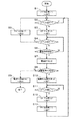
図3は、プリンターの動作の一例を示すフローチャートである。図3は、プリンター1
の動作状態の遷移を制御するコントローラー2の処理を示している。図3は、自動電源オ
フ機能が有効に設定され、自動電源オン機能が有効又は無効に設定されている場合を示し
ている。
FIG. 3 is a flowchart illustrating an example of the operation of the printer. FIG. 3 shows the
The process of the
プリンター1が電源オンにされると、コントローラー2は、アイドル状態(1)に遷移
する(ステップS1)。例えば、コントローラー2、印刷エンジン4、操作パネル5、無
線通信部6、有線通信部7、及び接続I/F8は、電力が供給され、起動する。なお、無
線通信機能が無効に設定されている場合、無線通信部6は、例えば電源オフ状態に設定さ
れる。また、有線通信機能が無効に設定されている場合、有線通信部7は、例えば電源オ
フ状態に設定される。また、接続I/F8の機能が無効に設定されている場合、接続I/
F8は、例えば電源オフ状態に設定される。
When the
F8 is set to a power-off state, for example.
アイドル状態(1)のコントローラー2は、イベントを監視する(ステップS2)。例
えば、メインCPU31は、印刷指示等の処理要求をイベントとして監視する。処理要求
を検出した場合(ステップS2でY)、メインCPU31は、当該処理要求に応じた処理
(例えば、印刷処理)を実行し、監視を続行する。一方、所定時間(例えば、5分)以上
の間、処理要求を検出しなかった場合(ステップS2でN)、メインCPU31は、処理
をステップS3に進める。
The
所定時間以上の間イベントが検出されなかった場合(ステップS2でN)、コントロー
ラー2は、スリープ状態(2)に移行する(ステップS3)。例えば、メインCPU31
は、上述したようにプリンター1の一部のユニットを省電力状態に設定する。
If no event is detected for a predetermined time or longer (N in step S2), the
As described above, some units of the
スリープ状態(2)のコントローラー2は、イベントを監視する(ステップS4)。例
えば、メインCPU31は、印刷指示等の処理要求をイベントとして監視する。処理要求
を検出した場合(ステップS4でY)、メインCPU31は、処理をステップS5に進め
る。処理要求を検出していない場合(ステップS4でN)、メインCPU31は、処理を
ステップS6に進める。
The
イベントを検出した場合(ステップS4でY)、コントローラー2は、アイドル状態(
1)に移行する(ステップS5)。例えば、メインCPU31は、プリンター1の一部の
省電力状態のユニットを通常状態に設定する。それから、メインCPU31は、ステップ
S4で検出されたイベントに応じた処理(例えば、印刷処理等)を実行し、再びステップ
S2の処理を実行する。
When an event is detected (Y in step S4), the
1) (Step S5). For example, the
イベントを検出していない場合(ステップS4でN)、コントローラー2は、通信接続
が切断されているか否かを判定する(ステップS6)。
When the event is not detected (N in Step S4), the
本実施形態の自動電源オフ機能では、全ての通信接続(無線通信部6の無線接続、有線
通信部7の有線接続、及び接続I/F8のデバイス接続を含む)が切断された状態で、所
定時間(例えば30分)経過した場合に、プリンター1の電源オフ処理が実行される。
In the automatic power off function of the present embodiment, all communication connections (including the wireless connection of the
無線接続が切断された状態とは、例えば、無線通信機能が無効に設定されることにより
無線通信部6が信号を送受信しないように物理的に無効にされた状態である。有線接続が
切断された状態とは、例えば、有線通信機能が無効に設定されることにより有線通信部7
が信号を送受信しないように物理的に無効にされた状態、あるいは、有線通信機能が有効
に設定されており且つ有線通信部7にLANケーブルが接続されていない状態である。デ
バイス接続が切断された状態とは、例えば、接続I/F8の機能が無効に設定されること
により接続I/F8が信号を送受信しないように物理的に無効にされた状態、あるいは、
接続I/F8の機能が無効に設定されおり且つ接続I/F8にデバイスが接続されていな
い状態である。
The state where the wireless connection is disconnected is, for example, a state where the
Is physically disabled so as not to transmit or receive signals, or the wired communication function is enabled and the LAN cable is not connected to the wired
This is a state where the function of the connection I /
例えば、メインCPU31は、全ての通信接続の状態に基づいて判定を行う。全ての通
信接続が切断されていないと判定した場合(ステップS6でN)、メインCPU31は、
処理をステップS4に進める。一方、全ての通信接続が切断された状態で所定時間が経過
したと判定した場合(ステップS6でY)、メインCPU31は、処理をステップS7に
進める。
For example, the
The process proceeds to step S4. On the other hand, if it is determined that the predetermined time has elapsed with all communication connections disconnected (Y in step S6), the
全ての通信接続が切断された状態で所定時間が経過したと判定した場合(ステップS6
でY)、コントローラー2は、電源オフ処理を実行開始する(ステップS7)。例えば、
メインCPU31は、プリンター1の一部のユニットを電源オフ状態に設定する。
When it is determined that a predetermined time has elapsed with all communication connections disconnected (step S6)
Y), the
The
電源オフ処理の開始後、コントローラー2は、自動電源オン機能が有効か否かを判定す
る(ステップS8)。例えば、メインCPU31は、RAMやROM等の記憶装置に格納
されている設定情報を参照し、自動電源オン機能が有効に設定されているかどうかを判定
する。
After starting the power-off process, the
自動電源オン機能が有効でない場合(ステップS8でN)、コントローラー2は、電源
オフ状態(4)に移行する(ステップS9)。例えば、メインCPU31は、プリンター
1の全部のユニットを電源オフ状態に設定し、メインCPU31も電源オフ状態に設定す
る。
When the automatic power-on function is not valid (N in Step S8), the
自動電源オン機能が有効である場合(ステップS8でY)、コントローラー2は、電源
オン待機状態(3)に移行する(ステップS10)。例えば、メインCPU31は、プリ
ンター1の一部のユニットを電源オフ状態に設定し、メインCPU31も電源オフ状態に
設定する。ここで、メインCPU31は、無線通信部6、有線通信部7、及び接続I/F
8を、省電力状態に設定する。
When the automatic power-on function is valid (Y in step S8), the
8 is set to the power saving state.
電源オン待機状態(3)のコントローラー2は、イベントを監視する(ステップS11
)。例えば、サブCPU32は、無線通信部6又は有線通信部7から所定信号が出力され
か否かをイベントとして監視する。また、例えば、サブCPU32は、ユーザーによる電
源ボタン等の所定ボタンが操作されたか否かをイベントとして監視する。また、例えば、
サブCPU32は、ユーザーによる接続I/F8へのデバイスの抜き差しをイベントとし
て監視する。ステップS11では、ステップS6のような通信接続が切断されているか否
かの判定は実行されない。イベントを検出していない間(ステップS11でN)、サブC
PU32は、ステップS11の処理を実行する。
The
). For example, the
The
The
イベントを検出した場合(ステップS11でY)、コントローラー2は、スリープ状態
(2)に移行する(ステップS12)。例えば、サブCPU32は、メインCPU31を
起動する。また、例えば、起動したメインCPU31は、プリンター1の一部の電源オフ
状態のユニットを起動して省電力状態に設定する。また、例えば、起動したメインCPU
31は、無線通信部6、有線通信部7、及び接続I/F8を、通常状態に設定する。
When an event is detected (Y in step S11), the
31 sets the
それから、コントローラー2は、アイドル状態(1)に移行する(ステップS13)。
例えば、メインCPU31は、プリンター1の一部の省電力状態のユニットを通常状態に
設定する。それから、メインCPU31は、再びステップS2の処理を実行する。
Then, the
For example, the
以上、本発明の一実施形態について説明した。例えば、本実施形態のプリンター1は、
電源オフ状態(4)に移行する際に、自動電源オン機能が有効であれば、電源オン待機状
態(3)に移行する。また、プリンター1は、電源オン待機状態(3)の間には、全ての
通信接続の切断を判定しない。これにより、プリンター1は、電源オン待機状態(3)の
間に全ての通信接続が切断されても、電源オフ処理を開始せずに、電源オン待機状態(3
)を継続することができる。また、プリンター1は、自動電源オフ機能と自動電源オン機
能の両方が有効の場合に、適切に自動電源オン機能を実行することができる。
The embodiment of the present invention has been described above. For example, the
If the automatic power-on function is valid when shifting to the power-off state (4), the state shifts to the power-on standby state (3). Further, the
) Can continue. The
また、例えば、プリンター1は、全ての通信接続が切断されている場合に、電源オフ状
態(4)に移行する。これにより、プリンター1は、印刷指示等の処理要求を受け付ける
ことができなくなった場合に電源オフ状態に移行する、利便性の高い機能を提供できる。
For example, the
また、例えば、プリンター1は、電源オフ状態(4)に移行する際に、自動電源オン機
能が有効であれば、電源オン待機状態(3)に移行する。これにより、プリンター1は、
自動電源オフ機能と自動電源オン機能の両方が有効の場合に、適切に自動電源オン機能を
実行することができる。
For example, when the
When both the automatic power-off function and the automatic power-on function are valid, the automatic power-on function can be appropriately executed.
また、例えば、プリンター1は、電源オン待機状態(3)の間に、外部機器からの要求
やユーザーからの操作を受け付けた場合に、アイドル状態(1)へ移行する。これにより
、プリンター1は、低消費電力状態で待機して要求を受け付けることができる。
Further, for example, when the
また、例えば、プリンター1は、電源オン待機状態(3)又は電源オフ状態(4)移行
する前に、スリープ状態(2)に移行し、所定の移行条件の成立を判定する。これにより
、プリンター1は、電源オン待機状態(3)又は電源オフ状態(4)移行する前に、低消
費電力状態で判定を行うことができる。
Further, for example, the
また、例えば、プリンター1は、無線通信部6の通信接続が切断されている場合に、電
源オフ状態(4)に移行する。これにより、プリンター1は、無線通信機能が有効である
場合には、電源オフ状態(4)に移行しないように制御することができる。
For example, the
本発明は、上述の実施形態に限られるものではなく、その要旨を逸脱しない範囲におい
て種々の態様で実施することが可能である。例えば、上記の各実施形態には、下記のよう
な変形を加えてもよい。また、実施形態及び各変形例は、適宜2つ以上を組み合わせても
よい。
The present invention is not limited to the above-described embodiment, and can be implemented in various modes without departing from the scope of the invention. For example, the following modifications may be added to the above embodiments. Moreover, you may combine 2 or more suitably for embodiment and each modification.
通信接続は、上述した3つ(無線通信部6、有線通信部7、及び接続I/F8)に限ら
れない。例えば、通信接続は、ファクシミリ通信に使用される通信部を含んでいてもよい
。また、例えば、通信接続の数は、上述した3つに限られず、1つ、2つ、あるいは4つ
以上であってもよい。
The communication connection is not limited to the above-described three (
例えば、コントローラー2は、ステップS6において、全ての通信接続でなく1つ以上
の所定の通信接続(例えば、無線接続と有線接続)が切断されているか否かを判定しても
よい。判定対象の通信接続は、ユーザーにより選択可能であってもよい。
For example, in step S6, the
例えば、コントローラー2は、ステップS6の処理の直後にステップS8の処理を実行
し、自動電源オン機能が無効な場合(ステップS8でN)にステップS7の処理を実行し
てもよい。
For example, the
例えば、コントローラー2は、自動電源オン機能が有効な場合(ステップS8でY)に
、一旦電源オフ状態(4)に移行し、その後再起動し、アイドル状態(1)及びスリープ
状態(2)を経由して、電源オン待機状態(3)に移行してもよい。この場合、アイドル
状態(1)からスリープ状態(2)への移行は、所定時間(例えば、5分)等の移行条件
を判定しなくてよい。また、スリープ状態(2)から電源オン待機状態(3)への移行は
、自動電源オン機能の設定等の移行条件を判定しなくてよい。
For example, when the automatic power-on function is valid (Y in step S8), the
上述の実施形態で説明したプリンター1の構成は、その構成を理解容易にするために主
な処理内容に応じて分類したものである。構成要素の分類の仕方や名称によって、本願発
明が制限されることはない。プリンター1の構成は、処理内容に応じて、さらに多くの構
成要素に分類することもできる。また、1つの構成要素がさらに多くの処理を実行するよ
うに分類することもできる。また、各構成要素の処理は、1つのハードウェアで実行され
てもよいし、複数のハードウェアで実行されてもよい。また、各構成要素の処理又は機能
の分担は、本発明の目的及び効果を達成できるのであれば、上述したものに限られない。
The configuration of the
上述の実施形態で説明したフローチャートの処理単位は、プリンター1の処理を理解容
易にするために、主な処理内容に応じて分割したものである。処理単位の分割の仕方や名
称によって、本願発明が制限されることはない。プリンター1の処理は、処理内容に応じ
て、さらに多くの処理単位に分割することもできる。また、1つの処理単位がさらに多く
の処理を含むように分割することもできる。さらに、上記のフローチャートの処理順序も
、図示した例に限られるものではない。
The processing units in the flowcharts described in the above-described embodiments are divided according to main processing contents in order to facilitate understanding of the processing of the
本発明の電子機器は、プリンターに限られない。電子機器は、スキャナー、マルチファ
ンクションプリンター、プロジェクター、テレビ、ビデオレコーダー等の、複数の動作状
態を有する機器を含むことができる。
The electronic device of the present invention is not limited to a printer. Electronic devices can include devices having a plurality of operating states, such as scanners, multifunction printers, projectors, televisions, and video recorders.
1…プリンター、2…コントローラー、3…SoC、4…印刷エンジン、5…操作パネル
、6…無線通信部、7…有線通信部、8…接続インターフェイス、31…メインCPU、
32…サブCPU
DESCRIPTION OF
32 ... Sub CPU
Claims (7)
であって、
制御部を有し、
前記制御部は、
電源オフ状態に移行するための第1の条件が成立した後、第1の省電力モードに移行す
るための第2の条件が成立する場合、前記第1の省電力モードに移行し、前記第2の条件
が成立しない場合、前記電源オフ状態に移行し、
前記第1の省電力モードの間に前記第1の条件が成立しても、前記電源オフ状態に移行
せずに前記第1の省電力モードを継続し、前記第1の省電力モードの間に第3の条件が成
立した場合に、前記通常モードに移行する
電子機器。 An electronic device that operates in a normal mode and a power saving mode with lower power consumption than the normal mode,
Having a control unit,
The controller is
When the second condition for shifting to the first power saving mode is satisfied after the first condition for shifting to the power-off state is satisfied, the shift to the first power saving mode is performed, and the first When the condition of 2 is not satisfied, the power is turned off.
Even if the first condition is satisfied during the first power saving mode, the first power saving mode is continued without shifting to the power-off state, and during the first power saving mode. When the third condition is satisfied, the electronic device shifts to the normal mode.
少なくとも1つの通信接続を確立可能であり、
前記制御部は、前記第1の条件として、前記通信接続の全て又は前記通信接続のうちの
所定の1つ以上の通信接続が切断されたか否かを判定する
電子機器。 The electronic device according to claim 1,
At least one communication connection can be established;
The control unit is an electronic device that determines whether all of the communication connections or one or more predetermined communication connections of the communication connections have been disconnected as the first condition.
前記制御部は、前記第2の条件として、前記第1省電力モードの設定が有効か否かを判
定する
電子機器。 The electronic device according to claim 1 or 2,
The said control part is an electronic device which determines whether the setting of the said 1st power saving mode is effective as said 2nd condition.
前記制御部は、前記第3の条件として、外部機器からの要求又はユーザーの操作を受け
付けたか否かを判定する
電子機器。 The electronic device according to claim 1 or 2,
The control unit is an electronic device that determines whether a request from an external device or a user operation is received as the third condition.
前記制御部は、前記電源オフ状態、又は前記第1の省電力モードに移行する前に、前記
通常モードよりも低消費電力であり前記第1の省電力モードよりも高消費電力である第2
の省電力モードに移行し、前記第1の条件及び前記第2の条件の成立を判定する
電子機器。 The electronic device according to claim 1,
The control unit has a second power consumption that is lower than that of the normal mode and higher than that of the first power saving mode before shifting to the power-off state or the first power saving mode.
An electronic device that shifts to the power saving mode and determines whether the first condition and the second condition are satisfied.
無線接続を含む複数の前記通信接続を確立可能であり、
前記制御部は、少なくとも前記無線接続が切断されている場合に、前記第1の条件が成
立したと判定する
電子機器。 The electronic device according to claim 2,
A plurality of the communication connections including a wireless connection can be established;
The control unit is an electronic device that determines that the first condition is satisfied at least when the wireless connection is disconnected.
の制御方法であって、
前記電子機器は、
電源オフ状態に移行するための第1の条件が成立した後、第1の省電力モードに移行す
るための第2の条件が成立する場合、前記第1の省電力モードに移行し、前記第2の条件
が成立しない場合、前記電源オフ状態に移行し、
前記第1の省電力モードの間に前記第1の条件が成立しても、前記電源オフ状態に移行
せずに前記第1の省電力モードを継続し、前記第1の省電力モードの間に第3の条件が成
立した場合に、前記通常モードに移行する
制御方法。 A control method for an electronic device that operates in a normal mode and a power saving mode with lower power consumption than the normal mode,
The electronic device is
When the second condition for shifting to the first power saving mode is satisfied after the first condition for shifting to the power-off state is satisfied, the shift to the first power saving mode is performed, and the first When the condition of 2 is not satisfied, the power is turned off.
Even if the first condition is satisfied during the first power saving mode, the first power saving mode is continued without shifting to the power-off state, and during the first power saving mode. A control method for shifting to the normal mode when the third condition is satisfied.
Priority Applications (2)
| Application Number | Priority Date | Filing Date | Title |
|---|---|---|---|
| JP2016074037A JP2017185636A (en) | 2016-04-01 | 2016-04-01 | Electronic apparatus and control method |
| US15/466,690 US10277762B2 (en) | 2016-04-01 | 2017-03-22 | Electronic apparatus and control method |
Applications Claiming Priority (1)
| Application Number | Priority Date | Filing Date | Title |
|---|---|---|---|
| JP2016074037A JP2017185636A (en) | 2016-04-01 | 2016-04-01 | Electronic apparatus and control method |
Publications (1)
| Publication Number | Publication Date |
|---|---|
| JP2017185636A true JP2017185636A (en) | 2017-10-12 |
Family
ID=59961315
Family Applications (1)
| Application Number | Title | Priority Date | Filing Date |
|---|---|---|---|
| JP2016074037A Pending JP2017185636A (en) | 2016-04-01 | 2016-04-01 | Electronic apparatus and control method |
Country Status (2)
| Country | Link |
|---|---|
| US (1) | US10277762B2 (en) |
| JP (1) | JP2017185636A (en) |
Families Citing this family (3)
| Publication number | Priority date | Publication date | Assignee | Title |
|---|---|---|---|---|
| JP6825596B2 (en) * | 2018-03-14 | 2021-02-03 | 京セラドキュメントソリューションズ株式会社 | Information processing device |
| JP7210211B2 (en) * | 2018-09-28 | 2023-01-23 | キヤノン株式会社 | Information processing device and information processing device control method and program |
| JP2022143258A (en) * | 2021-03-17 | 2022-10-03 | 東芝テック株式会社 | Printer and information processing system |
Family Cites Families (4)
| Publication number | Priority date | Publication date | Assignee | Title |
|---|---|---|---|---|
| JP5808129B2 (en) * | 2011-04-06 | 2015-11-10 | キヤノン株式会社 | Image forming apparatus and method for controlling image forming apparatus, |
| JP5975662B2 (en) * | 2012-02-06 | 2016-08-23 | キヤノン株式会社 | Image forming apparatus and image forming apparatus control method |
| JP2013168869A (en) * | 2012-02-16 | 2013-08-29 | Ricoh Co Ltd | Electronic device, image processing apparatus, and device control method |
| JP6080539B2 (en) | 2012-12-25 | 2017-02-15 | キヤノン株式会社 | Image forming apparatus, control method thereof, and program |
-
2016
- 2016-04-01 JP JP2016074037A patent/JP2017185636A/en active Pending
-
2017
- 2017-03-22 US US15/466,690 patent/US10277762B2/en active Active
Also Published As
| Publication number | Publication date |
|---|---|
| US10277762B2 (en) | 2019-04-30 |
| US20170289378A1 (en) | 2017-10-05 |
Similar Documents
| Publication | Publication Date | Title |
|---|---|---|
| JP4960813B2 (en) | Power control system | |
| US8780389B2 (en) | Image processing device for modifying operating mode | |
| US7565561B2 (en) | System for controlling voltage supplied to communication interface between energy-saving mode and normal mode through the used of a resistor upon whether external device is connected | |
| US9430016B2 (en) | Information processing apparatus capable of switching patterns to be compared with data received by network interface control method for information processing apparatus, and computer-readable storage medium | |
| JP5939890B2 (en) | Information processing apparatus, information processing apparatus control method, and program | |
| US10257377B2 (en) | Printing apparatus, control method of printing apparatus, and storage medium | |
| JP2017185636A (en) | Electronic apparatus and control method | |
| CN104252203B (en) | Electronic device, method for controlling electronic device, and program | |
| JP2012139902A (en) | Image forming apparatus | |
| GB2574290A (en) | Information processing apparatus and information processing method | |
| JP2013182357A (en) | Network system, network apparatus, and terminal apparatus | |
| US20170041482A1 (en) | Printing apparatus having plurality of power states and control method therefor | |
| US9197777B2 (en) | Image processing device and image processing unit including providing modes for supplying power to image processing units | |
| JP2019139557A (en) | Vehicular device, function control program and status transition control program | |
| JP2007025733A (en) | Power-saving control method and electronic device equipped with power-saving function | |
| US20200250125A1 (en) | Electronic apparatus including device configured to be shifted to power saving state and connected to pci device, and control method thereof | |
| CN102135792A (en) | Method for managing power supply of display and display | |
| US10638004B2 (en) | Information processing apparatus and non-transitory computer readable medium with an indicator light for notifying a user of a switching-on state | |
| JP2017185637A (en) | Electronic apparatus and control method | |
| US9924059B2 (en) | Apparatus having power-saving function, method of processing information, and computer program product | |
| US10782769B2 (en) | Communication device, communication controlling method, and non-transitory recording medium | |
| EP3712745B1 (en) | Image forming apparatus and power supply control method | |
| JP2019057132A (en) | Electronic apparatus, communication processing method, and program | |
| US20110316517A1 (en) | Electronic apparatus having stand-by mode and operation method thereof | |
| JP5257300B2 (en) | Data processing device |
Legal Events
| Date | Code | Title | Description |
|---|---|---|---|
| RD05 | Notification of revocation of power of attorney |
Free format text: JAPANESE INTERMEDIATE CODE: A7425 Effective date: 20180907 |
|
| RD03 | Notification of appointment of power of attorney |
Free format text: JAPANESE INTERMEDIATE CODE: A7423 Effective date: 20181119 |