JP2017184613A - Power conversion device - Google Patents
Power conversion device Download PDFInfo
- Publication number
- JP2017184613A JP2017184613A JP2017112783A JP2017112783A JP2017184613A JP 2017184613 A JP2017184613 A JP 2017184613A JP 2017112783 A JP2017112783 A JP 2017112783A JP 2017112783 A JP2017112783 A JP 2017112783A JP 2017184613 A JP2017184613 A JP 2017184613A
- Authority
- JP
- Japan
- Prior art keywords
- converter
- inverter
- module
- capacitor
- power
- Prior art date
- Legal status (The legal status is an assumption and is not a legal conclusion. Google has not performed a legal analysis and makes no representation as to the accuracy of the status listed.)
- Granted
Links
Images


Landscapes
- Inverter Devices (AREA)
Abstract
Description
本発明は、コンバータおよびインバータを具備し、コンバータとインバータとの間にコンデンサを備える電力変換装置に関する。 The present invention relates to a power converter that includes a converter and an inverter, and includes a capacitor between the converter and the inverter.
コンデンサ端子をパワートランジスタモジュール端子に接続する端子接続構造として、コンデンサから導体を引き出し、パワートランジスタモジュール端子に直接接続する手法が知られている(例えば、下記特許文献1)。
As a terminal connection structure for connecting a capacitor terminal to a power transistor module terminal, a method is known in which a conductor is drawn from a capacitor and directly connected to a power transistor module terminal (for example,
しかしながら、上記従来技術は、直流電力を交流電力に変換するインバータに対する適用例であり、交流電力を一旦直流電力に変化した後に、再度交流電力に変換する電力変換装置、すなわち電力変換を2回行う電力変換装置への適用例ではない。 However, the above prior art is an application example for an inverter that converts DC power into AC power, and after the AC power is changed to DC power once, the power converter that converts the AC power into AC power again, that is, power conversion is performed twice. It is not an application example to a power converter.
電力変換を2回行う電力変換装置は、交流電力を直流電力に変換するコンバータと、コンバータが変換した直流電力を交流電力に変換するインバータとがシリーズに接続されて構成される。この構成は、コンバータの英語表記における頭文字の“C”と、インバータの英語表記における頭文字の“I”とをとって、CI構成と称されることがあり、以下「CI構成」と称する。 A power conversion device that performs power conversion twice is configured by connecting a converter that converts AC power into DC power and an inverter that converts DC power converted by the converter into AC power. This configuration is sometimes referred to as a CI configuration by taking the initial “C” in the English notation of the converter and the initial “I” in the English notation of the inverter, and is hereinafter referred to as the “CI configuration”. .
CI構成の電力変換装置の場合、コンバータおよびインバータのそれぞれに対し、上記特許文献1の端子接続構成を適用すると、必然的にコンバータを構成するスイッチング素子の端子に直接接続される第1のコンデンサと、インバータを構成するスイッチング素子の端子に直接接続される第2のコンデンサとが、配線によって電気的に接続される構成とならざるを得ない。この構成の場合、当該配線の配線インダクタンスと第1のコンデンサおよび第2のコンデンサの各容量にて共振現象が発生し、第1のコンデンサと第2のコンデンサとの間、すなわち直流電流が通流する直流区間で電流が行き来する現象が発生する可能性があり、直流区間での損失が増加するという問題があった。また、直流区間に別途の配線を設ける場合、配線インダクタンス成分Lと、直流電流Iの時間変化成分dI/dtにより、スイッチング素子にL(dI/dt)による過電圧が発生し、配線インダクタンス成分Lが大きい場合には素子破壊に至る場合があるといった問題点もあった。
In the case of a power converter having a CI configuration, when the terminal connection configuration of
本発明は、上記に鑑みてなされたものであって、CI構成の電力変換装置において、直流区間での損失を低減し、別途の配線を設ける必要のない端子接続構造を具備するコンデンサユニットを備えた電力変換装置を提供することを目的とする。 The present invention has been made in view of the above, and in a power converter having a CI configuration, includes a capacitor unit having a terminal connection structure that reduces a loss in a DC section and does not require a separate wiring. An object of the present invention is to provide a power converter.
上述した課題を解決し、目的を達成するために、本発明は、コンバータモジュールを具備し、交流電力を直流電力に変換するコンバータと、インバータモジュールを具備し、前記コンバータが変換した直流電力を交流電力に変換するインバータとがシリーズに接続されてコンバータインバータユニットを構成する電力変換装置であって、前記コンバータと前記インバータとの間には、前記コンバータが変換した直流電力を蓄積するコンデンサセルを具備するコンデンサユニットが設けられ、前記コンデンサセルの一方の電極に電気的に接続された第1の導体と前記コンデンサセルの他方の電極に電気的に接続された第2の導体とが、前記コンデンサユニットから引き出され、前記第1の導体は前記コンバータモジュールの正極側コンデンサ接続端子および前記インバータモジュールの正極側コンデンサ接続端子に直に接続され、前記第2の導体は前記コンバータモジュールの負極側コンデンサ接続端子および前記インバータモジュールの負極側コンデンサ接続端子に直に接続されることを特徴とする。 In order to solve the above-described problems and achieve the object, the present invention includes a converter module, a converter that converts AC power into DC power, and an inverter module, and the DC power converted by the converter is converted into AC. An inverter that converts power into an inverter is connected in series to form a converter inverter unit, and a capacitor cell that stores DC power converted by the converter is provided between the converter and the inverter. A capacitor unit is provided, and a first conductor electrically connected to one electrode of the capacitor cell and a second conductor electrically connected to the other electrode of the capacitor cell include the capacitor unit. And the first conductor is connected to the positive-side capacitor contact of the converter module. And the second conductor is directly connected to the negative-side capacitor connecting terminal of the converter module and the negative-side capacitor connecting terminal of the inverter module. Features.
本発明によれば、CI構成の電力変換装置において、直流区間での損失を低減し、別途の配線を設ける必要のない端子接続構造を具備するコンデンサユニットを備えた電力変換装置を提供できる、という効果を奏する。 According to the present invention, in a power converter having a CI configuration, it is possible to provide a power converter provided with a capacitor unit having a terminal connection structure that reduces loss in a DC section and does not require a separate wiring. There is an effect.
以下に添付図面を参照し、本発明の実施の形態に係る電力変換装置について説明する。なお、以下に示す実施の形態により本発明が限定されるものではない。 Hereinafter, a power converter according to an embodiment of the present invention will be described with reference to the accompanying drawings. In addition, this invention is not limited by embodiment shown below.
実施の形態1.
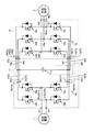
図1は、実施の形態1に係る電力変換装置を説明するための回路図である。実施の形態1に係る電力変換装置は、図1に示すように、交流電源1から供給される交流電力を直流電力に変換するコンバータ10、コンデンサセル11aを具備し、コンバータ10から供給される直流電力を蓄積するコンデンサユニット11および、コンデンサユニット11が蓄積した直流電力を交流電力に変換して交流負荷2に供給するインバータ12を有して構成される。
FIG. 1 is a circuit diagram for explaining the power conversion device according to the first embodiment. As shown in FIG. 1, the power conversion apparatus according to
コンバータ10は、スイッチング素子10a,10bで構成される上アーム(U相:10a、V相:10b)と、スイッチング素子10c,10dで構成される下アーム(U相:10c、V相:10d)とがそれぞれ直列に接続された回路部(以下「レグ」という)を有している。すなわち、コンバータ10は、U相およびV相からなる2組のレグを有する単相ブリッジ回路を構成している。
The
コンバータ10は、スイッチング素子10a,10b,10c,10dをスイッチング制御する際にパルス幅を可変する変調制御(Pulse Width Moduration:以下「PWM制御」という)を行うことで入力された交流電圧を所望の直流電圧に変換して出力する。
The
コンバータ10の出力端には、直流電源となるコンデンサユニット11が並列に接続されるとともに、コンデンサユニット11の直流電圧を入力とし、任意電圧および任意周波数の交流電圧に変換し出力するインバータ12が接続される。
A
インバータ12は、スイッチング素子12a,12b,12cで構成される上アーム(U相:12a、V相:12b、W相:12c)と、スイッチング素子12d,12e,12fで構成される下アーム(U相:12d、V相:12e、W相:12f)がそれぞれ直列に接続されたレグを有している。すなわち、インバータ12は、U相、V相およびW相からなる3組のレグを有する3相ブリッジ回路を構成している。
The
インバータ12は、スイッチング素子12a,12b,12c,12d,12e,12fをPWM制御することで入力された直流電圧を所望の交流電圧に変換して出力する。
The
つぎに、実施の形態1に係る電力変換装置の要部の構成について、図2から図4の各図面を参照して説明する。
Next, the configuration of the main part of the power conversion device according to
図2は、実施の形態1に係る電力変換装置の構成区分を図1の回路図上に示した図である。実施の形態1に係る電力変換装置は、図2に示すように、交流電力を直流電力に変換するコンバータ10と、コンバータ10が変換した直流電力を交流電力に変換するインバータ12とがシリーズに接続されたコンバータインバータユニット(以下「CIユニット」と略記する)14を構成する。CIユニット14は、コンバータ10における交流端であり、交流電源1との電気的接続端を成し、交流電源1との間で交流電力を授受する第1の入出力端子U1,V1、コンバータ10におけるコンデンサユニット11の正極側との電気的接続端を成す正極側コンデンサ接続端子PCT1,PCT2および、コンバータ10におけるコンデンサユニット11の負極側との電気的接続端を成す負極側コンデンサ接続端子NCT1,NCT2、ならびに、インバータ12における交流端であり、交流負荷2との電気的接続端を成し、交流負荷2との間で交流電力を授受する第2の入出力端子U2,V2,W2、インバータ12におけるコンデンサユニット11の正極側との電気的接続端を成す正極側コンデンサ接続端子PIT1,PIT2,PIT3および、インバータ12におけるコンデンサユニット11の負極側との電気的接続端を成すNIT1,NIT2,NIT3を具備する。
FIG. 2 is a diagram showing, on the circuit diagram of FIG. 1, the structural sections of the power conversion device according to the first embodiment. As shown in FIG. 2, the power conversion device according to the first embodiment includes a
正極側コンデンサ接続端子PCT1,PCT2は高電位側の端子であり、正極側コンデンサ接続端子PCT1は上アーム側にあるスイッチング素子10aから引き出され、正極側コンデンサ接続端子PCT2は上アーム側にあるスイッチング素子10bから引き出されている。また、負極側コンデンサ接続端子NCT1,NCT2は低電位側の端子であり、負極側コンデンサ接続端子NCT1は下アーム側にあるスイッチング素子10cから引き出され、負極側コンデンサ接続端子NCT2は下アーム側にあるスイッチング素子10dから引き出されている。
The positive side capacitor connection terminals PCT1 and PCT2 are terminals on the high potential side, the positive side capacitor connection terminal PCT1 is drawn from the
インバータ12側においても同様に構成される。すなわち、正極側コンデンサ接続端子PIT1,PIT2,PIT3は高電位側の端子であり、正極側コンデンサ接続端子PIT1は上アーム側に位置するスイッチング素子12aから引き出され、正極側コンデンサ接続端子PIT2は上アーム側に位置するスイッチング素子12bから引き出され、正極側コンデンサ接続端子PIT3は上アーム側に位置するスイッチング素子12cから引き出されている。また、負極側コンデンサ接続端子NIT1,NIT2,NIT3は低電位側の端子であり、負極側コンデンサ接続端子NIT1は下アーム側に位置するスイッチング素子12dから引き出され、負極側コンデンサ接続端子NIT2は下アーム側に位置するスイッチング素子12eから引き出され、負極側コンデンサ接続端子NIT3は下アーム側に位置するスイッチング素子12fから引き出されている。
The
コンデンサユニット11では、コンデンサセル11aの正極端とコンバータ10の正極側コンデンサ接続端子PCT1,PCT2とを電気的に接続するための接続導体PC1,PC2が引き出されている。接続導体PC1は正極側コンデンサ接続端子PCT1に接続するための導体であり、接続導体PC2は正極側コンデンサ接続端子PCT2に接続するための導体である。コンデンサセル11aの負極側においても同様であり、コンデンサセル11aの負極端とコンバータ10の負極側コンデンサ接続端子NCT1,NCT2とを電気的に接続するための接続導体NC1,NC2が引き出されている。接続導体NC1は負極側コンデンサ接続端子NCT1に接続するための導体であり、接続導体NC2は負極側コンデンサ接続端子NCT2に接続するための導体である。
In the
また、コンデンサユニット11では、コンデンサセル11aの正極端とインバータ12の正極側コンデンサ接続端子PIT1,PIT2,PIT3とを電気的に接続するための接続導体PI1,PI2,PI3が引き出されている。接続導体PI1は正極側コンデンサ接続端子PIT1に接続するための導体であり、接続導体PI2は正極側コンデンサ接続端子PIT2に接続するための導体であり、接続導体PI3は正極側コンデンサ接続端子PIT3に接続するための導体である。コンデンサセル11aの負極側においても同様であり、コンデンサセル11aの負極端とインバータ12の負極側コンデンサ接続端子NIT1,NIT2,NIT3とを電気的に接続するための接続導体NI1,NI2,NI3が引き出されている。接続導体NI1は負極側コンデンサ接続端子NIT1に接続するための導体であり、接続導体NI2は負極側コンデンサ接続端子NIT2に接続するための導体であり、接続導体NI3は負極側コンデンサ接続端子NIT3に接続するための導体である。
In the
図3は、実施の形態1に係るコンバータモジュールおよびインバータモジュールの配置例を示す平面図である。実施の形態1では、図3に示すように、後述する冷却器ベース部15bの半導体素子取付面15c上に、インバータモジュール12U,12V,12Wが、12U,12V,12Wの順序で整列して配置され、また、コンバータモジュール10A,10B,10C,10Dが、10A,10C,10D,10Bの順序で整列して配置されている。
FIG. 3 is a plan view showing an arrangement example of the converter module and the inverter module according to the first embodiment. In the first embodiment, as shown in FIG. 3,
ここで、インバータモジュール12U,12V,12Wは、1モジュール内に2つのスイッチング素子と2つのダイオードを搭載した2素子入りのモジュール(以下「2in1モジュール」という)である。図2の構成に照らして具体的に説明すると、インバータモジュール12Uでは、U相上アームのスイッチング素子12aとU相下アームのスイッチング素子12dとが1つのモジュール内に封止されている。以下同様に、インバータモジュール12Vでは、V相上アームのスイッチング素子12bとV相下アームのスイッチング素子12eとが1つのモジュール内に封止され、インバータモジュール12Wでは、W相上アームのスイッチング素子12cとW相下アームのスイッチング素子12fとがモジュール内に封止されている。
Here, the
一方、コンバータモジュール10A,10B,10C,10Dは、1モジュール内に1つのスイッチング素子と1つのダイオードを搭載した1素子入りのモジュール(以下「1in1モジュール」という)である。図2の構成に照らして説明すると、コンバータモジュール10Aには、U相上アームのスイッチング素子10aが封止され、コンバータモジュール10Bには、V相上アームのスイッチング素子10bが封止され、コンバータモジュール10Cには、U相下アームのスイッチング素子10cが封止され、コンバータモジュール10Dでは、V相下アームのスイッチング素子10dが封止されている。
On the other hand,
コンバータモジュール10Aには、図2の回路図にも示している正極側コンデンサ接続端子PCT1および接続端子U1aが設けられている。以下同様に、コンバータモジュール10Bには正極側コンデンサ接続端子PCT2および接続端子V1bが設けられ、コンバータモジュール10Cには負極側コンデンサ接続端子NCT1および接続端子U1cが設けられ、コンバータモジュール10Dには負極側コンデンサ接続端子NCT2および接続端子V1dが設けられている。
The
また、インバータモジュール12Uには、図2の回路図にも示している正極側コンデンサ接続端子PIT1、負極側コンデンサ接続端子NIT1および接続端子U2aが設けられている。以下同様に、インバータモジュール12Vには、正極側コンデンサ接続端子PIT2、負極側コンデンサ接続端子NIT2および接続端子V2aが設けられ、インバータモジュール12Wには、正極側コンデンサ接続端子PIT3、負極側コンデンサ接続端子NIT3および接続端子W2aが設けられている。
Further, the
コンバータモジュール10A,10B,10C,10Dおよびインバータモジュール12U,12V,12Wにおいて、正極側コンデンサ接続端子PIT1,PIT2,PIT3には、コンデンサユニット11から引き出された接続導体PI1,PI2,PI3が直に接続され、正極側コンデンサ接続端子PCT1,PCT2には、コンデンサユニット11から引き出された接続導体PC1,PC2が直に接続され、負極側コンデンサ接続端子NIT1,NIT2,NIT3には、コンデンサユニット11から引き出された接続導体NI1,NI2,NI3が直に接続され、正極側コンデンサ接続端子NCT1,NCT2には、コンデンサユニット11から引き出された接続導体NC1,NC2が直に接続される。
In
一方、コンバータモジュール10A,10B,10C,10Dにおける接続端子U1a,V1b,U1c,V1dは、半導体素子取付面15c上に設けた図2の回路図上にも示す第1の入出力端子U1,V1に電気配線される。すなわち、接続端子U1a,V1b,U1c,V1dは、交流電源1に直に接続される端子ではなく、交流電源1との接続は、第1の入出力端子U1,V1を介して行われる。
On the other hand, the connection terminals U1a, V1b, U1c, V1d in the
インバータモジュール12U,12V,12Wにおいても同様であり、インバータモジュール12U,12V,12Wにおける接続端子U2a,V2a,W2aは、半導体素子取付面15c上に設けた図2の回路図上にも示す第2の入出力端子U2,V2,W2に電気配線され、交流負荷2との接続は、第2の入出力端子U2,V2,W2を介して行われる。
The same applies to the
なお、図3の構成では、インバータモジュール12U,12V,12Wを2in1モジュールとして構成し、コンバータモジュール10A,10B,10C,10Dを1in1モジュールとして構成しているが、これらの構成に限定されるものではない。例えば、コンバータ10において、スイッチング素子10a,10c同士およびスイッチング素子10b,10d同士のそれぞれを1つのモジュール内に封止して2in1モジュールとして構成してもよいし、逆に、スイッチング素子12a,12b,12c,12d,12e,12fのそれぞれを1in1モジュールとして構成してもよい。また、小容量の電力変換装置であれば、スイッチング素子10a,10b,10c,10dの全てを1つのモジュール内に封止して4in1モジュールとして構成してもよいし、スイッチング素子12a,12b,12c,12d,12e,12fの全てを1つのモジュール内に封止して6in1モジュールとして構成してもよい。
In the configuration of FIG. 3, the
また、図3では、コンバータモジュール10A,10B,10C,10Dと、インバータモジュール12U,12V,12Wと、を同一基板である冷却器ベース部15bの半導体素子取付面15cに搭載しているが、コンデンサユニット11から引き出した第1の導体16aが、コンバータモジュールおよびインバータモジュールの正極側コンデンサ接続端子に接続され、且つ、コンデンサユニットから引き出した第2の導体16bが、コンバータモジュールおよびインバータモジュールの負極側コンデンサ接続端子に接続される構成である限りにおいて、異なる基板に搭載されていてもよい。
In FIG. 3, the
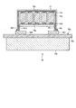
図4は、実施の形態1に係るコンデンサユニットの構造例を示す断面図である。なお、図4では、図3に示すコンバータモジュールおよびインバータモジュールの配置例において、コンバータモジュール10Aおよびインバータモジュール12Uを含む断面形状を示している。また、図4では、コンデンサユニット11を接続するコンバータモジュール10Aおよびインバータモジュール12Uを搭載し、コンバータモジュール10Aおよびインバータモジュール12Uを冷却するための冷却器15の構成を併せて示している。
FIG. 4 is a cross-sectional view showing a structural example of the capacitor unit according to the first embodiment. FIG. 4 shows a cross-sectional shape including the
第1の構造例に係るコンデンサユニット11では、図示のように5つのコンデンサセル11aが整列して配置され、コンデンサセル11aの一方の電極を成す正極端子11b同士が、コンデンサユニット11の内部にて、板状導体である第1の導体16aによって電気的に接続されると共に、コンデンサセル11aの他方の電極を成す負極端子11c同士が、同じくコンデンサユニット11の内部にて、板状導体である第2の導体16bによって電気的に接続されている。
In the
冷却器15は、冷却器ベース部15bおよび冷却器ベース部15bに設けられる冷却器放熱部15aを備える。CIユニット14に具備されるスイッチング素子10a,12aは、冷却器ベース部15bの半導体素子取付面15cに取り付けられている。半導体素子取付面15cに取り付けられたスイッチング素子10a,12aは、冷却器放熱部15aを通過する冷却風によって冷却される。
The cooler 15 includes a
第1の導体16aは、コンバータモジュール10A側において、コンデンサユニット11の外部に引き出されて上述した接続導体PC1を構成し、また、インバータモジュール12U側において、コンデンサユニット11の外部に引き出されて上述した接続導体PI1を構成する。
The
同様に、第2の導体16bは、コンバータモジュール10A側において、コンデンサユニット11の外部に引き出されて上述した接続導体NC1を構成し、また、インバータモジュール12U側において、コンデンサユニット11の外部に引き出されて上述した接続導体NI1を構成する。なお、図4では、第1の導体16aと第2の導体16bとが積層構造となるように配置しているが、このような構成の場合、第1の導体16aと第2の導体16bとの間に絶縁シートが挿入されて電気的な絶縁が施されることは言うまでもない。
Similarly, the
上述したように、接続導体PC1は、コンバータモジュール10Aの正極側コンデンサ接続端子PCT1に直に接続され、接続導体PI1は、インバータモジュール12Uの正極側コンデンサ接続端子PIT1に直に接続される。また、接続導体NI1は、インバータモジュール12Uの負極側コンデンサ接続端子NIT1に、公知の端子接続構造にて電気的に接続される。なお、接続導体NC1は、コンバータモジュール10Aの端子には電気的に接続されず、コンバータモジュール10Cの負極側コンデンサ接続端子NCT1に電気的に接続されることは上述の通りである。
As described above, the connection conductor PC1 is directly connected to the positive capacitor connection terminal PCT1 of the
図5は、実施の形態1に係るコンデンサユニットの図4とは異なる構造例を示す断面図である。図4に示す第1の構造例に係るコンデンサユニット11では、コンデンサセル11aの上部に負極端子11cを配し、下部に正極端子11bを配していたが、図5に示す第2の構造例に係るコンデンサユニット11では、コンデンサセル11aの内部を貫通する導体11dによって負極端子11cと第2の導体16bとを電気的に接続している。この構成により、第1の導体16aと第2の導体16bとがコンデンサユニット11の内部および外部の双方において並行して配設される。ここで、スイッチング素子がスイッチング動作するときに第1の導体16aに流れる電流と、第2の導体16bに流れる電流とは大きさが同じで通流方向が逆となるため、並行して配設される部分が長くなる程、インダクタンス低減の効果が大きくなる。このため、第2の構造例に係るコンデンサユニット11は、第1の構造例に係るコンデンサユニット11よりも配線インダクタンスが小さくなる。
5 is a cross-sectional view showing a structural example different from FIG. 4 of the capacitor unit according to the first embodiment. In the
なお、図4および図5の構成では、第1の導体16aと第2の導体16bとによって、コンデンサユニット11を支える構成であるが、コンデンサユニット11の重量がある場合、または、第1の導体16aおよび第2の導体16bの厚みを薄くするなどして軽量化を図る場合において、第1の導体16aおよび第2の導体16bのみでは、コンデンサユニット11を支えられない場合には、コンデンサユニット11を収納する構造物によって固定し、また、コンデンサユニット11の側部に設けた支えフレームによって、固定する構成を採用すればよい。
4 and 5, the
つぎに、実施の形態1に係る電力変換装置が固有に有する効果について説明する。
Next, effects inherent in the power conversion device according to
まず、実施の形態1に係る電力変換装置における端子接続構造では、CI構成の電力変換装置において、コンデンサユニット11から引き出した第1の導体16aをコンバータモジュールに直に接続し、且つ、コンデンサユニットから引き出した第2の導体16bをインバータモジュールに直に接続する構成としているので、従来よりも配線距離を短くでき、低インダクタンスの配線を行うことが可能となる。
First, in the terminal connection structure in the power conversion device according to the first embodiment, in the power conversion device having the CI configuration, the
また、実施の形態1に係る端子接続構造では、1つのコンデンサユニットで、CI構成の電力変換装置を単一のコンデンサユニットで構成でき、コンバータおよびインバータのそれぞれでコンデンサユニットもしくはコンデンサを設ける必要がなくなるので、コンバータ側に設けた第1のコンデンサと、インバータ側に設けた第2のコンデンサとの間の共振現象の発生を抑止することが可能となる。また、第1のコンデンサと第2のコンデンサとの間、すなわち電力変換装置の直流区間で行き来する可能性のある電流を小さくできるので、直流区間での損失を低減することが可能となる。また、従来よりも、コンデンサの数量を減らすことができ、第1のコンデンサと第2のコンデンサとの間の配線も不要になるので、製造コストの低減が可能となる。 In the terminal connection structure according to the first embodiment, the CI power converter can be configured with a single capacitor unit with one capacitor unit, and it is not necessary to provide a capacitor unit or a capacitor for each of the converter and the inverter. Therefore, it is possible to suppress the occurrence of a resonance phenomenon between the first capacitor provided on the converter side and the second capacitor provided on the inverter side. In addition, since the current that can travel between the first capacitor and the second capacitor, that is, in the DC section of the power converter, can be reduced, loss in the DC section can be reduced. Further, the number of capacitors can be reduced as compared with the conventional case, and the wiring between the first capacitor and the second capacitor is not necessary, so that the manufacturing cost can be reduced.
また、最近の電力変換装置では、用途に応じて、炭化珪素(SiC)を素材とする半導体素子(SiC素子)の使用が検討されている。SiC素子は、珪素(Si)を素材とする半導体素子と比較して、熱伝達率が大きい、高温での動作が可能、高速スイッチングが可能といった優れた特性を有している。その一方で、SiC素子は、高速スイッチングが可能ゆえに電力変換装置の内部の配線に通流するスイッチング電流の時間変化率が大きいため、配線に発生するサージ電圧が大きく、電力変換装置の内部の部品に加わるサージ電圧が大きくなる。よって、SiC素子を用いる場合には、低インダクタンスが求められるが、実施の形態1に係る端子接続構造は低インダクタンスを実現でき、電力変換装置の内部の部品に加わるサージ電圧を小さくすることができるので、SiC素子を適用した電力変換装置に特に有用である。 Further, in recent power converters, use of a semiconductor element (SiC element) made of silicon carbide (SiC) as a material has been studied depending on the application. The SiC element has excellent characteristics such as a large heat transfer coefficient, operation at a high temperature, and high-speed switching as compared with a semiconductor element made of silicon (Si). On the other hand, since the SiC element is capable of high-speed switching, the time change rate of the switching current flowing through the wiring inside the power conversion device is large, so the surge voltage generated in the wiring is large, and the components inside the power conversion device The surge voltage applied to becomes larger. Therefore, when using the SiC element, low inductance is required, but the terminal connection structure according to the first embodiment can realize low inductance, and the surge voltage applied to the components inside the power converter can be reduced. Therefore, it is particularly useful for a power conversion device to which a SiC element is applied.
また、SiC素子は、高温での動作が可能であるため、冷却器15を小さくすることができる。ここで、冷却器15のサイズを小さくできれば、冷却器15の半導体素子取付面15cに搭載されるコンバータモジュールとインバータモジュールとの間の距離が小さくなるので、接続配線の低インダクタンス化には好ましい方向に作用する。
Moreover, since the SiC element can operate at a high temperature, the cooler 15 can be made small. Here, if the size of the cooler 15 can be reduced, the distance between the converter module mounted on the semiconductor
なお、SiCは、Siよりもバンドギャップが大きいという特性を捉えて、ワイドバンドギャップ半導体と称される半導体の一例である(これに対し、Siは、ナローバンドギャップ半導体と称される)。このSiC以外にも、例えば窒化ガリウム系材料または、ダイヤモンドを用いて形成される半導体もワイドバンドギャップ半導体に属しており、それらの特性も炭化珪素に類似した点が多い。したがって、SiC以外の他のワイドバンドギャップ半導体素子を用いる構成も、本発明の要旨を成すものである。 Note that SiC is an example of a semiconductor referred to as a wide bandgap semiconductor, taking the characteristic that the bandgap is larger than that of Si (in contrast, Si is referred to as a narrow bandgap semiconductor). In addition to this SiC, for example, a semiconductor formed using a gallium nitride-based material or diamond belongs to a wide band gap semiconductor, and their characteristics are also similar to silicon carbide. Accordingly, a configuration using a wide band gap semiconductor element other than SiC also forms the gist of the present invention.
実施の形態2.
実施の形態2では、コンバータモジュールおよびインバータモジュールに係る配置のバリエーションについて説明する。図6は、実施の形態2に係るコンバータモジュールおよびインバータモジュールの配置例を示す平面図である。図3では、コンバータモジュールにおける接続端子U1a,U1c,V1b,V1dと、インバータモジュールにおける接続端子U2a,V2a,W2aと、が搭載面において向かい合うようにコンバータモジュール10A,10B,10C,10Dおよびインバータモジュール12U,12V,12Wを配置していたが、図6では、コンバータモジュールにおける接続端子U1a,U1c,V1b,V1dと、インバータモジュールにおける接続端子U2a,V2a,W2aと、が基板の外方を向くように、別言すれば、コンバータモジュールにおける正極側コンデンサ接続端子PCT1,PCT2および負極側コンデンサ接続端子NCT1,NCT2と、インバータモジュールにおける正極側コンデンサ接続端子PIT1,PIT2,PIT3および負極側コンデンサ接続端子NIT1,NIT2,NIT3と、が搭載面において向かい合うようにコンバータモジュール10A,10B,10C,10Dおよびインバータモジュール12U,12V,12Wを配置している。
In the second embodiment, variations of the arrangement relating to the converter module and the inverter module will be described. FIG. 6 is a plan view showing an arrangement example of the converter module and the inverter module according to the second embodiment. In FIG. 3, the
図6の構成の場合、第1の入出力端子U1,V1と、コンバータモジュール10A,10B,10C,10Dにおける接続端子U1a,V1b,U1c,V1dとの間の距離が図3に比して短くなるので、配線部材の長さの短縮化が可能となる。
In the case of the configuration of FIG. 6, the distance between the first input / output terminals U1, V1 and the connection terminals U1a, V1b, U1c, V1d in the
また、インバータモジュール12U,12V,12Wにおいても同様であり、第2の入出力端子U2,V2,W2と、インバータモジュール12U,12V,12Wとの間の距離が図3に比して短くなるので、配線部材の長さの短縮化が可能となる。
The same applies to the
また、図6の構成の場合、コンバータモジュール10A,10B,10C,10Dにおける正極側コンデンサ接続端子PCT1,PCT2および負極側コンデンサ接続端子NCT1,NCT2と、インバータモジュール12U,12V,12Wにおける正極側コンデンサ接続端子PIT1,PIT2,PIT3および負極側コンデンサ接続端子NIT1,NIT2,NIT3との間の距離が短くなるので、コンデンサセル11aの容量が小さく、コンデンサユニット11のサイズが小さい場合には、コンデンサユニット11から引き出す第1の導体16aおよび第2の導体16bの長さを短くできるので、配線の低インダクタンス化には有効に作用する。逆に、コンデンサセル11aの容量が大きく、コンデンサユニット11のサイズが大きい場合には、図3の構成の方が有利になる場合がある。
In the case of the configuration of FIG. 6, the positive side capacitor connection terminals PCT1 and PCT2 and the negative side capacitor connection terminals NCT1 and NCT2 in the
なお、図3では、コンバータモジュールにおける接続端子U1a,U1c,V1b,V1dと、インバータモジュールにおける接続端子U2a,V2a,W2aと、が搭載面において向かい合うようにコンバータモジュール10A,10B,10C,10Dおよびインバータモジュール12U,12V,12Wを配置し、図6では、コンバータモジュールにおける正極側コンデンサ接続端子PCT1,PCT2および負極側コンデンサ接続端子NCT1,NCT2と、インバータモジュールにおける正極側コンデンサ接続端子PIT1,PIT3,PIT3および負極側コンデンサ接続端子NIT1,NIT2,NIT3と、が搭載面において向かい合うようにコンバータモジュール10A,10B,10C,10Dおよびインバータモジュール12U,12V,12Wを配置しているが、図3および図6の何れの配置においても何れか一方を反転させて配置してもよい。
In FIG. 3, the
すなわち、コンバータモジュールにおける正極側コンデンサ接続端子PCT1,PCT2および負極側コンデンサ接続端子NCT1,NCT2と、インバータモジュールにおける接続端子U2a,V2a,W2aと、が搭載面において向かい合うようにコンバータモジュール10A,10B,10C,10Dおよびインバータモジュール12U,12V,12Wを配置してもよいし、また、この配置とは逆に、コンバータモジュールにおける接続端子U1a,U1c,V1b,V1dと、インバータモジュールにおける正極側コンデンサ接続端子PIT1,PIT2,PIT3および負極側コンデンサ接続端子NIT1,NIT2,NIT3と、が搭載面において向かい合うようにコンバータモジュール10A,10B,10C,10Dおよびインバータモジュール12U,12V,12Wを配置してもよい。
That is,
以上、実施の形態1,2に係る電力変換装置および、その端子接続構造について説明してきたが、上述した内容は一例を示すものであり、本発明の要旨を逸脱しない範囲で、一部を省略する等、変更して構成することも可能であることは言うまでもない。
As mentioned above, although the power converter device which concerns on
1 交流電源、2 交流負荷、10 コンバータ、10A,10B,10C,10D コンバータモジュール、10a,10b,10c,10d,12a,12b,12c,12d,12e,12f スイッチング素子、11 コンデンサユニット、11a コンデンサセル、11b 正極端子、11c 負極端子、11d 導体、12 インバータ、12U,12V,12W インバータモジュール、14 CIユニット、15 冷却器、15a 冷却器放熱部、15b 冷却器ベース部、15c 半導体素子取付面、16a 第1の導体、16b 第2の導体、PC1,PC2,NC1,NC2,PI1,PI2,PI3,NI1,NI2,NI3 接続導体、PCT1,PCT2,PIT1,PIT2,PIT3 正極側コンデンサ接続端子、NCT1,NCT2,NIT1,NIT2,NIT3 負極側コンデンサ接続端子、U1,V1 第1の入出力端子、U2,V2,W2 第2の入出力端子、U1a,V1b,U1c,V1d,U2a,V2a,W2a 接続端子。
1 AC power supply, 2 AC load, 10 converter, 10A, 10B, 10C, 10D converter module, 10a, 10b, 10c, 10d, 12a, 12b, 12c, 12d, 12e, 12f switching element, 11 capacitor unit,
上述した課題を解決し、目的を達成するために、本発明は、コンバータモジュールを具備し、交流電力を直流電力に変換するコンバータと、インバータモジュールを具備し、前記コンバータが変換した直流電力を交流電力に変換するインバータとがシリーズに接続されてコンバータインバータユニットを構成する電力変換装置であって、前記コンバータが変換した直流電力を蓄積するコンデンサセルを具備し、前記コンバータと前記インバータとの間に設けられるコンデンサユニットと、前記コンデンサユニットの内部にて前記コンデンサセルの一方の電極に電気的に接続され、端部がそれぞれ前記コンデンサユニットの外部に位置して、前記コンバータモジュールの正極側コンデンサ接続端子および前記インバータモジュールの正極側コンデンサ接続端子に接続される第1の導体と、前記コンデンサユニットの内部にて前記コンデンサセルの他方の電極に電気的に接続され、端部がそれぞれ前記コンデンサユニットの外部に位置して、前記コンバータモジュールの負極側コンデンサ接続端子および前記インバータモジュールの負極側コンデンサ接続端子に接続される第2の導体と、を備え、前記コンバータモジュールまたは前記インバータモジュール内に設けられたスイッチング素子がスイッチング動作をするときに、前記第1の導体の前記端部または前記第2の導体の前記端部を介して直流電流が流れることを特徴とする。 In order to solve the above-described problems and achieve the object, the present invention includes a converter module, a converter that converts AC power into DC power, and an inverter module, and the DC power converted by the converter is converted into AC. a power conversion device is an inverter for converting the power to configure the connected converter inverter unit in series, comprising a capacitor cell before Symbol converter accumulates the DC power converted, between the converter and the inverter A capacitor unit provided in the capacitor unit, and electrically connected to one electrode of the capacitor cell inside the capacitor unit, each of which is located outside the capacitor unit and connected to the positive side capacitor of the converter module Terminal and the positive side of the inverter module A first conductor that is connected to the capacitors connecting terminal, wherein at the inside of the capacitor unit is electrically connected to the other electrode of the capacitor cell, and the end is positioned outside of each of the capacitor unit, wherein and a second conductor which is connected to the negative capacitor connection terminal of the negative electrode side capacitor connecting terminal and the inverter module of the converter module, the converter module or a switching element provided in the inverter module switching operation In this case, a direct current flows through the end portion of the first conductor or the end portion of the second conductor .
Claims (8)
前記コンバータと前記インバータとの間には、前記コンバータが変換した直流電力を蓄積するコンデンサセルを具備するコンデンサユニットが設けられ、
前記コンデンサセルの一方の電極に電気的に接続された第1の導体と前記コンデンサセルの他方の電極に電気的に接続された第2の導体とが、前記コンデンサユニットから引き出され、
前記第1の導体は前記コンバータモジュールの正極側コンデンサ接続端子および前記インバータモジュールの正極側コンデンサ接続端子に直に接続され、前記第2の導体は前記コンバータモジュールの負極側コンデンサ接続端子および前記インバータモジュールの負極側コンデンサ接続端子に直に接続される
ことを特徴とする電力変換装置。 A converter module having a converter module for converting AC power into DC power and an inverter module having an inverter module for converting DC power converted by the converter into AC power are connected in series to form a converter inverter unit. A power converter,
Between the converter and the inverter, a capacitor unit including a capacitor cell that stores DC power converted by the converter is provided,
A first conductor electrically connected to one electrode of the capacitor cell and a second conductor electrically connected to the other electrode of the capacitor cell are drawn from the capacitor unit;
The first conductor is directly connected to the positive side capacitor connection terminal of the converter module and the positive side capacitor connection terminal of the inverter module, and the second conductor is the negative side capacitor connection terminal of the converter module and the inverter module. A power conversion device characterized in that it is directly connected to the negative electrode side capacitor connection terminal.
Priority Applications (1)
| Application Number | Priority Date | Filing Date | Title |
|---|---|---|---|
| JP2017112783A JP6884645B2 (en) | 2017-06-07 | 2017-06-07 | Power converter |
Applications Claiming Priority (1)
| Application Number | Priority Date | Filing Date | Title |
|---|---|---|---|
| JP2017112783A JP6884645B2 (en) | 2017-06-07 | 2017-06-07 | Power converter |
Related Parent Applications (1)
| Application Number | Title | Priority Date | Filing Date |
|---|---|---|---|
| JP2016558830A Division JP6174824B2 (en) | 2015-04-20 | 2015-04-20 | Power converter |
Publications (2)
| Publication Number | Publication Date |
|---|---|
| JP2017184613A true JP2017184613A (en) | 2017-10-05 |
| JP6884645B2 JP6884645B2 (en) | 2021-06-09 |
Family
ID=60006621
Family Applications (1)
| Application Number | Title | Priority Date | Filing Date |
|---|---|---|---|
| JP2017112783A Active JP6884645B2 (en) | 2017-06-07 | 2017-06-07 | Power converter |
Country Status (1)
| Country | Link |
|---|---|
| JP (1) | JP6884645B2 (en) |
Cited By (1)
| Publication number | Priority date | Publication date | Assignee | Title |
|---|---|---|---|---|
| WO2019146179A1 (en) * | 2018-01-26 | 2019-08-01 | 株式会社日立製作所 | Power conversion device and electric railroad vehicle equipped with power conversion device |
Citations (10)
| Publication number | Priority date | Publication date | Assignee | Title |
|---|---|---|---|---|
| JPS4986852A (en) * | 1972-12-26 | 1974-08-20 | ||
| JPS5412049U (en) * | 1977-06-27 | 1979-01-26 | ||
| JPS5421567A (en) * | 1977-07-19 | 1979-02-17 | Nitsuko Ltd | Wound type flat electrolytic capacitor |
| JPS5527949U (en) * | 1978-08-10 | 1980-02-22 | ||
| JPS5696831A (en) * | 1979-12-30 | 1981-08-05 | Nippon Chemical Condenser Kk | Electrolytic condenser |
| JPS56155438U (en) * | 1980-04-19 | 1981-11-20 | ||
| JP2006262665A (en) * | 2005-03-18 | 2006-09-28 | Toyota Motor Corp | Inverter unit for vehicle |
| JP2007068294A (en) * | 2005-08-30 | 2007-03-15 | Nissan Motor Co Ltd | Power converter |
| JP2010193593A (en) * | 2009-02-17 | 2010-09-02 | Hitachi Ltd | Power converter |
| JP2011239679A (en) * | 2011-08-30 | 2011-11-24 | Hitachi Automotive Systems Ltd | Power conversion equipment |
-
2017
- 2017-06-07 JP JP2017112783A patent/JP6884645B2/en active Active
Patent Citations (10)
| Publication number | Priority date | Publication date | Assignee | Title |
|---|---|---|---|---|
| JPS4986852A (en) * | 1972-12-26 | 1974-08-20 | ||
| JPS5412049U (en) * | 1977-06-27 | 1979-01-26 | ||
| JPS5421567A (en) * | 1977-07-19 | 1979-02-17 | Nitsuko Ltd | Wound type flat electrolytic capacitor |
| JPS5527949U (en) * | 1978-08-10 | 1980-02-22 | ||
| JPS5696831A (en) * | 1979-12-30 | 1981-08-05 | Nippon Chemical Condenser Kk | Electrolytic condenser |
| JPS56155438U (en) * | 1980-04-19 | 1981-11-20 | ||
| JP2006262665A (en) * | 2005-03-18 | 2006-09-28 | Toyota Motor Corp | Inverter unit for vehicle |
| JP2007068294A (en) * | 2005-08-30 | 2007-03-15 | Nissan Motor Co Ltd | Power converter |
| JP2010193593A (en) * | 2009-02-17 | 2010-09-02 | Hitachi Ltd | Power converter |
| JP2011239679A (en) * | 2011-08-30 | 2011-11-24 | Hitachi Automotive Systems Ltd | Power conversion equipment |
Cited By (3)
| Publication number | Priority date | Publication date | Assignee | Title |
|---|---|---|---|---|
| WO2019146179A1 (en) * | 2018-01-26 | 2019-08-01 | 株式会社日立製作所 | Power conversion device and electric railroad vehicle equipped with power conversion device |
| JPWO2019146179A1 (en) * | 2018-01-26 | 2021-01-28 | 株式会社日立製作所 | Electric railroad vehicle equipped with a power converter and a power converter |
| US11211881B2 (en) | 2018-01-26 | 2021-12-28 | Hitachi, Ltd. | Power conversion device and electric railroad vehicle equipped with power conversion device |
Also Published As
| Publication number | Publication date |
|---|---|
| JP6884645B2 (en) | 2021-06-09 |
Similar Documents
| Publication | Publication Date | Title |
|---|---|---|
| US9270199B2 (en) | Power conversion apparatus with a laminated bus bar comprising an exposed heat radiating portion | |
| US10153708B2 (en) | Three-level power converter | |
| US8400775B2 (en) | Capacitor with direct DC connection to substrate | |
| JP2020505900A (en) | Semiconductor configuration | |
| US10811958B2 (en) | Water-cooling power supply module | |
| JP2022062235A (en) | Package structure for power devices | |
| US8675379B2 (en) | Power converting apparatus having improved electro-thermal characteristics | |
| JP2013198170A (en) | Power conversion device | |
| CN114649279A (en) | Wide bandgap semiconductor double-sided heat dissipation module packaging structure based on conductive metal strip | |
| WO2008001413A1 (en) | Power converter | |
| JP6174824B2 (en) | Power converter | |
| JP2017184613A (en) | Power conversion device | |
| CN104518681A (en) | Electric power conversion device | |
| JPWO2018109884A1 (en) | Power converter | |
| JP2007325387A (en) | Power conversion device | |
| US10855196B2 (en) | Semiconductor device | |
| JP2002171768A (en) | Power converter | |
| JPH02174564A (en) | Main circuitry for inverter | |
| JP2002125381A (en) | Power converter | |
| KR102063726B1 (en) | Motor integrated inverter package and All-in-one inverter applied to the same | |
| CN210137281U (en) | Power module of DC-DC converter | |
| JP7069885B2 (en) | Semiconductor device | |
| WO2018130408A1 (en) | Power module with optimized pin layout | |
| JP2002209391A (en) | Semiconductor power converter | |
| JP2013240151A (en) | Power conversion device |
Legal Events
| Date | Code | Title | Description |
|---|---|---|---|
| A521 | Request for written amendment filed |
Free format text: JAPANESE INTERMEDIATE CODE: A523 Effective date: 20170712 |
|
| A621 | Written request for application examination |
Free format text: JAPANESE INTERMEDIATE CODE: A621 Effective date: 20170712 |
|
| A977 | Report on retrieval |
Free format text: JAPANESE INTERMEDIATE CODE: A971007 Effective date: 20180713 |
|
| A131 | Notification of reasons for refusal |
Free format text: JAPANESE INTERMEDIATE CODE: A131 Effective date: 20180731 |
|
| A601 | Written request for extension of time |
Free format text: JAPANESE INTERMEDIATE CODE: A601 Effective date: 20180925 |
|
| A521 | Request for written amendment filed |
Free format text: JAPANESE INTERMEDIATE CODE: A523 Effective date: 20181119 |
|
| A131 | Notification of reasons for refusal |
Free format text: JAPANESE INTERMEDIATE CODE: A131 Effective date: 20190507 |
|
| A02 | Decision of refusal |
Free format text: JAPANESE INTERMEDIATE CODE: A02 Effective date: 20200107 |
|
| A521 | Request for written amendment filed |
Free format text: JAPANESE INTERMEDIATE CODE: A523 Effective date: 20200330 |
|
| C60 | Trial request (containing other claim documents, opposition documents) |
Free format text: JAPANESE INTERMEDIATE CODE: C60 Effective date: 20200330 |
|
| A911 | Transfer to examiner for re-examination before appeal (zenchi) |
Free format text: JAPANESE INTERMEDIATE CODE: A911 Effective date: 20200409 |
|
| C21 | Notice of transfer of a case for reconsideration by examiners before appeal proceedings |
Free format text: JAPANESE INTERMEDIATE CODE: C21 Effective date: 20200414 |
|
| A912 | Re-examination (zenchi) completed and case transferred to appeal board |
Free format text: JAPANESE INTERMEDIATE CODE: A912 Effective date: 20200717 |
|
| C211 | Notice of termination of reconsideration by examiners before appeal proceedings |
Free format text: JAPANESE INTERMEDIATE CODE: C211 Effective date: 20200721 |
|
| C22 | Notice of designation (change) of administrative judge |
Free format text: JAPANESE INTERMEDIATE CODE: C22 Effective date: 20200923 |
|
| C13 | Notice of reasons for refusal |
Free format text: JAPANESE INTERMEDIATE CODE: C13 Effective date: 20201201 |
|
| A521 | Request for written amendment filed |
Free format text: JAPANESE INTERMEDIATE CODE: A523 Effective date: 20210129 |
|
| C13 | Notice of reasons for refusal |
Free format text: JAPANESE INTERMEDIATE CODE: C13 Effective date: 20210302 |
|
| A521 | Request for written amendment filed |
Free format text: JAPANESE INTERMEDIATE CODE: A523 Effective date: 20210310 |
|
| C302 | Record of communication |
Free format text: JAPANESE INTERMEDIATE CODE: C302 Effective date: 20210319 |
|
| C23 | Notice of termination of proceedings |
Free format text: JAPANESE INTERMEDIATE CODE: C23 Effective date: 20210330 |
|
| C03 | Trial/appeal decision taken |
Free format text: JAPANESE INTERMEDIATE CODE: C03 Effective date: 20210511 |
|
| C30A | Notification sent |
Free format text: JAPANESE INTERMEDIATE CODE: C3012 Effective date: 20210511 |
|
| A61 | First payment of annual fees (during grant procedure) |
Free format text: JAPANESE INTERMEDIATE CODE: A61 Effective date: 20210512 |
|
| R150 | Certificate of patent or registration of utility model |
Ref document number: 6884645 Country of ref document: JP Free format text: JAPANESE INTERMEDIATE CODE: R150 |