JP2017183960A - Switch control device, method and program - Google Patents
Switch control device, method and program Download PDFInfo
- Publication number
- JP2017183960A JP2017183960A JP2016067221A JP2016067221A JP2017183960A JP 2017183960 A JP2017183960 A JP 2017183960A JP 2016067221 A JP2016067221 A JP 2016067221A JP 2016067221 A JP2016067221 A JP 2016067221A JP 2017183960 A JP2017183960 A JP 2017183960A
- Authority
- JP
- Japan
- Prior art keywords
- packet
- switch
- address
- gateway
- ofs
- Prior art date
- Legal status (The legal status is an assumption and is not a legal conclusion. Google has not performed a legal analysis and makes no representation as to the accuracy of the status listed.)
- Pending
Links
Images


Abstract
Description
本発明は、パケットを転送するスイッチを制御するスイッチ制御装置、スイッチ制御方法およびスイッチ制御プログラムに関する。 The present invention relates to a switch control device, a switch control method, and a switch control program for controlling a switch that transfers a packet.
パケットを転送するスイッチを制御装置が制御するプロトコルとして、オープンフロー(OpenFlow)が知られている。 An open flow (OpenFlow) is known as a protocol in which a control device controls a switch for transferring a packet.
オープンフローでは、制御装置がスイッチにフローエントリを設定する。そして、スイッチは、受信したパケットをそのフローエントリに従って処理する。フローエントリとは、パケットをどのように処理するか(例えば、パケットをどこに転送するか等)を規定した情報である。フローエントリは、パケットのフロー毎に設定される。スイッチがパケットを受信したときに、そのパケットのフローに対応するフローエントリが存在する場合、スイッチは、そのフローエントリに従ってそのパケットを処理する。一方、受信したパケットのフローに対応するフローエントリが存在しない場合、スイッチは、そのパケットを制御装置に送信する。そして、制御装置は、そのパケットのフローに対応するフローエントリ決定し、スイッチに設定する。 In the open flow, the control device sets a flow entry in the switch. Then, the switch processes the received packet according to the flow entry. The flow entry is information that defines how to process a packet (for example, where to transfer the packet). The flow entry is set for each packet flow. When the switch receives a packet and there is a flow entry corresponding to the flow of the packet, the switch processes the packet according to the flow entry. On the other hand, when there is no flow entry corresponding to the flow of the received packet, the switch transmits the packet to the control device. Then, the control device determines a flow entry corresponding to the flow of the packet and sets it in the switch.
オープンフローにおいて、制御装置とスイッチとが送受信するメッセージの例として「パケットイン(Packet_in )」、「パケットアウト(Packet_out)」等がある。 Examples of messages transmitted and received between the control device and the switch in the open flow include “packet in (Packet_in)” and “packet out (Packet_out)”.
「パケットイン」は、スイッチから制御装置に送られるメッセージである。「パケットイン」は、対応するフローエントリが存在しなかったパケットをスイッチから制御装置に送るために用いられる。 “Packet-in” is a message sent from the switch to the control device. “Packet-in” is used to send a packet for which no corresponding flow entry exists from the switch to the control device.
「パケットアウト」は、制御装置からスイッチに送られるメッセージである。「パケットアウト」は、ポートからのパケット出力を指示するメッセージである。 “Packet out” is a message sent from the control device to the switch. “Packet out” is a message instructing packet output from the port.
なお、個々のスイッチは、それぞれ、制御装置と、専用の経路で接続される。この専用の経路は、制御チャネルと呼ばれる。制御装置は、個々のスイッチと、制御チャネルを介して通信する。 Each switch is connected to the control device through a dedicated path. This dedicated path is called a control channel. The control device communicates with individual switches via a control channel.
特許文献1には、ネットワーク上に物理的に分散配備された制御信号処理部とデータ信号処理部が連携してパケット転送処理を行う機能分散型のパケット転送処理装置に関する技術が記載されている。
本明細書では、スイッチに接続され、パケットの送信元や宛先となる装置を端末と記す。 In this specification, a device connected to a switch and serving as a packet transmission source or destination is referred to as a terminal.
オープンフローで制御されるスイッチを含むネットワークにおいて、いずれかのスイッチに接続される端末に、他の端末からのアクセスが集中する場合がある。 In a network including a switch controlled by OpenFlow, access from other terminals may concentrate on a terminal connected to any switch.
アクセスが集中する端末が接続されているスイッチでは、その端末の通信相手となる端末台数分のフローエントリの設定が必要になる。このとき、通信相手となる端末台数が多いと、そのスイッチに大量のフローエントリを設定する必要が生じる。また、そのフローエントリの数が、スイッチに設定可能なフローエントリの数を超えた場合、スイッチに設定することができないフローエントリが生じる場合もある。 In a switch to which a terminal to which access is concentrated is connected, it is necessary to set flow entries for the number of terminals that are communication partners of the terminal. At this time, if the number of terminals that are communication partners is large, a large number of flow entries need to be set in the switch. Further, when the number of flow entries exceeds the number of flow entries that can be set in the switch, there may be a flow entry that cannot be set in the switch.
図16は、1つの端末にアクセスが集中するネットワーク構成の例を示す模式図である。図16では、アクセスが集中する端末の例として、DNS(Domain Name System)サーバを例示している。また、その他の端末がパーソナルコンピュータ(以下、PCと記す。)である場合を例示している。また、以下の説明では、オープンフローにおける制御装置をOFCと記し、オープンフローにおけるスイッチをOFSと記す。 FIG. 16 is a schematic diagram illustrating an example of a network configuration in which access concentrates on one terminal. In FIG. 16, a DNS (Domain Name System) server is illustrated as an example of a terminal where access is concentrated. Further, the case where the other terminal is a personal computer (hereinafter referred to as PC) is illustrated. In the following description, the control device in the open flow is denoted as OFC, and the switch in the open flow is denoted as OFS.
図16において、パケット通信の経路を実線で示し、制御チャネルを破線で示している。#とともに記した番号は、OFSのポート番号である。OFC7は、各OFS1〜5にフローエントリを設定する。図16に示す例では、DNSサーバ20に、n台のPC10a〜10nからのアクセスが集中する。この場合、DNSサーバ20が接続されているOFS4に、n個のフローエントリを設定する必要がある。また、OFS4に、アクセスが集中する端末がm台接続されている場合には、n×m個のフローエントリをOFS4に設定する必要がある。
In FIG. 16, the packet communication path is indicated by a solid line, and the control channel is indicated by a broken line. The numbers marked with # are OFS port numbers. The OFC 7 sets flow entries in the
図17は、DNSサーバ20が接続されているOFS4に設定される各フローエントリを示す模式図である。図17では、送信元MAC(Media Access Control)アドレスと宛先MACアドレスとの組に応じたアクションを、宛先となるPC毎に示している。なお、アクションとして示した“Port#1”は、ポート#1からパケットを出力することを意味する。PCの台数がn台であれば、n個のフローエントリがOFS4に設定される。PCの台数が多いと、上述のように、OFS4に大量のフローエントリを設定する必要が生じたり、OFS4に設定することができないフローエントリが生じたりする。
FIG. 17 is a schematic diagram showing each flow entry set in the
OFS4に設定するフローエントリの数を減らすために、DNSサーバ20を複数のOFSに分散させることが考えられるが、その場合、ネットワーク設計の難易度が高くなってしまう。
In order to reduce the number of flow entries set in the
そこで、本発明は、スイッチに接続されている端末にアクセスが集中する場合であっても、そのスイッチに設定されるフローエントリの数の増加を防止することができるスイッチ制御装置、スイッチ制御方法およびスイッチ制御プログラムを提供することを目的とする。 Therefore, the present invention provides a switch control device, a switch control method, and a switch control device capable of preventing an increase in the number of flow entries set in a switch even when access is concentrated on a terminal connected to the switch. An object is to provide a switch control program.
本発明によるスイッチ制御装置は、サブネットワークに対応付けられたスイッチであるゲートウェイスイッチ、およびゲートウェイスイッチ間でパケットを中継する中継スイッチに対して、パケットに対するアクションを規定したフローエントリを設定するフローエントリ設定手段を備え、フローエントリ設定手段が、中継スイッチに対して、ゲートウェイスイッチに対応するサブネットワークのアドレスに宛先アドレスが該当しているパケットをそのゲートウェイスイッチに転送することを規定したフローエントリを、中継スイッチ以外のゲートウェイスイッチ毎に設定し、ゲートウェイスイッチからパケットを受信したときに、そのゲートウェイスイッチに対して、パケットの送信元の端末を宛先とするパケットをその端末に転送することを規定したフローエントリを設定するとともに、そのゲートウェイスイッチに対して、当該ゲートウェイスイッチ以外のゲートウェイスイッチ毎に、その端末を送信元とし、ゲートウェイスイッチに対応するサブネットワークのアドレスに宛先アドレスが該当しているパケットを中継スイッチに転送することを規定したフローエントリを設定することを特徴とする。 A switch control apparatus according to the present invention sets a flow entry that defines an action for a packet in a gateway switch that is a switch associated with a subnetwork and a relay switch that relays the packet between gateway switches. And the flow entry setting means relays a flow entry that specifies that a packet whose destination address corresponds to the address of the subnetwork corresponding to the gateway switch is forwarded to the gateway switch. Set for each gateway switch other than the switch, when a packet is received from the gateway switch, the packet destined to the terminal that sent the packet is forwarded to that terminal. In addition to setting a flow entry that specifies the destination address for the gateway switch, the destination address corresponds to the address of the sub-network corresponding to the gateway switch for each gateway switch other than the gateway switch. It is characterized by setting a flow entry that defines that a packet to be transferred to a relay switch.
また、本発明によるスイッチ制御方法は、スイッチを制御するスイッチ制御装置が、サブネットワークに対応付けられたスイッチであるゲートウェイスイッチ間でパケットを中継する中継スイッチに対して、ゲートウェイスイッチに対応するサブネットワークのアドレスに宛先アドレスが該当しているパケットをそのゲートウェイスイッチに転送することを規定したフローエントリを、中継スイッチ以外のゲートウェイスイッチ毎に設定し、ゲートウェイスイッチからパケットを受信したときに、そのゲートウェイスイッチに対して、パケットの送信元の端末を宛先とするパケットをその端末に転送することを規定したフローエントリを設定するとともに、そのゲートウェイスイッチに対して、当該ゲートウェイスイッチ以外のゲートウェイスイッチ毎に、その端末を送信元とし、ゲートウェイスイッチに対応するサブネットワークのアドレスに宛先アドレスが該当しているパケットを中継スイッチに転送することを規定したフローエントリを設定することを特徴とする。 In addition, the switch control method according to the present invention provides a sub-network corresponding to a gateway switch with respect to a relay switch in which a switch control device that controls the switch relays packets between gateway switches that are switches associated with the sub-network. A flow entry that specifies that a packet whose destination address corresponds to that address is forwarded to the gateway switch is set for each gateway switch other than the relay switch, and when the packet is received from the gateway switch, the gateway switch Set a flow entry that specifies that a packet destined for the terminal of the packet source is forwarded to that terminal, and sets a gateway other than the gateway switch to the gateway switch. For each switch, and the terminal as the transmission source, and sets a flow entry that destination address to the address of the sub-network corresponding to the gateway switch has provisions to forward packets that correspond to a relay switch.
また、本発明によるスイッチ制御プログラムは、スイッチを制御するコンピュータに搭載されるスイッチ制御プログラムであって、コンピュータに、サブネットワークに対応付けられたスイッチであるゲートウェイスイッチ間でパケットを中継する中継スイッチに対して、ゲートウェイスイッチに対応するサブネットワークのアドレスに宛先アドレスが該当しているパケットをそのゲートウェイスイッチに転送することを規定したフローエントリを、中継スイッチ以外のゲートウェイスイッチ毎に設定する処理、および、ゲートウェイスイッチからパケットを受信したときに、そのゲートウェイスイッチに対して、パケットの送信元の端末を宛先とするパケットをその端末に転送することを規定したフローエントリを設定するとともに、そのゲートウェイスイッチに対して、当該ゲートウェイスイッチ以外のゲートウェイスイッチ毎に、その端末を送信元とし、ゲートウェイスイッチに対応するサブネットワークのアドレスに宛先アドレスが該当しているパケットを中継スイッチに転送することを規定したフローエントリを設定する処理を実行させることを特徴とする。 The switch control program according to the present invention is a switch control program installed in a computer that controls a switch, and is a relay switch that relays packets between gateway switches that are switches associated with a subnetwork. On the other hand, a process for setting a flow entry that specifies that a packet whose destination address corresponds to a subnetwork address corresponding to the gateway switch is transferred to the gateway switch for each gateway switch other than the relay switch, and When a packet is received from a gateway switch, a flow entry that specifies that the packet destined for the packet source terminal is forwarded to the terminal is set for the gateway switch. For the gateway switch, for each gateway switch other than the gateway switch, a packet whose destination address corresponds to the address of the subnetwork corresponding to the gateway switch is forwarded to the relay switch. A process for setting a prescribed flow entry is executed.
本発明によれば、スイッチに接続されている端末にアクセスが集中する場合であっても、そのスイッチに設定されるフローエントリの数の増加を防止することができる。 According to the present invention, it is possible to prevent an increase in the number of flow entries set in a switch even when access concentrates on a terminal connected to the switch.
以下、本発明の実施形態を図面を参照して説明する。 Hereinafter, embodiments of the present invention will be described with reference to the drawings.
既に述べたように、本明細書では、スイッチに接続され、パケットの送信元や宛先となる装置を端末と記す。 As described above, in this specification, a device connected to a switch and serving as a packet transmission source or destination is referred to as a terminal.
本発明のスイッチ制御装置は、オープンフローにおける制御装置に該当する。以下の説明においても、オープンフローにおける制御装置をOFCと記し、オープンフローにおけるスイッチをOFSと記す。 The switch control device of the present invention corresponds to a control device in open flow. Also in the following description, the control device in the open flow is denoted as OFC, and the switch in the open flow is denoted as OFS.
本発明のスイッチ制御装置は、管理対象ネットワークのIP(Internet Protocol )アドレス帯域を、複数のサブネットワークに分割する。そして、スイッチ制御装置は、分割されたサブネットワークのIPアドレス(IPアドレス帯域)を、OFSに対応付ける。サブネットワークのIPアドレスに対応付けられたOFSを、ゲートウェイスイッチまたはGWS(Gateway Switch)と記す。 The switch control device of the present invention divides the IP (Internet Protocol) address band of the management target network into a plurality of sub-networks. Then, the switch control device associates the IP address (IP address bandwidth) of the divided subnetwork with the OFS. The OFS associated with the IP address of the subnetwork is referred to as a gateway switch or GWS (Gateway Switch).
また、GWS間でパケットを中継するスイッチを中継スイッチと記す。中継スイッチがGWSであってもよい。 A switch that relays packets between GWSs is referred to as a relay switch. The relay switch may be GWS.
図1は、管理対象ネットワークの例を示す模式図である。図1において、実線で示した経路および一点鎖線で示した経路は、パケットの転送経路である。実線で示した経路は、中継スイッチを経由してパケットを転送する際に用いる経路である。一点鎖線で示した経路は、中継スイッチを経由せずに、GWS間で直接、パケットを転送する際に用いる経路である。また、破線で示した経路は制御チャネルである。なお、管理対象ネットワークのトポロジは、図1に示すトポロジに限定されない。また、図1において、#とともに記した番号は、OFSのポート番号である。 FIG. 1 is a schematic diagram illustrating an example of a management target network. In FIG. 1, a route indicated by a solid line and a route indicated by an alternate long and short dash line are packet transfer routes. A route indicated by a solid line is a route used when transferring a packet via a relay switch. The route indicated by the alternate long and short dash line is a route used when a packet is directly transferred between GWSs without going through a relay switch. A path indicated by a broken line is a control channel. Note that the topology of the managed network is not limited to the topology shown in FIG. In FIG. 1, the numbers marked with # are OFS port numbers.
本発明のスイッチ制御装置(OFC)700は、各OFS100〜500に対してフローエントリを設定する。 The switch control apparatus (OFC) 700 of the present invention sets a flow entry for each of the OFS 100-500.
OFS100,200,300,400,500は、GWSであるとする。
The
また、OFS500は、GWS間でパケットを中継する中継スイッチである。図1に示す例では、中継スイッチ(OFS500)のポート#1,#2,#3,#4はそれぞれ、OFS100,200,300,400に接続されている。
The
また、図1に示す例では、OFS100には、端末としてPC11a,11bが接続されている。OFS200,300にも、端末としてPCが接続されている。OFS400には、端末としてDNSサーバ30が接続されている。
In the example illustrated in FIG. 1,
PC11aは、OFS100のポート#Xに接続されている。PC11bは、OFS100のポート#Yに接続されている。DNSサーバ30は、OFS400のポート#Zに接続されている。
The
また、OFS200のポート#Wに、OFS100が接続されている。
The
図1において、OFS100,200,300,400の近傍に記載したアドレスは、それぞれ、OFS100,200,300,400に対応するサブネットワークのアドレスである。
In FIG. 1, addresses described in the vicinity of the
以下の説明においても、図1に示すOFS100〜500等を例にして説明する。
In the following description, the
スイッチ制御装置700は、送信元MACアドレスと、GWSに対応するサブネットワークのIPアドレスとの組に、アクションを対応付けたフローエントリを、端末に接続されているGWSに設定する。
The
図2は、本発明のスイッチ制御装置の構成例を示すブロック図である。本発明のスイッチ制御装置700は、通信処理部305と、コンフィグ設定部310と、コンフィグ情報管理部320と、フロー設定処理部340と、経路計算処理部350と、トポロジ情報受付部360と、トポロジ情報管理部370と、ステーション情報受付部390と、ステーション情報管理部405と、GWS管理部430とを備える。
FIG. 2 is a block diagram showing a configuration example of the switch control device of the present invention. The
通信処理部305は、各OFSと通信するための通信インタフェースである。例えば、通信処理部305は、各OFSとの間でパケットを送受信する。
The
コンフィグ設定部310は、コンフィグ情報をコンフィグ情報管理部320に書き込むためのユーザインタフェースである。コンフィグ情報は、管理対象ネットワークのIPアドレス帯域を示す情報である。
The
コンフィグ情報管理部320は、例えば、メモリを備え、コンフィグ設定部310を介してユーザから指定されたコンフィグ情報(管理対象ネットワークのIPアドレス帯域)を、そのメモリに書き込む。
The configuration
スイッチ制御装置700と各OFSとが接続されると、各OFSは、LLDP(Link Layer Discovery Protocol )等の標準的な方法でOFSのネットワークのトポロジを検出し、トポロジ情報をスイッチ制御装置700に通知する。トポロジ情報受付部360は、各OFSから通知されたトポロジ情報を、通信処理部305を介して受け取り、そのトポロジ情報の書き込みをトポロジ情報管理部370に指示する。
When the
トポロジ情報管理部370は、例えば、メモリを備え、トポロジ情報受付部360の指示に従って、トポロジ情報受付部360が各OFSから受け取ったトポロジ情報を、そのメモリに書き込む。
The topology
経路計算処理部350は、コンフィグ情報管理部320からコンフィグ情報330を取得し、トポロジ情報管理部370からトポロジ情報380を取得する。前述のように、コンフィグ情報330は、管理対象ネットワークのIPアドレス帯域を示す情報である。経路計算処理部350は、トポロジ情報380およびコンフィグ情報330に基づいて、管理対象ネットワーク内のどのOFSをGWSとするかを決定し、また、管理対象ネットワークのIPアドレス帯域をどのように分割するかを決定する。さらに、経路計算処理部350は、GWSと決定したOFSに、分割によって得られるどのサブネットワークのIPアドレス(IPアドレス帯域)を対応付けるかを決定する。経路計算処理部350が決定する上記の内容を示す情報を、GWS情報と記す。経路計算処理部350は、GWS情報420の書き込みをGWS管理部430に指示する。
The route
GWS管理部430は、例えば、メモリを備え、経路計算処理部350の指示に従ってGWS情報420をそのメモリに書き込む。
The
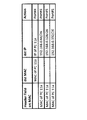
図3は、スイッチ制御装置(OFC)700がGWS情報420として記憶する情報の例を示す説明図である。図3では、例えば、OFS100,200,300,400がGWSとして決定されたことを意味している。また、例えば、OFS100には、IPアドレス帯域が“192.168.0.0/26”であるサブネットワークが対応付けられたことを意味している。なお、経路計算処理部350は、OFS500もGWSとして決定してもよい。
FIG. 3 is an explanatory diagram illustrating an example of information stored as the
また、経路計算処理部350は、トポロジ情報380に基づいて中継スイッチも決定し、中継スイッチに該当するOFSを示す情報の書き込みもGWS管理部430に指示する。本実施形態では、OFS500が中継スイッチとして決定された場合を例にして説明する。
The route
端末に接続されているGWSは、端末からパケットを受信したときに、そのパケットに対応するフローエントリがそのGWSに設定されていない場合、そのパケットを「パケットイン」メッセージとともに、スイッチ制御装置700に送信する。このとき、GWSは、ステーション情報もスイッチ制御装置700に送信する。ステーション情報は、パケットの送信元の端末のMACアドレスと、その端末に接続されたOFSのDPID(Datapath ID )/ポート番号との組を示す情報である。
When the GWS connected to the terminal receives a packet from the terminal and the flow entry corresponding to the packet is not set in the GWS, the GWS sends the packet to the
ステーション情報受付部390は、端末が接続されている各OFSから通知されたステーション情報を、通信処理部305を介して受け取り、そのステーション情報の書き込みをステーション情報管理部405に指示する。
The station
ステーション情報管理部405は、例えば、メモリを備える。そして、ステーション情報管理部405は、端末が接続されている各OFSからステーション情報受付部390が受け取ったステーション情報を、ステーション情報受付部390の指示に従って、そのメモリに書き込む。ステーション情報は、GWSに接続されている端末のアドレス(MACアドレス)を示していると言うことができる。従って、ステーション情報管理部405は、GWSに接続されている端末のアドレスを記憶する端末アドレス記憶手段と称することもできる。
The station
フロー設定処理部340は、端末が接続されているOFSが「パケットイン」メッセージとともに送信したパケットを、通信処理部305を介して受け取る。そして、フロー設定処理部340は、「パケットイン」メッセージとともに送信されたステーション情報、経路計算処理部350が把握しているトポロジ情報380およびGWS情報420に基づいて、そのパケットを送信したOFSに設定するフローエントリを生成する。そして、フロー設定処理部340は、通信処理部305を介して、そのOFSにフローエントリを送信することによって、そのOFSにフローエントリを設定する。
The flow setting
コンフィグ情報管理部320、トポロジ情報受付部360、トポロジ情報管理部370、ステーション情報受付部390、ステーション情報管理部405、経路計算処理部350、GWS管理部430およびフロー設定処理部340は、例えば、スイッチ制御プログラムに従って動作するコンピュータのCPUによって実現される。この場合、CPUは、例えば、コンピュータのプログラム記憶装置(図示略)等のプログラム記録媒体からスイッチ制御プログラムを読み込み、そのスイッチ制御プログラムに従って、コンフィグ情報管理部320、トポロジ情報受付部360、トポロジ情報管理部370、ステーション情報受付部390、ステーション情報管理部405、経路計算処理部350、GWS管理部430およびフロー設定処理部340として動作すればよい。また、コンフィグ情報管理部320、トポロジ情報受付部360、トポロジ情報管理部370、ステーション情報受付部390、ステーション情報管理部405、経路計算処理部350、GWS管理部430およびフロー設定処理部340が別々のハードウェアによって実現されていてもよい。
The configuration
次に、本発明の処理経過の例について説明する。 Next, an example of processing progress of the present invention will be described.
まず、事前準備に該当する処理について説明する。コンフィグ情報管理部320は、スイッチ制御装置700のユーザからコンフィグ設定部310を介して、コンフィグ情報を指定される。すると、コンフィグ情報管理部320は、そのコンフィグ情報をメモリに書き込む。この結果、コンフィグ情報管理部320は、例えば、管理対象ネットワークのIPアドレス帯域が“192.168.0.0/24(図1参照)”であることを示すコンフィグ情報を記憶する。
First, a process corresponding to advance preparation will be described. The configuration
また、スイッチ制御装置700と各OFSとが接続されると、各OFSは、LLDP等の標準的な方法でOFSのネットワークのトポロジを検出し、トポロジ情報をスイッチ制御装置700に通知する。トポロジ情報受付部360は、各OFSから通知されたトポロジ情報の書き込みをトポロジ情報管理部370に指示する。トポロジ情報管理部370は、この指示に従い、メモリにトポロジ情報を書き込む。この結果、トポロジ情報管理部370は、OFSのネットワークのトポロジ情報を記憶する。
When the
コンフィグ情報、およびOFSのネットワークのトポロジ情報が記憶された後、経路計算処理部350は、そのトポロジ情報およびコンフィグ情報に基づいて、管理対象ネットワーク内のどのOFSをGWSとするかを決定し、また、管理対象ネットワークのIPアドレス帯域をどのように分割するかを決定する。さらに、経路計算処理部350は、GWSと決定したOFSに、分割によって得られるどのサブネットワークのIPアドレス(IPアドレス帯域)を対応付けるかを決定する。経路計算処理部350は、この決定結果を示すGWS情報420の書き込みをGWS管理部430に指示する。本例では、OFS100,200,300,400,500がGWSとして決定されたものして説明する。また、OFS100,200,300,400とサブネットワークのIPアドレスとの対応関係が、図3に示すように決定されたものとする。
After the configuration information and the network topology information of the OFS are stored, the route
また、経路計算処理部350は、トポロジ情報に基づいて中継スイッチも決定し、中継スイッチに該当するOFSを示す情報の書き込みもGWS管理部430に指示する。本実施形態では、スイッチ500が中継スイッチとして決定されたものとして説明する。
The route
GWSとサブネットワークのIPアドレスとの対応関係、および中継スイッチが決定されると、フロー設定処理部340は、GWSに対応するサブネットワークのIPアドレス(IPアドレス帯域)と、そのIPアドレスに対応するアクションを規定したフローエントリを、GWS(ただし、中継スイッチであるOFS500は除く。)毎に作成し、中継スイッチ(OFS500)にそのフローエントリを設定する。フロー設定処理部340は、アクションとして、フローエントリ内に記述したIPアドレスに対応するGWSにパケットを転送する旨を記述する。
When the correspondence between the GWS and the IP address of the subnetwork and the relay switch are determined, the flow setting
フロー設定処理部340が中継スイッチ(OFS500)に対して設定するフローエントリの例を図4に示す。図4において、例えば、“Port#1”は、ポート#1からパケットを出力することを意味する。例えば、図4に示す1番目のフローエントリは、宛先アドレスが“192.168.0.0/26”に該当しているパケットを、ポート#1から出力することを規定している。OFS500のポート#1は、OFS100に接続されている(図1参照)。従って、OFS500のポート#1からパケットを出力するということは、OFS100にパケットを転送することを意味する。ここでは、図4に示す1番目のフローエントリを例にして説明したが、図4に示す他の3つのフローエントリは、OFS200,300,400に対応する同様のフローエントリである。
An example of a flow entry that the flow setting
フロー設定処理部340は、中継スイッチに対して、GWSに対応するサブネットワークのアドレスに宛先アドレスが該当しているパケットをそのGWSに転送することを規定したフローエントリを、中継スイッチ以外のGWS毎に設定している。フロー設定処理部340は、OFS500に向けてパケットを転送する旨を規定したフローエントリをOFS500に設定する必要はない。
The flow setting
以上が、事前準備に該当する処理である。 The above is the process corresponding to the advance preparation.
次に、端末間の通信が発生したときの処理経過について説明する。ここでは、まず、通信を行う端末のアドレスが、その端末に接続されているGWSに対応するサブネットワークのアドレスに該当する場合について説明する。 Next, processing progress when communication between terminals occurs will be described. Here, a case will be described first where the address of a terminal that performs communication corresponds to the address of a subnetwork corresponding to the GWS connected to the terminal.
図5および図6は、通信を行う端末のアドレスが、その端末に接続されているGWSに対応するサブネットワークのアドレスに該当する場合の処理経過の例を示す説明図である。なお、図5および図6は、図1の一部を抜き出し、ステップ番号を付加した図である。 5 and 6 are explanatory diagrams illustrating an example of processing progress when the address of a terminal that performs communication corresponds to the address of a subnetwork corresponding to the GWS connected to the terminal. 5 and 6 are diagrams in which a part of FIG. 1 is extracted and step numbers are added.
ここでは、PC11aのIPアドレスが、PC11aが接続されているGWS(OFS100)に対応するサブネットワークのIPアドレスに該当し、DNSサーバ30のIPアドレスが、DNSサーバ30が接続されているGWS(OFS400)に対応するサブネットワークのIPアドレスに該当しているものとして説明する。
Here, the IP address of the
まず、PC11aが、PC11aを送信元としDNSサーバ30を宛先とするパケットをOFS100に送信する(図5に示すステップS1)。
First, the
OFS100には、このパケットに対応するフローエントリはまだ設定されていないものとする。この場合、OFS100は、そのパケットを「パケットイン」メッセージとともに、スイッチ制御装置700に送信する(図5に示すステップS2)。このとき、OFS100は、PC11aおよびOFS100に関するステーション情報もスイッチ制御装置700に送信する。
It is assumed that the flow entry corresponding to this packet has not been set in the
スイッチ制御装置700のフロー設定処理部340は、そのパケットおよびステーション情報を受け取ると、「パケットイン」メッセージを送信したOFS100に設定するフローエントリを作成し、OFS100に対してそのフローエントリを設定する(図5に示すステップS3)。図7は、ステップS3でOFS100に設定されるフローエントリの例を示す説明図である。
Upon receiving the packet and station information, the flow setting
フロー設定処理部340は、OFS100から受け取ったステーション情報から、パケットの送信元の端末であるPC11aが、OFS100のポート#Xに接続されていることを認識する。フロー設定処理部340は、そのステーション情報に基づいて、パケットの送信元の端末(本例ではPC11a)を宛先とするパケットをその端末に転送することを規定したフローエントリをOFS100に対して設定する。図7に示す1番目のフローエントリは、このフローエントリである。図7に示す1番目のフローエントリは、宛先MACアドレスおよび宛先IPアドレスがPC11aのMACアドレスおよびIPアドレスに合致するパケットをポート#Xから出力する(すなわち、PC11aに転送する)ことを規定している。
From the station information received from the
さらに、フロー設定処理部340は、OFS100に対して、OFS100以外のGWS毎に、その端末を送信元とし、GWSに対応するサブネットワークのアドレスに宛先アドレスが該当しているパケットを中継スイッチに転送することを規定したフローエントリを設定する。図7に示す2番目から4番目までの3つのフローエントリが、このフローエントリである。例えば、図7に示す2番目のフローエントリは、送信元MACアドレスがPC11aのMACアドレスであり、宛先IPアドレスが、OFS200に対応するサブネットワークのアドレス(“192.168.0.64/26 ”)に該当するパケットを、ポート#1から出力する(すなわち、中継スイッチに転送する)ことを規定している。図7に示す3番目および4番目のフローエントリは、OFS300,400に対応する同様のフローエントリである。
Further, the flow setting
また、スイッチ制御装置700のステーション情報受付部390は、OFS100から受け取ったステーション情報をステーション情報管理部405に記憶させる。
Further, the station
ステップS3の後、フロー設定処理部340は、「パケットイン」メッセージとともに受信したパケットの宛先MACアドレスを有する端末が、どのGWSのどのポートに接続されているかを、ステーション情報管理部405に記憶されているステーション情報410に基づいて検査する。ただし、ここでは、パケットの宛先MACアドレスを有する端末(DNSサーバ30)は、ステーション情報をスイッチ制御装置700に送信していない。そのため、フロー設定処理部340は、「パケットイン」メッセージとともに受信したパケットの宛先MACアドレスを有する端末が、どのGWSのどのポートに接続されているかを特定できない。この場合、フロー設定処理部340は、ステップS2でOFS100から受け取ったパケットと、そのパケットをブロードキャスト送信することを示す「パケットアウト」メッセージとを、全てのGWSに送信する(図6に示すステップS4)。
After step S3, the flow setting
このフロー設定処理部340の動作は、GWSからパケットを受信したときに、そのパケットの宛先アドレスがステーション情報管理部405に記憶されていない場合、全てのGWSにそのパケットをブロードキャスト送信させる動作であると言うことができる。
The operation of the flow setting
OFS400は、その「パケットアウト」メッセージに基づき、OFS400のポート#Zからパケットを出力する(図6に示すステップS5)。この結果、DNSサーバ30は、PC11aを送信元とするパケットを、OFS400から受信する。
The
DNSサーバ30は、PC11aを送信元とするパケットを受信すると、PC11aへの応答として、DNSサーバ30を送信元としPC11aを宛先とするパケットを、OFS400に送信する(図6に示すステップS6)。
When the
OFS400には、このパケットに対応するフローエントリはまだ設定されていないものとする。この場合、OFS400は、そのパケットを「パケットイン」メッセージとともに、スイッチ制御装置700に送信する(図6に示すステップS7)。このとき、OFS400は、DNSサーバ30およびOFS400に関するステーション情報もスイッチ制御装置700に送信する。
It is assumed that a flow entry corresponding to this packet has not been set in the
スイッチ制御装置700のフロー設定処理部340は、そのパケットおよびステーション情報を受け取ると、「パケットイン」メッセージを送信したOFS400に設定するフローエントリを作成し、OFS400に対してそのフローエントリを設定する(図6に示すステップS8)。図8は、ステップS8でOFS400に設定されるフローエントリの例を示す説明図である。
Upon receiving the packet and station information, the flow setting
フロー設定処理部340は、OFS400から受け取ったステーション情報から、パケットの送信元の端末であるDNSサーバ30が、OFS400のポート#Zに接続されていることを認識する。フロー設定処理部340は、そのステーション情報に基づいて、パケットの送信元の端末(本例ではDNSサーバ30)を宛先とするパケットをその端末に転送することを規定したフローエントリをOFS400に対して設定する。図8に示す1番目のフローエントリは、このフローエントリである。図8に示す1番目のフローエントリは、宛先MACアドレスおよび宛先IPアドレスがDNSサーバ30のMACアドレスおよびIPアドレスに合致するパケットをポート#Zから出力する(すなわち、DNSサーバ30に転送する)ことを規定している。
The flow setting
さらに、フロー設定処理部340は、OFS400に対して、OFS400以外のGWS毎に、その端末を送信元とし、GWSに対応するサブネットワークのアドレスに宛先アドレスが該当しているパケットを中継スイッチに転送することを規定したフローエントリを設定する。図8に示す2番目から4番目までの3つのフローエントリが、このフローエントリである。例えば、図8に示す2番目のフローエントリは、送信元MACアドレスがDNSサーバ30のMACアドレスであり、宛先IPアドレスが、OFS100に対応するサブネットワークのアドレス(“192.168.0.0/26”)に該当するパケットを、ポート#1から出力する(すなわち、中継スイッチに転送する)ことを規定している。図8に示す3番目および4番目のフローエントリは、OFS200,300に対応する同様のフローエントリである。
Further, the flow setting
また、スイッチ制御装置700のステーション情報受付部390は、OFS400から受け取ったステーション情報をステーション情報管理部405に記憶させる。
Further, the station
ステップS8の後、フロー設定処理部340は、「パケットイン」メッセージとともに受信したパケットの宛先MACアドレスを有する端末(ここでは、PC11a)が、どのGWSのどのポートに接続されているかを、ステーション情報管理部405に記憶されているステーション情報410に基づいて検査する。PC11aがOFS100のポート#Xに接続されていることを示すステーション情報は、既にステーション情報管理部405に記憶されている。従って、フロー設定処理部340は、パケットの宛先MACアドレスを有する端末(PC11a)がOFS100のポート#Xに接続されていることを認識する。そして、フロー設定処理部340は、ステップS7でOFS400から受け取ったパケットと、そのパケットをポート#Xから出力することを示す「パケットアウト」メッセージとを、OFS100(パケットの宛先MACアドレスを有する端末に接続されているGWS)に送信する(図5に示すステップS9)。
After step S8, the flow setting
OFS100は、その「パケットアウト」メッセージに基づき、OFS100のポート#Xからパケットを出力する(図5に示すステップS10)。この結果、PC11aは、DNSサーバ30を送信元とするパケットを、OFS100から受信する。
The
上記のステップS1〜S10の処理以後、ステップS1〜S10の過程でGWS(OFS100,400)に設定されたフローエントリと、事前準備の段階で中継スイッチ(OFS500)に設定されたフローエントリとにより、GWSが、PC11aおよびDNSサーバ30とが送受信するパケットを転送することができる。
After the processing of steps S1 to S10, the flow entry set in the GWS (
例えば、OFS100が、PC11aからDNSサーバ30宛てのパケットを受信したとする。このパケットの宛先IPアドレス(DNSサーバ30のIPアドレス)は、OFS400に対応するサブネットワークのIPアドレス(“192.168.0.192/26”)に該当する。従って、OFS100は、図7に示す4番目のフローエントリに従い、ポート#1からパケットを出力する。中継スイッチ(OFS500)は、このパケットを受信すると、事前準備の段階でOFS500に設定されたフローエントリ(具体的には、図4に示す4番目のフローエントリ)に従い、ポート#4からパケットを出力する。OFS400は、このパケットを受信すると、図8に示す1番目のフローエントリに従い、ポート#Zからパケットを出力する。この結果、DNSサーバ30にパケットが到達する。
For example, it is assumed that the
また、例えば、OFS400が、DNSサーバ30からPC11a宛てのパケットを受信したとする。このパケットの宛先IPアドレス(PC11aのIPアドレス)は、OFS100に対応するサブネットワークのIPアドレス(“192.168.0.0/26”)に該当する。従って、OFS400は、図8に示す2番目のフローエントリに従い、ポート#1からパケットを出力する。中継スイッチ(OFS500)は、このパケットを受信すると、事前準備の段階でOFS500に設定されたフローエントリ(具体的には、図4に示す1番目のフローエントリ)に従い、ポート#1からパケットを出力する。OFS100は、このパケットを受信すると、図7に示す1番目のフローエントリに従い、ポート#Xからパケットを出力する。この結果、PC11aにパケットが到達する。
For example, it is assumed that the
次に、通信を行う端末のアドレスが、その端末に接続されているGWSに対応するサブネットワークのアドレスに該当しない場合について説明する。 Next, a case where the address of the terminal that performs communication does not correspond to the address of the subnetwork corresponding to the GWS connected to the terminal will be described.
図9、図10および図11は、通信を行う端末のアドレスが、その端末に接続されているGWSに対応するサブネットワークのアドレスに該当しない場合の処理経過の例を示す説明図である。なお、図9、図10および図11は、図1の一部を抜き出し、ステップ番号を付加した図である。 FIG. 9, FIG. 10 and FIG. 11 are explanatory diagrams showing examples of processing progress when the address of a terminal that performs communication does not correspond to the address of a subnetwork corresponding to the GWS connected to the terminal. 9, FIG. 10 and FIG. 11 are diagrams in which a part of FIG. 1 is extracted and step numbers are added.
ここでは、PC11bのIPアドレスが、PC11bが接続されているGWS(OFS100)に対応するサブネットワークのIPアドレスに該当していないものとして説明する。また、PC11bのIPアドレスは、OFS200に対応するサブネットワークのIPアドレスに該当しているものとする。なお、DNSサーバ30のIPアドレスは、上記の場合と同様に、DNSサーバ30が接続されているGWS(OFS400)に対応するサブネットワークIPアドレスに該当しているものとする。
Here, description will be made assuming that the IP address of the
まず、PC11bが、PC11bを送信元としDNSサーバ30を宛先とするパケットをOFS100に送信する(図9に示すステップT1)。
First, the
OFS100には、このパケットに対応するフローエントリはまだ設定されていないものとする。この場合、OFS100は、そのパケットを「パケットイン」メッセージとともに、スイッチ制御装置700に送信する(図9に示すステップT2)。このとき、OFS100は、PC11bおよびOFS100に関するステーション情報もスイッチ制御装置700に送信する。
It is assumed that the flow entry corresponding to this packet has not been set in the
スイッチ制御装置700のフロー設定処理部340は、そのパケットおよびステーション情報を受け取ると、「パケットイン」メッセージを送信したOFS100に設定するフローエントリを作成し、OFS100に対してそのフローエントリを設定する(図9に示すステップT3a)。図12は、ステップT3aでOFS100に設定されるフローエントリの例を示す説明図である。
Upon receiving the packet and station information, the flow setting
フロー設定処理部340は、OFS100から受け取ったステーション情報から、パケットの送信元の端末であるPC11bが、OFS100のポート#Yに接続されていることを認識する。フロー設定処理部340は、そのステーション情報に基づいて、パケットの送信元の端末(本例ではPC11b)を宛先とするパケットをその端末に転送することを規定したフローエントリをOFS100に対して設定する。図12に示す1番目のフローは、このフローエントリである。図12に示す1番目のフローエントリは、宛先MACアドレスおよび宛先IPアドレスがPC11bのMACアドレスおよびIPアドレスに合致するパケットをポート#Yから出力する(すなわち、PC11bに転送する)ことを規定している。
From the station information received from the
さらに、フロー設定処理部340は、OFS100に対して、OFS100以外のGWS毎に、その端末を送信元とし、GWSに対応するサブネットワークのアドレスに宛先アドレスが該当しているパケットを中継スイッチに転送することを規定したフローエントリを設定する。図12に示す2番目から4番目までの3つのフローエントリが、このフローエントリである。例えば、図12に示す2番目のフローエントリは、送信元MACアドレスがPC11bのMACアドレスであり、宛先IPアドレスが、OFS200に対応するサブネットワークのアドレス(“192.168.0.64/26 ”)に該当するパケットを、ポート#1から出力する(すなわち、中継スイッチに転送する)ことを規定している。図12に示す3番目および4番目のフローエントリは、OFS300,400に対応する同様のフローエントリである。
Further, the flow setting
また、スイッチ制御装置700のステーション情報受付部390は、OFS100から受け取ったステーション情報をステーション情報管理部405に記憶させる。
Further, the station
また、フロー設定処理部340は、ステップT2でOFS100から受け取ったパケットの送信元IPアドレスを参照し、その送信元IPアドレス(PC11bのIPアドレス)が、ステップT2でそのパケットを送信したOFS100に対応するサブネットワークのアドレス(“192.168.0.0/26”)に該当しないことを認識する。この場合、フロー設定処理部340は、そのパケットの送信元IPアドレスが該当するサブネットワークに対応するGWSに対して、ステップT2でそのパケットを送信したGWS(OFS100)にそのパケットの送信元アドレスを宛先とするパケットを転送することを規定したフローエントリを設定する(図10に示すステップT3b)。ステップT3bにおいて、まず、フロー設定処理部340は、そのパケットの送信元IPアドレスが該当するサブネットワークに対応するGWSを、GWS情報420に基づいて特定する。ここでは、パケットの送信元IPアドレスは、PC11bのIPアドレスである。そして、PC11bのIPアドレスは、OFS200に対応するサブネットワークのIPアドレスに該当している。従って、フロー設定処理部340は、パケットの送信元IPアドレスが該当するサブネットワークに対応するGWSとして、OFS200を特定する。そして、フロー設定処理部340は、OFS200に対して、ステップT2でそのパケットを送信したGWS(OFS100)にそのパケットの送信元アドレスを宛先とするパケットを転送することを規定したフローエントリを設定する。
The flow setting
図13は、ステップT3bでOFS200に設定されるフローエントリの例を示す説明図である。図13に示すフローエントリは、宛先MACアドレスおよび宛先IPアドレスが、ステップT2でOFS100から受け取ったパケットの送信元MACアドレスおよび送信元IPアドレス(すなわち、PC11bのMACアドレスおよびIPアドレス)に合致するパケットをポート#Wから出力する(すなわち、OFS100に転送する)ことを規定している。
FIG. 13 is an explanatory diagram showing an example of a flow entry set in the
ステップT3bの後、フロー設定処理部340は、「パケットイン」メッセージとともに受信したパケットの宛先MACアドレスを有する端末が、どのGWSのどのポートに接続されているかを、ステーション情報管理部405に記憶されているステーション情報410に基づいて検査する。ただし、ここでは、パケットの宛先MACアドレスを有する端末(DNSサーバ30)は、ステーション情報をスイッチ制御装置700に送信していない。そのため、フロー設定処理部340は、「パケットイン」メッセージとともに受信したパケットの宛先MACアドレスを有する端末が、どのGWSのどのポートに接続されているかを特定できない。この場合、フロー設定処理部340は、ステップT2でOFS100から受け取ったパケットと、そのパケットをブロードキャスト送信することを示す「パケットアウト」メッセージとを、全てのGWSに送信する(図11に示すステップT4)。
After step T3b, the flow setting
ステップT4の動作は、ステップS4と同様の動作であり、GWSからパケットを受信したときに、そのパケットの宛先アドレスがステーション情報管理部405に記憶されていない場合、全てのGWSにそのパケットをブロードキャスト送信させる動作であると言うことができる。
The operation in step T4 is the same as that in step S4. When a packet is received from the GWS, if the destination address of the packet is not stored in the station
OFS400は、その「パケットアウト」メッセージに基づき、OFS400のポート#Zからパケットを出力する(図11に示すステップT5)。この結果、DNSサーバ30は、PC11bを送信元とするパケットを、OFS400から受信する。
The
DNSサーバ30は、PC11bを送信元とするパケットを受信すると、PC11bへの応答として、DNSサーバ30を送信元としPC11bを宛先とするパケットを、OFS400に送信する(図11に示すステップT6)。
When the
OFS400には、このパケットに対応するフローエントリはまだ設定されていないものとする。この場合、OFS400は、そのパケットを「パケットイン」メッセージとともに、スイッチ制御装置700に送信する(図11に示すステップT7)。このとき、OFS400は、DNSサーバ30およびOFS400に関するステーション情報もスイッチ制御装置700に送信する。
It is assumed that a flow entry corresponding to this packet has not been set in the
スイッチ制御装置700のフロー設定処理部340は、そのパケットおよびステーション情報を受け取ると、「パケットイン」メッセージを送信したOFS400に設定するフローエントリを作成し、OFS400に対してそのフローエントリを設定する(図11に示すステップT8)。図14は、ステップT8でOFS400に設定されるフローエントリの例を示す説明図である。
Upon receiving the packet and station information, the flow setting
フロー設定処理部340は、OFS400から受け取ったステーション情報から、パケットの送信元の端末であるDNSサーバ30が、OFS400のポート#Zに接続されていることを認識する。フロー設定処理部340は、そのステーション情報に基づいて、パケットの送信元の端末(本例ではDNSサーバ30)を宛先とするパケットをその端末に転送することを規定したフローエントリをOFS400に対して設定する。図14に示す1番目のフローエントリは、このフローエントリである。図14に示す1番目のフローエントリは、宛先MACアドレスおよび宛先IPアドレスがDNSサーバ30のMACアドレスおよびIPアドレスに合致するパケットをポート#Zから出力する(すなわち、DNSサーバ30に転送する)ことを規定している。
The flow setting
さらに、フロー設定処理部340は、OFS400に対して、OFS400以外のGWS毎に、その端末を送信元とし、GWSに対応するサブネットワークのアドレスに宛先アドレスが該当しているパケットを中継スイッチに転送することを規定したフローエントリを設定する。図14に示す2番目から4番目まえの3つのフローエントリが、このフローエントリである。例えば、図14に示す2番目のフローエントリは、送信元MACアドレスがDNSサーバ30のMACアドレスであり、宛先IPアドレスが、OFS100に対応するサブネットワークのアドレス(“192.168.0.0/26”)に該当するパケットを、ポート#1から出力する(すなわち、中継スイッチに転送する)ことを規定している。図14に示す3番目および4番目のフローエントリは、OFS200,300に対応する同様のフローエントリである。
Further, the flow setting
また、スイッチ制御装置700のステーション情報受付部390は、OFS400から受け取ったステーション情報をステーション情報管理部405に記憶させる。
Further, the station
ステップT8の動作は、前述のステップS8の動作と同様であり、図14に示すフローエントリは、図8に示すフローエントリと同様のフローエントリである。 The operation of step T8 is the same as the operation of step S8 described above, and the flow entry shown in FIG. 14 is the same flow entry as the flow entry shown in FIG.
ステップT8の後、フロー設定処理部340は、「パケットイン」メッセージとともに受信したパケットの宛先MACアドレスを有する端末(ここでは、PC11b)が、どのGWSのどのポートに接続されているかを、ステーション情報管理部405に記憶されているステーション情報410に基づいて検査する。PC11bがOFS100のポート#Yに接続されていることを示すステーション情報は、既にステーション情報管理部405に記憶されている。従って、フロー設定処理部340は、パケットの宛先MACアドレスを有する端末(PC11b)がOFS100のポート#Yに接続されていることを認識する。そして、フロー設定処理部340は、ステップT7でOFS400から受け取ったパケットと、そのパケットをポート#Yから出力することを示す「パケットアウト」メッセージとを、OFS100(パケットの宛先MACアドレスを有する端末に接続されているGWS)に送信する(図9に示すステップT9)。
After step T8, the flow setting
OFS100は、その「パケットアウト」メッセージに基づき、OFS100のポート#Yからパケットを出力する(図9に示すステップT10)。この結果、PC11bは、DNSサーバ30を送信元とするパケットを、OFS100から受信する。
The
上記のステップT1〜T10の処理後、ステップT1〜T10の過程でGWS(OFS100,200,400)に設定されたフローエントリと、事前準備の段階で中継スイッチ(OFS500)に設定されたフローエントリとにより、GWSが、PC11bおよびDNSサーバ30とが送受信するパケットを転送することができる。
After the processing of steps T1 to T10, the flow entry set in the GWS (
例えば、OFS100が、PC11bからDNSサーバ30宛てのパケットを受信したとする。このパケットの宛先IPアドレス(DNSサーバ30のIPアドレス)は、OFS400に対応するサブネットワークのIPアドレス(“192.168.0.192/26”)に該当する。従って、OFS100は、図12に示す4番目のフローエントリに従い、ポート#1からパケットを出力する。中継スイッチ(OFS500)は、このパケットを受信すると、事前準備の段階でOFS500に設定されたフローエントリ(具体的には、図4に示す4番目のフローエントリ)に従い、ポート#4からパケットを出力する。OFS400は、このパケットを受信すると、図14に示す1番目のフローエントリに従い、ポート#Zからパケットを出力する。この結果、DNSサーバ30にパケットが到達する。
For example, it is assumed that the
また、例えば、OFS400が、DNSサーバ30からPC11b宛てのパケットを受信したとする。このパケットの宛先IPアドレス(PC11bのIPアドレス)は、OFS200に対応するサブネットワークのIPアドレス(“192.168.0.64/26 ”)に該当する。従って、OFS400は、図14に示す3番目のフローエントリに従い、ポート#1からパケットを出力する。中継スイッチ(OFS500)は、このパケットを受信すると、事前準備の段階でOFS500に設定されたフローエントリ(具体的には、図4に示す2番目のフローエントリ)に従い、ポート#2からパケットを出力する。OFS200は、このパケットを受信すると、図13に示すフローエントリに従い、ポート#Wからパケットを出力する。この結果、OFS110は、OFS200から、OFS500を介さずにパケットを受信する。そして、OFS100は、図12に示す1番目のフローエントリに従い、ポート#Yからパケットを出力する。この結果、PC11bにパケットが到着する。
For example, it is assumed that the
次に、本発明の効果について説明する。 Next, the effect of the present invention will be described.
まず、本発明において、1つのGWSに設定されるフローエントリの数を説明する。1つのGWSに設定されるフローエントリであって、中継スイッチにパケットを転送することを規定したフローエントリの数は、以下に示す式(1)で表される。 First, the number of flow entries set in one GWS in the present invention will be described. The number of flow entries that are set in one GWS and that specify that a packet is transferred to the relay switch is expressed by the following equation (1).
GWSに接続されている端末の数×(GWSの数−1) ・・・(1) Number of terminals connected to GWS × (Number of GWS−1) (1)
また、1つのGWSに設定されるフローエントリであって、端末にパケットを転送することを規定したフローエントリの数は、GWSに接続されている端末の数である。 In addition, the number of flow entries that are set in one GWS and specify that a packet is transferred to a terminal is the number of terminals that are connected to the GWS.
従って、1つのGWSに設定されるフローエントリの数は、「GWSに接続されている端末の数×(GWSの数−1)」と「GWSに接続されている端末の数」の合計であり、以下に示す式(2)で表される。 Therefore, the number of flow entries set in one GWS is the sum of “number of terminals connected to GWS × (number of GWS−1)” and “number of terminals connected to GWS”. It is represented by the following formula (2).
GWSに接続されている端末の数×GWSの数 ・・・(2) Number of terminals connected to GWS x number of GWS (2)
次に、一般的な技術において、1つのOFSに設定されるフローエントリの数を説明する。一般的な技術において1つのOFSに設定されるフローエントリであって、中継スイッチにパケットを転送することを規定したフローエントリの数は、以下に示す式(3)で表される。 Next, the number of flow entries set in one OFS in a general technique will be described. In the general technique, the number of flow entries that are set in one OFS and specify that the packet is transferred to the relay switch is expressed by the following equation (3).
OFSに接続されている端末の数×宛先となる端末の数 ・・・(3) Number of terminals connected to OFS x number of destination terminals (3)
また、一般的な技術において1つのOFSに設定されるフローエントリであって、端末にパケットを転送することを規定したフローエントリの数は、OFSに接続されている端末の数である。 In addition, the number of flow entries that are set in one OFS in a general technique and specify that a packet is transferred to a terminal is the number of terminals that are connected to the OFS.
従って、一般的な技術において1つのOFSに設定されるフローエントリの数は、「OFSに接続されている端末の数×宛先となる端末の数」と「OFSに接続されている端末の数」の合計であり、以下に示す式(4)で表される。 Therefore, in general technology, the number of flow entries set in one OFS is “the number of terminals connected to OFS × the number of terminals serving as destinations” and “the number of terminals connected to OFS”. And is represented by the following formula (4).
OFSに接続されている端末の数×(宛先となる端末の数+1) ・・・(4) Number of terminals connected to OFS × (number of destination terminals + 1) (4)
一般的な技術における1つのOFSに設定されるフローエントリの数に対する、本発明における1つのOFSに設定されるフローエントリの数の割合は、以下に示す式(5)で表される。 The ratio of the number of flow entries set in one OFS in the present invention to the number of flow entries set in one OFS in a general technique is expressed by the following equation (5).

「GWSに接続されている端末の数」=「OFSに接続されている端末の数」であるので、式(5)は、以下に示す式(6)で表される。 Since “the number of terminals connected to the GWS” = “the number of terminals connected to the OFS”, Expression (5) is expressed by Expression (6) below.
GWSの数/(宛先となる端末の数+1) ・・・(6) Number of GWS / (Number of destination terminals + 1) (6)
ここで、GWSの数は、例えば、数台から数十台程度である。また、宛先となる端末の数は、例えば、数十台から数百台である。よって、本発明によれば、1つのGWSに設定されるフローエントリの数を、一般的な技術において1つのOFSに設定されるフローエントリの数の1/10から1/100程度に抑えることができる。 Here, the number of GWS is about several to several tens, for example. Further, the number of terminals serving as destinations is, for example, several tens to several hundreds. Therefore, according to the present invention, the number of flow entries set in one GWS can be suppressed to about 1/10 to 1/100 of the number of flow entries set in one OFS in a general technique. it can.
従って、本発明によれば、OFSに接続されている端末にアクセスが集中する場合であっても、そのOFSに設定されるフローエントリの数の増加を防止することができる。 Therefore, according to the present invention, an increase in the number of flow entries set in an OFS can be prevented even when access is concentrated on terminals connected to the OFS.
次に、本発明の概要について説明する。図15は、本発明のスイッチ制御装置の概要を示すブロック図である。スイッチ制御装置51は、サブネットワークに対応付けられたスイッチであるゲートウェイスイッチ、およびゲートウェイスイッチ間でパケットを中継する中継スイッチに対して、パケットに対するアクションを規定したフローエントリを設定するフローエントリ設定手段52(例えば、フロー設定処理部340)を備える。
Next, the outline of the present invention will be described. FIG. 15 is a block diagram showing an outline of the switch control device of the present invention. The
フローエントリ設定手段52は、中継スイッチに対して、ゲートウェイスイッチに対応するサブネットワークのアドレスに宛先アドレスが該当しているパケットをそのゲートウェイスイッチに転送することを規定したフローエントリを、中継スイッチ以外のゲートウェイスイッチ毎に設定する。 The flow entry setting means 52 sends a flow entry that specifies that a packet whose destination address corresponds to the address of the subnetwork corresponding to the gateway switch to the gateway switch is transferred to the gateway switch. Set for each gateway switch.
また、フローエントリ設定手段52は、ゲートウェイスイッチからパケットを受信したときに、そのゲートウェイスイッチに対して、パケットの送信元の端末を宛先とするパケットをその端末に転送することを規定したフローエントリを設定する。さらに、フローエントリ設定手段52は、そのゲートウェイスイッチに対して、当該ゲートウェイスイッチ以外のゲートウェイスイッチ毎に、その端末を送信元とし、ゲートウェイスイッチに対応するサブネットワークのアドレスに宛先アドレスが該当しているパケットを中継スイッチに転送することを規定したフローエントリを設定する。 Further, the flow entry setting means 52, when receiving a packet from the gateway switch, sends a flow entry that specifies that the packet destined for the terminal of the packet transmission source is transferred to the gateway switch. Set. Further, the flow entry setting means 52 uses the terminal as the transmission source for each gateway switch other than the gateway switch, and the destination address corresponds to the address of the subnetwork corresponding to the gateway switch. Set the flow entry that specifies that the packet is forwarded to the relay switch.
そのような構成により、スイッチに接続されている端末にアクセスが集中する場合であっても、そのスイッチに設定されるフローエントリの数の増加を防止できる。 With such a configuration, it is possible to prevent an increase in the number of flow entries set in the switch even when access is concentrated on terminals connected to the switch.
フローエントリ設定手段52が、ゲートウェイスイッチからパケットを受信したときに、パケットの送信元アドレスがそのゲートウェイスイッチに対応するサブネットワークのアドレスに該当していない場合、パケットの送信元アドレスに該当するサブネットワークに対応するゲートウェイスイッチに対して、そのパケットを送信したゲートウェイスイッチにそのパケットの送信元アドレスを宛先とするパケットを転送することを規定したフローエントリを設定する構成であってもよい。 When the flow entry setting means 52 receives a packet from a gateway switch, if the packet source address does not correspond to the address of the subnetwork corresponding to the gateway switch, the subnetwork corresponding to the packet source address For the gateway switch corresponding to the above, a configuration may be used in which a flow entry that defines that a packet destined for the source address of the packet is transferred to the gateway switch that transmitted the packet is set.
ゲートウェイスイッチに接続されている端末のアドレスを記憶する端末アドレス記憶手段(例えば、ステーション情報管理部405)を備え、
フローエントリ設定手段52が、
ゲートウェイスイッチからパケットを受信したときに、そのパケットの宛先アドレスが端末アドレス記憶手段に記憶されていない場合、全てのゲートウェイスイッチにそのパケットをブロードキャスト送信させる構成であってもよい。
Terminal address storage means (for example, station information management unit 405) for storing the address of the terminal connected to the gateway switch,
The flow entry setting means 52
When a packet is received from the gateway switch, if the destination address of the packet is not stored in the terminal address storage unit, the configuration may be such that all the gateway switches broadcast the packet.
本発明は、パケットを転送するスイッチを制御するスイッチ制御装置に好適に適用される。 The present invention is preferably applied to a switch control device that controls a switch that transfers a packet.
100,200,300,400,500 OFS
305 通信処理部
310 コンフィグ設定部
320 コンフィグ情報管理部
340 フロー設定処理部
350 経路計算処理部
360 トポロジ情報受付部
370 トポロジ情報管理部
390 ステーション情報受付部
405 ステーション情報管理部
430 GWS管理部
100, 200, 300, 400, 500 OFS
305
Claims (9)
前記フローエントリ設定手段は、
前記中継スイッチに対して、ゲートウェイスイッチに対応するサブネットワークのアドレスに宛先アドレスが該当しているパケットを前記ゲートウェイスイッチに転送することを規定したフローエントリを、前記中継スイッチ以外のゲートウェイスイッチ毎に設定し、
ゲートウェイスイッチからパケットを受信したときに、前記ゲートウェイスイッチに対して、前記パケットの送信元の端末を宛先とするパケットを前記端末に転送することを規定したフローエントリを設定するとともに、前記ゲートウェイスイッチに対して、当該ゲートウェイスイッチ以外のゲートウェイスイッチ毎に、前記端末を送信元とし、ゲートウェイスイッチに対応するサブネットワークのアドレスに宛先アドレスが該当しているパケットを前記中継スイッチに転送することを規定したフローエントリを設定する
ことを特徴とするスイッチ制御装置。 A flow entry setting means for setting a flow entry that defines an action for a packet for a gateway switch that is a switch associated with the sub-network and a relay switch that relays the packet between the gateway switches;
The flow entry setting means includes:
For each relay switch other than the relay switch, a flow entry that specifies that a packet whose destination address corresponds to the address of the subnetwork corresponding to the gateway switch is transferred to the relay switch. And
When a packet is received from the gateway switch, a flow entry is set for the gateway switch that specifies that the packet destined for the terminal of the packet transmission source is forwarded to the terminal. On the other hand, for each gateway switch other than the gateway switch, a flow specifying that the terminal is a transmission source and that a packet whose destination address corresponds to the address of the subnetwork corresponding to the gateway switch is transferred to the relay switch A switch control device characterized by setting an entry.
ゲートウェイスイッチからパケットを受信したときに、前記パケットの送信元アドレスが前記ゲートウェイスイッチに対応するサブネットワークのアドレスに該当していない場合、前記パケットの送信元アドレスに該当するサブネットワークに対応するゲートウェイスイッチに対して、前記パケットを送信したゲートウェイスイッチに前記パケットの送信元アドレスを宛先とするパケットを転送することを規定したフローエントリを設定する
請求項1に記載のスイッチ制御装置。 Flow entry setting means
When the packet is received from the gateway switch, if the source address of the packet does not correspond to the address of the subnetwork corresponding to the gateway switch, the gateway switch corresponding to the subnetwork corresponding to the source address of the packet The switch control device according to claim 1, wherein a flow entry that specifies forwarding of a packet whose destination is the source address of the packet is set to the gateway switch that has transmitted the packet.
フローエントリ設定手段は、
ゲートウェイスイッチからパケットを受信したときに、前記パケットの宛先アドレスが前記端末アドレス記憶手段に記憶されていない場合、全てのゲートウェイスイッチに前記パケットをブロードキャスト送信させる
請求項1または請求項2に記載のスイッチ制御装置。 Terminal address storage means for storing the address of the terminal connected to the gateway switch,
Flow entry setting means
The switch according to claim 1 or 2, wherein, when a packet is received from a gateway switch, if the destination address of the packet is not stored in the terminal address storage unit, the packet is transmitted to all gateway switches by broadcast. Control device.
サブネットワークに対応付けられたスイッチであるゲートウェイスイッチ間でパケットを中継する中継スイッチに対して、ゲートウェイスイッチに対応するサブネットワークのアドレスに宛先アドレスが該当しているパケットを前記ゲートウェイスイッチに転送することを規定したフローエントリを、前記中継スイッチ以外のゲートウェイスイッチ毎に設定し、
ゲートウェイスイッチからパケットを受信したときに、前記ゲートウェイスイッチに対して、前記パケットの送信元の端末を宛先とするパケットを前記端末に転送することを規定したフローエントリを設定するとともに、前記ゲートウェイスイッチに対して、当該ゲートウェイスイッチ以外のゲートウェイスイッチ毎に、前記端末を送信元とし、ゲートウェイスイッチに対応するサブネットワークのアドレスに宛先アドレスが該当しているパケットを前記中継スイッチに転送することを規定したフローエントリを設定する
ことを特徴とするスイッチ制御方法。 A switch control device for controlling the switch
For a relay switch that relays packets between gateway switches that are switches associated with a subnetwork, a packet whose destination address corresponds to the address of the subnetwork corresponding to the gateway switch is transferred to the gateway switch. Is set for each gateway switch other than the relay switch,
When a packet is received from the gateway switch, a flow entry is set for the gateway switch that specifies that the packet destined for the terminal of the packet transmission source is forwarded to the terminal. On the other hand, for each gateway switch other than the gateway switch, a flow specifying that the terminal is a transmission source and that a packet whose destination address corresponds to the address of the subnetwork corresponding to the gateway switch is transferred to the relay switch A switch control method characterized by setting an entry.
ゲートウェイスイッチからパケットを受信したときに、前記パケットの送信元アドレスが前記ゲートウェイスイッチに対応するサブネットワークのアドレスに該当していない場合、前記パケットの送信元アドレスに該当するサブネットワークに対応するゲートウェイスイッチに対して、前記パケットを送信したゲートウェイスイッチに前記パケットの送信元アドレスを宛先とするパケットを転送することを規定したフローエントリを設定する
請求項4に記載のスイッチ制御方法。 The switch controller
When the packet is received from the gateway switch, if the source address of the packet does not correspond to the address of the subnetwork corresponding to the gateway switch, the gateway switch corresponding to the subnetwork corresponding to the source address of the packet The switch control method according to claim 4, wherein a flow entry specifying that a packet whose destination is a source address of the packet is transferred to the gateway switch that has transmitted the packet is set.
ゲートウェイスイッチに接続されている端末のアドレスを端末アドレス記憶手段に記憶し、
ゲートウェイスイッチからパケットを受信したときに、前記パケットの宛先アドレスが前記端末アドレス記憶手段に記憶されていない場合、全てのゲートウェイスイッチに前記パケットをブロードキャスト送信させる
請求項4または請求項5に記載のスイッチ制御方法。 The switch controller
Store the address of the terminal connected to the gateway switch in the terminal address storage means,
The switch according to claim 4 or 5, wherein when a packet is received from a gateway switch, if the destination address of the packet is not stored in the terminal address storage means, all the gateway switches are broadcasted. Control method.
前記コンピュータに、
サブネットワークに対応付けられたスイッチであるゲートウェイスイッチ間でパケットを中継する中継スイッチに対して、ゲートウェイスイッチに対応するサブネットワークのアドレスに宛先アドレスが該当しているパケットを前記ゲートウェイスイッチに転送することを規定したフローエントリを、前記中継スイッチ以外のゲートウェイスイッチ毎に設定する処理、および、
ゲートウェイスイッチからパケットを受信したときに、前記ゲートウェイスイッチに対して、前記パケットの送信元の端末を宛先とするパケットを前記端末に転送することを規定したフローエントリを設定するとともに、前記ゲートウェイスイッチに対して、当該ゲートウェイスイッチ以外のゲートウェイスイッチ毎に、前記端末を送信元とし、ゲートウェイスイッチに対応するサブネットワークのアドレスに宛先アドレスが該当しているパケットを前記中継スイッチに転送することを規定したフローエントリを設定する処理
を実行させるためのスイッチ制御プログラム。 A switch control program mounted on a computer for controlling a switch,
In the computer,
For a relay switch that relays packets between gateway switches that are switches associated with a subnetwork, a packet whose destination address corresponds to the address of the subnetwork corresponding to the gateway switch is transferred to the gateway switch. Processing for setting the flow entry for each gateway switch other than the relay switch, and
When a packet is received from the gateway switch, a flow entry is set for the gateway switch that specifies that the packet destined for the terminal of the packet transmission source is forwarded to the terminal. On the other hand, for each gateway switch other than the gateway switch, a flow specifying that the terminal is a transmission source and that a packet whose destination address corresponds to the address of the subnetwork corresponding to the gateway switch is transferred to the relay switch A switch control program for executing the process of setting entries.
ゲートウェイスイッチからパケットを受信したときに、前記パケットの送信元アドレスが前記ゲートウェイスイッチに対応するサブネットワークのアドレスに該当していない場合、前記パケットの送信元アドレスに該当するサブネットワークに対応するゲートウェイスイッチに対して、前記パケットを送信したゲートウェイスイッチに前記パケットの送信元アドレスを宛先とするパケットを転送することを規定したフローエントリを設定する処理を実行させる
請求項7に記載のスイッチ制御プログラム。 On the computer,
When the packet is received from the gateway switch, if the source address of the packet does not correspond to the address of the subnetwork corresponding to the gateway switch, the gateway switch corresponding to the subnetwork corresponding to the source address of the packet The switch control program according to claim 7, wherein a processing is performed to set a flow entry that defines that a packet whose destination is the source address of the packet is transferred to the gateway switch that has transmitted the packet.
ゲートウェイスイッチに接続されている端末のアドレスを端末アドレス記憶手段に記憶させる処理、および、
ゲートウェイスイッチからパケットを受信したときに、前記パケットの宛先アドレスが前記端末アドレス記憶手段に記憶されていない場合、全てのゲートウェイスイッチに前記パケットをブロードキャスト送信させる処理を実行させる
請求項7または請求項8に記載のスイッチ制御プログラム。 On the computer,
Processing for storing the address of the terminal connected to the gateway switch in the terminal address storage means; and
9. When a packet is received from a gateway switch, if the destination address of the packet is not stored in the terminal address storage means, a process for broadcasting the packet to all gateway switches is executed. Switch control program described in 1.
Priority Applications (1)
| Application Number | Priority Date | Filing Date | Title |
|---|---|---|---|
| JP2016067221A JP2017183960A (en) | 2016-03-30 | 2016-03-30 | Switch control device, method and program |
Applications Claiming Priority (1)
| Application Number | Priority Date | Filing Date | Title |
|---|---|---|---|
| JP2016067221A JP2017183960A (en) | 2016-03-30 | 2016-03-30 | Switch control device, method and program |
Publications (1)
| Publication Number | Publication Date |
|---|---|
| JP2017183960A true JP2017183960A (en) | 2017-10-05 |
Family
ID=60008692
Family Applications (1)
| Application Number | Title | Priority Date | Filing Date |
|---|---|---|---|
| JP2016067221A Pending JP2017183960A (en) | 2016-03-30 | 2016-03-30 | Switch control device, method and program |
Country Status (1)
| Country | Link |
|---|---|
| JP (1) | JP2017183960A (en) |
-
2016
- 2016-03-30 JP JP2016067221A patent/JP2017183960A/en active Pending
Similar Documents
| Publication | Publication Date | Title |
|---|---|---|
| US11134012B2 (en) | Communication system, communication device, controller, and method and program for controlling forwarding path of packet flow | |
| US7817637B2 (en) | Network switching system | |
| EP2544417B1 (en) | Communication system, path control apparatus, packet forwarding apparatus and path control method | |
| EP3382955A1 (en) | Service function chaining (sfc) communication method and device | |
| CN108429680B (en) | Route configuration method, system, medium and equipment based on virtual private cloud | |
| US9660898B2 (en) | Enhanced protocol independent multicast source registration over a reliable transport | |
| CN106656793B (en) | Data interaction method for SDN network and IP network | |
| US10069648B2 (en) | Communication system, control apparatus, communication control method and program | |
| US11863454B2 (en) | Systems and methods for scalable validation of multiple paths in a network using segment routing | |
| WO2013141191A1 (en) | Control apparatus, communication system, node control method and program | |
| JP2014161098A (en) | Communication system, node, packet transfer method and program | |
| JPWO2014132958A1 (en) | COMMUNICATION SYSTEM, CONTROL DEVICE, COMMUNICATION METHOD, AND PROGRAM | |
| US20150256455A1 (en) | Communication system, path information exchange apparatus, communication node, forwarding method for path information and program | |
| JP2017503408A (en) | Method for providing control in a communication network | |
| JP4599429B2 (en) | Communication system and communication method | |
| EP3445008A1 (en) | Dynamic tunnel establishment in a mesh network | |
| US9948474B2 (en) | Network system, packet transmission apparatus, packet transmission method, and recording medium recording information processing program | |
| JP2017183960A (en) | Switch control device, method and program | |
| JP2017098738A (en) | Control device, communication system, control method, and program | |
| JP2017175522A (en) | Network system, control device, method and program | |
| JP2005286681A (en) | Relay equipment | |
| JP2014003392A (en) | Control node and communication control method | |
| CN108183859B (en) | Internet traffic scheduling method and system | |
| JP2021150677A (en) | Router, communication system, and router control method | |
| KR100772182B1 (en) | ROUTER AND METHOD FOR PROCESSING IPv4 PACKET EGREGATING BETWEEN OUTER TRAFFIC AND INNER TRAFFIC THEREOF |