JP2017181048A - Laser-ultrasonic measurement device, laser-ultrasonic measurement method, and welding device and welding method - Google Patents
Laser-ultrasonic measurement device, laser-ultrasonic measurement method, and welding device and welding method Download PDFInfo
- Publication number
- JP2017181048A JP2017181048A JP2016063290A JP2016063290A JP2017181048A JP 2017181048 A JP2017181048 A JP 2017181048A JP 2016063290 A JP2016063290 A JP 2016063290A JP 2016063290 A JP2016063290 A JP 2016063290A JP 2017181048 A JP2017181048 A JP 2017181048A
- Authority
- JP
- Japan
- Prior art keywords
- laser
- transmission
- irradiation point
- welding
- reception
- Prior art date
- Legal status (The legal status is an assumption and is not a legal conclusion. Google has not performed a legal analysis and makes no representation as to the accuracy of the status listed.)
- Granted
Links
Images


Abstract
Description
この発明の実施形態は、レーザ超音波計測のための装置および方法、ならびに、それらを用いた溶接装置および溶接方法に関する。 Embodiments described herein relate generally to an apparatus and method for laser ultrasonic measurement, and a welding apparatus and welding method using the apparatus and method.
金属の溶融現象を伴う溶接では、施工により欠陥が発生する可能性があるため、溶接後の欠陥検査が必要になる。溶接後の欠陥検査では、表面検査として浸透探傷試験、体積検査として超音波探傷試験や放射線透過試験が広く用いられている。また、溶接中検査を行うために、高温の検査対象を非接触で検査することが可能なレーザ超音波法を利用した検査方法が知られている。 In welding involving a metal melting phenomenon, defects may occur due to construction, and therefore, inspection of defects after welding is necessary. In the defect inspection after welding, a penetration inspection test is widely used as a surface inspection, and an ultrasonic inspection test and a radiation transmission test are widely used as a volume inspection. In addition, in order to perform an inspection during welding, an inspection method using a laser ultrasonic method capable of inspecting a high-temperature inspection object in a non-contact manner is known.
たとえば、溶接施工中の溶接部の体積検査を行う方法が知られている。この方法では、溶接直後の固相となった溶接部中に存在する溶接欠陥を、溶接ビード上に送信レーザ、母材上に受信レーザを照射することにより、検出することができる。上記のように欠陥検査の重要性については広く認識されているが、溶接中に溶融池の形状変化を計測することができれば、溶接プロセスおよび溶接欠陥発生のメカニズムを知る手がかりとなり、得られた結果を溶接条件にフィードバックすることにより溶接品質を更に改善することが可能となる。 For example, a method for performing a volume inspection of a welded part during welding is known. In this method, it is possible to detect a welding defect existing in a welded portion that has become a solid phase immediately after welding by irradiating a welding laser on a welding bead and a receiving laser on a base material. As mentioned above, the importance of defect inspection is widely recognized, but if the shape change of the weld pool can be measured during welding, it will be a clue to know the welding process and the mechanism of weld defect occurrence, and the results obtained It is possible to further improve the welding quality by feeding back to the welding conditions.
溶接の品質管理を行う方法として、TIG溶接の自動溶接中に,監視カメラの映像に基づき、溶融池前面の凹凸形状の変化を認識することで、電極狙い位置制御、ワイヤ狙い位置制御、溶接条件制御を行う方法が知られている。しかし、溶接中の溶融池形状をその場で計測するためには、高温の固相/液相界面(固液界面)をインプロセスで計測する必要がある。 As a method for quality control of welding, during the automatic welding of TIG welding, based on the image of the surveillance camera, by recognizing the change in the uneven shape on the front of the molten pool, the electrode aiming position control, wire aiming position control, welding conditions A method of performing control is known. However, in order to measure the weld pool shape during welding in situ, it is necessary to measure the high-temperature solid / liquid interface (solid-liquid interface) in-process.
また、他の方法として、計測対象の片面の一部に液相があり、固相と液相の界面をレーザ超音波法により計測する方法が知られている。レーザ超音波法は、超音波励起用レーザと超音波受信用レーザ、干渉計を用いて超音波の送受信を行う方法であり、非接触で遠隔から非破壊検査を行うことができるため、高温状態の計測対象の計測などに有効である。しかしこの従来技術のシステムでは、超音波の送信位置と受信位置の距離を固定したまま2次元的に走査している。この方法では、形成される溶融池の形状によっては、超音波の送信位置および受信位置と溶融池の固液界面との位置関係により反射波が取得できない可能性がある。 As another method, there is known a method in which a part of one surface to be measured has a liquid phase and an interface between the solid phase and the liquid phase is measured by a laser ultrasonic method. The laser ultrasonic method is a method of transmitting and receiving ultrasonic waves using an ultrasonic excitation laser, an ultrasonic receiving laser, and an interferometer, and can perform non-destructive inspection remotely without contact, so it is in a high temperature state. It is effective for measurement of the measurement target. However, this prior art system performs two-dimensional scanning with the distance between the ultrasonic transmission position and reception position fixed. In this method, depending on the shape of the molten pool to be formed, there is a possibility that a reflected wave cannot be acquired due to the positional relationship between the ultrasonic transmission position and reception position and the solid-liquid interface of the molten pool.
本発明の実施形態は、上記事情に鑑みてなされたものであって、固液界面の形状およびその大きさを精度よく捉えることができるレーザ超音波計測装置およびレーザ超音波計測方法、ならびに、それらを用いた溶接装置および溶接方法を提供することを目的とする。 Embodiments of the present invention have been made in view of the above circumstances, and are a laser ultrasonic measurement device and a laser ultrasonic measurement method capable of accurately capturing the shape and size of a solid-liquid interface, and those An object of the present invention is to provide a welding apparatus and a welding method using the metal.
本発明の実施形態に係るレーザ超音波計測装置は、第1の表面に接して固相部が形成され、前記第1の表面の反対側の第2の表面の一部に接して液相部が形成されて前記固相部と前記液相部との間に固液界面が形成された対象物の前記固液界面の位置を計測するレーザ超音波計測装置であって、超音波を励起する送信用パルスレーザ光を発生する送信レーザ光源と、前記送信レーザ光源で発生した前記送信用パルスレーザ光を前記第1の表面上の送信レーザ照射点に導く送信光学機構と、受信用レーザ光を発生する受信レーザ光源と、前記受信レーザ光源で発生した前記受信用レーザ光を前記第1の表面上の受信レーザ照射点に照射して反射した前記受信用レーザ光を集光する受信光学機構と、前記受信光学機構で集光した前記受信レーザ光に基づいて得られた超音波信号を解析して前記固液界面の位置を求めるデータ解析機構と、前記送信レーザ照射点を前記第1の表面に沿って動かす送信レーザ移動機構と、前記受信レーザ照射点を前記第1の表面に沿って動かす受信レーザ移動機構と、前記送信レーザ光源、前記受信レーザ光源、前記送信レーザ移動機構および前記受信レーザ移動機構を制御する計測制御部と、を有し、前記計測制御部は、前記送信レーザ照射点および前記受信レーザ照射点のうちの一方を固定照射点とし、他方を移動照射点とし、前記第1の表面上の所定の中心点を中心とする複数の放射方向線のそれぞれに沿う複数の前記移動照射点と、前記複数の放射方向線のそれぞれに対し定めた1箇所の前記固定照射点に前記送信用パルスレーザ光または前記受信用レーザ光を照射するように構成されていること、を特徴とする。 In the laser ultrasonic measurement device according to the embodiment of the present invention, the solid phase portion is formed in contact with the first surface, and the liquid phase portion is in contact with a part of the second surface opposite to the first surface. Is a laser ultrasonic measurement apparatus for measuring the position of the solid-liquid interface of an object in which a solid-liquid interface is formed between the solid-phase part and the liquid-phase part, and excites ultrasonic waves A transmission laser light source for generating a transmission pulse laser light, a transmission optical mechanism for guiding the transmission pulse laser light generated by the transmission laser light source to a transmission laser irradiation point on the first surface, and a reception laser light A receiving laser light source, and a receiving optical mechanism for condensing the receiving laser light reflected by irradiating the receiving laser light generated by the receiving laser light source on the receiving laser irradiation point on the first surface; The received laser beam condensed by the receiving optical mechanism A data analysis mechanism for analyzing the obtained ultrasonic signal to determine the position of the solid-liquid interface, a transmission laser moving mechanism for moving the transmission laser irradiation point along the first surface, and the reception laser irradiation A reception laser moving mechanism that moves a point along the first surface; and a measurement control unit that controls the transmission laser light source, the reception laser light source, the transmission laser movement mechanism, and the reception laser movement mechanism, The measurement control unit has one of the transmission laser irradiation point and the reception laser irradiation point as a fixed irradiation point, the other as a moving irradiation point, and a plurality of centers around a predetermined center point on the first surface. The transmission pulse laser beam or the reception is applied to a plurality of the moving irradiation points along each of the radiation direction lines and one fixed irradiation point defined for each of the plurality of radiation direction lines. It is configured to emit a laser beam, characterized by.
また、本発明の実施形態に係る溶接装置は、前記レーザ超音波計測装置と、前記対象物の前記第2の表面を溶接して前記液相部として溶融池を形成する溶接トーチと、前記溶接トーチの溶接条件を制御する溶接制御部と、を備えた溶接装置であって、前記溶接制御部は、前記レーザ超音波計測装置から得られた前記固液界面の位置に基づいて前記溶接条件を制御するように構成されていることを特徴とする。 The welding apparatus according to an embodiment of the present invention includes the laser ultrasonic measurement apparatus, a welding torch that welds the second surface of the object to form a molten pool as the liquid phase part, and the welding A welding control unit that controls a welding condition of a torch, wherein the welding control unit determines the welding condition based on the position of the solid-liquid interface obtained from the laser ultrasonic measurement device. It is comprised so that it may control.
また、本発明の実施形態に係るレーザ超音波計測方法は、固相部からなるとともに第1の表面と前記第1の表面の反対側の第2の表面とを備える対象物の前記第2の表面の一部に液相部を形成して前記固相部と前記液相部との間に固液界面を形成する固液界面形成ステップと、送信用パルスレーザ光を発生させて前記第1の表面上の送信レーザ照射点に照射する送信レーザ照射ステップと、受信用レーザ光を前記第1の表面上の受信レーザ照射点に照射して反射した前記受信用レーザ光を集光する受信レーザ集光ステップと、前記受信レーザ集光ステップで集光した前記受信用レーザ光に基づいて得られた超音波信号を解析して前記固液界面の位置を求めるデータ解析ステップと、を有し、前記送信レーザ照射ステップおよび前記受信レーザ集光ステップにおいて、前記送信レーザ照射点および前記受信レーザ照射点のうちの一方を固定照射点とし、他方を移動照射点とし、前記第1の表面上の所定の中心点を中心とする複数の放射方向線のそれぞれに沿う複数の前記移動照射点と、前記複数の放射方向線のそれぞれに対して定めた1箇所の前記固定照射点に前記送信用パルスレーザ光または前記受信用レーザ光を照射すること、を特徴とする。 Moreover, the laser ultrasonic measurement method according to the embodiment of the present invention includes the second surface of the object including the solid phase portion and the first surface and the second surface opposite to the first surface. A solid-liquid interface forming step of forming a liquid-phase part on a part of the surface to form a solid-liquid interface between the solid-phase part and the liquid-phase part; and generating a first pulse laser beam for transmission A transmission laser irradiation step for irradiating a transmission laser irradiation point on the surface of the laser beam, and a reception laser for condensing the reception laser light reflected by irradiating the reception laser irradiation point on the first surface with the reception laser irradiation point A condensing step, and a data analysis step for analyzing the ultrasonic signal obtained based on the receiving laser beam condensed in the receiving laser condensing step to obtain the position of the solid-liquid interface, The transmitting laser irradiation step and the receiving laser In the optical step, one of the transmission laser irradiation point and the reception laser irradiation point is a fixed irradiation point, the other is a moving irradiation point, and a plurality of radiations centered on a predetermined center point on the first surface The transmitting pulse laser beam or the receiving laser beam is irradiated to the plurality of moving irradiation points along each of the direction lines and one fixed irradiation point defined for each of the plurality of radiation direction lines. It is characterized by this.
また、本発明の実施形態に係る溶接方法は、前記レーザ超音波計測方法によって得られた前記固液界面の位置に基づいて、溶接条件を制御しながら前記対象物の前記第2の表面を溶接することを特徴とする。 Moreover, the welding method according to the embodiment of the present invention welds the second surface of the object while controlling welding conditions based on the position of the solid-liquid interface obtained by the laser ultrasonic measurement method. It is characterized by doing.
本発明の実施形態によれば、固液界面の形状およびその大きさを精度よく捉えることができるレーザ超音波計測装置およびレーザ超音波計測方法、ならびに、それらを用いた溶接装置および溶接方法を提供することができる。 According to the embodiments of the present invention, a laser ultrasonic measurement device and a laser ultrasonic measurement method capable of accurately capturing the shape and size of a solid-liquid interface, and a welding apparatus and a welding method using the same are provided. can do.
以下、本発明の実施形態に係るレーザ超音波検査装置およびレーザ超音波検査方法、ならびに、これらを利用した溶接装置および溶接方法について、図面を参照して説明する。 Hereinafter, a laser ultrasonic inspection apparatus and a laser ultrasonic inspection method according to an embodiment of the present invention, and a welding apparatus and a welding method using these will be described with reference to the drawings.
図1は、一実施形態に係るレーザ超音波計測装置を含む溶接装置の模式的立断面図である。図2は、一実施形態に係るレーザ超音波計測装置の対象物相対移動装置を模式的に示す平面図である。 FIG. 1 is a schematic sectional elevation view of a welding apparatus including a laser ultrasonic measurement device according to an embodiment. FIG. 2 is a plan view schematically showing an object relative movement device of the laser ultrasonic measurement device according to the embodiment.
図1に示すように、この実施形態に係る溶接装置10は、溶接機11と、溶接トーチ12と、溶接制御部13と、レーザ超音波計測装置14と、対象物相対移動装置15とを含んでいる。ここで、溶接の対象となる対象物20は金属製で板状であり、互いに平行に広がる第1の表面21と第2の表面22とを有する。溶接装置10は、対象物20の第2の表面22(たとえば上面)に溶接トーチ12を向けて溶接を行う。その際に、第2の表面22上に液相部である溶融池23が形成され、液相部23と固相部24の境界として固液界面25が形成される。レーザ超音波計測装置14は、この溶融池23の形状および大きさを計測するものである。
As shown in FIG. 1, a welding apparatus 10 according to this embodiment includes a welding machine 11, a
レーザ超音波計測装置14は、送信レーザ光源30と、送信光学機構31と、受信レーザ光源32と、受信光学機構33と、干渉計34と、データ解析機構35と、画像化装置36と、送信レーザ移動機構37と、受信レーザ移動機構38と、計測制御部39とを備えている。
The laser ultrasonic measurement device 14 includes a transmission laser light source 30, a transmission
送信レーザ光源30は、超音波40を励起する送信用パルスレーザ光41を発生する。送信光学機構31は、送信レーザ光源30で発生した送信用パルスレーザ光41を、第1の表面21上の送信レーザ照射点42に導く。受信レーザ光源32は、送信用パルスレーザ光41によって励起されて対象物20中を伝播した超音波40が固液界面25で反射した超音波を受信するための受信用レーザ光43を発生する。受信光学機構33は、受信レーザ光源32で発生した受信用レーザ光43を第1の表面21上の受信レーザ照射点44に照射するとともに、受信レーザ照射点44で反射した受信用レーザ光43を集光する。
The transmission laser light source 30 generates a transmission
干渉計34は、受信光学機構33で集光したレーザ光を干渉計測して超音波信号を得る。データ解析機構35は、干渉計34にて得られた超音波信号を収録し解析して固液界面25の位置を求める。画像化装置36は、データ解析機構35により求められた固液界面25の位置を2次元または3次元画像により表示する。
The
送信レーザ移動機構37は、送信レーザ照射点42を第1の表面21に沿って動かす(走査する)。受信レーザ移動機構38は、受信レーザ照射点44を第1の表面21に沿って動かす(走査する)。送信レーザ移動機構37および受信レーザ移動機構38は、たとえば、それぞれ、送信光学機構31および受信光学機構33と一体で動作するガルバノスキャナ構造である。
The transmission
計測制御部39は、送信レーザ光源30、受信レーザ光源32、送信レーザ移動機構37および受信レーザ移動機構38などを制御する。
The
送信レーザ光源30および受信レーザ光源32に用いるレーザとしては、対象物20の種類に応じて、たとえば、Nd:YAGレーザ、CO2レーザ、Er:YAGレーザ、チタンサファイアレーザ、アレキサンドライトレーザ、ルビーレーザ、エキシマレーザなどを使用することができる。
As a laser used for the transmission laser light source 30 and the reception
干渉計34としては、たとえば、マイケルソン干渉計、ホモダイン干渉計、ヘテロダイン干渉計、フィゾー干渉計、マッハツェンダー干渉計、ファブリーペロー干渉計およびフォトリフラクティブ干渉計などを用いることができる。
As the
レーザ超音波計測装置14はさらに、対象物20の内部の温度を測定するための温度計50を備えている。温度計50は対象物20に取り付けられる温度センサ51と、温度センサ51に接続される温度計本体52とを有する。温度計本体52は、温度センサ51で得られた対象物20の内部の温度を表す信号をデータ解析機構35に送るように構成されている。
The laser ultrasonic measurement device 14 further includes a thermometer 50 for measuring the temperature inside the
対象物相対移動装置15は、対象物20を移動するための装置である。対象物相対移動装置15により、対象物20の第1の表面21と送信光学機構31の間の距離、第1の表面21と受信光学機構33との間の距離、対象物20の第2の表面22と溶接トーチ12との距離をそれぞれ一定に保ちながら対象物20を図2の矢印Aの方向に移動できる。溶接を実行中に対象物20が移動することにより、溶接トーチ12の真下の対象物20の第2の表面22上に溶融池23が形成され、溶融池23が溶接トーチ12の真下の位置から離れていくにつれて溶融池23は凝固していく。その結果、対象物20の第2の表面22上に溶接線16が形成されていく。
The object
ここで、溶接機11および溶接トーチ12による溶接方法としては、たとえば、ティグ(TIG)溶接、マグ(MAG)溶接、ミグ(MIG)溶接、被覆アーク溶接、サブマージアーク溶接、イナートガスアーク溶接、炭酸ガスアーク溶接、プラズマアーク溶接、エレクトロスラグ溶接などのアーク溶接全般、スポット溶接、シーム溶接などの抵抗溶接全般、ガス溶接、テルミット溶接、電子ビーム溶接、レーザ溶接などでも良く、金属の溶接方法全般に対して適用することが可能である。
Here, as a welding method using the welding machine 11 and the
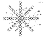
図3は、一実施形態に係るレーザ超音波計測方法における対象物のレーザ照射点の位置の一例を示す底面図である。ここでは、平板状の対象物20の第1の表面21が下向き、第2の表面22が上向きであるとする。前述のように、対象物20の第2の表面22上に溶融池23が形成され、その裏側すなわち底面である第1の表面21上に送信レーザ照射点42および受信レーザ照射点44をとる。
FIG. 3 is a bottom view showing an example of the position of the laser irradiation point of the object in the laser ultrasonic measurement method according to the embodiment. Here, it is assumed that the
溶融池23の固液界面25は、通常、下に凸の半球状に近い形状をなす。そこで、この固液界面25の3次元的な形状を的確に把握するために、溶融池23の中心位置の真下の位置を中心として、この中心を通る各放射方向線それぞれの上に複数の送信レーザ照射点42を取る。また、各放射方向線それぞれの上に1個の受信レーザ照射点44を取る。ここでは、各放射方向に並べられた複数の送信レーザ照射点42を放射方向列60と呼ぶ。各放射方向列60の最も内側の送信レーザ照射点42は溶融池23の外周よりも内側にあり、各放射方向列60の最も外側の送信レーザ照射点42は溶融池23の外周よりも外側にあるように設定する。
The solid-
溶融池23の中心位置は、溶接トーチ12(図1)の真下の位置として設定することができる。また、溶融池23の大きさは、過去の経験値などに基づいて推測することができる。
The center position of the
図3の例では、各放射方向列60に5個の送信レーザ照射点42が並べられているが、この個数は2以上であればいくつでもよい。また、図3の例では、放射方向列60が45度間隔で8本が設定されているが、各放射方向列60の数も、2以上であればいくつでもよい。ただし、放射方向列60同士の周方向の間隔は、一般には等間隔が好ましい。また、各放射方向列60の中の送信レーザ照射点42同士の間隔も、一般には等間隔が好ましい。
In the example of FIG. 3, five transmission laser irradiation points 42 are arranged in each
図3に示すように、溶融池23の中心位置の真下の位置を中心として、各放射方向列60よりも中心近くに、円環状に複数の送信レーザ照射点42が並べられ、中心位置に1個の受信レーザ照射点44が設定されている。ここでは、円環状に並べられた複数の送信レーザ照射点42を円環状列61と呼ぶ。円環状列61は溶融池23の外周よりも内側にあるように設定する。
As shown in FIG. 3, a plurality of transmission laser irradiation points 42 are arranged in an annular shape near the center of each
各放射方向列60に対応する受信レーザ照射点44の位置は、図3の例では外側から2番目と3番目の送信レーザ照射点42の間に位置しているが、これに限定されるものではなく、たとえば最外周の送信レーザ照射点42のさらに外側に位置してもよい。
In the example of FIG. 3, the position of the reception
図3に示すように、各放射方向列60について、受信レーザ照射点44を当該放射方向列60と同じ放射方向線上に配置するのが好ましいが、その放射方向線に近い位置であれば必ずしも放射方向線上でなくてもよい。ただし、当該放射方向列60の放射方向線に近い位置であることが好ましく、特に、隣接する他の放射方向列60よりも近い位置であることが好ましい。
As shown in FIG. 3, for each
送信レーザ照射点42では、送信用パルスレーザ光41の照射を受けて、アブレーションまたは熱歪により励起されて、対象物20内を伝播する超音波が発生する。このとき、特にアブレーションモードでは、送信レーザ照射点42に照射痕が残り、その位置に受信用レーザ光43を照射すると受信用レーザ光43の反射率が下がり、干渉計測をするために必要な受光量が得られなくなる場合がある。そのため、特にアブレーションモードを用いる場合は、送信レーザ照射点42と受信レーザ照射点44とは、重ならないようにするのが好ましい。
At the transmission
図4は、一実施形態に係るレーザ超音波計測方法における溶融池周辺部の固液界面の画像化領域を示す模式的立断面図である。図5は、図4の画像化領域を示す模式的斜視図である。 FIG. 4 is a schematic sectional elevation view showing an imaging region of a solid-liquid interface around the molten pool in the laser ultrasonic measurement method according to the embodiment. FIG. 5 is a schematic perspective view showing the imaging region of FIG.
図4および図5に示すように、一つの放射方向列60の複数の送信レーザ照射点42に送信用パルスレーザ光41を照射し、それらに対応する1個の受信レーザ照射点44に受信用レーザ光43を照射する。ただし、複数の送信レーザ照射点42に送信用パルスレーザ光41を照射するのは同時ではなく、時間をずらして走査する。
As shown in FIG. 4 and FIG. 5, a plurality of transmission laser irradiation points 42 in one
以上説明した送信レーザ照射点42および受信レーザ照射点44の移動は、送信レーザ移動機構37および受信レーザ移動機構38などにより行われる。送信レーザ光源30、受信レーザ光源32、送信レーザ移動機構37および受信レーザ移動機構38や、それらに合わせたデータ解析機構35および画像化装置36などの動作は、計測制御部39により自動的に制御される。
The movement of the transmission
以上の手順により、この放射方向列60に沿う固液界面25の位置を計測できる。これにより、一つの放射方向列60に沿う固液界面25を画像化領域62として表示することができる。
With the above procedure, the position of the solid-
送信レーザ照射点42および受信レーザ照射点44の移動(走査)の方向や順番は任意であり、たとえば、放射方向列60についていえば、送信レーザ照射点42を各放射方向列60の中心点に近い位置から中心点から遠い方向に移動しても、逆に、中心点から遠い位置から中心点に近い位置に移動してもよい。
The direction and order of movement (scanning) of the transmission
複数の放射方向列60について、同様に固液界面25を画像化領域62として表示することができるので、全体として固液界面25の3次元的(立体的)な形状および大きさを表示することができる。
Since the solid-
図6は、一実施形態に係るレーザ超音波計測方法における溶融池中央部の固液界面の画像化領域を示す模式的立断面図である。図7は、図6の画像化領域を示す模式的斜視図である。 FIG. 6 is a schematic sectional elevation view showing an imaging region of a solid-liquid interface at the center of the molten pool in the laser ultrasonic measurement method according to the embodiment. FIG. 7 is a schematic perspective view showing the imaging region of FIG.
図6および図7に示すように、円環状列61の複数の送信レーザ照射点42に送信用パルスレーザ光41を照射し、それらに対応する1個の受信レーザ照射点44に受信用レーザ光43を照射することにより、この円環状列61に沿う固液界面25の位置を計測できる。これにより、円環状列61に沿う固液界面25を画像化領域63として表示することができる。
As shown in FIGS. 6 and 7, a plurality of transmission laser irradiation points 42 in the
複数の放射方向列60および1個の円環状列61に沿う固液界面25をつなぎ合わせることにより、全体として固液界面25の3次元的(立体的)な形状および大きさを表示することができる。
By connecting the solid-
上述のとおり、温度センサ51が対象物20に取り付けられており、対象物20の内部の温度を表す信号がデータ解析機構35に送られる。一般に、対象物20の内部の温度に応じて、この対象物20内を伝播する超音波の速度が変化する。データ解析機構35で、この温度変化による超音波速度の変化を加味して、補正することにより、固液界面25の3次元的な形状および大きさをより正確に求めることができる。
As described above, the
さらに、データ解析機構35から得られた溶融池23の形状および大きさの信号を溶接制御部13に送り、それにより、溶接機11を制御して溶接条件を変更することができる。
Furthermore, a signal of the shape and size of the
図3に示すすべての送信レーザ照射点42および受信レーザ照射点44のレーザ照射を一通り終了する時間を1移動周期とする。画像化装置36による画像化の更新の周期である表示周期としては、たとえば、1移動周期を1表示周期と同じとすることができる。他の例としては、1表示周期を1移動周期よりも短くして、たとえば、図3に示す各放射方向列60または円環状列61でのレーザ照射完了の都度、その部分のみの表示内容更新をすることもできる。さらに他の例として、各送信レーザ照射点42ごとのデータに基いて1点ごとの表示内容更新をすることもできる。
A period for completing the laser irradiation of all the transmission laser irradiation points 42 and the reception laser irradiation points 44 shown in FIG. As a display cycle that is a cycle for updating imaging by the
上記説明では、各放射方向列60および円環状列61で、受信レーザ照射点44を1個として固定照射点とし、送信レーザ照射点42を複数個として移動照射点とした。他の例として、これらの関係を逆にして、各放射方向列60および円環状列61で、受信レーザ照射点44を複数個として移動照射点とし、送信レーザ照射点42を1個として固定照射点としてもよい。ただし、この場合には、送信用パルスレーザ光41の照射を、照射痕が残るアブレーションモードでの照射とせずに熱歪モードでの照射とするのが好ましい。
In the above description, in each of the
また、上記説明では、対象物相対移動装置15によって対象物20が移動するものとした。他の例として、対象物20が固定されていて、溶接トーチ12、送信光学機構31や受信光学機構33が一体として対象物20に対して相対的に移動するように構成してもよい。
In the above description, the
また、上記説明では、図3に示すように、各放射方向列60は互いに同じ長さであるとした。これは、溶融池23の外形が円形である場合に特に適している。しかし、たとえば、溶融池23が、溶接線16に沿って下流側に延びている場合は、その延びている方向の放射方向列60を特に長くすることにより、溶融池23の形状および大きさをより正確に計測することができる。
In the above description, as shown in FIG. 3, the
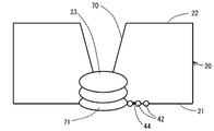
図8は、本発明の一実施形態に係るレーザ超音波計測方法において突き合わせ溶接の場合の対象物のレーザ照射点の位置の一例を示す立断面図である。図8に示すように、開先70や裏波71を伴う溶接の場合は、溶接トーチ12(図1参照)の真下に送信レーザ照射点42や受信レーザ照射点44を取ることが困難である。その場合は、図3に示す円環状列61のレーザ照射は行わず、放射方向列60のみのレーザ照射を行えばよい。この場合に、図8では、溶接トーチ12の真下の中心点から見て同じ方向に送信レーザ照射点42と受信レーザ照射点44を取る。
FIG. 8 is an elevational sectional view showing an example of the position of the laser irradiation point of the object in the case of butt welding in the laser ultrasonic measurement method according to one embodiment of the present invention. As shown in FIG. 8, in the case of welding with a
図9は、本発明の一実施形態に係るレーザ超音波計測方法において突き合わせ溶接の場合の対象物のレーザ照射点の位置の、図8とは異なる一例を示す立断面図である。図9の場合は、図8の場合の変形例であって、溶接トーチ12の真下の中心点から見て送信レーザ照射点42と受信レーザ照射点44を反対側の位置に取る。
FIG. 9 is an elevational sectional view showing an example different from FIG. 8 of the position of the laser irradiation point of the object in the case of butt welding in the laser ultrasonic measurement method according to one embodiment of the present invention. The case of FIG. 9 is a modification of the case of FIG. 8, and the transmission
以上、本発明のいくつかの実施形態を説明したが、これらの実施形態は、例として提示したものであり、発明の範囲を限定することは意図していない。これら実施形態は、その他の様々な形態で実施されることが可能であり、発明の要旨を逸脱しない範囲で、種々の省略、置き換え、変更を行うことができる。これら実施形態やその変形は、発明の範囲や要旨に含まれると同様に、特許請求の範囲に記載された発明とその均等の範囲に含まれるものである。 As mentioned above, although some embodiment of this invention was described, these embodiment is shown as an example and is not intending limiting the range of invention. These embodiments can be implemented in various other forms, and various omissions, replacements, and changes can be made without departing from the spirit of the invention. These embodiments and their modifications are included in the scope and gist of the invention, and are also included in the invention described in the claims and the equivalents thereof.
10:溶接装置、 11:溶接機、 12:溶接トーチ、 13:溶接制御部、 14:レーザ超音波計測装置、 15:対象物相対移動装置、 16:溶接線、 20:対象物、 21:第1の表面、 22:第2の表面、 23:溶融池(液相部)、 24:固相部、 25:固液界面、 30:送信レーザ光源、 31:送信光学機構、 32:受信レーザ光源、 33:受信光学機構、 34:干渉計、 35:データ解析機構、 36:画像化装置、 37:送信レーザ移動機構、 38:受信レーザ移動機構、 39:計測制御部、 40:超音波、 41:送信用パルスレーザ光、 42:送信レーザ照射点、 43:受信用レーザ光、 44:受信レーザ照射点、 50:温度計、 51:温度センサ、 52:温度計本体、 60:放射方向列、 61:円環状列、 62:画像化領域、 63:画像化領域、 70:開先、 71:裏波 10: Welding device, 11: Welding machine, 12: Welding torch, 13: Welding control unit, 14: Laser ultrasonic measuring device, 15: Object relative movement device, 16: Welding line, 20: Object, 21: No. 1 surface 22: second surface 23: molten pool (liquid phase part) 24: solid phase part 25: solid-liquid interface 30: transmission laser light source 31: transmission optical mechanism 32: reception laser light source 33: reception optical mechanism, 34: interferometer, 35: data analysis mechanism, 36: imaging device, 37: transmission laser movement mechanism, 38: reception laser movement mechanism, 39: measurement control unit, 40: ultrasonic wave, 41 : Transmission pulse laser beam, 42: Transmission laser irradiation point, 43: Reception laser beam, 44: Reception laser irradiation point, 50: Thermometer, 51: Temperature sensor, 52: Thermometer body, 60: Radiation direction column 61: an annular column, 62: imaging region, 63: imaging region, 70: groove, 71: penetration
Claims (6)
超音波を励起する送信用パルスレーザ光を発生する送信レーザ光源と、
前記送信レーザ光源で発生した前記送信用パルスレーザ光を前記第1の表面上の送信レーザ照射点に導く送信光学機構と、
受信用レーザ光を発生する受信レーザ光源と、
前記受信レーザ光源で発生した前記受信用レーザ光を前記第1の表面上の受信レーザ照射点に照射して反射した前記受信用レーザ光を集光する受信光学機構と、
前記受信光学機構で集光した前記受信レーザ光に基づいて得られた超音波信号を解析して前記固液界面の位置を求めるデータ解析機構と、
前記送信レーザ照射点を前記第1の表面に沿って動かす送信レーザ移動機構と、
前記受信レーザ照射点を前記第1の表面に沿って動かす受信レーザ移動機構と、
前記送信レーザ光源、前記受信レーザ光源、前記送信レーザ移動機構および前記受信レーザ移動機構を制御する計測制御部と、
を有し、
前記計測制御部は、前記送信レーザ照射点および前記受信レーザ照射点のうちの一方を固定照射点とし、他方を移動照射点とし、前記第1の表面上の所定の中心点を中心とする複数の放射方向線のそれぞれに沿う複数の前記移動照射点と、前記複数の放射方向線のそれぞれに対し定めた1箇所の前記固定照射点に前記送信用パルスレーザ光または前記受信用レーザ光を照射するように構成されていること、
を特徴とするレーザ超音波計測装置。 A solid phase portion is formed in contact with the first surface, a liquid phase portion is formed in contact with a part of the second surface opposite to the first surface, and the solid phase portion and the liquid phase portion A laser ultrasonic measurement device for measuring the position of the solid-liquid interface of an object in which a solid-liquid interface is formed,
A transmission laser light source for generating a transmission pulse laser beam for exciting ultrasonic waves;
A transmission optical mechanism for guiding the transmission pulse laser beam generated by the transmission laser light source to a transmission laser irradiation point on the first surface;
A receiving laser light source for generating a receiving laser beam;
A receiving optical mechanism for condensing the receiving laser beam reflected by irradiating the receiving laser beam on the first surface with the receiving laser beam generated by the receiving laser light source;
A data analysis mechanism for analyzing the ultrasonic signal obtained based on the received laser light collected by the reception optical mechanism to determine the position of the solid-liquid interface;
A transmission laser moving mechanism for moving the transmission laser irradiation point along the first surface;
A receiving laser moving mechanism for moving the receiving laser irradiation point along the first surface;
A measurement control unit for controlling the transmission laser light source, the reception laser light source, the transmission laser moving mechanism, and the reception laser moving mechanism;
Have
The measurement control unit has one of the transmission laser irradiation point and the reception laser irradiation point as a fixed irradiation point, the other as a moving irradiation point, and a plurality of centers around a predetermined center point on the first surface. A plurality of the moving irradiation points along each of the radiation direction lines and one fixed irradiation point defined for each of the plurality of radiation direction lines is irradiated with the pulse laser beam for transmission or the laser beam for reception Being configured to,
A laser ultrasonic measurement device characterized by the above.
前記対象物の前記第2の表面を溶接して前記液相部として溶融池を形成する溶接トーチと、
前記溶接トーチの溶接条件を制御する溶接制御部と、
を備えた溶接装置であって、
前記溶接制御部は、前記レーザ超音波計測装置から得られた前記固液界面の位置に基づいて前記溶接条件を制御するように構成されていることを特徴とする溶接装置。 The laser ultrasonic measurement device according to any one of claims 1 to 3,
A welding torch that welds the second surface of the object to form a molten pool as the liquid phase portion;
A welding control unit for controlling welding conditions of the welding torch;
A welding apparatus comprising:
The welding apparatus is configured to control the welding condition based on the position of the solid-liquid interface obtained from the laser ultrasonic measurement device.
送信用パルスレーザ光を発生させて前記第1の表面上の送信レーザ照射点に照射する送信レーザ照射ステップと、
受信用レーザ光を前記第1の表面上の受信レーザ照射点に照射して反射した前記受信用レーザ光を集光する受信レーザ集光ステップと、
前記受信レーザ集光ステップで集光した前記受信用レーザ光に基づいて得られた超音波信号を解析して前記固液界面の位置を求めるデータ解析ステップと、
を有し、
前記送信レーザ照射ステップおよび前記受信レーザ集光ステップにおいて、前記送信レーザ照射点および前記受信レーザ照射点のうちの一方を固定照射点とし、他方を移動照射点とし、前記第1の表面上の所定の中心点を中心とする複数の放射方向線のそれぞれに沿う複数の前記移動照射点と、前記複数の放射方向線のそれぞれに対して定めた1箇所の前記固定照射点に前記送信用パルスレーザ光または前記受信用レーザ光を照射すること、
を特徴とするレーザ超音波計測方法。 The solid phase portion is formed by forming a liquid phase portion on a part of the second surface of the object, the solid phase portion including the first surface and the second surface opposite to the first surface. A solid-liquid interface forming step for forming a solid-liquid interface between the liquid phase part and the liquid phase part;
A transmission laser irradiation step of generating a transmission pulse laser beam and irradiating the transmission laser irradiation point on the first surface;
A receiving laser condensing step of condensing the receiving laser beam reflected by irradiating the receiving laser beam on the first surface with the receiving laser beam;
A data analysis step of analyzing the ultrasonic signal obtained based on the reception laser beam condensed in the reception laser condensing step to determine the position of the solid-liquid interface;
Have
In the transmission laser irradiation step and the reception laser condensing step, one of the transmission laser irradiation point and the reception laser irradiation point is set as a fixed irradiation point, and the other is set as a moving irradiation point. The transmitting pulse laser is applied to the plurality of moving irradiation points along each of the plurality of radiation direction lines centered on the center point and one fixed irradiation point defined for each of the plurality of radiation direction lines. Irradiating light or the receiving laser beam,
A laser ultrasonic measurement method characterized by the above.
Priority Applications (1)
| Application Number | Priority Date | Filing Date | Title |
|---|---|---|---|
| JP2016063290A JP6559604B2 (en) | 2016-03-28 | 2016-03-28 | Laser ultrasonic measuring apparatus, laser ultrasonic measuring method, welding apparatus and welding method |
Applications Claiming Priority (1)
| Application Number | Priority Date | Filing Date | Title |
|---|---|---|---|
| JP2016063290A JP6559604B2 (en) | 2016-03-28 | 2016-03-28 | Laser ultrasonic measuring apparatus, laser ultrasonic measuring method, welding apparatus and welding method |
Publications (2)
| Publication Number | Publication Date |
|---|---|
| JP2017181048A true JP2017181048A (en) | 2017-10-05 |
| JP6559604B2 JP6559604B2 (en) | 2019-08-14 |
Family
ID=60005840
Family Applications (1)
| Application Number | Title | Priority Date | Filing Date |
|---|---|---|---|
| JP2016063290A Active JP6559604B2 (en) | 2016-03-28 | 2016-03-28 | Laser ultrasonic measuring apparatus, laser ultrasonic measuring method, welding apparatus and welding method |
Country Status (1)
| Country | Link |
|---|---|
| JP (1) | JP6559604B2 (en) |
Cited By (2)
| Publication number | Priority date | Publication date | Assignee | Title |
|---|---|---|---|---|
| CN109387568A (en) * | 2018-12-21 | 2019-02-26 | 西安增材制造国家研究院有限公司 | A kind of laser ultrasonic detection device and increasing material manufacturing, detection integrated equipment |
| CN109991311A (en) * | 2019-04-09 | 2019-07-09 | 中国十七冶集团有限公司 | A kind of workshop column reinforcing method and its detection device |
-
2016
- 2016-03-28 JP JP2016063290A patent/JP6559604B2/en active Active
Cited By (3)
| Publication number | Priority date | Publication date | Assignee | Title |
|---|---|---|---|---|
| CN109387568A (en) * | 2018-12-21 | 2019-02-26 | 西安增材制造国家研究院有限公司 | A kind of laser ultrasonic detection device and increasing material manufacturing, detection integrated equipment |
| CN109991311A (en) * | 2019-04-09 | 2019-07-09 | 中国十七冶集团有限公司 | A kind of workshop column reinforcing method and its detection device |
| CN109991311B (en) * | 2019-04-09 | 2021-06-11 | 中国十七冶集团有限公司 | Factory building column reinforcing method and weld joint detection device thereof |
Also Published As
| Publication number | Publication date |
|---|---|
| JP6559604B2 (en) | 2019-08-14 |
Similar Documents
| Publication | Publication Date | Title |
|---|---|---|
| JP6754439B2 (en) | Methods and equipment for monitoring joint seams during laser beam junctions | |
| US11229973B2 (en) | Detection of hot cracks in laser welding | |
| JP6808027B2 (en) | A method for measuring welding depth optically | |
| CN102323216B (en) | Welding inspection method and apparatus thereof | |
| JP6220718B2 (en) | Laser welding quality determination method and laser welding quality determination device | |
| JP5947741B2 (en) | Welded part inspection device and inspection method | |
| JP6541778B2 (en) | Welding apparatus and welding quality inspection method | |
| JP2009222408A (en) | Ultrasonic flaw detection method, ultrasonic flaw detecting device, and production method for seam-welded pipe | |
| CN105073330A (en) | Welding portion inspection device and inspection method therefor | |
| WO2021182032A1 (en) | Defect detection method, defect detection device, and shaping device | |
| JP6559604B2 (en) | Laser ultrasonic measuring apparatus, laser ultrasonic measuring method, welding apparatus and welding method | |
| US6849821B2 (en) | Laser welding head-controlling system, a laser welding head and a method for controlling a laser welding head | |
| CN113195149A (en) | Method and device for monitoring a welding process for welding glass workpieces | |
| JP5292012B2 (en) | Ultrasonic inspection equipment | |
| CN104923912A (en) | Laser welding inspection apparatus and laser welding inspection method | |
| US20230330784A1 (en) | Weld inspection device, welding system, and weld inspection method | |
| JP6385763B2 (en) | Laser welding apparatus and laser welding method | |
| JPH081361A (en) | Laser beam cladding device and its method for controlling position of irradiation | |
| JP2017116285A (en) | Laser ultrasonic inspection method, joining method, laser ultrasonic inspection device, and joining device | |
| EP3315238A1 (en) | Method of and welding process control system for real-time tracking of the position of the welding torch by the use of fiber bragg grating based optical sensors | |
| RU2523406C1 (en) | Welding of large-diameter pipes by laser beam | |
| JP2682390B2 (en) | Ultrasonic flaw detector for welds | |
| JP2014024068A (en) | Bead inspection method in laser welding and laser welding method | |
| CN113714635A (en) | Laser processing apparatus | |
| Chen et al. | Dynamic evolution of the weld pool reflection during weld penetration development |
Legal Events
| Date | Code | Title | Description |
|---|---|---|---|
| A711 | Notification of change in applicant |
Free format text: JAPANESE INTERMEDIATE CODE: A711 Effective date: 20171201 Free format text: JAPANESE INTERMEDIATE CODE: A712 Effective date: 20171201 |
|
| A621 | Written request for application examination |
Free format text: JAPANESE INTERMEDIATE CODE: A621 Effective date: 20180820 |
|
| A977 | Report on retrieval |
Free format text: JAPANESE INTERMEDIATE CODE: A971007 Effective date: 20190515 |
|
| TRDD | Decision of grant or rejection written | ||
| A01 | Written decision to grant a patent or to grant a registration (utility model) |
Free format text: JAPANESE INTERMEDIATE CODE: A01 Effective date: 20190618 |
|
| A61 | First payment of annual fees (during grant procedure) |
Free format text: JAPANESE INTERMEDIATE CODE: A61 Effective date: 20190717 |
|
| R150 | Certificate of patent or registration of utility model |
Ref document number: 6559604 Country of ref document: JP Free format text: JAPANESE INTERMEDIATE CODE: R150 |