JP2017180941A - Air conditioner - Google Patents
Air conditioner Download PDFInfo
- Publication number
- JP2017180941A JP2017180941A JP2016067973A JP2016067973A JP2017180941A JP 2017180941 A JP2017180941 A JP 2017180941A JP 2016067973 A JP2016067973 A JP 2016067973A JP 2016067973 A JP2016067973 A JP 2016067973A JP 2017180941 A JP2017180941 A JP 2017180941A
- Authority
- JP
- Japan
- Prior art keywords
- wind speed
- air
- unit
- temperature
- sensor unit
- Prior art date
- Legal status (The legal status is an assumption and is not a legal conclusion. Google has not performed a legal analysis and makes no representation as to the accuracy of the status listed.)
- Pending
Links
Images


Abstract
Description
本発明は、空気調和機に関するものである。 The present invention relates to an air conditioner.
ユーザが操作可能な「暑いときスイッチ」や「寒いときスイッチ」を設け、これらのスイッチが操作されたときに、室内機で検出した温度や湿度を基準にして、設定温度や湿度を調節するものがある。 A “hot switch” or “cold switch” that can be operated by the user is provided, and when these switches are operated, the set temperature and humidity are adjusted based on the temperature and humidity detected by the indoor unit. There is.
人にとっての快適さは風速によっても左右されるため、単に暑いか寒いかだけでは、それが真に快適かどうかを判断できない。特に、暖房時に空気調和機から吹出される風がユーザに当たると、ユーザにとって隙間風が当たったようなドラフト感となり、風速の変動が大きいほど、不快に感じさせる要因の一つとなりやすいため、従来の空気調和機ではユーザにとって快適な環境を実現することが難しい。
本発明の課題は、ユーザにとって快適な環境を実現する空気調和機を提供することである。
Because comfort for humans depends on wind speed, it is not possible to judge whether it is truly comfortable simply by whether it is hot or cold. In particular, when the air blown from the air conditioner hits the user during heating, it becomes a draft feeling as if the gap air was hit by the user. With this air conditioner, it is difficult to realize a comfortable environment for the user.
The subject of this invention is providing the air conditioner which implement | achieves a comfortable environment for a user.
本発明の一態様に係る空気調和機は、室内の空気調和を行なう室内機と、室内機とは別に設けられ、室内の温度及び風速を検出するセンサユニットと、センサユニットで検出した温度情報及び風速情報を、室内機に送信する送信部と、を備え、室内機は、暖房運転時に、センサユニットで検出する風速の変化量が所定の値以下となるように、風量を制御する。 An air conditioner according to an aspect of the present invention includes an indoor unit that performs indoor air conditioning, a sensor unit that is provided separately from the indoor unit, detects indoor temperature and wind speed, temperature information detected by the sensor unit, and A transmission unit that transmits wind speed information to the indoor unit, and the indoor unit controls the air volume so that the amount of change in the wind speed detected by the sensor unit is equal to or less than a predetermined value during the heating operation.
本発明によれば、暖房運転時に、センサユニットで室内の温度及び風速を検出し、風速の変化が少なくなるように、風量を制御することにより、ユーザにとって快適な環境を実現する空気調和機を提供することができる。 According to the present invention, an air conditioner that realizes a comfortable environment for a user by detecting the indoor temperature and wind speed with a sensor unit during heating operation and controlling the air volume so that the change in the wind speed is reduced. Can be provided.
以下、本発明の実施形態を図面に基づいて説明する。なお、各図面は模式的なものであって、現実のものとは異なる場合がある。また、以下の実施形態は、本発明の技術的思想を具体化するための装置や方法を例示するものであり、構成を下記のものに特定するものでない。すなわち、本発明の技術的思想は、特許請求の範囲に記載された技術的範囲内において、種々の変更を加えることができる。 Hereinafter, embodiments of the present invention will be described with reference to the drawings. Each drawing is schematic and may be different from the actual one. Further, the following embodiments exemplify apparatuses and methods for embodying the technical idea of the present invention, and the configuration is not specified as follows. That is, the technical idea of the present invention can be variously modified within the technical scope described in the claims.
《構成》
図1は、空気調和機の構成図である。
空気調和機11は、室内12の壁面に取り付けられた室内機13と、戸外に設置された室外機14と、を備える。空気調和機11は、リモートコントローラ(以下、単にリモコンと称す)15を介した無線通信により、ユーザによって遠隔操作される。
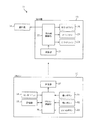
図2は、空気調和機の機能ブロック図である。
室内機13は、受信部21と、室内機制御部22と、メインファン23と、左サイドファン24と、右サイドファン25と、を備える。
受信部21は、リモコン15からの各種信号を受信する。
室内機制御部22は、リモコン15からの各種信号を受け、室外機14、メインファン23、左サイドファン24、及び右サイドファン25を駆動制御する。ここで、メインファン23が「第一のファン」に対応し、左サイドファン24、及び右サイドファンが「第二のファン」に対応する。
"Constitution"
FIG. 1 is a configuration diagram of an air conditioner.
The
FIG. 2 is a functional block diagram of the air conditioner.
The
The
The indoor
室内機13と室外機14との間には、冷媒回路が形成されており、この冷媒回路を循環する冷媒により熱エネルギーの交換が行われ、室内機13から冷気や暖気が室内12へ供給される。室内機制御部22は、室外機14のコンプレッサーや四方弁を駆動制御することにより、冷房/暖房の切り換えや室内機13から吹き出される冷気や暖気の温度をコントロールする。
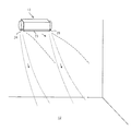
図3及び図4は、室内機のイメージ図である。
メインファン23は、室内機13に設けられ、冷媒回路を経て供給される冷気や暖気を吹き出す。つまり、冷媒と熱交換した空気を送風する。メインファン23により吹き出された空気は、筐体の吹出口に設けられた上下風向板、及び左右風向板の各々の風向板の向きによって、吹き出し方向を調整できる。
A refrigerant circuit is formed between the
3 and 4 are image diagrams of the indoor unit.
The
左サイドファン24は、室内機13本体における一方の側面に設けられ、右サイドファン25は、他方の側面に設けられ、何れも室内温度の空気のみを吹き出す。つまり冷媒と熱交換していない空気を送風する。左サイドファン24、及び右サイドファン25は、夫々、同一の軸周りに回動可能で、自らの回動位置、及び筐体内に設けられた風向板の向きによって、吹き出し方向を調整できる。尚、室内機13はメインファン23、左サイドファン24及び右サイドファン25の回転軸が水平になるように室内12に設置される。
The
図3は、冷房運転の一例を示している。ここでは、破線で示すように、メインファン23により吹き出された冷気は水平方向に吹き出し、点線で示すように、左サイドファン24、及び右サイドファン25による送風は斜め下方向に吹き出している。このようにして、冷気が直接身体に当たらないようにしつつも、快適な温度の送風をユーザが浴びられるようにすることで、控えめな冷房運転でも自然な涼しさを感じることができる。
図4は、暖房運転の一例を示している。ここでは、破線で示すように、メインファン23により吹き出された暖気は真下に吹き出し、点線で示すように、左サイドファン24、及び右サイドファン25による送風は斜め下方向に吹き出している。このようにして、暖気の吹き上がりを送風によって押さえ込むことにより、暖気が室内12の奥まで広がり、床面全体を暖めることができる。
FIG. 3 shows an example of the cooling operation. Here, as shown by the broken line, the cold air blown out by the
FIG. 4 shows an example of the heating operation. Here, as indicated by the broken line, the warm air blown out by the
リモコン15は、持ち運び可能であり、図2に示すように、暑いボタン31と、寒いボタン32と、いいねボタン33(満足操作部)と、センサユニット34と、記憶部35と、リモコン制御部36と、送信部37と、を備える。
暑いボタン31は、ユーザが暑いと感じているときに操作するボタンである。
寒いボタン32は、ユーザが寒いと感じているときに操作するボタンである。
いいねボタン33は、ユーザが温度、湿度、及び風速について快適であると感じているとき、つまり室内12の空気調和環境に満足しているときに操作するボタンである。
The
The
The
The
センサユニット34は、リモコン周囲の温度を検出する温度センサ、及びリモコン周囲の風速を検出する風速センサを有する。温度センサは、温度変化に伴って電気抵抗が変化するサーミスタを用いる。風速センサは、一対のサーミスタを用いて風速(気流)を検出する。
記憶部35は、ユーザによってなされた運転設定、つまり温度設定、風量設定、及び風向設定等、各種情報を記憶する。
リモコン制御部36は、各ボタンからのボタン信号、及びセンサユニット34からのセンサ信号を受け、送信部37へ送る。具体的には、暑いボタン31が押されたときのボタン信号、寒いボタン32が押されたときのボタン信号、いいねボタン33が押されたときのボタン信号(満足信号)、センサユニット34で検出した温度信号、風速信号である。
各種信号を受けた送信部37は、各種信号を室内機13へ送信する。また、送信部37は、所定の間隔で随時センサ信号を室内機13へ送信している。
The
The memory |
The remote
Upon receiving the various signals, the transmission unit 37 transmits the various signals to the
次に、リモコン制御部36で実行する風速検出処理について説明する。
ここでは、本発明に係る処理を中心に説明しており、冷媒回路の制御等の一般的な処理は省略する。
図5は、暖房運転時の風速検出処理を示すフローチャートである。
風速検出処理は、ユーザが室内機13に対して運転開始を指示する操作が行われたら開始され、以後、所定の演算周期に従って繰り返し実行される。
ステップS101では、センサユニット34の温度センサで検出した温度tが、設定されている設定温度tsに到達したか否かを判定する。ここで、温度tが設定温度tsに到達していないときには(S101−No)、ステップS103に移行する。一方、温度tが設定温度tsに到達しているときには(S101−Yes)、温度tがひとたび設定温度tsに到達してから、予め定めた時間(例えば数十分)が経過したか否かを判定する(S102)。予め定めた時間(例えば数十分)が経過していれば(S102−Yes)、ステップS104へ移行し、経過していなければ(S102−No)、ステップS103へ移行する。
Next, the wind speed detection process executed by the
Here, the processing according to the present invention is mainly described, and general processing such as control of the refrigerant circuit is omitted.
FIG. 5 is a flowchart showing wind speed detection processing during heating operation.
The wind speed detection process is started when the user performs an operation for instructing the
In step S101, it is determined whether or not the temperature t detected by the temperature sensor of the
ステップS103では、いいねボタン33が操作されたか否かを判定する。ここで、いいねボタン33が操作されていないときには(S103−No)、そのままステップS101に戻る。一方、いいねボタン33が操作されたときには(S103−Yes)、ステップS104に移行する。
ステップS104では、予め定めた期間T(例えば2〜3分)における風速uの推移を分析する。尚、センサユニット34は随時風速uを検出しており、検出結果を時系列で記憶部35に記憶させている。
続くステップS105では、送信部37を介して、いいねボタン33の操作情報、温度情報、及び風速情報を、室内機13へ送信し、ステップS101に戻る。
上記が風速検出処理である。
In step S103, it is determined whether the
In step S104, the transition of the wind speed u in a predetermined period T (for example, 2 to 3 minutes) is analyzed. The
In subsequent step S105, the operation information, temperature information, and wind speed information of the
The above is the wind speed detection process.
次に、室内機制御部22で実行する運転制御処理について説明する。
ここでは、本発明に係る処理を中心に説明しており、冷媒回路の制御等の一般的な処理は省略する。
図6は、暖房運転時の運転制御処理を示すフローチャートである。
運転制御処理は、ユーザが室内機13に対して運転開始を指示する操作が行われたら開始され、以後、所定の演算周期に従って繰り返し実行される。
ステップS111では、いいねボタン33が操作されたか否かを判定する。ここで、いいねボタン33が操作されていないときには(S111−No)、ステップS112に移行する。一方、いいねボタン33が操作されたときには(S111−Yes)、ステップS116に移行する。
Next, the operation control process executed by the indoor
Here, the processing according to the present invention is mainly described, and general processing such as control of the refrigerant circuit is omitted.
FIG. 6 is a flowchart showing an operation control process during the heating operation.
The operation control process is started when the user performs an operation for instructing the
In step S111, it is determined whether the
ステップS112では、現在の運転設定を維持する。すなわち、記憶部35に記憶されている現在の温度設定、風量設定、及び風向設定を維持したままにする。
続くステップS113では、風速情報を受信したか否かを判定する。ここで、風速情報を受信しているときには(S113−Yes)、ステップS114に移行する。一方、風速情報を受信していないときには、そのままステップS111に戻る。
ステップS114では、暖房運転であるか否かを判定する。ここで、暖房運転であるときには(S114−Yes)、ステップS115に移行する。一方、暖房運転ではない、つまり冷房運転、除湿運転、送風運転の何れかであるときには、そのままステップS111に戻る。
In step S112, the current operation setting is maintained. That is, the current temperature setting, air volume setting, and wind direction setting stored in the
In a succeeding step S113, it is determined whether or not wind speed information is received. If the wind speed information is received (S113-Yes), the process proceeds to step S114. On the other hand, when the wind speed information is not received, the process returns to step S111 as it is.
In step S114, it is determined whether it is heating operation. Here, when it is heating operation (S114-Yes), it transfers to step S115. On the other hand, if it is not the heating operation, that is, if it is any of the cooling operation, the dehumidifying operation, and the air blowing operation, the process directly returns to step S111.
ステップS115では、センサユニット34で検出する風速uの変化量が所定の値以下となるように、風量制御を行なってからステップS111に戻る。具体的には、風速uの変化量Δuが所定値(例えば、0.5m/s)を超えた場合、風速uが増加しているのであれば、メインファン23、左サイドファン24、及び右サイドファン25の風量を所定量下げ、風速uが減少しているのであれば、メインファン23、左サイドファン24、及び右サイドファン25の風量を所定量下げる。所定量は、大きい値を設定すると風速uへの影響が大きくなってしまうため、風速uのきめ細かい調整を行うためには小さい値を設定することが好ましい。ここでは、室内12の温度tが変化しないように、温度設定やメインファン23の回転数は維持したまま、左サイドファン24、及び右サイドファン25の風量を制御する。
In step S115, the air volume control is performed so that the change amount of the wind speed u detected by the
ステップS116では、運転設定を更新してからステップS111に戻る。すなわち、いいねボタン33が操作されたときに、センサユニット34で検出された温度及び風速を検出目標温度及び検出目標風速として記憶部35に記憶し、以降、センサユニット34で検出された温度が検出目標温度のまま維持されるように、検出された風速が検出目標風速のまま維持されるように温度設定、風量設定、及び風向設定に更新する。例えば、まずリビングでユーザがいいねボタン33を操作した場合、その時にセンサユニット34で検出された温度が検出目標温度、風速が検出目標風速として記憶部に記憶される。その後、ユーザがリモコン15を携えてダイニングへ移動して、センサユニット34で検出される温度及び風速が検出目標温度及び検出目標風速から変化していた場合、温度が検出目標温度となるように、また、風速が検出目標風速となるように室内機13側の温度設定、風量設定、及び風向設定を更新する。
上記が運転制御処理である。
In step S116, the operation setting is updated, and then the process returns to step S111. That is, when the
The above is the operation control process.
《作用効果》
次に、作用効果について説明する。
人にとっての快適さは風速によっても左右されるため、単に暑いか寒いかだけでは、それが真に快適かどうかを判断できない。特に、暖房時に空気調和機から吹出される風がユーザに当たると、ユーザにとって隙間風が当たったようなドラフト感となり、風速の変動が大きいほど、不快に感じさせる要因の一つとなりやすいため、従来の空気調和機ではユーザにとって快適な環境を実現することが難しい。
<Effect>
Next, operational effects will be described.
Because comfort for humans depends on wind speed, it is not possible to judge whether it is truly comfortable simply by whether it is hot or cold. In particular, when the air blown from the air conditioner hits the user during heating, it becomes a draft feeling as if the gap air was hit by the user. With this air conditioner, it is difficult to realize a comfortable environment for the user.
そこで、本実施形態のリモコン15は、センサユニット34で、室内12の温度t及び風速uを検出し(ステップS104)、検出した温度情報及び風速情報を、送信部37が室内機13に送信する(ステップS105)。温度情報及び風速情報を受信した室内機13は、風速情報を受信したときに(ステップS113の判定が“Yes”)、暖房運転をしている場合は(ステップS114の判定が“Yes”)、センサユニット34で検出する風速の変化量が所定の値以下となるように、風量を制御する(ステップS115)。
Therefore, in the
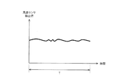
図7は、風量制御前の風速を示すグラフである。
センサユニット34で検出する風速uは、メインファン23からの送風、左サイドファン24からの送風、及び右サイドファン25からの送風が合わさったものである。一つのファンだけを用い、一定の回転数を維持させても、風速には様々な理由から乱れやムラが生じるものであり、まして複数のファンを用いると、センサユニット34で検出する風速uには、図のような変動が生じてしまう。
風量制御では、例えば、風速uの変化量Δuが所定値(例えば、0.5m/s)を超えた場合、風速uが増加しているのであれば、メインファン23、左サイドファン24、及び右サイドファン25の風量を所定量下げ、風速uが減少しているのであれば、メインファン23、左サイドファン24、及び右サイドファン25の風量を所定量下げる。
FIG. 7 is a graph showing the wind speed before the air volume control.
The wind speed u detected by the
In the air volume control, for example, when the change amount Δu of the wind speed u exceeds a predetermined value (for example, 0.5 m / s), if the wind speed u increases, the
このように、風速情報を受信する度に、メインファン23、左サイドファン24、及び右サイドファン25の風量を細かく調整してゆくことで、センサユニット34で検出する風速uの変動が低減される。
図8は、送風制御後の風速を示すグラフである。
ここでは、風量制御を何度か繰り返し実行したことで、センサユニット34で検出する風速uの変動が抑制されている様子を示している。これにより、風速変動による不快感を抑制することができる。
このように、暖房運転時に、センサユニット34で室内12風速uを検出し、風速の変化が少なくなるように、室内機13の風量を制御することにより、ユーザにとって快適な環境を実現することができる。
In this way, by adjusting the air volume of the
FIG. 8 is a graph showing the wind speed after the air blowing control.
Here, it is shown that fluctuations in the wind speed u detected by the
In this way, during the heating operation, the
また、送信部37は、所定の間隔で随時センサユニット34で検出した温度情報及び風速情報を室内機13へ送信している。しかし、センサユニット34の風速センサは、風速uを検出するに当たり、サーミスタを加熱させる必要があり、電力消費を抑制するためには、検出頻度を最小限に抑制することが望まれる。そこで、センサユニット34で風速uを検出するのは、室内12の温度tが設定温度tsに到達してからか(ステップS101の判定が“Yes”)、又はいいねボタン33が操作されたとき(ステップS103の判定が“Yes”)とする。このように、風速uの検出頻度を最小限に抑制することで、電力消費の増大を抑制することができる。
Further, the transmission unit 37 transmits temperature information and wind speed information detected by the
また、温度tが設定温度tsに到達するまでの過渡状態では、室内機13の運転も安定しておらず、室内12の気流も乱れがちである。したがって、温度tが設定温度tsに到達してから、風速uを検出することにより、室内機13の運転が安定してからのデータを検出することができる。したがって、その後の風量制御も行ないやすくなり、精度を向上させることができる。また、いいねボタン33が操作されてから、風速uを検出することにより、ユーザが快適と感じた、その時点の風速uを正確に把握することができる。
Further, in a transitional state until the temperature t reaches the set temperature ts, the operation of the
また、風量制御では、温度設定やメインファン23の回転数は維持したまま、左サイドファン24、及び右サイドファン25の風量のみを制御するようにしてもよい。これにより、室内12の温度tが変化することを抑制できる。このように、熱交換した空気を送風するメインファン23とは別に、熱交換していない空気を送風する左サイドファン24、及び右サイドファン25を備えているからこそ、室内12の温度と風速とを個別に制御することができ、ユーザにとって快適な環境を実現することができる。
Further, in the air volume control, only the air volumes of the
また、センサユニット34をリモコン15に組み込むことで、ユーザはセンサユニット34を容易に携行することができる。リモコン15は、ユーザの手が届く範囲に置かれることが多いため、ユーザ周囲の温度及び風速、つまりユーザが感じている温度及び風速を把握することができる。また、いいねボタン33を容易に操作することもできる。
そして、室内機13は、いいねボタン33が操作されていないときには(ステップS111の判定が“No”)、現在の運転設定、つまり温度設定、風量設定、及び風向設定を維持したままにする(ステップS112)。一方、いいねボタン33が操作されたときには(ステップS111の判定が“Yes”)、そのときの温度及び風速に応じて、温度設定、風量設定、及び風向設定を更新する(ステップS116)。
Further, by incorporating the
When the
このように、送信部37から送信された、いいねボタン33が操作されたときの温度及び風速を維持するように空気調和を行なうことにより、ユーザにとって快適な温度及び風速を実現することができる。また、いいねボタン33が操作されたときのセンサユニット34が検出した温度及び風速に応じて運転設定を更新することで、次回運転時に、前回運転停止直前の運転状態を引き継ぐことができる。これにより、ユーザにとっての快適さを学習し、ユーザが快適と感じた環境を、リモコン15の周辺に再現することができる。したがって、例えばリビングとダイニングが一体になっており、まずリビングでユーザがいいねボタン33を操作したとする。その後、ユーザがリモコン15を携えてダイニングへ移動すると、リビングでユーザが快適と感じた快適な環境を、ダイニングでも再現することができる。
Thus, by performing the air conditioning so as to maintain the temperature and the wind speed transmitted from the transmitting unit 37 when the
《変形例》
本実施形態では、センサユニット34で検出する風速の変化量が所定の値となるように、左サイドファン24、及び右サイドファン25の風量を制御しているが、これに限定されるものではない。風量の他にも、例えば風向を制御するようにしてもよい。このように、風量のみならず、さらに風向を制御することにより、センサユニット34で検出する風速の変化を少なくすることが一層容易になる。
<Modification>
In the present embodiment, the air volume of the
本実施形態では、センサユニット34で検出する風速の変化量が所定の値となるように、左サイドファン24、及び右サイドファン25の風量のみを制御しているが、これに限定されるものではない。目標温度としつつ目標風速となるように制御するためには、熱交換した空気の風量を制御する必要がある場合もある。この場合には、温度設定は維持したまま、センサユニット34で検出する風速の変化量が所定の値となるように、メインファン23の風量のみを制御する。これにより、ユーザにとって快適な環境を実現することができる。
以上、限られた数の実施形態を参照しながら説明したが、権利範囲はそれらに限定されるものではなく、上記の開示に基づく実施形態の改変は、当業者にとって自明のことである。
In the present embodiment, only the air volume of the
Although the present invention has been described with reference to a limited number of embodiments, the scope of rights is not limited thereto, and modifications of the embodiments based on the above disclosure are obvious to those skilled in the art.
11 空気調和機
12 室内
13 室内機
14 室外機
15 リモコン
22 室内機制御部
23 メインファン
24 左サイドファン
25 右サイドファン
31 暑いボタン
32 寒いボタン
33 いいねボタン
34 センサユニット
35 記憶部
36 リモコン制御部
37 送信部
11
Claims (6)
前記室内機とは別に設けられ、前記室内の温度及び風速を検出するセンサユニットと、
前記センサユニットで検出した温度情報及び風速情報を、前記室内機に送信する送信部と、を備え、
前記室内機は、
暖房運転時に、前記センサユニットで検出する風速の変化量が所定の値以下となるように、風量を制御することを特徴とする空気調和機。 An indoor unit that performs indoor air conditioning;
A sensor unit that is provided separately from the indoor unit and detects the temperature and wind speed of the room;
A transmission unit that transmits temperature information and wind speed information detected by the sensor unit to the indoor unit;
The indoor unit is
An air conditioner that controls an air volume so that a change amount of an air speed detected by the sensor unit is not more than a predetermined value during a heating operation.
前記室内の温度が予め設定された温度に到達してから、前記室内の風速を検出することを特徴とする請求項1に記載の空気調和機。 The sensor unit is
The air conditioner according to claim 1, wherein the air velocity in the room is detected after the temperature in the room reaches a preset temperature.
熱交換した空気を送風する第一のファンと、
熱交換していない空気を送風する第二のファンと、を備え、
前記センサユニットで検出する風速の変化量が所定の値以下となるように、前記第二のファンの送風のみを制御することを特徴とする請求項1又は2に記載の空気調和機。 The indoor unit is
A first fan that blows heat-exchanged air;
A second fan for blowing air that is not heat exchanged,
3. The air conditioner according to claim 1, wherein only air flow of the second fan is controlled so that a change amount of the wind speed detected by the sensor unit is equal to or less than a predetermined value.
熱交換した空気を送風する第一のファンと、
熱交換していない空気を送風する第二のファンと、を備え、
前記センサユニットで検出する風速の変化量が所定の値以下となるように、前記第一のファンの送風のみを制御することを特徴とする請求項1又は2に記載の空気調和機。 The indoor unit is
A first fan that blows heat-exchanged air;
A second fan for blowing air that is not heat exchanged,
3. The air conditioner according to claim 1, wherein only air flow of the first fan is controlled so that a change amount of a wind speed detected by the sensor unit is equal to or less than a predetermined value.
前記室内機の持ち運び可能なリモートコントローラに設けられることを特徴とする請求項1〜4の何れか一項に記載の空気調和機。 The sensor unit is
The air conditioner according to any one of claims 1 to 4, wherein the air conditioner is provided in a portable remote controller of the indoor unit.
前記送信部は、
前記満足操作部が操作されたときに、前記満足操作部の操作情報、並びに前記センサユニットで検出した温度情報及び風速情報を、前記室内機に送信し、
前記温度情報及び前記風速情報を受信した前記室内機は、
前記満足操作部が操作されたときに、前記センサユニットで検出した温度及び風速を維持するように空気調和を行なうことを特徴とする請求項1〜5の何れか一項に記載の空気調和機。 Provided with the sensor unit, comprising a satisfactory operation unit that is operated when the user is satisfied with the indoor air conditioning environment,
The transmitter is
When the satisfaction operation unit is operated, operation information of the satisfaction operation unit, and temperature information and wind speed information detected by the sensor unit are transmitted to the indoor unit,
The indoor unit that has received the temperature information and the wind speed information,
The air conditioner according to any one of claims 1 to 5, wherein when the satisfaction operation unit is operated, air conditioning is performed so as to maintain a temperature and a wind speed detected by the sensor unit. .
Priority Applications (1)
| Application Number | Priority Date | Filing Date | Title |
|---|---|---|---|
| JP2016067973A JP2017180941A (en) | 2016-03-30 | 2016-03-30 | Air conditioner |
Applications Claiming Priority (1)
| Application Number | Priority Date | Filing Date | Title |
|---|---|---|---|
| JP2016067973A JP2017180941A (en) | 2016-03-30 | 2016-03-30 | Air conditioner |
Publications (1)
| Publication Number | Publication Date |
|---|---|
| JP2017180941A true JP2017180941A (en) | 2017-10-05 |
Family
ID=60004198
Family Applications (1)
| Application Number | Title | Priority Date | Filing Date |
|---|---|---|---|
| JP2016067973A Pending JP2017180941A (en) | 2016-03-30 | 2016-03-30 | Air conditioner |
Country Status (1)
| Country | Link |
|---|---|
| JP (1) | JP2017180941A (en) |
Cited By (2)
| Publication number | Priority date | Publication date | Assignee | Title |
|---|---|---|---|---|
| WO2020121405A1 (en) * | 2018-12-11 | 2020-06-18 | 三菱電機株式会社 | Air conditioner and control method |
| IT201900013962A1 (en) * | 2019-08-05 | 2021-02-05 | De Longhi Appliances Srl | CONDITIONING APPARATUS AND REGULATION METHOD |
Citations (7)
| Publication number | Priority date | Publication date | Assignee | Title |
|---|---|---|---|---|
| JPS63143444A (en) * | 1986-12-06 | 1988-06-15 | Daikin Ind Ltd | Air conditioner |
| JPS63153347A (en) * | 1986-12-18 | 1988-06-25 | Daikin Ind Ltd | Air-conditioning machine |
| JPH0195246A (en) * | 1987-10-05 | 1989-04-13 | Daikin Ind Ltd | Air speed detecting control device for air conditioner |
| JPH0650595A (en) * | 1992-07-29 | 1994-02-22 | Toshiba Corp | Air conditioner |
| JP2012068020A (en) * | 2012-01-10 | 2012-04-05 | Mitsubishi Electric Corp | Environment control system, portable terminal, environment control method and program |
| JP2014145488A (en) * | 2013-01-25 | 2014-08-14 | Fujitsu General Ltd | Air conditioner |
| JP2014145561A (en) * | 2013-01-30 | 2014-08-14 | Fujitsu General Ltd | Air conditioner |
-
2016
- 2016-03-30 JP JP2016067973A patent/JP2017180941A/en active Pending
Patent Citations (7)
| Publication number | Priority date | Publication date | Assignee | Title |
|---|---|---|---|---|
| JPS63143444A (en) * | 1986-12-06 | 1988-06-15 | Daikin Ind Ltd | Air conditioner |
| JPS63153347A (en) * | 1986-12-18 | 1988-06-25 | Daikin Ind Ltd | Air-conditioning machine |
| JPH0195246A (en) * | 1987-10-05 | 1989-04-13 | Daikin Ind Ltd | Air speed detecting control device for air conditioner |
| JPH0650595A (en) * | 1992-07-29 | 1994-02-22 | Toshiba Corp | Air conditioner |
| JP2012068020A (en) * | 2012-01-10 | 2012-04-05 | Mitsubishi Electric Corp | Environment control system, portable terminal, environment control method and program |
| JP2014145488A (en) * | 2013-01-25 | 2014-08-14 | Fujitsu General Ltd | Air conditioner |
| JP2014145561A (en) * | 2013-01-30 | 2014-08-14 | Fujitsu General Ltd | Air conditioner |
Cited By (6)
| Publication number | Priority date | Publication date | Assignee | Title |
|---|---|---|---|---|
| WO2020121405A1 (en) * | 2018-12-11 | 2020-06-18 | 三菱電機株式会社 | Air conditioner and control method |
| JPWO2020121405A1 (en) * | 2018-12-11 | 2021-02-15 | 三菱電機株式会社 | Air conditioner and control method |
| IT201900013962A1 (en) * | 2019-08-05 | 2021-02-05 | De Longhi Appliances Srl | CONDITIONING APPARATUS AND REGULATION METHOD |
| WO2021024287A1 (en) * | 2019-08-05 | 2021-02-11 | De' Longhi Appliances S.R.L. Con Unico Socio | Conditioning apparatus and method to regulate it |
| CN114402170A (en) * | 2019-08-05 | 2022-04-26 | 德隆奇电器单一股东有限责任公司 | Air conditioning equipment and regulating and controlling method thereof |
| CN114402170B (en) * | 2019-08-05 | 2023-09-19 | 德隆奇电器单一股东有限责任公司 | Air conditioning equipment and regulating and controlling method thereof |
Similar Documents
| Publication | Publication Date | Title |
|---|---|---|
| US8770492B2 (en) | Air conditioner and controlling method thereof | |
| WO2019095561A1 (en) | Air conditioner control method, apparatus, and air conditioner | |
| JP6334299B2 (en) | Air conditioning control device, air conditioning control method, and program | |
| JP6260909B2 (en) | Air conditioner | |
| WO2019078269A1 (en) | Air-conditioning control device | |
| CN110567137B (en) | Air conditioner and air supply control method thereof | |
| JP2017096606A (en) | Air conditioner | |
| CN110878981B (en) | Air conditioner and control method thereof | |
| JP2021529927A (en) | Control method of air conditioning equipment, control device, air conditioning equipment and storage medium | |
| JP2018004096A (en) | Air conditioner | |
| JP2016130624A (en) | Whole-building temperature conditioning system | |
| JP5372671B2 (en) | Air conditioner and blowing air flow control method thereof | |
| JP2017180941A (en) | Air conditioner | |
| KR20130038560A (en) | Air conditioner and method | |
| JP2017180942A (en) | Air conditioner | |
| JP2017180940A (en) | Air conditioner | |
| JPH04288439A (en) | Control method for air conditioner | |
| JP6658209B2 (en) | Air conditioner | |
| JP2017180939A (en) | Air conditioner | |
| JP2012189302A (en) | Air conditioning system | |
| JP2008121927A (en) | Ceiling fan | |
| CN110966732A (en) | Air conditioner | |
| JP4044464B2 (en) | Air conditioning system | |
| JP2017089996A (en) | Air-conditioning control system, air-conditioning control method and control program | |
| JP2017180943A (en) | Air conditioner |
Legal Events
| Date | Code | Title | Description |
|---|---|---|---|
| A621 | Written request for application examination |
Free format text: JAPANESE INTERMEDIATE CODE: A621 Effective date: 20190320 |
|
| A977 | Report on retrieval |
Free format text: JAPANESE INTERMEDIATE CODE: A971007 Effective date: 20191206 |
|
| A131 | Notification of reasons for refusal |
Free format text: JAPANESE INTERMEDIATE CODE: A131 Effective date: 20191217 |
|
| A601 | Written request for extension of time |
Free format text: JAPANESE INTERMEDIATE CODE: A601 Effective date: 20200214 |
|
| A521 | Request for written amendment filed |
Free format text: JAPANESE INTERMEDIATE CODE: A523 Effective date: 20200410 |
|
| A131 | Notification of reasons for refusal |
Free format text: JAPANESE INTERMEDIATE CODE: A131 Effective date: 20200609 |
|
| A02 | Decision of refusal |
Free format text: JAPANESE INTERMEDIATE CODE: A02 Effective date: 20201201 |