JP2017180214A - Work machine - Google Patents
Work machine Download PDFInfo
- Publication number
- JP2017180214A JP2017180214A JP2016066541A JP2016066541A JP2017180214A JP 2017180214 A JP2017180214 A JP 2017180214A JP 2016066541 A JP2016066541 A JP 2016066541A JP 2016066541 A JP2016066541 A JP 2016066541A JP 2017180214 A JP2017180214 A JP 2017180214A
- Authority
- JP
- Japan
- Prior art keywords
- reducing agent
- engine
- supply pipe
- injection device
- exhaust duct
- Prior art date
- Legal status (The legal status is an assumption and is not a legal conclusion. Google has not performed a legal analysis and makes no representation as to the accuracy of the status listed.)
- Granted
Links
Images


Classifications
-
- F—MECHANICAL ENGINEERING; LIGHTING; HEATING; WEAPONS; BLASTING
- F01—MACHINES OR ENGINES IN GENERAL; ENGINE PLANTS IN GENERAL; STEAM ENGINES
- F01N—GAS-FLOW SILENCERS OR EXHAUST APPARATUS FOR MACHINES OR ENGINES IN GENERAL; GAS-FLOW SILENCERS OR EXHAUST APPARATUS FOR INTERNAL COMBUSTION ENGINES
- F01N3/00—Exhaust or silencing apparatus having means for purifying, rendering innocuous, or otherwise treating exhaust
- F01N3/08—Exhaust or silencing apparatus having means for purifying, rendering innocuous, or otherwise treating exhaust for rendering innocuous
- F01N3/10—Exhaust or silencing apparatus having means for purifying, rendering innocuous, or otherwise treating exhaust for rendering innocuous by thermal or catalytic conversion of noxious components of exhaust
- F01N3/24—Exhaust or silencing apparatus having means for purifying, rendering innocuous, or otherwise treating exhaust for rendering innocuous by thermal or catalytic conversion of noxious components of exhaust characterised by constructional aspects of converting apparatus
- F01N3/28—Construction of catalytic reactors
- F01N3/2882—Catalytic reactors combined or associated with other devices, e.g. exhaust silencers or other exhaust purification devices
- F01N3/2889—Catalytic reactors combined or associated with other devices, e.g. exhaust silencers or other exhaust purification devices with heat exchangers in a single housing
-
- B—PERFORMING OPERATIONS; TRANSPORTING
- B01—PHYSICAL OR CHEMICAL PROCESSES OR APPARATUS IN GENERAL
- B01D—SEPARATION
- B01D53/00—Separation of gases or vapours; Recovering vapours of volatile solvents from gases; Chemical or biological purification of waste gases, e.g. engine exhaust gases, smoke, fumes, flue gases, aerosols
- B01D53/34—Chemical or biological purification of waste gases
- B01D53/92—Chemical or biological purification of waste gases of engine exhaust gases
- B01D53/94—Chemical or biological purification of waste gases of engine exhaust gases by catalytic processes
- B01D53/9459—Removing one or more of nitrogen oxides, carbon monoxide, or hydrocarbons by multiple successive catalytic functions; systems with more than one different function, e.g. zone coated catalysts
- B01D53/9477—Removing one or more of nitrogen oxides, carbon monoxide, or hydrocarbons by multiple successive catalytic functions; systems with more than one different function, e.g. zone coated catalysts with catalysts positioned on separate bricks, e.g. exhaust systems
-
- B—PERFORMING OPERATIONS; TRANSPORTING
- B60—VEHICLES IN GENERAL
- B60K—ARRANGEMENT OR MOUNTING OF PROPULSION UNITS OR OF TRANSMISSIONS IN VEHICLES; ARRANGEMENT OR MOUNTING OF PLURAL DIVERSE PRIME-MOVERS IN VEHICLES; AUXILIARY DRIVES FOR VEHICLES; INSTRUMENTATION OR DASHBOARDS FOR VEHICLES; ARRANGEMENTS IN CONNECTION WITH COOLING, AIR INTAKE, GAS EXHAUST OR FUEL SUPPLY OF PROPULSION UNITS IN VEHICLES
- B60K11/00—Arrangement in connection with cooling of propulsion units
- B60K11/02—Arrangement in connection with cooling of propulsion units with liquid cooling
-
- B—PERFORMING OPERATIONS; TRANSPORTING
- B60—VEHICLES IN GENERAL
- B60K—ARRANGEMENT OR MOUNTING OF PROPULSION UNITS OR OF TRANSMISSIONS IN VEHICLES; ARRANGEMENT OR MOUNTING OF PLURAL DIVERSE PRIME-MOVERS IN VEHICLES; AUXILIARY DRIVES FOR VEHICLES; INSTRUMENTATION OR DASHBOARDS FOR VEHICLES; ARRANGEMENTS IN CONNECTION WITH COOLING, AIR INTAKE, GAS EXHAUST OR FUEL SUPPLY OF PROPULSION UNITS IN VEHICLES
- B60K11/00—Arrangement in connection with cooling of propulsion units
- B60K11/06—Arrangement in connection with cooling of propulsion units with air cooling
-
- B—PERFORMING OPERATIONS; TRANSPORTING
- B60—VEHICLES IN GENERAL
- B60K—ARRANGEMENT OR MOUNTING OF PROPULSION UNITS OR OF TRANSMISSIONS IN VEHICLES; ARRANGEMENT OR MOUNTING OF PLURAL DIVERSE PRIME-MOVERS IN VEHICLES; AUXILIARY DRIVES FOR VEHICLES; INSTRUMENTATION OR DASHBOARDS FOR VEHICLES; ARRANGEMENTS IN CONNECTION WITH COOLING, AIR INTAKE, GAS EXHAUST OR FUEL SUPPLY OF PROPULSION UNITS IN VEHICLES
- B60K13/00—Arrangement in connection with combustion air intake or gas exhaust of propulsion units
- B60K13/04—Arrangement in connection with combustion air intake or gas exhaust of propulsion units concerning exhaust
-
- E—FIXED CONSTRUCTIONS
- E02—HYDRAULIC ENGINEERING; FOUNDATIONS; SOIL SHIFTING
- E02F—DREDGING; SOIL-SHIFTING
- E02F9/00—Component parts of dredgers or soil-shifting machines, not restricted to one of the kinds covered by groups E02F3/00 - E02F7/00
-
- E—FIXED CONSTRUCTIONS
- E02—HYDRAULIC ENGINEERING; FOUNDATIONS; SOIL SHIFTING
- E02F—DREDGING; SOIL-SHIFTING
- E02F9/00—Component parts of dredgers or soil-shifting machines, not restricted to one of the kinds covered by groups E02F3/00 - E02F7/00
- E02F9/08—Superstructures; Supports for superstructures
- E02F9/0858—Arrangement of component parts installed on superstructures not otherwise provided for, e.g. electric components, fenders, air-conditioning units
- E02F9/0866—Engine compartment, e.g. heat exchangers, exhaust filters, cooling devices, silencers, mufflers, position of hydraulic pumps in the engine compartment
-
- E—FIXED CONSTRUCTIONS
- E02—HYDRAULIC ENGINEERING; FOUNDATIONS; SOIL SHIFTING
- E02F—DREDGING; SOIL-SHIFTING
- E02F9/00—Component parts of dredgers or soil-shifting machines, not restricted to one of the kinds covered by groups E02F3/00 - E02F7/00
- E02F9/08—Superstructures; Supports for superstructures
- E02F9/0858—Arrangement of component parts installed on superstructures not otherwise provided for, e.g. electric components, fenders, air-conditioning units
- E02F9/0883—Tanks, e.g. oil tank, urea tank, fuel tank
-
- E—FIXED CONSTRUCTIONS
- E02—HYDRAULIC ENGINEERING; FOUNDATIONS; SOIL SHIFTING
- E02F—DREDGING; SOIL-SHIFTING
- E02F9/00—Component parts of dredgers or soil-shifting machines, not restricted to one of the kinds covered by groups E02F3/00 - E02F7/00
- E02F9/08—Superstructures; Supports for superstructures
- E02F9/0858—Arrangement of component parts installed on superstructures not otherwise provided for, e.g. electric components, fenders, air-conditioning units
- E02F9/0891—Lids or bonnets or doors or details thereof
-
- F—MECHANICAL ENGINEERING; LIGHTING; HEATING; WEAPONS; BLASTING
- F01—MACHINES OR ENGINES IN GENERAL; ENGINE PLANTS IN GENERAL; STEAM ENGINES
- F01N—GAS-FLOW SILENCERS OR EXHAUST APPARATUS FOR MACHINES OR ENGINES IN GENERAL; GAS-FLOW SILENCERS OR EXHAUST APPARATUS FOR INTERNAL COMBUSTION ENGINES
- F01N13/00—Exhaust or silencing apparatus characterised by constructional features ; Exhaust or silencing apparatus, or parts thereof, having pertinent characteristics not provided for in, or of interest apart from, groups F01N1/00 - F01N5/00, F01N9/00, F01N11/00
- F01N13/08—Other arrangements or adaptations of exhaust conduits
-
- F—MECHANICAL ENGINEERING; LIGHTING; HEATING; WEAPONS; BLASTING
- F01—MACHINES OR ENGINES IN GENERAL; ENGINE PLANTS IN GENERAL; STEAM ENGINES
- F01P—COOLING OF MACHINES OR ENGINES IN GENERAL; COOLING OF INTERNAL-COMBUSTION ENGINES
- F01P3/00—Liquid cooling
- F01P3/20—Cooling circuits not specific to a single part of engine or machine
-
- F—MECHANICAL ENGINEERING; LIGHTING; HEATING; WEAPONS; BLASTING
- F01—MACHINES OR ENGINES IN GENERAL; ENGINE PLANTS IN GENERAL; STEAM ENGINES
- F01P—COOLING OF MACHINES OR ENGINES IN GENERAL; COOLING OF INTERNAL-COMBUSTION ENGINES
- F01P7/00—Controlling of coolant flow
- F01P7/14—Controlling of coolant flow the coolant being liquid
- F01P7/16—Controlling of coolant flow the coolant being liquid by thermostatic control
-
- B—PERFORMING OPERATIONS; TRANSPORTING
- B01—PHYSICAL OR CHEMICAL PROCESSES OR APPARATUS IN GENERAL
- B01D—SEPARATION
- B01D2251/00—Reactants
- B01D2251/20—Reductants
- B01D2251/206—Ammonium compounds
- B01D2251/2067—Urea
-
- B—PERFORMING OPERATIONS; TRANSPORTING
- B01—PHYSICAL OR CHEMICAL PROCESSES OR APPARATUS IN GENERAL
- B01D—SEPARATION
- B01D2258/00—Sources of waste gases
- B01D2258/01—Engine exhaust gases
- B01D2258/012—Diesel engines and lean burn gasoline engines
-
- B—PERFORMING OPERATIONS; TRANSPORTING
- B01—PHYSICAL OR CHEMICAL PROCESSES OR APPARATUS IN GENERAL
- B01D—SEPARATION
- B01D53/00—Separation of gases or vapours; Recovering vapours of volatile solvents from gases; Chemical or biological purification of waste gases, e.g. engine exhaust gases, smoke, fumes, flue gases, aerosols
- B01D53/34—Chemical or biological purification of waste gases
- B01D53/92—Chemical or biological purification of waste gases of engine exhaust gases
- B01D53/94—Chemical or biological purification of waste gases of engine exhaust gases by catalytic processes
- B01D53/9404—Removing only nitrogen compounds
- B01D53/9409—Nitrogen oxides
- B01D53/9413—Processes characterised by a specific catalyst
- B01D53/9418—Processes characterised by a specific catalyst for removing nitrogen oxides by selective catalytic reduction [SCR] using a reducing agent in a lean exhaust gas
-
- B—PERFORMING OPERATIONS; TRANSPORTING
- B01—PHYSICAL OR CHEMICAL PROCESSES OR APPARATUS IN GENERAL
- B01D—SEPARATION
- B01D53/00—Separation of gases or vapours; Recovering vapours of volatile solvents from gases; Chemical or biological purification of waste gases, e.g. engine exhaust gases, smoke, fumes, flue gases, aerosols
- B01D53/34—Chemical or biological purification of waste gases
- B01D53/92—Chemical or biological purification of waste gases of engine exhaust gases
- B01D53/94—Chemical or biological purification of waste gases of engine exhaust gases by catalytic processes
- B01D53/944—Simultaneously removing carbon monoxide, hydrocarbons or carbon making use of oxidation catalysts
-
- B—PERFORMING OPERATIONS; TRANSPORTING
- B60—VEHICLES IN GENERAL
- B60Y—INDEXING SCHEME RELATING TO ASPECTS CROSS-CUTTING VEHICLE TECHNOLOGY
- B60Y2200/00—Type of vehicle
- B60Y2200/40—Special vehicles
- B60Y2200/41—Construction vehicles, e.g. graders, excavators
- B60Y2200/411—Bulldozers, Graders
-
- B—PERFORMING OPERATIONS; TRANSPORTING
- B60—VEHICLES IN GENERAL
- B60Y—INDEXING SCHEME RELATING TO ASPECTS CROSS-CUTTING VEHICLE TECHNOLOGY
- B60Y2200/00—Type of vehicle
- B60Y2200/40—Special vehicles
- B60Y2200/41—Construction vehicles, e.g. graders, excavators
- B60Y2200/415—Wheel loaders
-
- B—PERFORMING OPERATIONS; TRANSPORTING
- B60—VEHICLES IN GENERAL
- B60Y—INDEXING SCHEME RELATING TO ASPECTS CROSS-CUTTING VEHICLE TECHNOLOGY
- B60Y2306/00—Other features of vehicle sub-units
- B60Y2306/05—Cooling
-
- F—MECHANICAL ENGINEERING; LIGHTING; HEATING; WEAPONS; BLASTING
- F01—MACHINES OR ENGINES IN GENERAL; ENGINE PLANTS IN GENERAL; STEAM ENGINES
- F01N—GAS-FLOW SILENCERS OR EXHAUST APPARATUS FOR MACHINES OR ENGINES IN GENERAL; GAS-FLOW SILENCERS OR EXHAUST APPARATUS FOR INTERNAL COMBUSTION ENGINES
- F01N2240/00—Combination or association of two or more different exhaust treating devices, or of at least one such device with an auxiliary device, not covered by indexing codes F01N2230/00 or F01N2250/00, one of the devices being
- F01N2240/02—Combination or association of two or more different exhaust treating devices, or of at least one such device with an auxiliary device, not covered by indexing codes F01N2230/00 or F01N2250/00, one of the devices being a heat exchanger
-
- F—MECHANICAL ENGINEERING; LIGHTING; HEATING; WEAPONS; BLASTING
- F01—MACHINES OR ENGINES IN GENERAL; ENGINE PLANTS IN GENERAL; STEAM ENGINES
- F01N—GAS-FLOW SILENCERS OR EXHAUST APPARATUS FOR MACHINES OR ENGINES IN GENERAL; GAS-FLOW SILENCERS OR EXHAUST APPARATUS FOR INTERNAL COMBUSTION ENGINES
- F01N2590/00—Exhaust or silencing apparatus adapted to particular use, e.g. for military applications, airplanes, submarines
- F01N2590/08—Exhaust or silencing apparatus adapted to particular use, e.g. for military applications, airplanes, submarines for heavy duty applications, e.g. trucks, buses, tractors, locomotives
-
- F—MECHANICAL ENGINEERING; LIGHTING; HEATING; WEAPONS; BLASTING
- F01—MACHINES OR ENGINES IN GENERAL; ENGINE PLANTS IN GENERAL; STEAM ENGINES
- F01N—GAS-FLOW SILENCERS OR EXHAUST APPARATUS FOR MACHINES OR ENGINES IN GENERAL; GAS-FLOW SILENCERS OR EXHAUST APPARATUS FOR INTERNAL COMBUSTION ENGINES
- F01N2610/00—Adding substances to exhaust gases
- F01N2610/02—Adding substances to exhaust gases the substance being ammonia or urea
-
- F—MECHANICAL ENGINEERING; LIGHTING; HEATING; WEAPONS; BLASTING
- F01—MACHINES OR ENGINES IN GENERAL; ENGINE PLANTS IN GENERAL; STEAM ENGINES
- F01N—GAS-FLOW SILENCERS OR EXHAUST APPARATUS FOR MACHINES OR ENGINES IN GENERAL; GAS-FLOW SILENCERS OR EXHAUST APPARATUS FOR INTERNAL COMBUSTION ENGINES
- F01N2610/00—Adding substances to exhaust gases
- F01N2610/14—Arrangements for the supply of substances, e.g. conduits
-
- F—MECHANICAL ENGINEERING; LIGHTING; HEATING; WEAPONS; BLASTING
- F01—MACHINES OR ENGINES IN GENERAL; ENGINE PLANTS IN GENERAL; STEAM ENGINES
- F01N—GAS-FLOW SILENCERS OR EXHAUST APPARATUS FOR MACHINES OR ENGINES IN GENERAL; GAS-FLOW SILENCERS OR EXHAUST APPARATUS FOR INTERNAL COMBUSTION ENGINES
- F01N3/00—Exhaust or silencing apparatus having means for purifying, rendering innocuous, or otherwise treating exhaust
- F01N3/08—Exhaust or silencing apparatus having means for purifying, rendering innocuous, or otherwise treating exhaust for rendering innocuous
- F01N3/10—Exhaust or silencing apparatus having means for purifying, rendering innocuous, or otherwise treating exhaust for rendering innocuous by thermal or catalytic conversion of noxious components of exhaust
- F01N3/18—Exhaust or silencing apparatus having means for purifying, rendering innocuous, or otherwise treating exhaust for rendering innocuous by thermal or catalytic conversion of noxious components of exhaust characterised by methods of operation; Control
- F01N3/20—Exhaust or silencing apparatus having means for purifying, rendering innocuous, or otherwise treating exhaust for rendering innocuous by thermal or catalytic conversion of noxious components of exhaust characterised by methods of operation; Control specially adapted for catalytic conversion ; Methods of operation or control of catalytic converters
- F01N3/2066—Selective catalytic reduction [SCR]
-
- Y—GENERAL TAGGING OF NEW TECHNOLOGICAL DEVELOPMENTS; GENERAL TAGGING OF CROSS-SECTIONAL TECHNOLOGIES SPANNING OVER SEVERAL SECTIONS OF THE IPC; TECHNICAL SUBJECTS COVERED BY FORMER USPC CROSS-REFERENCE ART COLLECTIONS [XRACs] AND DIGESTS
- Y02—TECHNOLOGIES OR APPLICATIONS FOR MITIGATION OR ADAPTATION AGAINST CLIMATE CHANGE
- Y02A—TECHNOLOGIES FOR ADAPTATION TO CLIMATE CHANGE
- Y02A50/00—TECHNOLOGIES FOR ADAPTATION TO CLIMATE CHANGE in human health protection, e.g. against extreme weather
- Y02A50/20—Air quality improvement or preservation, e.g. vehicle emission control or emission reduction by using catalytic converters
-
- Y—GENERAL TAGGING OF NEW TECHNOLOGICAL DEVELOPMENTS; GENERAL TAGGING OF CROSS-SECTIONAL TECHNOLOGIES SPANNING OVER SEVERAL SECTIONS OF THE IPC; TECHNICAL SUBJECTS COVERED BY FORMER USPC CROSS-REFERENCE ART COLLECTIONS [XRACs] AND DIGESTS
- Y02—TECHNOLOGIES OR APPLICATIONS FOR MITIGATION OR ADAPTATION AGAINST CLIMATE CHANGE
- Y02T—CLIMATE CHANGE MITIGATION TECHNOLOGIES RELATED TO TRANSPORTATION
- Y02T10/00—Road transport of goods or passengers
- Y02T10/10—Internal combustion engine [ICE] based vehicles
- Y02T10/12—Improving ICE efficiencies
Abstract
Description
本発明は、作業機械に関する。 The present invention relates to a work machine.
排気中の窒素酸化物(NOx)を除去する排気ガス浄化装置を備えた作業機械が知られている(特許文献1参照)。特許文献1には、選択触媒還元装置と、選択触媒還元装置へ供給される排気ガス中に尿素水溶液などの還元剤を噴射する還元剤噴射装置と、冷却水を噴射装置に導く冷却水供給配管と、噴射装置から冷却水を排出するための冷却水戻り配管とを備えた排気ガス後処理ユニットが記載されている。 There is known a work machine including an exhaust gas purification device that removes nitrogen oxides (NOx) in exhaust gas (see Patent Document 1). Patent Document 1 discloses a selective catalyst reduction device, a reducing agent injection device that injects a reducing agent such as a urea aqueous solution into exhaust gas supplied to the selective catalyst reduction device, and a cooling water supply pipe that guides cooling water to the injection device. And an exhaust gas aftertreatment unit including a cooling water return pipe for discharging cooling water from the injector.
冷却水供給配管および冷却水戻り配管は、噴射装置との接続部分から、エンジンからの排気ガスを選択触媒還元装置へ導く接続配管に沿って上方に延びる対流部をそれぞれ有している。特許文献1に記載の技術では、冷却水供給配管と冷却水戻り配管のそれぞれに対流部が設けられ、エンジンの停止後、噴射装置から吸熱して温度が高くなった冷却水を対流部内で対流させ、噴射装置を冷却することができる。 The cooling water supply pipe and the cooling water return pipe each have a convection portion extending upward along a connection pipe that guides exhaust gas from the engine to the selective catalyst reduction apparatus from a connection portion with the injection device. In the technique described in Patent Document 1, a convection section is provided in each of the cooling water supply pipe and the cooling water return pipe, and after the engine is stopped, the cooling water that has absorbed heat from the injection device and has increased in temperature is convected in the convection section. And the injection device can be cooled.
排気ガス浄化装置には、還元剤噴射装置に還元剤を導く還元剤供給配管が接続される。還元剤供給配管内の還元剤が、エンジンなどの発熱体からの熱影響により温度が上昇すると、還元剤の品質が劣化するおそれがある。 A reducing agent supply pipe that guides the reducing agent to the reducing agent injection device is connected to the exhaust gas purification device. When the temperature of the reducing agent in the reducing agent supply pipe rises due to the influence of heat from a heating element such as an engine, the quality of the reducing agent may be deteriorated.
本発明の一態様による作業機械は、エンジンの排気ガスを処理する選択触媒還元装置、および前記選択触媒還元装置へ供給される排気ガス中に還元剤を噴射する還元剤噴射装置を有する排気ガス浄化装置を備えた作業機械において、前記エンジンおよび前記排気ガス浄化装置を収容するエンジン室を画成する建屋を備え、前記建屋は、前記エンジンの上方で前記エンジン室を覆う天板と、前記天板に設けられ、前記エンジン室内の空気を前記エンジン室の外部に排出する排気ダクトと、を有し、前記還元剤噴射装置に還元剤を導く還元剤供給配管の一部が、前記還元剤噴射装置の上方位置における前記排気ダクト内に配置されている。 A work machine according to an aspect of the present invention has an exhaust gas purification device including a selective catalyst reduction device that processes exhaust gas of an engine, and a reducing agent injection device that injects a reducing agent into exhaust gas supplied to the selective catalyst reduction device. A work machine including an apparatus, comprising: a building that defines an engine chamber that houses the engine and the exhaust gas purification device, wherein the building covers the engine chamber above the engine; and the top plate An exhaust duct that discharges air in the engine room to the outside of the engine room, and a part of a reducing agent supply pipe that guides the reducing agent to the reducing agent injection device includes the reducing agent injection device Is disposed in the exhaust duct at a position above.
本発明によれば、還元剤供給配管内の還元剤の温度上昇を抑制できる。 ADVANTAGE OF THE INVENTION According to this invention, the temperature rise of the reducing agent in reducing agent supply piping can be suppressed.
以下、図面を参照して、本発明による作業機械(作業車両)の一実施の形態を説明する。説明の便宜上、本実施の形態では各図に記載したように前後左右方向および上下方向を規定する。また、本実施の形態では、各図において、作業機械を構成する部材のうち説明のために記載を省略する必要があるものについては、その一部または全部についての記載を省略している。 Hereinafter, an embodiment of a work machine (work vehicle) according to the present invention will be described with reference to the drawings. For convenience of explanation, the present embodiment defines the front-rear and left-right directions and the up-down direction as described in the respective drawings. Moreover, in this Embodiment, in each figure, about the member which needs to abbreviate | omit description for description among the members which comprise a working machine, the description about the one part or all part is abbreviate | omitted.
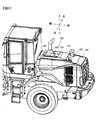
図1は、本発明の一実施の形態に係る作業機械の一例であるホイールローダの側面図である。図1に示すように、ホイールローダは、アーム111、バケット112、および、前輪113等を有する前部車体110と、運転室121、建屋122、および、後輪123等を有する後部車体120とで構成される。
FIG. 1 is a side view of a wheel loader that is an example of a work machine according to an embodiment of the present invention. As shown in FIG. 1, the wheel loader includes an
アーム111はアームシリンダ(不図示)の駆動により上下方向に回動(俯仰動)し、バケット112はバケットシリンダ115の駆動により上下方向に回動(クラウドまたはダンプ)する。前部車体110と後部車体120はセンタピン101により互いに回動自在に連結され、ステアリングシリンダ116の伸縮により後部車体120に対し前部車体110が左右に屈折する。
The
建屋122は、エンジン301や排気ガス浄化装置400、熱交換器や各種油圧機器等を収容する収容室の外郭を構成している。建屋122の左右側面の開口部は、開閉可能な左右一対の建屋カバー130によって覆われている。建屋カバー130はガルウイングタイプの開閉カバーであって、建屋122の天板と建屋カバー130との間に回動支点(ヒンジ)が設けられ、地面に対し略水平に展開する構成とされている。ホイールローダ100の左右側面にそれぞれ設けられた建屋カバー130は、左右で略対称の形状である。
The
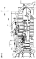
図2は、天板などの上部構造体を取り除いた状態のホイールローダの平面図である。図2に示すように、建屋122の内部に設けられた収容室(収容空間)は、隔壁160によって、車両前側のエンジン室122Eと、車両後側の冷却器室122Cとに仕切られている。
FIG. 2 is a plan view of the wheel loader in a state where an upper structure such as a top plate is removed. As shown in FIG. 2, a storage chamber (storage space) provided inside the
図1に示すように、エンジン室122Eの側面は、建屋カバー130の一部により覆われ、エンジン室122Eの上面は、建屋122の天板を構成するエンジンフード140により覆われている。エンジン室122Eの前面は、前側フレーム810の前面板811(図4参照)により覆われ、エンジン室122Eの後面は、後側フレーム161の隔壁160(図3参照)により覆われている。すなわち、エンジン室122Eは、左右一対の建屋カバー130の一部と、エンジンフード140と、前面板811(図4参照)と、隔壁160(図3参照)によって画成されている。
As shown in FIG. 1, a side surface of the
冷却器室122Cの側面は、建屋カバー130の一部により覆われ、冷却器室122Cの上面は、建屋122の天板を構成する冷却器用建屋カバー132により覆われている。冷却器室122Cの前面は、隔壁160により覆われ、冷却器室122Cの後面は、グリル200により覆われている。すなわち、冷却器室122Cは、左右一対の建屋カバー130の一部と、冷却器用建屋カバー132と、隔壁160と、グリル200によって画成されている。
A side surface of the
冷却器室122Cの内部には、熱交換器ユニット501と、冷却ファンユニット502が配置されている。熱交換器ユニット501は、エンジン301の冷却水を冷却するラジエータ504(図9参照)や、作動油を冷却するオイルクーラ、エンジン301の過給機で加圧された空気を冷却するインタークーラ等の複数の熱交換器と、これらの熱交換器を支持するラジエータフレームを備えている。冷却ファンユニット502は、熱交換器ユニット501を冷却するための冷却風を発生する冷却ファン503(図9参照)と、冷却ファン503(図9参照)を支持するシュラウドを備えている。なお、ホイールローダの機種により、熱交換器ユニット501には、トランスミッションオイルクーラや、運転室121の空調用のエアコンのコンデンサなどの熱交換器も取り付けられる。
A
図1に示すように、冷却器用建屋カバー132の上面からは、エンジン301の駆動に必要な空気をエアクリーナ310(図3参照)を介して外部から取り込むための吸気管145が突出している。図3に示すように、エアクリーナ310は、冷却器室122C内で、隔壁160の直後に設けられている。エアクリーナ310は、吸気配管を介してエンジン301に接続されている。冷却器室122C内にエアクリーナ310を設けることで、エンジン301や排気ガス浄化装置400からエアクリーナ310への熱の影響を抑制できる。これにより、エンジン301で吸入される空気の温度上昇を抑制して、エンジン301での吸気効率の低下を抑制できる。
As shown in FIG. 1, an
図1に示すように、エンジン室122E内におけるエンジン301の上方には、エンジン301の排気ガスを浄化する排気ガス浄化装置400が配設されている。エンジンフード140からは、排気ガスを排出するためのテールパイプ171が突出している。
As shown in FIG. 1, an exhaust
図3は冷却器室122Cの内部を示す斜視図であり、図4はエンジン室122Eの内部を示す斜視図である。図3および図4では、建屋122を構成する建屋カバー130やエンジンフード140、冷却器用建屋カバー132、グリル200等の図示を省略している。
FIG. 3 is a perspective view showing the inside of the
図4に示すように、エンジン室122E内で、エンジン301は後部車体120の不図示のエンジン取り付け用ブラケットに取り付けられている。エンジン301には、過給機(ターボチャージャ)302が取り付けられている。過給機302は、コンプレッサ302aの吸気口が後方を向き、タービン302bの排気口が前方を向くように配設されている。
As shown in FIG. 4, the
図2および図4に示すように、排気ガス浄化装置400はエンジン301の排気流路中に設置された酸化触媒装置(DOC:Diesel Oxidation Catalyst)410と、還元剤噴射装置(DRT:Decomposition Reactor Tube)420と、選択触媒還元装置(SCR:Selective Catalytic Reduction)430と、を備える。排気ガスの流れに沿って、上流側から酸化触媒装置410、還元剤噴射装置420、選択触媒還元装置430の順に配置されている。各後処理装置(410,420,430)同士は、エルボなどの接続配管により接続されている。
As shown in FIGS. 2 and 4, the exhaust gas purifying
酸化触媒装置410は、排気ガスに含まれる一酸化窒素(NO)、一酸化炭素(CO)、炭化水素(HC)等を酸化して除去する酸化触媒と、酸化触媒を保持する円筒状のDOC筐体411とを備えている。酸化触媒装置410の下流側には、還元剤噴射装置420が設置されている。
The
還元剤噴射装置420は、選択触媒還元装置430へ供給される排気ガス中に還元剤である尿素水溶液(以下、尿素水と記す)を噴射する噴射弁429と、噴射弁429を保持する円筒状のDRT筐体421を備えている。噴射弁429は、DRT筐体421の略中央部に設けられている。噴射弁429は、図示しない制御装置からの制御信号に応じて、DRT筐体421内に尿素水を噴射する。噴射弁429は、コイルに電流を流すことにより可動子とコアとを含む磁気回路に磁束を発生させ、可動子をコア側に引き付ける磁気吸引力を作用させることにより、弁体の開閉を行うものであり、周知の電磁駆動式の燃料噴射弁(インジェクタ)と同様の構成を有している。還元剤噴射装置420の下流側には選択触媒還元装置430が設置されている。
The reducing
選択触媒還元装置430は、還元剤として尿素水を利用して排気ガスに含まれる窒素酸化物(NOx)を還元浄化処理する還元触媒と、還元触媒を保持する円筒状のSCR筐体431とを備えている。選択触媒還元装置430には、還元触媒の下流側に酸化触媒が設けられている。
The selective
図3に示すように、噴射弁429は、配管(吸込み配管425a、還元剤供給配管425s)を介して尿素水タンク127に接続されている。尿素水タンク127は、還元剤としての尿素水を蓄える容器である。エンジン室122E内の噴射弁429と、冷却器室122C内の尿素水タンク127との間には尿素水ポンプ128が設けられている。尿素水ポンプ128は、冷却器室122Cの内部において、隔壁160に固定されている。尿素水ポンプ128は、尿素水タンク127内の尿素水を吸い上げて、噴射弁429に尿素水を送給する電動ポンプである。
As shown in FIG. 3, the
図4に示す噴射弁429は、尿素水タンク127から尿素水ポンプ128により供給される尿素水を排気流路中に噴射する。尿素水が噴射されると、選択触媒還元装置430の還元触媒により尿素水からアンモニアが生成され、アンモニアにより排気ガス中のNOxが還元反応して、水と窒素に分解される。選択触媒還元装置430における還元触媒の下流側に設けられた酸化触媒により、排気ガス中のアンモニアが低減される。
The
図3および図4に示すように、後部車体120を構成するリアフレーム220は、左右一対の縦板221と、左右一対の縦板221を前端部および後端部のそれぞれで連結する横板222(前端部の横板については不図示)とで矩形枠状に構成されている。
As shown in FIGS. 3 and 4, the
図4に示すように、排気ガス浄化装置400は、支持構造体であるベースブラケット820を介して、前側フレーム810と後側フレーム161によって支持されている。後側フレーム161は、リアフレーム220を構成する左右一対の縦板221の内側に溶接されるブラケット221bを介して、縦板221に固定されている。後側フレーム161は、門型形状の支持部材であって、左右一対の脚部162が左右一対の縦板221のそれぞれに取り付けられている。左右一対の脚部162には、左右水平方向に延在する支持梁163が固着されている。支持梁163には、前方に突出する突出受部163aが設けられている。なお、図3に示すように、後側フレーム161の後面には、上述した平板状の隔壁160がボルト、ナットなどの締結部材により取り付けられている。
As shown in FIG. 4, the exhaust
図4に示すように、前側フレーム810は、後側フレーム161と同様の構成とされている。前側フレーム810は、リアフレーム220を構成する左右一対の縦板221に固定されている。前側フレーム810は、門型形状の支持部材であって、左右一対の脚部812が左右一対の縦板221のそれぞれに取り付けられている。左右一対の脚部812には、左右水平方向に延在する支持梁813が固着されている。支持梁813には、後方に突出する突出受部813aが設けられている。なお、前側フレーム810の前面には、平板状の前面板811がボルト、ナットなどの締結部材により取り付けられている。
As shown in FIG. 4, the
前側フレーム810の突出受部813aにはベースブラケット820の前脚838が載置され、後側フレーム161の突出受部163aにはベースブラケット820の後脚839が載置される。前脚838がボルトおよびナットにより突出受部813aに固定され、後脚839がボルトおよびナットにより突出受部163aに固定されると、ベースブラケット820が前側フレーム810および後側フレーム161に固定、支持される。
A
このように、排気ガス浄化装置400はベースブラケット820に固定され、ベースブラケット820が前側フレーム810および後側フレーム161に固定されることで、排気ガス浄化装置400がエンジン301の上方において、所定の位置に配置、固定されている。
Thus, the exhaust
図5は、エンジン室122Eを左側方から見た図である。図5において、建屋カバー130の図示は省略している。図5に示すように、エンジン301および排気ガス浄化装置400の上方には、エンジン室122Eを覆うエンジンフード140が設けられている。エンジンフード140の前端部は前側フレーム810の上端部に取り付けられ、エンジンフード140の後端部は後側フレーム161の上端部に取り付けられる。つまり、前側フレーム810および後側フレーム161は、エンジン室122Eを上方で覆うエンジンフード140を支持する支持構造体である。
FIG. 5 is a view of the
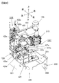
図6は建屋122を左斜め上方から見た斜視図である。図6に示すように、エンジンフード140の平板状の天井板141には、排気ダクト149が設けられている。図7(a)は排気ダクト149の側面模式図、図7(b)は排気ダクト149の平面模式図である。図7(b)において、開口カバー142の図示は省略している。図8は、分解状態の排気ダクト149を示す側面模式図である。排気ダクト149は、エンジン室122Eの内部の空気をエンジン室122Eの外部に排出する排気流路を形成する排気流路形成体であり、天井板141から上方に突出している。
FIG. 6 is a perspective view of the
図7および図8に示すように、排気ダクト149は、天井板141の開口部144に取り付けられたカバー支持枠146、および開口カバー142を有している。開口カバー142は、平板状部材を加工して、下側が開口された四角錐台形状としたものである。
As shown in FIGS. 7 and 8, the
図7(b)に示すように、エンジンフード140を構成する天井板141には、前後方向に沿う一対の長辺と、左右方向に沿う一対の短辺と、を有する矩形状の開口部144が設けられている。開口部144は、還元剤噴射装置420の直上に設けられている。開口部144の周囲には、開口部144よりも一回り大きい矩形枠状のカバー支持枠146が設けられている。
As shown in FIG. 7B, the
図7および図8に示すように、カバー支持枠146は、開口カバー142を支持する支持構造体であって、前後方向に延びる左右一対の縦フレーム147と、左右方向に延びる前後一対の横フレーム148とを備えている。縦フレーム147および横フレーム148は、断面がL字状のアングル(山形鋼)や平板を曲げ加工した鋼材等により形成されている。縦フレーム147および横フレーム148は、開口部144の周縁部に固定される基部147b,148bと、基部147b,148bから立ち上がる複数の支持部147s,148sとを有している。複数の支持部147s,148sの先端には、取付片147a,148aが設けられている。
As shown in FIGS. 7 and 8, the
開口カバー142は、ボルト、ナットにより支持部147s,148sの取付片147a,148aに固定される。開口カバー142は、開口部144よりも面積が大きく、開口部144の全体を上方から覆っている。図7(a)に示すように、開口カバー142の外縁下端部と、天井板141の上面との間には、隙間Dが形成されている。
The
図5において、矢印Fで模式的に示すように、エンジン室122E内の空気は、エンジン301や排気ガス浄化装置400などの発熱体により暖められて上昇し、排気ダクト149内に導入される。排気ダクト149に導入された空気は、矩形状のカバー支持枠146の内側を通過して上昇し、開口カバー142に沿って前後左右側方に流れる。空気は、カバー支持枠146における支持部間の隙間を通り、カバー支持枠146と天井板141との間の隙間Dから外部に排出される。
In FIG. 5, as schematically indicated by an arrow F, the air in the
図9を参照して、排気ガス浄化装置400の尿素水供給システムおよび冷却水循環システムについて説明する。図9は、排気ガス浄化装置400の尿素水供給システムおよび冷却水循環システムについて説明する図である。尿素水供給システムは、尿素水ポンプ128と、尿素水タンク127と配管類で構成されている。尿素水ポンプ128と尿素水タンク127とは、吸込み配管425aおよび戻り配管425bによって接続されている。尿素水ポンプ128と噴射弁429とは還元剤供給配管425sによって接続されている。吸込み配管425aは、尿素水タンク127の底部近傍に尿素水の吸入口426aが配置され、戻り配管425bは、尿素水タンク127の上部近傍に尿素水の排出口426bが配置されている。尿素水ポンプ128によって、尿素水タンク127の底部から吸い上げられた尿素水は、還元剤供給配管425s内に供給され、加圧される。還元剤供給配管425s内の尿素水は、噴射弁429が開くことにより、エンジン301の排気流路に噴射供給される。尿素水の余剰分は、戻り配管425bを介して尿素水タンク127に戻される。
With reference to FIG. 9, the urea water supply system and the cooling water circulation system of the exhaust
排気ガス浄化装置400は、尿素水の温度上昇による尿素水の品質の劣化を防止するために、冷却水循環システムを備えている。冷却水循環システムは、図示しない冷却水ポンプと、配管や弁類で構成され、冷却水(エンジン冷却水)を尿素水タンク127や噴射弁429に導き、冷却水と尿素水とを熱交換させるシステムである。冷却水循環システムは、エンジン冷却系880と、冷却水をエンジン冷却系880から尿素水タンク127や噴射弁429に導く冷媒配管881とを備えている。
The exhaust
エンジン冷却系880は、ラジエータ504により冷却された冷却水をエンジン301に供給することで、エンジン301を冷却する。エンジン301には、エンジン冷却水を循環させるための冷却水ポンプ(不図示)と、サーモスタット305とが設けられている。サーモスタット305は、エンジン冷却水の温度に応じてエンジン冷却系880の経路を全閉から全開の間で開閉する。
The
なお、図示しないが、エンジン内にはサーモスタット305が全閉しているときには、ラジエータ504にエンジン冷却水が供給されないようにエンジン冷却水をバイパスさせるバイパス経路が設けられている。エンジン始動時にエンジン冷却水の温度が低いと、エンジン冷却水がエンジン内で循環し、エンジン301の発熱により暖められる。
Although not shown, a bypass path is provided in the engine to bypass the engine cooling water so that the engine cooling water is not supplied to the
エンジン冷却水が流れる冷媒配管881は、噴射弁429を通過するように配設された第1冷媒配管435と、尿素水タンク127を通過するように配設された第2冷媒配管437とを有している。第1冷媒配管435は、冷却水を噴射弁429に導く第1供給配管435sと、噴射弁429からエンジン301へエンジン冷却水を戻す第1戻り配管435rとを有する。第2冷媒配管437は、冷却水を尿素水タンク127に導く第2供給配管437sと、尿素水タンク127からエンジン301へ冷却水を戻す第2戻り配管437rとを有する。第2冷媒配管437には、図示しない制御装置からの制御信号に応じて、全閉と全開との間で切り換えられる切換弁437vが設けられている。
The
図3を参照して、尿素水タンク周りの配管について説明する。図3に示すように、吸込み配管425aおよび戻り配管425bは、それぞれ尿素水タンク127の上面から尿素水タンク127内に挿入されている。吸込み配管425aおよび戻り配管425bは、隔壁160に取り付けられている尿素水ポンプ128に接続されている。尿素水ポンプ128から吐出された尿素水が流れる還元剤供給配管425sは、隔壁160の開口を介してエンジン室122Eに導かれ、噴射弁429に接続されている(図5参照)。
The piping around the urea water tank will be described with reference to FIG. As shown in FIG. 3, the
第2冷媒配管437を構成する第2供給配管437sは、エンジン室122Eから隔壁160の開口を介して冷却器室122Cに導かれ、尿素水タンク127の上面から尿素水タンク127内に挿入されている。第2冷媒配管437を構成する第2戻り配管437rは、尿素水タンク127の上面から尿素水タンク127の外側に導かれ、さらに隔壁160の開口を介してエンジン室122Eに導かれ、エンジン301に接続されている。つまり、エンジン冷却水が流れる第2冷媒配管437は、尿素水タンク127を通過するように配設されている。
The
図5を参照して、還元剤噴射装置周りの配管について説明する。図5に示すように、冷媒配管881は、エンジン301からベースブラケット820に沿って隔壁160まで導かれ、第1冷媒配管435と第2冷媒配管437に分岐される。第2冷媒配管437は、隔壁160の開口を介して冷却器室122Cに導かれる。
With reference to FIG. 5, the piping around the reducing agent injection device will be described. As shown in FIG. 5, the
第1冷媒配管435を構成する第1供給配管435sは、隔壁160に沿って上方に導かれ、さらに排気ダクト149の後部に向かって前斜め上方に向かって導かれる。第1供給配管435sは、排気ダクト149内で湾曲し、排気ダクト149の前部に向かって前斜め下方に向かって導かれる。第1供給配管435sは、排気ダクト149の前部の下方で折り返され、噴射弁429に向かって後斜め下方に向かって導かれ、噴射弁429に接続されている。
The
第1冷媒配管435を構成する第1戻り配管435rは、噴射弁429から前斜め上方に向かって導かれ、噴射弁429の近傍で折り返され、DRT筐体421に沿って後斜め下方に向かって導かれる。第1戻り配管435rは隔壁160の近傍で下方へ湾曲し、エンジン301に接続されている。
The
還元剤供給配管425sは、隔壁160の開口からエンジン室122Eに導かれ、第1供給配管435sと同様のルートで、第1供給配管435sに近接または接触させた状態で配索されている。還元剤供給配管425sと第1供給配管435sを互いに近接または接触させた状態で配索することで、還元剤供給配管425s内の尿素水と冷却水との熱交換により尿素水の温度を適正に保つことができる。
The reducing
還元剤供給配管425sは、第1供給配管435sとともに、排気ダクト149の後部に向かって前斜め上方に向かって導かれる。還元剤供給配管425sは、排気ダクト149内で湾曲し、排気ダクト149の前部に向かって前斜め下方に向かって導かれる。還元剤供給配管425sは、排気ダクト149の前部の下方で折り返され、噴射弁429に向かって後斜め下方に向かって導かれ、噴射弁429に接続されている。
The reducing
ところで、冷却水を循環させる冷却水ポンプ(不図示)は、エンジン301により駆動される。このため、エンジン301が停止すると、冷却水ポンプも停止するので、冷却水の循環が止まる。しかしながら、エンジン停止後もエンジン301からは輻射熱が放射されるため、エンジン停止後であっても噴射弁429を冷却する必要がある。
By the way, a cooling water pump (not shown) for circulating the cooling water is driven by the
本実施の形態では、噴射弁429に接続される第1供給配管435sを、噴射弁429よりも上方に設け、エンジン停止後にも配管内に冷却水が残存(貯留)する構成とされている。
In the present embodiment, the
図10は、第1供給配管435sおよび還元剤供給配管425sの貯留領域RAについて説明する図である。本実施の形態では、配管(第1供給配管435sおよび還元剤供給配管425s)の中心の頂部TPから配管(第1供給配管435sおよび還元剤供給配管425s)と噴射弁429との接続部(CP1,CP2)までをそれぞれ貯留領域RAと定義する。貯留領域RAは、還元剤噴射装置420と排気ダクト149との間に配置される。
FIG. 10 is a diagram illustrating the storage area RA of the
第1供給配管435sの貯留領域RAの上下方向寸法(高さ寸法)H1は、150mm〜200mm程度とされている。同様に、還元剤供給配管425sの貯留領域RAの上下方向寸法(高さ寸法)H2は、150mm〜200mm程度とされている。これにより、ハッチングで示す貯留領域RAにおいて、冷却水および尿素水が貯留される。第1供給配管435sの貯留領域RAを設けることで、エンジン停止後におけるエンジン301の残熱によるシール部材や配管等の損傷を防止できる。
The vertical dimension (height dimension) H1 of the storage area RA of the
図5に示すように、本実施の形態では、排気ダクト149の内側であって、天井板141の上面よりも上方に、第1供給配管435sおよび還元剤供給配管425sの頂部TPを位置させている。図示するように、貯留領域RAの前後方向長さL1は、開口部144の前後方向長さL2よりも短い。第1供給配管435sおよび還元剤供給配管425sは、平面視で第1供給配管435sおよび還元剤供給配管425sの貯留領域RAの全体が開口部144の内側に収まるように配索されている。
As shown in FIG. 5, in the present embodiment, the tops TP of the
各配管は可撓性を有するホースによって構成され、各配管の配索用のブラケットや取付金具は、エンジンフード140、後側フレーム161や隔壁160などの構成部材に設けられ、各配管が配索用のブラケットや取付金具によって、所定の位置に支持されている。
Each pipe is composed of a flexible hose, and the brackets and mounting brackets for each pipe are provided on components such as the
上述したように、エンジン室122Eの内部で暖められた空気は、上昇して排気ダクト149を介してエンジン室122Eの外部へ排出される。この際、自然対流による空気の流れF(図5で示す模式的な矢印参照)の経路上(流路上)に第1供給配管435sおよび還元剤供給配管425sの貯留領域RAや頂部TPが配置されているので、エンジン停止後に貯留領域RAに貯留される冷却水および尿素水を効果的に冷却できる。
As described above, the air warmed inside the
上述した実施の形態によれば、次の作用効果が得られる。
(1)ホイールローダは、エンジン301の排気ガスを処理する選択触媒還元装置430、および選択触媒還元装置430へ供給される排気ガス中に尿素水を噴射する還元剤噴射装置420を有する排気ガス浄化装置400を備えている。ホイールローダは、エンジン301および排気ガス浄化装置400を収容するエンジン室122Eを画成する建屋122を備えている。建屋122は、エンジン301の上方でエンジン室122Eを覆う天板を構成するエンジンフード140と、エンジンフード140に設けられ、エンジン室122E内の空気をエンジン室122Eの外部に排出する排気ダクト149と、を有している。還元剤噴射装置420には、尿素水を導く還元剤供給配管425sが接続されている。還元剤噴射装置420から上方に延びる還元剤供給配管425sの一部(頂部TP)は、還元剤噴射装置420の上方位置における排気ダクト149内に配置されている。
According to the embodiment described above, the following operational effects can be obtained.
(1) The wheel loader has an exhaust gas purification having a selective
本実施の形態では、排気ダクト149は、エンジンフード140の天井板141の開口部144の上方を覆い、天井板141の上面と隙間を介して配置される開口カバー142と、開口カバー142を支持するカバー支持枠146とを備えている。還元剤供給配管425sの頂部TPが、天井板141の上面よりも上方に位置している。
In the present embodiment, the
これにより、エンジン室122E内で暖められて上昇し、排気ダクト149から排出される空気の流れによって、還元剤供給配管425sを冷却することができる。還元剤供給配管425sの内部の尿素水の温度上昇を抑制できるので、尿素水の品質の劣化を防止できる。
As a result, the reducing
ところで、排気ガス浄化装置400は、エンジン301が停止するのに合わせて尿素水の供給を停止するが、還元剤噴射装置420や尿素水を供給する還元剤供給配管内に還元剤が残ったままであると、周囲の残熱によって水分が蒸発し、尿素が析出することに起因して、還元剤供給配管425sや還元剤噴射装置420に目詰まりが発生するおそれがある。本実施の形態では、還元剤供給配管425s内に残留する尿素水の温度上昇を抑制することができるので、還元剤噴射装置420の目詰まりを防止できる。
By the way, the exhaust
(2)エンジン301の冷却水を還元剤噴射装置420に導く第1供給配管435sの一部が、還元剤噴射装置420の上方位置における排気ダクト149内に配置されている。還元剤供給配管425sと同様に冷却水の供給配管(第1供給配管435s)を配策することで、エンジン301の停止後に第1供給配管435s内に貯留された冷却水の温度上昇を抑制することができるので、冷却水により還元剤噴射装置420を効果的に冷却することができる。この結果、還元剤噴射装置420の接続部におけるシール材や配管(ホース)が損傷することを防止できる。
(2) A part of the
(3)排気ダクト149は、還元剤噴射装置420の直上に位置している。還元剤噴射装置420と排気ダクト149との間には、還元剤供給配管425sおよび第1供給配管435sのそれぞれにおける還元剤噴射装置420との接続部から頂部TPまでの貯留領域RAが配置されている。これにより、貯留領域RAの全体を自然対流による空気の流れによって効果的に冷却することができる。
(3) The
次のような変形も本発明の範囲内であり、変形例の一つ、もしくは複数を上述の実施形態と組み合わせることも可能である。
(変形例1)
上述した実施の形態では、ホースのみによって第1供給配管435sを構成する例について説明したが、本発明はこれに限定されない。図10の二点鎖線で示すように、ホースに貯留部900を介装して、第1供給配管435sをホースと貯留部900を含んで構成してもよい。貯留部900は、ホースの流路断面積よりも大きい流路断面積を有し、冷却水の容積を拡大するために設けられている。貯留部900を排気ダクト149に配置することで、貯留部900内の冷却水を効果的に冷却できる。
The following modifications are also within the scope of the present invention, and one or a plurality of modifications can be combined with the above-described embodiment.
(Modification 1)
In the above-described embodiment, the example in which the
(変形例2)
上述した実施の形態では、冷却水循環システムが尿素水の温度上昇を抑制するために設けられていることについて説明したが、凍結した尿素水を解凍するのに利用してもよい。冬季や寒冷地でクレーン作業を行う際、尿素水が凍結していると、還元剤噴射装置420に尿素水を供給できない。このため、還元剤噴射装置420を使用するには、凍結した尿素水を解凍し、さらに解凍した尿素水が再び凍結することを防止する必要がある。そこで、エンジン301と熱交換することで暖められた冷却水を噴射弁429や尿素水タンク127に導くことで、噴射弁429や尿素水タンク127内における凍結した尿素水を解凍し、解凍された尿素水が再び凍結することを防止することができる。
(Modification 2)
In the above-described embodiment, it has been described that the cooling water circulation system is provided to suppress the temperature rise of the urea water. However, the cooling water circulation system may be used to thaw the frozen urea water. When the crane operation is performed in winter or in a cold region, the urea water cannot be supplied to the reducing
(変形例3)
上述した実施の形態では、還元剤として尿素水溶液を用いた例について説明したが、本発明はこれに限定されない。アンモニア水溶液など種々の還元剤を利用した排気ガス浄化装置400を備える作業機械に本発明を適用することができる。
(Modification 3)
In the above-described embodiment, the example in which the urea aqueous solution is used as the reducing agent has been described, but the present invention is not limited to this. The present invention can be applied to a work machine provided with an exhaust
(変形例4)
上述した実施の形態では、ホイールローダに本発明を適用した例について説明したが、本発明はこれに限定されることなく、油圧ショベルやクレーンなど、種々の作業機械に適用することができる。
(Modification 4)
In the above-described embodiment, the example in which the present invention is applied to the wheel loader has been described. However, the present invention is not limited to this, and can be applied to various work machines such as a hydraulic excavator and a crane.
上記では、種々の実施の形態および変形例を説明したが、本発明はこれらの内容に限定されるものではない。本発明の技術的思想の範囲内で考えられるその他の態様も本発明の範囲内に含まれる。 Although various embodiments and modifications have been described above, the present invention is not limited to these contents. Other embodiments conceivable within the scope of the technical idea of the present invention are also included in the scope of the present invention.
122 建屋、122E エンジン室、140 エンジンフード(天板)、141 天井板(天板)、142 開口カバー、144 開口部、146 カバー支持枠(支持部材)、149 排気ダクト、301 エンジン、400 排気ガス浄化装置、420 還元剤噴射装置、425s 還元剤供給配管、430 選択触媒還元装置、435s 第1供給配管(冷却水供給配管)、900 貯留部 122 building, 122E engine room, 140 engine hood (top plate), 141 ceiling plate (top plate), 142 opening cover, 144 opening, 146 cover support frame (supporting member), 149 exhaust duct, 301 engine, 400 exhaust gas Purifying device, 420 Reducing agent injection device, 425s Reducing agent supply piping, 430 Selective catalyst reducing device, 435s First supply piping (cooling water supply piping), 900 Reservoir
Claims (5)
前記エンジンおよび前記排気ガス浄化装置を収容するエンジン室を画成する建屋を備え、
前記建屋は、前記エンジンの上方で前記エンジン室を覆う天板と、前記天板に設けられ、前記エンジン室内の空気を前記エンジン室の外部に排出する排気ダクトと、を有し、
前記還元剤噴射装置に還元剤を導く還元剤供給配管の一部が、前記還元剤噴射装置の上方位置における前記排気ダクト内に配置されていることを特徴とする作業機械。 In a working machine provided with an exhaust gas purification device having a selective catalyst reduction device that processes exhaust gas of an engine and a reducing agent injection device that injects a reducing agent into exhaust gas supplied to the selective catalyst reduction device,
A building that defines an engine room that houses the engine and the exhaust gas purifying device;
The building includes a top plate that covers the engine chamber above the engine, and an exhaust duct that is provided on the top plate and exhausts air in the engine chamber to the outside of the engine chamber,
A working machine characterized in that a part of a reducing agent supply pipe for introducing a reducing agent to the reducing agent injection device is disposed in the exhaust duct at a position above the reducing agent injection device.
前記エンジンの冷却水を前記還元剤噴射装置に導く冷却水供給配管の一部が、前記還元剤噴射装置の上方位置における前記排気ダクト内に配置されていることを特徴とする作業機械。 The work machine according to claim 1,
A work machine, wherein a part of a cooling water supply pipe for guiding cooling water of the engine to the reducing agent injection device is disposed in the exhaust duct at a position above the reducing agent injection device.
前記還元剤噴射装置の直上に、前記排気ダクトが位置し、
前記還元剤噴射装置と前記排気ダクトの間に、前記還元剤供給配管および前記冷却水供給配管のそれぞれにおける前記還元剤噴射装置との接続部から頂部までの領域が配置されていることを特徴とする作業機械。 The work machine according to claim 2,
The exhaust duct is located directly above the reducing agent injection device,
Between the reducing agent injection device and the exhaust duct, a region from the connection portion to the top of the reducing agent injection device in each of the reducing agent supply pipe and the cooling water supply pipe is arranged. Working machine.
前記排気ダクトは、前記天板の開口部の上方を覆い、前記天板の上面と隙間を介して配置される開口カバーと、前記開口カバーを支持する支持部材とを備え、
前記還元剤供給配管の一部が、前記天板の上面よりも上方に位置していることを特徴とする作業機械。 The work machine according to claim 1,
The exhaust duct includes an opening cover that covers an upper portion of the opening of the top plate and is disposed via a top surface of the top plate and a gap, and a support member that supports the opening cover.
A working machine characterized in that a part of the reducing agent supply pipe is located above the top surface of the top plate.
前記冷却水供給配管は、ホースと、前記ホースに介装され、前記ホースの流路断面積よりも大きい流路断面積を有する貯留部と、を有し、
前記貯留部が、前記排気ダクトに配置されていることを特徴とする作業機械。 The work machine according to claim 2,
The cooling water supply pipe has a hose, and a storage part that is interposed in the hose and has a channel cross-sectional area larger than the channel cross-sectional area of the hose,
A working machine, wherein the storage section is disposed in the exhaust duct.
Priority Applications (6)
| Application Number | Priority Date | Filing Date | Title |
|---|---|---|---|
| JP2016066541A JP6548224B2 (en) | 2016-03-29 | 2016-03-29 | Work machine |
| US15/754,299 US10422264B2 (en) | 2016-03-29 | 2017-01-05 | Work machine |
| PCT/JP2017/000181 WO2017168915A1 (en) | 2016-03-29 | 2017-01-05 | Working machine |
| KR1020187005279A KR102002513B1 (en) | 2016-03-29 | 2017-01-05 | Working machine |
| CN201780002873.8A CN107923285B (en) | 2016-03-29 | 2017-01-05 | Working machine |
| EP17773465.4A EP3438425B1 (en) | 2016-03-29 | 2017-01-05 | Working machine |
Applications Claiming Priority (1)
| Application Number | Priority Date | Filing Date | Title |
|---|---|---|---|
| JP2016066541A JP6548224B2 (en) | 2016-03-29 | 2016-03-29 | Work machine |
Publications (3)
| Publication Number | Publication Date |
|---|---|
| JP2017180214A true JP2017180214A (en) | 2017-10-05 |
| JP2017180214A5 JP2017180214A5 (en) | 2018-08-23 |
| JP6548224B2 JP6548224B2 (en) | 2019-07-24 |
Family
ID=59963974
Family Applications (1)
| Application Number | Title | Priority Date | Filing Date |
|---|---|---|---|
| JP2016066541A Active JP6548224B2 (en) | 2016-03-29 | 2016-03-29 | Work machine |
Country Status (6)
| Country | Link |
|---|---|
| US (1) | US10422264B2 (en) |
| EP (1) | EP3438425B1 (en) |
| JP (1) | JP6548224B2 (en) |
| KR (1) | KR102002513B1 (en) |
| CN (1) | CN107923285B (en) |
| WO (1) | WO2017168915A1 (en) |
Cited By (1)
| Publication number | Priority date | Publication date | Assignee | Title |
|---|---|---|---|---|
| JP2020026763A (en) * | 2018-08-10 | 2020-02-20 | 北越工業株式会社 | Engine drive-type work machine |
Families Citing this family (7)
| Publication number | Priority date | Publication date | Assignee | Title |
|---|---|---|---|---|
| DE102018102845A1 (en) * | 2018-02-08 | 2019-08-08 | Man Truck & Bus Ag | Silencer with integrated tread |
| DE102018213895A1 (en) * | 2018-08-17 | 2020-02-20 | Robert Bosch Gmbh | Arrangement for aftertreatment of the exhaust gas of an internal combustion engine and method for operating one |
| JP7100605B2 (en) * | 2019-04-25 | 2022-07-13 | 株式会社クボタ | Rectifying plate mounting structure and work vehicle |
| US11800692B2 (en) | 2020-03-19 | 2023-10-24 | Nooter/Eriksen, Inc. | System and method for data center cooling with carbon dioxide |
| CN112282917A (en) * | 2020-09-25 | 2021-01-29 | 潍柴动力股份有限公司 | Engine thermal management system and vehicle |
| US11668219B2 (en) | 2020-09-28 | 2023-06-06 | Nooter/Eriksen, Inc. | System and method for treating process exhaust gas |
| US20230116011A1 (en) * | 2021-10-12 | 2023-04-13 | Caterpillar Inc. | Secondary control system and method for mounting with service orientation |
Citations (6)
| Publication number | Priority date | Publication date | Assignee | Title |
|---|---|---|---|---|
| JP2010285814A (en) * | 2009-06-12 | 2010-12-24 | Kobelco Contstruction Machinery Ltd | Working machine |
| JP2014084832A (en) * | 2012-10-25 | 2014-05-12 | Komatsu Ltd | Cooling structure of urea aqueous solution pipeline |
| JP2014181718A (en) * | 2014-05-13 | 2014-09-29 | Komatsu Ltd | Exhaust gas aftertreatment unit and construction vehicle equipped with the same |
| US20140360161A1 (en) * | 2013-06-05 | 2014-12-11 | Caterpillar Global Mining Expanded Products Pty Ltd | Forced air circulation for an aftertreatment module |
| JP2015197079A (en) * | 2014-04-02 | 2015-11-09 | ニッタ株式会社 | Heat-up and heat shielding pipe |
| JP2015229996A (en) * | 2014-06-06 | 2015-12-21 | 日立建機株式会社 | Construction machine |
Family Cites Families (5)
| Publication number | Priority date | Publication date | Assignee | Title |
|---|---|---|---|---|
| JPS563517A (en) | 1979-06-22 | 1981-01-14 | Furukawa Electric Co Ltd | Method of connecting wavy aluminum sheath power cable |
| JP2013241809A (en) * | 2012-05-22 | 2013-12-05 | Caterpillar Sarl | Airframe and work machine |
| JP5591303B2 (en) * | 2012-10-25 | 2014-09-17 | 株式会社小松製作所 | Engine room ventilation structure |
| DE112013000161C5 (en) * | 2013-03-15 | 2023-03-16 | Komatsu Ltd. | Exhaust aftertreatment unit and a construction vehicle containing it |
| US9003779B2 (en) * | 2013-03-26 | 2015-04-14 | Komatsu Ltd. | Wheel loader |
-
2016
- 2016-03-29 JP JP2016066541A patent/JP6548224B2/en active Active
-
2017
- 2017-01-05 KR KR1020187005279A patent/KR102002513B1/en active IP Right Grant
- 2017-01-05 EP EP17773465.4A patent/EP3438425B1/en active Active
- 2017-01-05 WO PCT/JP2017/000181 patent/WO2017168915A1/en active Application Filing
- 2017-01-05 CN CN201780002873.8A patent/CN107923285B/en active Active
- 2017-01-05 US US15/754,299 patent/US10422264B2/en active Active
Patent Citations (6)
| Publication number | Priority date | Publication date | Assignee | Title |
|---|---|---|---|---|
| JP2010285814A (en) * | 2009-06-12 | 2010-12-24 | Kobelco Contstruction Machinery Ltd | Working machine |
| JP2014084832A (en) * | 2012-10-25 | 2014-05-12 | Komatsu Ltd | Cooling structure of urea aqueous solution pipeline |
| US20140360161A1 (en) * | 2013-06-05 | 2014-12-11 | Caterpillar Global Mining Expanded Products Pty Ltd | Forced air circulation for an aftertreatment module |
| JP2015197079A (en) * | 2014-04-02 | 2015-11-09 | ニッタ株式会社 | Heat-up and heat shielding pipe |
| JP2014181718A (en) * | 2014-05-13 | 2014-09-29 | Komatsu Ltd | Exhaust gas aftertreatment unit and construction vehicle equipped with the same |
| JP2015229996A (en) * | 2014-06-06 | 2015-12-21 | 日立建機株式会社 | Construction machine |
Cited By (2)
| Publication number | Priority date | Publication date | Assignee | Title |
|---|---|---|---|---|
| JP2020026763A (en) * | 2018-08-10 | 2020-02-20 | 北越工業株式会社 | Engine drive-type work machine |
| JP7089981B2 (en) | 2018-08-10 | 2022-06-23 | 北越工業株式会社 | Engine-driven work machine |
Also Published As
| Publication number | Publication date |
|---|---|
| CN107923285B (en) | 2020-01-21 |
| WO2017168915A1 (en) | 2017-10-05 |
| EP3438425A1 (en) | 2019-02-06 |
| JP6548224B2 (en) | 2019-07-24 |
| EP3438425B1 (en) | 2020-11-11 |
| CN107923285A (en) | 2018-04-17 |
| EP3438425A4 (en) | 2019-11-06 |
| KR20180031754A (en) | 2018-03-28 |
| US10422264B2 (en) | 2019-09-24 |
| KR102002513B1 (en) | 2019-07-22 |
| US20180238220A1 (en) | 2018-08-23 |
Similar Documents
| Publication | Publication Date | Title |
|---|---|---|
| WO2017168915A1 (en) | Working machine | |
| KR101579213B1 (en) | Exhaust gas aftertreatment unit, and construction vehicle equipped with same | |
| JP5956373B2 (en) | Engine device for work vehicle | |
| JP5799001B2 (en) | Cooling structure for urea aqueous solution piping | |
| US9683348B2 (en) | Engine device | |
| JP5918154B2 (en) | Engine device for work vehicle | |
| US20150204050A1 (en) | Wheel loader | |
| JP6385323B2 (en) | Construction machinery | |
| EP3225749B1 (en) | Work vehicle with an engine and an exhaust gas purifying device | |
| JP5603517B2 (en) | Exhaust gas aftertreatment unit and construction vehicle equipped with the same | |
| JP6284281B2 (en) | Tractor | |
| JP2014190327A (en) | Engine device | |
| US20170211255A1 (en) | Hydraulic excavator | |
| JP6547669B2 (en) | Work machine | |
| JP2016188645A (en) | Work vehicle | |
| JP5481604B1 (en) | Exhaust treatment unit and work vehicle equipped with exhaust treatment unit | |
| KR101578337B1 (en) | Hydraulic shovel | |
| JP2016065542A (en) | Work vehicle |
Legal Events
| Date | Code | Title | Description |
|---|---|---|---|
| A521 | Request for written amendment filed |
Free format text: JAPANESE INTERMEDIATE CODE: A523 Effective date: 20180710 |
|
| A621 | Written request for application examination |
Free format text: JAPANESE INTERMEDIATE CODE: A621 Effective date: 20180710 |
|
| TRDD | Decision of grant or rejection written | ||
| A01 | Written decision to grant a patent or to grant a registration (utility model) |
Free format text: JAPANESE INTERMEDIATE CODE: A01 Effective date: 20190521 |
|
| A711 | Notification of change in applicant |
Free format text: JAPANESE INTERMEDIATE CODE: A712 Effective date: 20190619 |
|
| A61 | First payment of annual fees (during grant procedure) |
Free format text: JAPANESE INTERMEDIATE CODE: A61 Effective date: 20190619 |
|
| R150 | Certificate of patent or registration of utility model |
Ref document number: 6548224 Country of ref document: JP Free format text: JAPANESE INTERMEDIATE CODE: R150 |