JP2017180196A - Control device of multi-cylinder engine - Google Patents
Control device of multi-cylinder engine Download PDFInfo
- Publication number
- JP2017180196A JP2017180196A JP2016066041A JP2016066041A JP2017180196A JP 2017180196 A JP2017180196 A JP 2017180196A JP 2016066041 A JP2016066041 A JP 2016066041A JP 2016066041 A JP2016066041 A JP 2016066041A JP 2017180196 A JP2017180196 A JP 2017180196A
- Authority
- JP
- Japan
- Prior art keywords
- egr
- throttle valve
- engine
- passage
- control device
- Prior art date
- Legal status (The legal status is an assumption and is not a legal conclusion. Google has not performed a legal analysis and makes no representation as to the accuracy of the status listed.)
- Granted
Links
Images


Classifications
-
- Y—GENERAL TAGGING OF NEW TECHNOLOGICAL DEVELOPMENTS; GENERAL TAGGING OF CROSS-SECTIONAL TECHNOLOGIES SPANNING OVER SEVERAL SECTIONS OF THE IPC; TECHNICAL SUBJECTS COVERED BY FORMER USPC CROSS-REFERENCE ART COLLECTIONS [XRACs] AND DIGESTS
- Y02—TECHNOLOGIES OR APPLICATIONS FOR MITIGATION OR ADAPTATION AGAINST CLIMATE CHANGE
- Y02T—CLIMATE CHANGE MITIGATION TECHNOLOGIES RELATED TO TRANSPORTATION
- Y02T10/00—Road transport of goods or passengers
- Y02T10/10—Internal combustion engine [ICE] based vehicles
- Y02T10/12—Improving ICE efficiencies
Abstract
Description
本発明は、多気筒エンジンの制御装置に関し、特に、EGR通路を通して排気を再循環させる多気筒エンジンの制御装置に関する。 The present invention relates to a control device for a multi-cylinder engine, and more particularly to a control device for a multi-cylinder engine that recirculates exhaust gas through an EGR passage.
従来から、多気筒エンジンから排出された排気ガスを多気筒エンジンの吸気側に環流することにより、排気ガス中に含まれる窒素酸化物(NOx)を減少させ、かつ燃費を向上させることができる、EGR(Exhaust Gas Recirculation)制御技術が知られている。EGR制御のうち、多気筒エンジンから排出されたEGRガスを、エンジンの排気通路と、エンジンへの吸気通路とを連結するEGR通路を介して環流させる、いわゆる外部EGRでは、EGR通路を、多気筒エンジンの上流側のスロットル弁と、多気筒エンジンの各気筒への気筒分配を行うためのインテイクマニホルドとの間に連結する。そして、排気通路からのEGRガスは、EGR通路と、吸気通路との連結分から吸気通路に導入され、インテイクマニホルドに到達するまでに、吸気通路の上流側から流れてきた新気と混合され、その後、インテイクマニホルドを介して各気筒に分配される。 Conventionally, by circulating exhaust gas discharged from a multi-cylinder engine to the intake side of the multi-cylinder engine, nitrogen oxide (NOx) contained in the exhaust gas can be reduced and fuel consumption can be improved. An EGR (Exhaust Gas Recirculation) control technique is known. In the so-called external EGR in which EGR gas discharged from a multi-cylinder engine is circulated through an EGR passage that connects an exhaust passage of the engine and an intake passage to the engine in EGR control, the EGR passage is connected to the multi-cylinder. The engine is connected between a throttle valve on the upstream side of the engine and an intake manifold for distributing cylinders to each cylinder of the multi-cylinder engine. The EGR gas from the exhaust passage is introduced into the intake passage from the connection between the EGR passage and the intake passage, and is mixed with the fresh air flowing from the upstream side of the intake passage until reaching the intake manifold. , And distributed to each cylinder via the intake manifold.
通常、EGRガスを吸気通路に環流する場合、吸気通路に導入するEGRガスの総量を管理することはできるものの、多気筒エンジンにおいて、各気筒にどの程度のEGRガスが供給されているかを監視することは行われていない。そして、多気筒エンジンへの新気供給量や各気筒への燃料供給量は、EGR通路を通過したEGRガスが各気筒に均一に分配されている前提で制御されているため、多気筒エンジンの各気筒に実際に供給されるEGRガスの量は、気筒毎に均一であることが求められる。この場合、環流されるガスのEGR濃度又はEGR量が少ない場合には、各気筒に供給されるEGRガスの量が均一でなくともエンジンの効率が低下することはないが、環流されるEGRガスの濃度が高い場合には、各気筒に供給されるEGRガスの量が不均一であると、気筒毎の燃焼効率にばらつきが出てしまい、要求されるエンジンの出力を確保することができない場合があった。 Normally, when the EGR gas is circulated in the intake passage, the total amount of EGR gas introduced into the intake passage can be managed, but in a multi-cylinder engine, how much EGR gas is supplied to each cylinder is monitored. That is not done. The fresh air supply amount to the multi-cylinder engine and the fuel supply amount to each cylinder are controlled on the premise that the EGR gas that has passed through the EGR passage is uniformly distributed to each cylinder. The amount of EGR gas actually supplied to each cylinder is required to be uniform for each cylinder. In this case, if the EGR concentration or EGR amount of the gas to be recirculated is small, the efficiency of the engine does not decrease even if the amount of EGR gas supplied to each cylinder is not uniform, but the recirculated EGR gas When the amount of EGR gas supplied to each cylinder is uneven, the combustion efficiency varies from cylinder to cylinder, and the required engine output cannot be secured. was there.
このような問題を解決すべく、多気筒エンジンにEGRガスを供給する場合に、気筒毎のEGR量の差を少なくし、各気筒に均一にEGRガスを供給する技術が知られている(例えば、特許文献1)。 In order to solve such a problem, when supplying EGR gas to a multi-cylinder engine, a technique for reducing the difference in EGR amount for each cylinder and supplying EGR gas uniformly to each cylinder is known (for example, Patent Document 1).
特許文献1では、スロットル弁と、エンジンとの間に、EGRの混合室を設け、混合室内に乱流を発生させ、EGRと新気を混合し、各気筒に供給するEGRの量を均一にするようにしている。 In Patent Document 1, an EGR mixing chamber is provided between the throttle valve and the engine, turbulence is generated in the mixing chamber, EGR and fresh air are mixed, and the amount of EGR supplied to each cylinder is made uniform. Like to do.
しかしながら、特許文献1の技術では、エンジンの大型化を招き、好ましくない、という問題があった。即ち、スロットル弁とエンジンとの間のスペースは、非常に限られており、このような極めて限られたスペースにEGR用の混合室を設けることは、設計上困難であり、また、仮に混合室を設けられたとしても、エンジンが大型化してしまう。 However, the technique of Patent Document 1 has a problem that it is not preferable because the engine is enlarged. That is, the space between the throttle valve and the engine is very limited, and it is difficult to design a mixing chamber for EGR in such a very limited space. Even if it is provided, the engine will be enlarged.
そこで本発明は、上述した問題点を解決するためになされたものであり、エンジンの大型化を図ることなく、特にEGR濃度が高い場合において、EGRと新気とを混合し、多気筒エンジンの各気筒に均一にEGRガスを分配できる制御装置を提供することを目的とする。 Therefore, the present invention has been made to solve the above-described problems, and without increasing the size of the engine, particularly when the EGR concentration is high, EGR and fresh air are mixed, and the multi-cylinder engine It is an object of the present invention to provide a control device that can uniformly distribute EGR gas to each cylinder.
上述した課題を解決するために、本発明は、多気筒エンジンの制御装置であって、前記多気筒エンジンの吸気系統に設けられ、下流側への新気の導入量を調整するためのスロットル弁と、前記多気筒エンジンと前記スロットル弁との間に設けられたEGR導入口と、前記スロットル弁の開度を制御する開度制御装置と、を備え、前記開度制御装置は、EGR導入口から排気が吸気系統に環流されており、かつEGR率が所定値以上である場合には、EGR率が所定値より小さい場合に比較して前記スロットル弁の最大開度を閉補正する。 In order to solve the above-described problems, the present invention is a control device for a multi-cylinder engine, and is provided in an intake system of the multi-cylinder engine, and is a throttle valve for adjusting the amount of fresh air introduced downstream. And an EGR introduction port provided between the multi-cylinder engine and the throttle valve, and an opening degree control device for controlling the opening degree of the throttle valve, the opening degree control device comprising an EGR introduction port When the exhaust gas is recirculated to the intake system and the EGR rate is greater than or equal to a predetermined value, the maximum opening of the throttle valve is corrected to be closed compared to when the EGR rate is smaller than the predetermined value.
このように構成された本発明によれば、EGR率が所定値以上であり、吸気中のEGR濃度が高い場合には、スロットル弁の最大開度を閉補正することにより、スロットル弁と多気筒エンジンとの間で、新気の流れに乱れを生じさせることができる。そして、スロットル弁と多気筒エンジンとの間、即ちEGR導入口付近で新気の乱流を発生させることにより、新気と、環流された排気との混合を促進することができる。これにより、多気筒エンジンの各気筒に供給される排気の量をより均一にすることができる。 According to the present invention configured as described above, when the EGR rate is equal to or higher than a predetermined value and the EGR concentration during intake is high, the throttle valve and the multi-cylinder are corrected by closing the maximum opening of the throttle valve. It is possible to cause a disturbance in the flow of fresh air with the engine. Then, by generating a turbulent flow of fresh air between the throttle valve and the multi-cylinder engine, that is, in the vicinity of the EGR inlet, it is possible to promote mixing of fresh air and the recirculated exhaust gas. Thereby, the amount of exhaust gas supplied to each cylinder of the multi-cylinder engine can be made more uniform.
また、本発明において、好ましくは、前記排気系統に設けられたタービン、及び前記吸気系統に設けられ前記タービンと連結されたコンプレッサを備えるターボ過給機と、前記排気系統上において前記コンプレッサを迂回するバイパス通路上に設けられたウェイストゲート弁と、をさらに備え、前記開度制御装置によって前記スロットル弁の開度が閉補正された場合、前記ウェイストゲート弁の開度を小さくする。 In the present invention, preferably, a turbocharger including a turbine provided in the exhaust system, a compressor provided in the intake system and connected to the turbine, and bypassing the compressor on the exhaust system. A waste gate valve provided on the bypass passage, and when the opening degree of the throttle valve is corrected by the opening degree control device, the opening degree of the waste gate valve is reduced.
このように構成された本発明によれば、スロットル弁の開度が閉補正された場合にウェイストゲート弁の開度を小さくし、タービンの回転数を上昇させ、これにより、吸気系統内の過給圧を上昇させることができる。これにより、スロットル弁の開度が閉補正されて多気筒エンジンへの吸気量が不足するのを防止することができる。 According to the present invention configured as described above, when the opening degree of the throttle valve is corrected to be closed, the opening degree of the waste gate valve is reduced, and the rotational speed of the turbine is increased. The supply pressure can be increased. Thereby, it is possible to prevent the opening amount of the throttle valve from being closed and the intake amount to the multi-cylinder engine from becoming insufficient.
この場合において、前記スロットル弁の最大開度を閉補正する量は、EGR率が高くなるにしたがって大きくなることが好ましい。 In this case, it is preferable that the amount by which the maximum opening of the throttle valve is corrected to be closed increases as the EGR rate increases.
これにより、EGR率が高い場合に、EGR導入口付近で生じる乱流をより大きくすることができる。従って、EGR率が高い場合においても、各気筒に供給される排気の量を均一にすることができる。 Thereby, when the EGR rate is high, the turbulent flow generated in the vicinity of the EGR inlet can be further increased. Therefore, even when the EGR rate is high, the amount of exhaust supplied to each cylinder can be made uniform.
以上のように、本発明によれば、エンジンの大型化を図ることなく、特にEGR濃度が高い場合において、EGRと新気とを混合し、多気筒エンジンの各気筒に均一にEGRガスを分配できる。 As described above, according to the present invention, EGR and fresh air are mixed and the EGR gas is uniformly distributed to each cylinder of the multi-cylinder engine without increasing the size of the engine, particularly when the EGR concentration is high. it can.
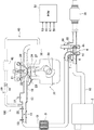
以下、図面を参照して、本発明の実施形態によるエンジンの制御装置について説明する。図1は、エンジンの制御装置が搭載されたエンジンシステムの構成図である。 Hereinafter, an engine control apparatus according to an embodiment of the present invention will be described with reference to the drawings. FIG. 1 is a configuration diagram of an engine system equipped with an engine control device.
図1に示すように、エンジンシステム100は、主に、外部から導入された吸気(空気)が通過する吸気通路10と、この吸気通路10から供給された吸気と、後述する燃料噴射弁23から供給された燃料との混合気を燃焼させて車両の動力を発生するエンジン20(例えばガソリンエンジン)と、このエンジン20内の燃焼により発生した排気ガスを排出する排気通路30とを有する。
As shown in FIG. 1, the
吸気通路10には、上流側から順に、外部から導入された吸気を浄化するエアクリーナー2と、通過する吸気を圧縮して吸気圧力を上昇させる、ターボ過給機4のコンプレッサ4aと、通過する吸気を冷却するインタークーラ9と、通過する吸気量を調整するスロットル弁11と、エンジン20に供給する吸気を一時的に蓄えるサージタンク13と、が設けられている。
In the
スロットル弁11は、エンジン20で要求される新気流量に基づいてその開度が0%〜100%の間で制御される。そして、スロットル弁11の開度が0%の場合、スロットル弁11は、吸気通路10の延びる方向に直交する姿勢に制御され、吸気通路10下流側に向けた新気の流れを遮断する。一方で、スロットル弁11の開度が100%の場合、スロットル弁11は、吸気通路10が延びる方向と平行な姿勢に制御され、新気は、スロットル弁11に邪魔されることなく吸気通路10下流側に向けて滑らかな気流で流れる。
The
また、吸気通路10には、ターボ過給機4のコンプレッサ4aを迂回して吸気を流すエアバイパス通路6が設けられている。具体的には、エアバイパス通路6は、一端がコンプレッサ4aの下流側で且つスロットル弁11の上流側の吸気通路10に接続され、他端がコンプレッサ4aの上流側の吸気通路10に接続されている。また、このエアバイパス通路6上には、エアバイパス通路6を流れる吸気を制御するエアバイパス弁7が設けられている。
The
エンジン20は、主に、吸気通路10から供給された吸気を燃焼室21内に導入する吸気弁22と、燃焼室21に向けて燃料を噴射する燃料噴射弁23と、燃焼室21内に供給された吸気と燃料との混合気に点火する点火プラグ24と、燃焼室21内での混合気の燃焼により往復運動するピストン27と、ピストン27の往復運動により回転されるクランクシャフト28と、燃焼室21内での混合気の燃焼により発生した排気ガスを排気通路30へ排出する排気弁29とを有する。そして、エンジン20は、例えば、4個の燃焼室21及び4個のピストン27を備える、4気筒エンジンである。
The
排気通路30には、上流側から順に、通過する排気ガスによって回転され、この回転によって上記したようにコンプレッサ4aを駆動する、ターボ過給機4のタービン4bと、排気通路30内で生じた異音を処理するためのマフラー38と、が設けられている。また、図示は省略するが、ターボ過給機4と、マフラー38との間には、例えばNOx触媒や三元触媒や酸化触媒などの、排気ガスの浄化機能を有する排気浄化触媒が設けられている。
The
また、排気通路30には、ターボ過給機4のタービン4bを迂回して排気ガスを流すタービンバイパス通路35が設けられている。タービンバイパス通路35は、排気通路30のタービン4b上流側と、タービン4b下流側とを、タービン4bを迂回して連結する通路である。そして、タービンバイパス通路35上には、タービンバイパス通路35を流れる排気ガスを制御するウェイストゲート弁36が設けられている。ウェイストゲート弁36は、後述するPCMによる制御のもと、タービンバイパス通路35を遮断し、又は排気通路30のタービン4b上流側と下流側とを、タービン4bを介さずに連結するように開閉する。
Further, the
さらに、排気通路30と吸気通路10との間には、エンジン20から排出された排気を吸気通路に環流させるための排気環流(EGR)通路40が設けられている。EGR通路40は、エンジン20と、ターボ過給機4のタービン4bとの間で排気通路30から分岐し、スロットル弁11とサージタンク13との間で吸気通路10と合流する。そして、EGR通路40上には、EGR通路40内に流入した排気を冷却するためのEGRクーラー42と、EGRクーラー42よりも吸気通路10側に設けられ、吸気通路10に導入する排気の量を制御するEGR弁44とが設けられている。
Further, an exhaust gas recirculation (EGR)
エンジンシステムは、さらに、システム全体を制御するためのPCM(Power Control Module)51を備えている。そして、PCM51は、例えば、吸気通路10におけるスロットル弁11よりも上流側の吸気通路10内の圧力を検出する第1圧力センサ53、スロットル弁11を通過した新気の流量を検出する流量センサ55、サージタンク13内の圧力を検出する第2圧力センサ57、EGR通路40内のEGR量を検出するEGRセンサ59等からの検出値を受信するように構成されている。
The engine system further includes a PCM (Power Control Module) 51 for controlling the entire system. The
図2は、上述したエンジンシステムの動作を示すフロー図である。 FIG. 2 is a flowchart showing the operation of the engine system described above.
エンジンの運転中において一連の処理が開始すると、エンジンシステム100は、ステップS1において、スロットル弁11の上流側と下流側の圧力を検出する。この処理は、PCM51が、第1圧力センサ53及び第2圧力センサ57の検出値を読み取ることで行われる。
When a series of processes starts during operation of the engine, the
次いで、ステップS2においてエンジンシステム100は、要求スロットル通過流量ga0を算出する。この処理は、PCM51が、例えば、アクセル開度からエンジンのトルク要求を算出し、算出したトルク要求値から、必要とされる新気の量(スロットルを通過する単位時間当たり新気の量)を算出する。そしてPCM51は、第2圧力センサ57の検出値に基づいて、サージタンク13内の圧力を検出し、算出した新気の量を、検出したサージタンク13内の圧力で補正することにより、過渡を考慮したスロットル弁11を通過させるべき新気の量、即ち要求スロットル通過流量ga0を算出する。
Next, in step S2, the
次いで、ステップS3においてエンジンシステム100は、実際にスロットル弁11を通過している新気の量、即ち実スロットル通過流量ga1を算出する。この処理は、PCM51が、現在のスロットル開度及びスロットル弁11の上下の圧力差を検出し、検出した値をベルヌーイの定理に当てはめることで実行される。
Next, in step S3, the
次いで、ステップS4においてエンジンシステム100は、EGR制御を行っているか否かを判断する。そして、例えば、エンジン20の高負荷運転領域においてEGR弁44が開かれており、EGR通路40を介して排気通路20から排気の環流が行われている場合には、ステップS5の処理に進む。
Next, in step S4, the
ステップS5においてエンジンシステム100は、スロットル弁11の開度の上限値TVOlimを設定する。即ち、EGR通路40を介して排気の環流が行われている場合には、スロットル弁11の開度に上限値が設定され、エンジン20からの要求負荷に関わらず、スロットル弁11の最大開度が制限される。上限値TVOlimの値は、実験的に求められた値であり、例えば、図3に示すグラフのように決定されている。
In step S5, the
図3は、EGR率と、上限値TVOlimとの関係を示すグラフであり、縦軸に上限値TVOlim(%)を示し、横軸にEGR率(%)を示す。排気を吸気通路10に環流した際の排気の通路内での分散具合は、EGR通路40の端にあるEGR導入口の位置や形状等によって異なるものである。そして、上限値TVOlimは、EGR導入口の位置や形状等に応じて実験的に求められ、PCM51内に記録されている。例えば、或るエンジン、排気の分散具合が低いエンジンでは、EGR率と上限値TVOlimとの関係は、線L1によって示すものとなる。排気の分散具合が低いエンジンでは、比較的EGR率が低い、E1%のときから上限値TVOlimとして、例えば70%が設定される。そして、上限値TVOlimは、EGR率が高くなるにつれ、低くなる。即ち、排気の分散具合が低いエンジンでは、環流される排気の量が少ないときから、排気環流時にスロットル弁11の下流において乱流を発生させる。従って、排気の分散具合が低いエンジンでは、比較的EGR率が低いとき(E1%)から、上限値TVOlimが設定されている。なお、排気の分散具合が低いエンジンであっても、EGR率がE1%よりも低い場合には、スロットル弁11の下流側において排気の分散具合を考慮する必要がないため、上限値TVOlimは設定されない。
FIG. 3 is a graph showing the relationship between the EGR rate and the upper limit value TVOlim. The vertical axis shows the upper limit value TVOlim (%), and the horizontal axis shows the EGR rate (%). The degree of dispersion in the exhaust passage when the exhaust gas is circulated to the
また、比較的排気の分散具合が高いエンジンでは、EGR率と上限値TVOlimとの関係は、線L2によって示すものとなる。比較的排気の分散具合が高いエンジンでは、EGR率がE1%以上であっても、上限値TVOlimは設定されておらず、EGR率がE1%よりも高いE2%以上となった場合に、上限値TVOlimが設定される。これにより、EGR率がE1%よりも高く、かつE2%以下の場合には、上限値TVOlimが設定されず、スロットル弁11は、エンジンの要求負荷に応じて開度が制御される。そして、EGR率E1%及びE2%も、上限値TVOlimと同様に、実験的に求められ、PCM51に記憶された値である。そして、エンジンシステム100では、エンジンの排気の分散具合に応じて決定されたEGR率(E1又はE2%)を下限値として、EGR率がそれ以上である場合に、上限値TVOlimを設定するようになっている。
In an engine with a relatively high exhaust dispersion, the relationship between the EGR rate and the upper limit value TVOlim is indicated by a line L2. For engines with relatively high exhaust dispersion, even if the EGR rate is E1% or higher, the upper limit TVOlim is not set and the upper limit is set when the EGR rate is E2% or higher, which is higher than E1%. The value TVOlim is set. Thereby, when the EGR rate is higher than E1% and equal to or lower than E2%, the upper limit value TVOlim is not set, and the opening degree of the
一方で、例えば、エンジン20の低負荷運転領域においてEGR弁44が閉じられており、EGR通路40を介して排気の環流が行われていない場合には、ステップS5の処理を行わず、ステップS6以降の処理に進む。
On the other hand, for example, when the
ステップS6においてエンジンシステム100は、要求スロットル通過量ga0と、実スロットル通過量ga1とが等しいか否かを判定する。この処理により、要求スロットル通過量ga0が達成できているか否かを判断することができる。そして、ステップS6において、要求スロットル通過量ga0と、実スロットル通過量ga1とが等しいと判断された場合には、一連の処理を終了し、再度、ステップS1からの処理を繰り返す。
In step S6, the
一方で、ステップS6において、要求スロットル通過量ga0と、実スロットル通過量ga1とが等しくないと判断された場合、エンジンシステム100は、ステップS7において、要求スロットル通過量ga0が、実スロットル通過量ga1よりも大きいか否かを判断する。そして、ステップS7において要求スロットル通過量ga0が、実スロットル通過量ga1よりも大きくないと判断した場合には、現在、エンジンからの要求に対してスロットル弁11を通過する新気の量が多いと判断し、ステップS8においてスロットル弁11の開度を小さくし、一連の処理を終了する。
On the other hand, if it is determined in step S6 that the requested throttle passage amount ga0 is not equal to the actual throttle passage amount ga1, the
また、ステップS7において、要求スロットル通過量ga0が、実スロットル通過量ga1よりも大きいと判断した場合には、ステップS9においてエンジンシステム100は、現在のスロットル弁11の開度が、上限値TVOlimよりも小さいか否かを判断する。なお、EGR通路41を介して排気の環流が行われておらず、ステップS5において上限値TVOlimが設定されていない場合には、常に、現在のスロットル開度が、上限値TVOlimよりも小さいものと判断する。そして、ステップS9の処理は、ステップS7において、実スロットル通過量ga1が、要求スロットル通過量ga0未満であり、エンジン20の要求に対して新気の導入量が少ない場合に行われるものであるから、ステップS9において現在のスロットル弁11の開度が、上限値TVOlimよりも小さいと判断された場合には、ステップS10においてスロットル弁11の開度を大きくし、一連の処理を終了する。
If it is determined in step S7 that the required throttle passage amount ga0 is larger than the actual throttle passage amount ga1, the
一方で、ステップS9において現在のスロットル弁11の開度が、上限値TVOlimよりも小さくないと判断された場合には、ステップS11においてスロットル弁11の開度を、ステップS5で設定された上限値TVOlim以下まで低下させる。これにより、EGR通路41を介して排気が環流されている場合において、EGR率に応じてスロットル弁11の開度を閉補正することができる。そして、スロットル弁11の補正後の開度は、図3に示すグラフに従った開度となる。そして、スロットル弁11の開度を補正することで、スロットル弁11の下流側において乱流が発生し、吸気通路10内の新気と環流された排気との混合を促進し、各気筒に供給される排気の量をより均一にすることができる。
On the other hand, when it is determined in step S9 that the current opening degree of the
このように、本実施形態によれば、EGR率が所定値以上であり(例えば、E1%以上又はE2%以上)、吸気中のEGR濃度が高い場合には、仮に要求されるスロットル弁11の開度が100%であったとしても、スロットル弁11の開度を閉補正することにより、スロットル弁11と多気筒エンジン20との間で、新気の流れに乱れを生じさせることができる。そして、スロットル弁11と多気筒エンジン20との間、即ちEGR導入口付近で新気の乱流を発生させることにより、新気と、環流された排気との混合を促進することができる。これにより、多気筒エンジン20の各気筒に供給される排気の量をより均一にすることができる。
Thus, according to the present embodiment, when the EGR rate is equal to or higher than a predetermined value (for example, E1% or higher or E2% or higher) and the EGR concentration in the intake air is high, the required
また、吸気行程において、スロットル弁11の開度を小さくすると、エンジン20に供給される新気の量が不足し、要求トルクを満足することができない場合も考えられる。このような場合には、スロットル弁11の開度を補正後の開度に維持したまま、エンジン20への過給圧を増加させることにより要求トルクを達成することが好ましい。
In addition, if the opening degree of the
図4は、スロットル弁の開度を閉補正した際の過給圧制御を示すフロー図である。 FIG. 4 is a flowchart showing the supercharging pressure control when the opening degree of the throttle valve is corrected to be closed.
図4に示すように、一連の処理が開始すると、ステップS31においてエンジンシステムは、アクセル開度、エンジン回転数、及び吸気通路10内への新気の流入量を読み込む。この処理は、PCM51が、図示せぬ各種センサの検出値を読み込むことで行われる。
As shown in FIG. 4, when a series of processes starts, the engine system reads the accelerator opening, the engine speed, and the amount of fresh air flowing into the
次いで、ステップS32においてエンジンシステムは、アクセル開度に基づいてトルク要求値を算出し、ステップS33においてトルク要求値を達成するために必要なエンジン20への充填効率CEaを算出する。これらステップS32及びS33によって、アクセル開度に基づくドライバーからの要求に応えるために必要な充填効率CEaを算出する。
Next, in step S32, the engine system calculates a torque request value based on the accelerator opening, and in step S33 calculates a charging efficiency CEa to the
次いで、ステップS34においてエンジンシステムは、エンジン回転数とエンジン負荷に基づいて目標EGR率を決定する。この処理は、読み出されたエンジン回転数とエンジン負荷に基づいて、予めPCM51に記憶されたマップを参照することで行われる。
Next, in step S34, the engine system determines a target EGR rate based on the engine speed and the engine load. This process is performed by referring to a map stored in advance in the
次いで、ステップS35においてエンジンシステムは、決定されたEGR率に基づいて設定される上限値TVOlimに基づき、スロットル弁11の開度を補正した後の充填効率CEbを算出する。具体的には充填効率CEbを算出するためには、制限されるスロットル開度に基づくスロットル通過流量を算出し、スロットル通過流量からインマニ空気量を算出する。そして、充填効率CEbは、算出されたインマニ空気量に基づいて算出される。
Next, in step S35, the engine system calculates the charging efficiency CEb after correcting the opening of the
次いで、ステップS36においてエンジンシステムは、ステップS33で算出した充填効率CEaと、ステップS35で算出した充填効率CEbとを比較し、充填効率CEaが、EGR率を考慮した上記上限値TVOlimに基づくスロットル弁開度補正後の充填効率CEbよりも大きいか否かを判断する。そして、充填効率CEaと充填効率CEbよりも大きくない場合、即ち等しい場合、ステップS37においてエンジンシステムは、継続する計算で使用する充填効率CEとして、充填効率CEaの値をセットする。一方で、充填効率CEbが、充填効率CEaよりも小さい場合、つまり上記上限値TVOlimに基づき実質的にスロットル弁11の開度が制限される場合、ステップS38においてエンジンシステムは、継続する計算で使用する充填効率CEとして、充填効率CEbの値をセットする。
Next, in step S36, the engine system compares the charging efficiency CEa calculated in step S33 with the charging efficiency CEb calculated in step S35, and the charging efficiency CEa is a throttle valve based on the upper limit value TVOlim considering the EGR rate. It is determined whether or not the charging efficiency CEb after the opening correction is larger. If the charging efficiency CEa is not greater than the charging efficiency CEb, that is, if they are equal, in step S37, the engine system sets the value of the charging efficiency CEa as the charging efficiency CE used in the continued calculation. On the other hand, when the charging efficiency CEb is smaller than the charging efficiency CEa, that is, when the opening degree of the
次いで、ステップS39においてエンジンシステムは、設定された充填効率CEに基づき、サージタンク13内の要求圧力Pa(又は要求インマニ圧)を算出する。
Next, in step S39, the engine system calculates a required pressure Pa (or required intake manifold pressure) in the
次いで、ステップS40においてエンジンシステムは、要求スロットル前後差圧を読み出す。この処理は、現在のエンジン回転数と、充填効率から、燃費とスロットルの応答性とを両立するスロットル前後差圧を予め実験的に求めたマップ(図5参照)を、予めPCM51に記憶させておき、当該マップを読み出すことで実行される。
Next, in step S40, the engine system reads the required throttle front-rear differential pressure. In this process, a map (see FIG. 5) in which a differential pressure before and after the throttle that satisfies both the fuel efficiency and the throttle response is experimentally obtained in advance from the current engine speed and charging efficiency is stored in the
次いで、ステップS41においてエンジンシステムは、スロットル弁11の前後差圧の補正量Pbを算出する。前後差圧の補正量Pbとは、スロットル弁11の開度を閉補正したことにより低下した充填効率(CEaとCEbとの差の絶対値)を補うために必要な圧力である。従って、CEaとCEbとの差がない場合には、補正量Pbは0となる。この処理は、具体的には低下する充填効率分を低下する流量に変換し、この流量とスロットル弁開度(通路開口面積)に基づいて前後差圧の補正量Pbを求める。
Next, in step S41, the engine system calculates a correction amount Pb for the differential pressure across the
次いで、ステップS42においてエンジンシステムは、ステップS40において読み出した差圧Pb1と、ステップS41において算出した補正量Pb2とを加算し、スロットル弁11の開度を閉補正したことにより必要となった最終的なスロットル弁11前後の差圧Pbを算出する。そして、ステップS43においてエンジンシステムは、ステップS39において算出されたインマニ圧Paと、ステップS42で算出した補正量Pb2に基づいて、スロットル弁11の開度を閉補正した際のトルク低下を補うために必要なエンジンの目標過給圧Pcを算出する。
Next, in step S42, the engine system adds the differential pressure Pb1 read out in step S40 and the correction amount Pb2 calculated in step S41, and finally becomes necessary by correcting the opening of the
過給圧を制御するための具体的な手段としては、例えば、タービンバイパス通路35に設けられたウェイストゲート弁36の開度を調整する方法がある。即ち、ウェイストゲート弁36の開度を小さくするか、全閉にすると、タービンバイパス通路35が一部縮小もしくは遮断されるため、タービン4b側に向けて流れる排気の量が増加し、タービン4bの出力が増加する。そして、タービン4bの出力が増加すると、コンプレッサ4aによる吸気通路10内の過給圧が上昇する。逆にウェイストゲート弁36の開度を大きくするか、全開にすると、タービンバイパス通路35が拡開されるため、タービン4b側に向けて流れる排気の量が減少し、タービン4bの出力が減少する。そして、タービン4bの出力が減少すると、コンプレッサ4aによる吸気通路10内の過給圧が下降する。
As a specific means for controlling the supercharging pressure, for example, there is a method of adjusting the opening degree of the
以上のような過給圧制御により、スロットル弁11を閉じたことによって、エンジン20への給気量が低下したとしても、スロットル弁11以外の構成によってエンジン20への過給圧を上昇させることができる。これにより、スロットル弁11の開度を補正後の開度に維持したまま、エンジン20への過給圧を増加させることにより要求トルクを達成することができる。
Even if the air supply amount to the
4 ターボ過給機
10 吸気通路
11 スロットル弁11
13 サージタンク
20 多気筒エンジン
40 EGR通路
51 PCM
100 エンジンシステム
13
100 engine system
Claims (3)
前記多気筒エンジンの吸気系統に設けられ、下流側への新気の導入量を調整するためのスロットル弁と、
前記多気筒エンジンと前記スロットル弁との間に設けられたEGR導入口と、
前記スロットル弁の開度を制御する開度制御装置と、を備え、
前記開度制御装置は、EGR導入口から排気が吸気系統に環流されており、かつEGR率が所定値以上である場合には、EGR率が所定値より小さい場合に比較して前記スロットル弁の最大開度を閉補正する、多気筒エンジンの制御装置。 A control device for a multi-cylinder engine,
A throttle valve provided in the intake system of the multi-cylinder engine for adjusting the amount of fresh air introduced downstream;
An EGR inlet provided between the multi-cylinder engine and the throttle valve;
An opening degree control device for controlling the opening degree of the throttle valve,
When the exhaust gas is recirculated from the EGR introduction port to the intake system and the EGR rate is equal to or higher than a predetermined value, the opening degree control device is configured so that the throttle valve A multi-cylinder engine controller that compensates for the maximum opening.
前記排気系統上において前記コンプレッサを迂回するバイパス通路上に設けられたウェイストゲート弁と、をさらに備え、
前記開度制御装置によって前記スロットル弁の開度が閉補正された場合、前記ウェイストゲート弁の開度を小さくする、請求項1に記載の多気筒エンジンの制御装置。 A turbocharger comprising a turbine provided in the exhaust system, and a compressor provided in the intake system and connected to the turbine;
A wastegate valve provided on a bypass passage that bypasses the compressor on the exhaust system,
The multi-cylinder engine control device according to claim 1, wherein when the opening degree of the throttle valve is corrected to be closed by the opening degree control device, the opening degree of the waste gate valve is reduced.
Priority Applications (1)
| Application Number | Priority Date | Filing Date | Title |
|---|---|---|---|
| JP2016066041A JP6410216B2 (en) | 2016-03-29 | 2016-03-29 | Multi-cylinder engine controller |
Applications Claiming Priority (1)
| Application Number | Priority Date | Filing Date | Title |
|---|---|---|---|
| JP2016066041A JP6410216B2 (en) | 2016-03-29 | 2016-03-29 | Multi-cylinder engine controller |
Publications (2)
| Publication Number | Publication Date |
|---|---|
| JP2017180196A true JP2017180196A (en) | 2017-10-05 |
| JP6410216B2 JP6410216B2 (en) | 2018-10-24 |
Family
ID=60005244
Family Applications (1)
| Application Number | Title | Priority Date | Filing Date |
|---|---|---|---|
| JP2016066041A Expired - Fee Related JP6410216B2 (en) | 2016-03-29 | 2016-03-29 | Multi-cylinder engine controller |
Country Status (1)
| Country | Link |
|---|---|
| JP (1) | JP6410216B2 (en) |
Cited By (2)
| Publication number | Priority date | Publication date | Assignee | Title |
|---|---|---|---|---|
| JP2019148184A (en) * | 2018-02-26 | 2019-09-05 | トヨタ自動車株式会社 | Vehicle control device |
| JP2020097916A (en) * | 2018-12-19 | 2020-06-25 | トヨタ自動車株式会社 | Engine device |
Citations (6)
| Publication number | Priority date | Publication date | Assignee | Title |
|---|---|---|---|---|
| JPH11351071A (en) * | 1998-06-12 | 1999-12-21 | Nissan Motor Co Ltd | Egr system for internal-combustion engine |
| JP2006257940A (en) * | 2005-03-16 | 2006-09-28 | Nissan Motor Co Ltd | Engine control device |
| US20090132153A1 (en) * | 2005-12-20 | 2009-05-21 | Borgwarner Inc. | Controlling exhaust gas recirculation in a turbocharged compression-ignition engine system |
| JP2012102617A (en) * | 2010-11-08 | 2012-05-31 | Daihatsu Motor Co Ltd | Internal combustion engine |
| JP2013245572A (en) * | 2012-05-24 | 2013-12-09 | Mitsubishi Automob Eng Co Ltd | Exhaust gas recirculation device |
| JP2015209815A (en) * | 2014-04-25 | 2015-11-24 | トヨタ自動車株式会社 | Internal combustion engine |
-
2016
- 2016-03-29 JP JP2016066041A patent/JP6410216B2/en not_active Expired - Fee Related
Patent Citations (7)
| Publication number | Priority date | Publication date | Assignee | Title |
|---|---|---|---|---|
| JPH11351071A (en) * | 1998-06-12 | 1999-12-21 | Nissan Motor Co Ltd | Egr system for internal-combustion engine |
| JP2006257940A (en) * | 2005-03-16 | 2006-09-28 | Nissan Motor Co Ltd | Engine control device |
| US20090132153A1 (en) * | 2005-12-20 | 2009-05-21 | Borgwarner Inc. | Controlling exhaust gas recirculation in a turbocharged compression-ignition engine system |
| JP2009520918A (en) * | 2005-12-20 | 2009-05-28 | ボーグワーナー・インコーポレーテッド | Exhaust gas recirculation control method in compression ignition engine system with turbocharger |
| JP2012102617A (en) * | 2010-11-08 | 2012-05-31 | Daihatsu Motor Co Ltd | Internal combustion engine |
| JP2013245572A (en) * | 2012-05-24 | 2013-12-09 | Mitsubishi Automob Eng Co Ltd | Exhaust gas recirculation device |
| JP2015209815A (en) * | 2014-04-25 | 2015-11-24 | トヨタ自動車株式会社 | Internal combustion engine |
Cited By (3)
| Publication number | Priority date | Publication date | Assignee | Title |
|---|---|---|---|---|
| JP2019148184A (en) * | 2018-02-26 | 2019-09-05 | トヨタ自動車株式会社 | Vehicle control device |
| JP7087440B2 (en) | 2018-02-26 | 2022-06-21 | トヨタ自動車株式会社 | Vehicle control unit |
| JP2020097916A (en) * | 2018-12-19 | 2020-06-25 | トヨタ自動車株式会社 | Engine device |
Also Published As
| Publication number | Publication date |
|---|---|
| JP6410216B2 (en) | 2018-10-24 |
Similar Documents
| Publication | Publication Date | Title |
|---|---|---|
| US20090077968A1 (en) | Turbocharged Engine Control Operation with Adjustable Compressor Bypass | |
| JP5506567B2 (en) | Internal combustion engine | |
| US10190485B2 (en) | Control apparatus for engine | |
| JP2005233033A (en) | Control device of diesel engine | |
| JP4631598B2 (en) | Supercharging pressure control device | |
| US9267430B2 (en) | Engine controlling emissions during transient operations | |
| JP6394529B2 (en) | Engine control device | |
| WO2015053260A1 (en) | Control device for internal combustion engine | |
| JP2014169644A (en) | Control device for internal combustion engine | |
| JP4442643B2 (en) | Exhaust gas purification control device for internal combustion engine | |
| US10125701B2 (en) | Method for operating an internal combustion engine, in particular a diesel engine | |
| JP2014034959A (en) | Exhaust gas recirculation device of engine with supercharger | |
| JP6056822B2 (en) | Engine exhaust gas recirculation control device | |
| JP6410216B2 (en) | Multi-cylinder engine controller | |
| JP5679185B2 (en) | Control device for internal combustion engine | |
| JP2006299892A (en) | Internal combustion engine with supercharger | |
| US10273890B2 (en) | Internal combustion engine | |
| JP4911432B2 (en) | Control device for internal combustion engine | |
| JP6907977B2 (en) | Turbocharger controller | |
| JP5018810B2 (en) | Control device for internal combustion engine | |
| JP2014159756A (en) | Control device for internal combustion engine | |
| JP2019152122A (en) | Internal combustion engine system | |
| JP7226406B2 (en) | Control device for internal combustion engine | |
| US9885308B2 (en) | Control apparatus of engine | |
| KR101673672B1 (en) | System for piston cooling of vehicle |
Legal Events
| Date | Code | Title | Description |
|---|---|---|---|
| A977 | Report on retrieval |
Free format text: JAPANESE INTERMEDIATE CODE: A971007 Effective date: 20180117 |
|
| A131 | Notification of reasons for refusal |
Free format text: JAPANESE INTERMEDIATE CODE: A131 Effective date: 20180129 |
|
| A521 | Request for written amendment filed |
Free format text: JAPANESE INTERMEDIATE CODE: A523 Effective date: 20180322 |
|
| TRDD | Decision of grant or rejection written | ||
| A01 | Written decision to grant a patent or to grant a registration (utility model) |
Free format text: JAPANESE INTERMEDIATE CODE: A01 Effective date: 20180903 |
|
| A61 | First payment of annual fees (during grant procedure) |
Free format text: JAPANESE INTERMEDIATE CODE: A61 Effective date: 20180916 |
|
| R150 | Certificate of patent or registration of utility model |
Ref document number: 6410216 Country of ref document: JP Free format text: JAPANESE INTERMEDIATE CODE: R150 |
|
| LAPS | Cancellation because of no payment of annual fees |