JP2017176486A - Coupled artificial tooth row - Google Patents
Coupled artificial tooth row Download PDFInfo
- Publication number
- JP2017176486A JP2017176486A JP2016068875A JP2016068875A JP2017176486A JP 2017176486 A JP2017176486 A JP 2017176486A JP 2016068875 A JP2016068875 A JP 2016068875A JP 2016068875 A JP2016068875 A JP 2016068875A JP 2017176486 A JP2017176486 A JP 2017176486A
- Authority
- JP
- Japan
- Prior art keywords
- artificial tooth
- artificial
- tooth row
- teeth
- occlusal surface
- Prior art date
- Legal status (The legal status is an assumption and is not a legal conclusion. Google has not performed a legal analysis and makes no representation as to the accuracy of the status listed.)
- Withdrawn
Links
Images


Landscapes
- Dental Prosthetics (AREA)
Abstract
Description
本発明は、インプラントに用いられる、複数の人工歯が連結されてなる連結人工歯列に関する。 The present invention relates to a connected artificial tooth row formed by connecting a plurality of artificial teeth used in an implant.
義歯を利用する人々にとって、義歯は体の一部として機能し、日常生活を送る上で欠かすことができないものである。また義歯等の上部構造体は毎日口腔内で機能していることから、その消耗も激しく、一定の期間でメンテナンスを行い、新しい上部構造体への取り換えが必要である。 For people who use dentures, dentures function as part of the body and are indispensable for living daily life. In addition, since superstructures such as dentures function daily in the oral cavity, their consumption is severe, and it is necessary to perform maintenance for a certain period of time and to replace them with new superstructures.
特許文献1には、義歯やインプラントの暫間補綴物、最終補綴物の連結歯に関する発明が開示されている。これは、複数の人工歯が連結材料により繋ぎ合わされており、人工歯を義歯床に固定する際に複数の人工歯をまとめて排列することが可能とされている。
人工歯根(インプラント)を顎骨に埋設し、当該人工歯根のうち口腔内側に配置された端部に連結部材として機能するアバットメントを取り付け、ここに人工歯を取り付ける、いわゆるインプラント治療がある。このようなインプラント治療に用いる人工歯についてもより利便性の高いものが求められている。しかしながら、従来技術ではインプラントについてこのような検討がなされてこなかった。 There is a so-called implant treatment in which an artificial tooth root (implant) is embedded in a jawbone, an abutment functioning as a connecting member is attached to an end portion of the artificial tooth root disposed inside the oral cavity, and an artificial tooth is attached thereto. A more convenient artificial tooth used for such implant treatment is also demanded. However, in the prior art, such examination has not been made on implants.
そこで本発明は、上記問題点に鑑み、インプラントに用いられる利便性の高い連結人工歯列を提供することを課題とする。 In view of the above problems, an object of the present invention is to provide a highly convenient connected artificial dentition used for an implant.
以下、本発明について説明する。ここではわかりやすさのため括弧書きにて図面の参照符号を付すが、本発明はこれに限定されるものではない。 The present invention will be described below. Here, for ease of understanding, reference numerals of the drawings are given in parentheses, but the present invention is not limited to this.
本発明の1つの態様は、樹脂製の複数の人工歯(11)が一体に連結されており、1つの面に咬合面(11a)が形成されるとともに、咬合面とは反対側の面には、人工歯根との連結部材が挿入されるべき穴(12)が設けられている、連結人工歯列(10)である。 ここで、「人工歯根との連結部材」は、人工歯根に連結されるアバットメント、シリンダー等を挙げることができる。 In one aspect of the present invention, a plurality of resin-made artificial teeth (11) are integrally connected, an occlusal surface (11a) is formed on one surface, and the surface opposite to the occlusal surface is formed. Is a connection artificial tooth row (10) provided with a hole (12) into which a connection member with the artificial tooth root is to be inserted. Here, examples of the “connecting member with the artificial tooth root” include an abutment and a cylinder connected to the artificial tooth root.
連結人工歯列(10)の穴(12)は全ての人工歯(11)に設けることができる。 The holes (12) of the connected artificial teeth row (10) can be provided in all artificial teeth (11).
上記人工歯(11)は樹脂材料であり、ポリメタクリル酸メチル樹脂により形成されていてもよい。 The artificial tooth (11) is a resin material, and may be formed of a polymethyl methacrylate resin.
本発明によれば、インプラントに取り付ける人工歯を複数まとめて取り扱うことができ、利便性が高い。また、CAD/CAMを使用して樹脂材料で加工するため、義歯やインプラント補綴物で症例を選ばずに使用することが可能である。 According to the present invention, a plurality of artificial teeth to be attached to an implant can be handled together, which is highly convenient. Moreover, since it processes with a resin material using CAD / CAM, it is possible to use it without choosing a case with dentures or an implant prosthesis.
以下本発明を図面に示す形態に基づき説明する。ただし本発明はこれら形態に限定されるものではない。 The present invention will be described below based on embodiments shown in the drawings. However, the present invention is not limited to these forms.
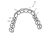
図1は、1つの形態にかかる連結人工歯列10の斜視図、図2は連結人工歯列10を咬合面側からみた平面図、図3は連結人工歯列10を穴12側から見た裏面図をそれぞれ示した。
1 is a perspective view of a connected
図1〜図3よりわかるように、連結人工歯列10は、複数の人工歯11が連結して一体に形成されている。各人工歯11は咬合面11aを有しており、天然歯の咬合面が模擬され、天然歯の咬合面と同様に機能するように凹凸を具備する。一方、咬合面11aとは反対側となる面には、人工歯根(インプラント)との連結部材であるアバットメント、シリンダーに連結する穴12が設けられている。
As can be seen from FIGS. 1 to 3, the connected
穴12は全ての人工歯11に設けられていることが好ましい。これにより人工歯根が配置された位置に対して柔軟に対応することができる。ただし、これに限られることはなく、連結人工歯列10が適切に口腔内に保持できる限りにおいて、少なくとも1つの人工歯11に穴12が設けられていればよい。従って、必要に応じて1又は複数の人工歯11に穴12が形成される。
The
ここで、連結人工歯列10は人工歯11からなり、歯肉を模した部位を有していない。従って、その作製も容易である。
Here, the connected
このような連結人工歯列10によれば、人工歯根に対してまとめて人工歯11を取り付けることができるため利便性を高めることができる。
According to such a connected
連結人工歯列10を構成する樹脂材料としては、特に限定されることはないが、ポリメタクリル酸メチル樹脂(PMMA)等を挙げることができる。PMMAを用いることにより口腔内での安定性を高めることができる。
Although it does not specifically limit as a resin material which comprises the connection artificial tooth row | line |
連結人工歯列10に含まれる人工歯11の数は2つ以上であればよく、その数は限定されない。上記形態のように全歯を含むものであってもよいし、一部であってもよい。
The number of
このような連結人工歯列10は、例えば次のように作製することができる。以下に連結人工歯列10の作製方法の1つの例としてCAD/CAMを用いた例を説明する。
Such a connected
初めに、現状における患者の口腔内の形態を得るため、そのときに使用している義歯の咬合面形態を三次元計測機、又は口腔内計測器で計測し、CADにデータとして形状を取り込む。
得られたデータからCADにて作図を行い、データが不足している部分をCAD上にて補って修整する。
このようにして得られた歯牙形状のデータをCAMを用いて工作機械を制御し、板状のPMMA等の材料から連結人工歯列10を削り出す。
これにより連結人工歯列10を作製することができる。
First, in order to obtain the present form in the oral cavity of the patient, the occlusal surface form of the denture used at that time is measured with a three-dimensional measuring instrument or an intraoral measuring instrument, and the shape is taken into CAD as data.
From the obtained data, drawing is performed by CAD, and the portion lacking data is corrected and corrected on CAD.
The machine tool is controlled by using the CAM data on the tooth shape data thus obtained, and the connected
Thereby, the connection artificial tooth row |
以上のような連結人工歯列10は口腔内に装着されて義歯又はインプラントブリッジとして機能する。すなわち、口腔内の顎骨に埋設された人工歯根(インプラント)のうち口腔内側の端部に、アバットメントやシリンダーが取り付けられる。そして、このアバットメントやシリンダーを連結人工歯列10の穴12に挿入することにより、連結人工歯列10が口腔内に固定される。
The above-mentioned connected
10 連結人工歯列
11 人工歯
11a 咬合面
12 穴
DESCRIPTION OF
Claims (3)
Priority Applications (1)
| Application Number | Priority Date | Filing Date | Title |
|---|---|---|---|
| JP2016068875A JP2017176486A (en) | 2016-03-30 | 2016-03-30 | Coupled artificial tooth row |
Applications Claiming Priority (1)
| Application Number | Priority Date | Filing Date | Title |
|---|---|---|---|
| JP2016068875A JP2017176486A (en) | 2016-03-30 | 2016-03-30 | Coupled artificial tooth row |
Publications (1)
| Publication Number | Publication Date |
|---|---|
| JP2017176486A true JP2017176486A (en) | 2017-10-05 |
Family
ID=60002968
Family Applications (1)
| Application Number | Title | Priority Date | Filing Date |
|---|---|---|---|
| JP2016068875A Withdrawn JP2017176486A (en) | 2016-03-30 | 2016-03-30 | Coupled artificial tooth row |
Country Status (1)
| Country | Link |
|---|---|
| JP (1) | JP2017176486A (en) |
Cited By (2)
| Publication number | Priority date | Publication date | Assignee | Title |
|---|---|---|---|---|
| EP3939539A1 (en) | 2020-07-14 | 2022-01-19 | Kabushiki Kaisha Shofu | Partially connected full denture having an adjustable dental arch and occlusion curvature |
| WO2024077100A1 (en) * | 2022-10-07 | 2024-04-11 | TruBridge Dental L.L.C. | Dental restoration system and method |
-
2016
- 2016-03-30 JP JP2016068875A patent/JP2017176486A/en not_active Withdrawn
Cited By (3)
| Publication number | Priority date | Publication date | Assignee | Title |
|---|---|---|---|---|
| EP3939539A1 (en) | 2020-07-14 | 2022-01-19 | Kabushiki Kaisha Shofu | Partially connected full denture having an adjustable dental arch and occlusion curvature |
| US11583375B2 (en) | 2020-07-14 | 2023-02-21 | Kabushiki Kaisha Shofu | Partial connection full arch artificial tooth having adjustability of dental arch and occlusion curvature |
| WO2024077100A1 (en) * | 2022-10-07 | 2024-04-11 | TruBridge Dental L.L.C. | Dental restoration system and method |
Similar Documents
| Publication | Publication Date | Title |
|---|---|---|
| US20210212804A1 (en) | Overdenture and Dental Implant Framework | |
| US10123856B2 (en) | Dental framework and prosthesis | |
| US10980618B2 (en) | Dental framework and prosthesis | |
| US10426711B2 (en) | Dental implant framework | |
| AU2004200418B2 (en) | Device and Method for Manufacturing Dental Prosthesis | |
| US8403669B2 (en) | Artificial tooth | |
| WO2019003409A1 (en) | Connected artificial teeth | |
| JP2019005599A (en) | Manufacturing method of tooth abutment for dental prosthesis support | |
| KR101539089B1 (en) | Dental prosthesis method using 3d printer | |
| US20200078143A1 (en) | Dental Framework and Prosthesis | |
| MX2010001829A (en) | Method for manufacturing the one body abutment of implant. | |
| CA3017503C (en) | Dental framework and prosthesis | |
| US11364101B2 (en) | Dental implant framework | |
| JP2012024396A (en) | Method for manufacture dental prosthesis, dental prosthesis, and method for acquiring manufacturing data of dental prosthesis | |
| KR20110035480A (en) | A guide block for operating dental implant, assembly of the guide block and method of operating dental implant using the same | |
| Park et al. | Three dimensional finite element analysis of the stress distribution around the mandibular posterior implant during non-working movement according to the amount of cantilever | |
| JP2017176486A (en) | Coupled artificial tooth row | |
| US10105200B2 (en) | Method for producing a dental model and carrying plate for receiving same | |
| US20150327959A1 (en) | Method for positioning artificial posterior teeth | |
| JP2018196535A (en) | Standard denture base, standard denture, partial denture making kit and partial denture making method | |
| CN110099650B (en) | Artificial tooth | |
| JP2014198132A (en) | Scanning instrument | |
| JP2010187884A (en) | Method for manufacturing abutment for dental implant | |
| JP2013202256A (en) | Scanning jig | |
| Seth et al. | Effect of varying inter-implant distance in a two implant-three prosthetic unit dental system: A finite element analysis study |
Legal Events
| Date | Code | Title | Description |
|---|---|---|---|
| A621 | Written request for application examination |
Free format text: JAPANESE INTERMEDIATE CODE: A621 Effective date: 20190313 |
|
| A761 | Written withdrawal of application |
Free format text: JAPANESE INTERMEDIATE CODE: A761 Effective date: 20190808 |