JP2017175744A - Portable backup power supply device - Google Patents
Portable backup power supply device Download PDFInfo
- Publication number
- JP2017175744A JP2017175744A JP2016057909A JP2016057909A JP2017175744A JP 2017175744 A JP2017175744 A JP 2017175744A JP 2016057909 A JP2016057909 A JP 2016057909A JP 2016057909 A JP2016057909 A JP 2016057909A JP 2017175744 A JP2017175744 A JP 2017175744A
- Authority
- JP
- Japan
- Prior art keywords
- battery
- battery units
- unit
- power supply
- supply device
- Prior art date
- Legal status (The legal status is an assumption and is not a legal conclusion. Google has not performed a legal analysis and makes no representation as to the accuracy of the status listed.)
- Granted
Links
- 238000004891 communication Methods 0.000 description 32
- 230000005540 biological transmission Effects 0.000 description 9
- 238000010586 diagram Methods 0.000 description 6
- 238000007599 discharging Methods 0.000 description 5
- 238000012545 processing Methods 0.000 description 4
- 230000003247 decreasing effect Effects 0.000 description 2
- 230000000694 effects Effects 0.000 description 2
- 238000000034 method Methods 0.000 description 2
- 101000741965 Homo sapiens Inactive tyrosine-protein kinase PRAG1 Proteins 0.000 description 1
- 102100038659 Inactive tyrosine-protein kinase PRAG1 Human genes 0.000 description 1
- HBBGRARXTFLTSG-UHFFFAOYSA-N Lithium ion Chemical compound [Li+] HBBGRARXTFLTSG-UHFFFAOYSA-N 0.000 description 1
- 238000006243 chemical reaction Methods 0.000 description 1
- 239000000446 fuel Substances 0.000 description 1
- 230000020169 heat generation Effects 0.000 description 1
- 229910001416 lithium ion Inorganic materials 0.000 description 1
- 238000005259 measurement Methods 0.000 description 1
- 238000012986 modification Methods 0.000 description 1
- 230000004048 modification Effects 0.000 description 1
Images


Classifications
-
- Y—GENERAL TAGGING OF NEW TECHNOLOGICAL DEVELOPMENTS; GENERAL TAGGING OF CROSS-SECTIONAL TECHNOLOGIES SPANNING OVER SEVERAL SECTIONS OF THE IPC; TECHNICAL SUBJECTS COVERED BY FORMER USPC CROSS-REFERENCE ART COLLECTIONS [XRACs] AND DIGESTS
- Y02—TECHNOLOGIES OR APPLICATIONS FOR MITIGATION OR ADAPTATION AGAINST CLIMATE CHANGE
- Y02E—REDUCTION OF GREENHOUSE GAS [GHG] EMISSIONS, RELATED TO ENERGY GENERATION, TRANSMISSION OR DISTRIBUTION
- Y02E60/00—Enabling technologies; Technologies with a potential or indirect contribution to GHG emissions mitigation
- Y02E60/10—Energy storage using batteries
Abstract
Description
本発明は、電池ユニットを分割式とした可搬型バックアップ電源装置に関する。 The present invention relates to a portable backup power supply device in which a battery unit is divided.
可搬型バックアップ電源装置において、その電池ユニットを分割式とすれば、分割した個々のユニットを小寸法かつ軽量とすることができ、その結果、例えば災害時においても人力で容易に運搬することが可能となる。また、予算に応じて少ない数のユニットを初期導入し、後日、追加して容量を増大することが可能となる。 In a portable backup power supply device, if the battery unit is divided, each divided unit can be reduced in size and weight, and as a result, it can be easily transported manually even in the event of a disaster, for example. It becomes. Also, it is possible to initially introduce a small number of units according to the budget, and add them later to increase the capacity.
しかしながら、電池ユニットを分割式とすると、電池残量の互いに異なる電池ユニットや、新旧の入り交じった電池ユニット等の不特定の電池ユニットが相互に接続される可能性がある。電池残量の互いに異なる電池ユニットが互いに並列に接続されると、残量の少ない電池ユニットに大電流が流れて発熱や発火の生じるおそれがある。また、新旧の入り交じった電池ユニットが混在していると、電池ユニットの個体識別が困難となり、無償修理保証や事故解析時に不都合が生じる。さらに、何台の電池ユニットが接続されているのか把握できない場合がある。 However, if the battery unit is divided, unspecified battery units such as battery units having different battery levels or old and new battery units may be connected to each other. When battery units having different battery levels are connected in parallel to each other, a large current may flow through the battery units with a small remaining level, which may cause heat generation or ignition. In addition, when old and new battery units are mixed, it is difficult to identify individual battery units, which causes inconvenience during free repair guarantee and accident analysis. Furthermore, it may not be possible to know how many battery units are connected.
互いに並列接続した複数の電池ユニットのうちの一部の電池ユニットに大電流が流れてしまうことを防止できる蓄電池システムが、特許文献1に開示されている。この蓄電池システムにおいて、複数の蓄電池モジュールは複数のグループに分割され、各グループに属する蓄電池モジュールの電流路は1つに並列結合されて複数のグループ電流路が形成されている。複数のグループ電流路は1つに並列結合されて充放電装置に接続されている。複数のグループ電流路には、遮断器の複数の開閉部がそれぞれ挿入され、これら開閉器は1つが開くと残りも開くように構成されている。これにより、特許文献1に開示の蓄電池システムによれば、蓄電池モジュールの1つのグループに過電流が流れた場合に他のグループの蓄電池モジュールに電流が集中し定格容量オーバーを起こすことを防止できる。
しかしながら、特許文献1に記載された蓄電池システムによると、並列接続された複数の蓄電池モジュールのうちの1つに過電流が流れると、全ての蓄電池モジュールが遮断されてしまうため、このようなシステムを、非常時等に電源供給が必須とされるバックアップ電源装置として用いることには大きな問題があった。
However, according to the storage battery system described in
従って本発明の目的は、バックアップ電源装置として使用可能であり、不特定の電池ユニットが互いに並列接続されている場合にも、その一部の電池ユニットに大電流が流れてしまうことを確実に防止できる可搬型バックアップ電源装置を提供することにある。 Therefore, the object of the present invention can be used as a backup power supply device, and even when unspecified battery units are connected in parallel to each other, it is possible to reliably prevent a large current from flowing through some of the battery units. An object of the present invention is to provide a portable backup power supply device that can be used.
本発明によれば、可搬型バックアップ電源装置は、互いに並列接続された複数の電池ユニットと、複数の電池ユニットに接続されていると共に充電電流をこれら複数の電池ユニットに供給する充電ユニットと、複数の電池ユニットに接続されていると共にこれら複数の電池ユニットからの放電電流を受け取る放電ユニットと、充電ユニット及び放電ユニットに接続されており、複数の電池ユニットに均等に充電電流を流すと共に複数の電池ユニットから均等に放電電流を流すための均等化回路とを備えている。 According to the present invention, a portable backup power supply device includes a plurality of battery units connected in parallel to each other, a charging unit connected to the plurality of battery units and supplying a charging current to the plurality of battery units, A discharge unit that is connected to the battery unit and receives discharge currents from the plurality of battery units, and is connected to the charge unit and the discharge unit, so that the charge current flows evenly to the plurality of battery units and a plurality of batteries. And an equalization circuit for allowing the discharge current to flow evenly from the unit.
均等化回路によって、複数の電池ユニットに均等に充電電流が流され、複数の電池ユニットから均等に放電電流が流されるため、電池残量の互いに異なる電池ユニットが接続されている場合にも、その一部の電池ユニットに大電流が流れてしまうことを確実に防止することができる。 The equalization circuit allows charging currents to flow evenly to a plurality of battery units and discharge currents to flow evenly from the plurality of battery units, so even when battery units with different remaining battery levels are connected, It is possible to reliably prevent a large current from flowing through some battery units.
均等化回路が、複数の電池ユニットから放電ユニット方向への電流のみを流すように、複数の電池ユニット及び前記放電ユニット間に接続された複数のダイオードを含んでいることが好ましい。 It is preferable that the equalization circuit includes a plurality of battery units and a plurality of diodes connected between the discharge units so that only currents flow from the plurality of battery units toward the discharge unit.
均等化回路が、充電ユニットから複数の電池ユニット方向への電流のみを流すように、充電ユニット及び複数の電池ユニット間に接続された複数のダイオードを含んでいることも好ましい。 It is also preferable that the equalization circuit includes a plurality of diodes connected between the charging unit and the plurality of battery units so that only current from the charging unit toward the plurality of battery units flows.
また、均等化回路が、複数の電池ユニットに定電流を流すように、充電ユニット及び複数の電池ユニット間に接続されており出力電流値を調整可能な複数の定電流回路を含んでいることも好ましい。 In addition, the equalization circuit may include a plurality of constant current circuits that are connected between the charging unit and the plurality of battery units so that the constant current flows through the plurality of battery units and that can adjust the output current value. preferable.
この場合、均等化回路が、複数の電池ユニットの電池残量を検出する回路と、この回路によって検出された電池残量に応じて複数の定電流回路の出力電流値を指示する回路とをさらに含んでいることがより好ましい。 In this case, the equalization circuit further includes a circuit that detects the remaining battery level of the plurality of battery units, and a circuit that indicates the output current values of the plurality of constant current circuits according to the remaining battery level detected by the circuit. It is more preferable that it contains.
複数の電池ユニットが充電ユニット及び放電ユニットに接続された後、複数の電池ユニットの各々についてアドレスを付与するアドレス付与回路をさらに備えており、複数の電池ユニットをこのように付与されたアドレスで管理するように構成されていることも好ましい。 After the plurality of battery units are connected to the charging unit and the discharging unit, the battery unit further includes an address assigning circuit that assigns an address to each of the plurality of battery units, and the plurality of battery units are managed by the addresses thus assigned. It is also preferable to be configured to do so.
本発明によれば、電池残量の互いに異なる電池ユニットが接続されている場合にも、その一部の電池ユニットに大電流が流れてしまうことを確実に防止することができる。 According to the present invention, even when battery units having different battery levels are connected, it is possible to reliably prevent a large current from flowing through some of the battery units.
図1は本発明の可搬型バックアップ電源装置の一実施形態におけるシステム構成を概略的に示しており、図2はこの可搬型バックアップ電源装置における均等化回路の機能を概略的に説明しており、図3はこの均等化回路の構成を概略的に示している。 FIG. 1 schematically shows a system configuration in one embodiment of a portable backup power supply device of the present invention, and FIG. 2 schematically explains the function of an equalization circuit in the portable backup power supply device. FIG. 3 schematically shows the configuration of this equalization circuit.
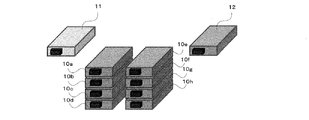
図1に示すように、本実施形態の可搬型バックアップ電源装置は、各ユニットが約0.55kWhの容量を有するリチウムイオン電池で構成され、互いに並列接続された電池ユニット10a〜10hと、これら電池ユニット10a〜10hに接続された充電ユニット11及び放電ユニット12とを備えている。同図に示すように、本実施形態では、4つの電池ユニット10a〜10dを互いに積み重ねて配置されており、また、4つの電池ユニット10e〜10hを互いに積み重ねて配置されている。図には示されていないが、積み重ねられた電池ユニット10a〜10dの上にAC100Vの商用電源をAC/DC変換して充電電流を供給する充電ユニット11が載置されており、積み重ねられた電池ユニット10e〜10hの上に電池ユニットの出力をDC/AC変換してAC100Vの放電電流を出力する放電ユニット12が載置されている。
As shown in FIG. 1, the portable backup power supply device of this embodiment includes
充電ユニット11は、商用電源入力端子の他に、DC12V又は24Vの入力端子及び太陽電池出力の入力端子を有していても良い。単なる一例であるが、電池ユニット10a〜10hの各々は幅約320mm、長さ約506mm、高さ約64mm、重量約12.0kgであり、充電ユニット11は幅約320mm、長さ約512mm、高さ約126.5mm、重量約10.5kgであり、放電ユニット12は幅約320mm、長さ約542mm、高さ約126.5mm、重量約12.0kgである。
The
図2及び図3に示されているように、本実施形態においては、充電ユニット11と電池ユニット10a〜10cとの間にダイオード16a、16c及び16eからなる均等化回路がそれぞれ接続されており、電池ユニット10a〜10cと放電ユニット12との間にダイオード16b、16d及び16fからなる均等化回路がそれぞれ接続されている。図3に示すように、ダイオード16a、16c及び16eは、充電ユニット11から電池ユニット10a〜10cの方向への電流のみを流すようにその向きが設定されており、ダイオード16b、16d及び16fは電池ユニット10a〜10cから放電ユニット12の方向への電流のみを流すようにその向きが設定されている。このようなダイオードを接続することにより、電池残量に起因して電池ユニット間で大電流が流れることを防止できる。即ち、充電側回路及び放電側回路にこのような向きのダイオードを接続することにより、電池電圧の高い電池ユニット10aから電池電圧の低い電池ユニット10bへ大電流が流れることを防止できる。また、電池残量が小さく電池電圧が低い電池ユニット(電池ユニット10b)の充電電流は大きくなり、電池残量が大きく電池電圧が高い電池ユニット(電池ユニット10a)の充電電流は小さくなる。
As shown in FIGS. 2 and 3, in the present embodiment, equalization
なお、図2及び図3においては、一部の電池ユニット10a〜10cのみが示されているが、その他の電池ユニット10d〜10hにも同様に均等化回路が接続されており、同様の作用効果が得られる。
2 and 3, only some of the
以上詳細に説明したように、本実施形態によれば、充電ユニット11と電池ユニット10a〜10cとの間に均等化回路としてダイオード16a、16c及び16eが充電ユニット11から電池ユニット10a〜10cの方向への電流のみを流すようにその向きが設定されてそれぞれ接続されており、電池ユニット10a〜10cと放電ユニット12との間に均等化回路としてダイオード16b、16d及び16fが電池ユニット10a〜10cから放電ユニット12の方向への電流のみを流すようにその向きが設定されてそれぞれ接続されているため、電池電圧の高い電池ユニットから電池電圧の低い電池ユニットへ大電流が流れることを確実に防止でき、安全性が非常に高まる。
As described above in detail, according to the present embodiment, the
図4は本発明の可搬型バックアップ電源装置の他の実施形態におけるシステム構成を概略的に示しており、図5はこの可搬型バックアップ電源装置における均等化回路の機能を概略的に説明しており、図6はこの均等化回路の構成を概略的に示している。 FIG. 4 schematically shows the system configuration of another embodiment of the portable backup power supply device of the present invention, and FIG. 5 schematically explains the function of the equalization circuit in this portable backup power supply device. FIG. 6 schematically shows the configuration of this equalization circuit.
図4には示されていないが、本実施形態においても、図1の実施形態の場合と同様の形態で、互いに並列接続された電池ユニット10a〜10hと、これら電池ユニット10a〜10hに接続された充電及び制御ユニット11′並びに放電ユニット12とが設けられている。これら電池ユニット10a〜10h及び放電ユニット12の構成は、以下に説明する均等化回路を除いて、図1の実施形態の場合と同様であるため、詳細な説明は省略する。
Although not shown in FIG. 4, in the present embodiment as well, the
本実施形態においては、さらに、外部通信モジュール13が設けられており、これら電池ユニット10a〜10h、充電及び制御ユニット11′、放電ユニット12及び外部通信モジュール13は、給電バス14及びユニット間通信バス15に並列に接続されている。また、例えば燃料電池等からなる新たな電池ユニット10iを追加で接続可能となっている。
In the present embodiment, an
本実施形態における充電及び制御ユニット11′は、図1の実施形態における充電ユニット11にバス管理部を設けて構成されており、電池ユニット10a〜10iには、ユニット間通信バス15を介してこのバス管理部と通信する通信用回路がそれぞれ設けられている。後述するように、電池ユニット10a〜10iにはこの可搬型バックアップ電源装置の起動時に実行されるアドレス付与モードにおいて、初めてアドレスが付与されるように構成されている。
The charging and
図4及び図5に示されているように、本実施形態においては、充電及び制御ユニット11′と電池ユニット10a〜10cとの間に定電流コンバータ56a、56c及び56eからなる均等化回路がそれぞれ接続されており、電池ユニット10a〜10cと放電ユニット12との間にダイオード56b、56d及び56fからなる均等化回路がそれぞれ接続されている。図5に示すように、定電流コンバータ56a、56c及び56eは、充電及び制御ユニット11′に設けられたコンピュータ57から通信回線58(ユニット間通信バス15)を介して指示された電流値に電池ユニット10a〜10cへの充電電流をそれぞれ制御する。コンピュータ57は、電池ユニット10a〜10cの電池残量を、ユニット間通信バス15を介した通信によって把握しており、その電池残量に応じて電流値を決定し指示する。ダイオード56b、56d及び56fは電池ユニット10a〜10cから放電ユニット12の方向への電流のみを流すようにその向きが設定されている。このような定電流コンバータ及びダイオードを接続することにより、電池残量に起因して電池ユニット間で大電流が流れることを防止できる。即ち、充電側回路に電流値制御される定電流コンバータを接続することにより、電池ユニットの電池残量が互いに等しくなるように制御され、また、電池電圧の高い電池ユニット10aから電池電圧の低い電池ユニット10bへ大電流が流れることを防止できる。また、電池残量が小さく電池電圧が低い電池ユニット(電池ユニット10b)の充電電流は大きくなり、電池残量が大きく電池電圧が高い電池ユニット(電池ユニット10a)の充電電流は小さくなる。さらに、放電側回路に上述のような向きのダイオードを接続することにより、電池電圧の高い電池ユニット10aから電池電圧の低い電池ユニット10bへ大電流が流れることを防止できる。さらにまた、電池残量が小さく電池電圧が低い電池ユニット(電池ユニット10b)の放電電流は小さくなり、電池残量が大きく電池電圧が高い電池ユニット(電池ユニット10a)の放電電流は大きくなる。
As shown in FIGS. 4 and 5, in the present embodiment, equalization circuits including constant
なお、図4及び図5においては、一部の電池ユニット10a〜10cのみが示されているが、その他の電池ユニット10d〜10hにも同様に均等化回路が接続されており、同様の作用効果が得られる。
4 and 5, only some of the
均等化回路として、定電流コンバータを用いることにより、ダイオードを用いた場合の順方向降下電圧(0.5〜1.0V程度)による損失を防ぐことができる。 By using a constant current converter as the equalizing circuit, it is possible to prevent a loss due to a forward voltage drop (about 0.5 to 1.0 V) when a diode is used.
なお、放電側の均等化回路として、電流値制御される定電流コンバータを設けても良いことはもちろんである。 Of course, a constant current converter whose current value is controlled may be provided as an equalizing circuit on the discharge side.
図7は本実施形態の可搬型バックアップ電源装置における通信バスを用いた通信回路構成の一例を概略的に示しており、図8はこの通信回路構成におけるアドレス付与回路の構成を概略的に示しており、図9はこのアドレス付与回路におけるアドレス付与動作のタイムチャート及びフローを示している。 FIG. 7 schematically shows an example of a communication circuit configuration using a communication bus in the portable backup power supply device of this embodiment, and FIG. 8 schematically shows the configuration of an address assignment circuit in this communication circuit configuration. FIG. 9 shows a time chart and a flow of the address assigning operation in this address assigning circuit.
図7に示すバス管理部70は充電及び制御ユニット10′内に設けられており、このバス管理部70と、例えば電池ユニット10aの通信用回路72とはユニット間通信バス15のデータ送受用バス71を介してデータの送受信を行えるように構成されている。バス管理部70には、コンピュータ57の基板70aと、全二重方式のドライバ70bとが設けられており、コンピュータ57は基板70a及びドライバ70bを介してデータ送受用バス71に接続されている。電池ユニット10aの通信用回路72には、全二重方式のドライバ72aと、コンピュータ72bと、電池ユニット10aの電池残量を検出する回路に相当する電池電圧測定部72cと、アドレス付与用のフリップフロップ72dとが設けられている。電池ユニット10bの通信用回路73には、全二重方式のドライバ73aと、コンピュータ73bと、電池ユニット10bの電池電圧測定部73cと、アドレス付与用のフリップフロップ73dとが設けられている。他の電池ユニットにおいても、同様の通信用回路が設けられている。
The
前述したように、本実施形態における電池ユニット10a〜10iはあらかじめ決められた固有アドレスを持っておらず、これら電池ユニット10a〜10iは、給電バス14及びユニット間通信バス15に接続された後、充電及び制御ユニット11′のバス管理部70によってアドレスが付与される。アドレスが付与された後、これら電池ユニット10a〜10iは付与されたアドレスを用いてデータの送受信を行う。また、このアドレス付与により、バス管理部70は、電池ユニットが何台接続されているかも含めて、接続されている電池ユニットを確実に把握することができる。
As described above, the
次に、各電池ユニットのアドレス付与動作について説明する。 Next, the address assignment operation of each battery unit will be described.
図8に示すように、ユニット間通信バス15のアドレス付与用制御線77は、基板70aのGPIO1〜GPIO4端子に接続されており、このアドレス付与用制御線77には、各電池ユニットのアドレス付与用のフリップフロップ72d〜76dが接続されている。
As shown in FIG. 8, the address
図9(A)に示すように、バス管理部70のコンピュータ57は、GPIO1〜GPIO3端子の電圧を制御して各電池ユニットのアドレス付与用のフリップフロップ(D型フリップフロップ)72d〜76dのQ出力EN1〜EN5を順次レベル「1」として行く。Q出力がレベル「1」となるとその電池ユニットはバス管理部70と通信することが可能となる。例えば、Q出力EN1がレベル「1」となるとその電池ユニット10aの通信用回路72は、基板70aのDI、DO、RO及びR/E端子に接続されている接続データ送受用バス71を使用してバス管理部70と通信することが可能となる。この状態で、バス管理部70からその電池ユニットについてアドレスが付与される。同様にして全ての電池ユニットに対してアドレスが付与され、終端の電池ユニットにアドレスが付与されると、GPIO4端子の制御線がレベル「0」からレベル「1」となるため、バス管理部70は、全ての電池ユニットにアドレスが付与されたことを知ることができ、また、接続されている電池ユニットの数を知ることができる。
As shown in FIG. 9A, the
図9(B)は以上述べたアドレス付与の処理フローを説明している。即ち、電池ユニットnのQ出力ENnがレベル「1」(High)の間にこの電池ユニットnがアドレス付与を請求し、バス管理部70がアドレスを付与し、電池ユニットnがアクノレッジ(ACK)を行うという手順でアドレス付与が行われる。
FIG. 9B illustrates the processing flow of address assignment described above. That is, while the Q output ENn of the battery unit n is level “1” (High), the battery unit n requests address assignment, the
次に、以上のごとくしてアドレスが付与された電池ユニットnとバス管理部70との間の、例えば電池残量、定電流コンバータの設定電流値等のデータの送受信について、図10を参照して説明する。通信プロトコルとしては、例えば、非同期のスタートストップ方式が用いられる。
Next, refer to FIG. 10 for data transmission / reception between the battery unit n to which the address is assigned as described above and the
図10(A)はバス管理部70から電池ユニットnへのデータ送信の処理フローを示している。まず、バス管理部70から電池ユニットnへアドレスnとコマンドとを送付し、電池ユニットnはACKを返す。次いで、バス管理部70から電池ユニットnへmバイトのデータ、例えばその電池ユニットの定電流コンバータの設定電流値データを送付し、電池ユニットnはACKを返す。
FIG. 10A shows a processing flow of data transmission from the
図10(B)はバス管理部70から電池ユニットnへのデータ請求の処理フローを示している。まず、バス管理部70から電池ユニットnへアドレスnとコマンドとを送付し、電池ユニットnはACKを返す。次いで、電池ユニットnからバス管理部70へmバイトのデータ、例えばその電池ユニットの電池残量データを送付し、バス管理部70はACKを返す。
FIG. 10B shows a processing flow for requesting data from the
図10(C)は電池ユニットnからバス管理部70へのデータ送信の処理フローを示している。まず、電池ユニットnからバス管理部70へアドレス0と送付データ数とを送付し、バス管理部70はACKを返す。次いで、電池ユニットnからバス管理部70へmバイトのデータ、例えばその電池ユニットの電池残量データを送付し、バス管理部70はACKを返す。その後、電池ユニットnからバス管理部70へ1バイトのチェックサムを送付し、バス管理部70はACK又はNACKを返す。
FIG. 10C shows a processing flow of data transmission from the battery unit n to the
なお、以上の説明では、ユニット間通信バス72のドライバ70b、71aとして全二重方式のドライバを用いているが、これに代えて半二重方式のドライバを用いても良いことは明らかである。
In the above description, full-duplex drivers are used as the
以上詳細に説明したように、本実施形態によれば、充電及び制御ユニット11′と電池ユニット10a〜10cとの間に均等化回路として電池残量によって電流値が設定される定電流コンバータ56a、56c及び56eがそれぞれ接続されており、電池ユニット10a〜10cと放電ユニット12との間に均等化回路としてダイオード16b、16d及び16fが電池ユニット10a〜10cから放電ユニット12の方向への電流のみを流すようにその向きが設定されてそれぞれ接続されているため、電池電圧の高い電池ユニットから電池電圧の低い電池ユニットへ大電流が流れることを確実に防止でき、安全性が非常に高まる。さらに、定電流コンバータ56a、56c及び56eにより、充電時は電池残量がそろうように均等化充電される。また、本実施形態によれば、電池ユニットは固有アドレスを有しておらず、接続された後にアドレス付与が行われるため、電池ユニットが何台接続されているかも含めて、接続されている電池ユニットを確実に把握することができる。
As described above in detail, according to the present embodiment, the constant
以上述べた実施形態は全て本発明を例示的に示すものであって限定的に示すものではなく、本発明は他の種々の変形態様及び変更態様で実施することができる。従って本発明の範囲は特許請求の範囲及びその均等範囲によってのみ規定されるものである。 All the embodiments described above are illustrative of the present invention and are not intended to be limiting, and the present invention can be implemented in other various modifications and changes. Therefore, the scope of the present invention is defined only by the claims and their equivalents.
10a〜10i 電池ユニット
11 充電ユニット
11′ 充電及び制御ユニット
12 放電ユニット
13 外部通信モジュール
14 給電バス
15 ユニット間通信バス
16a〜16f、56b、56d、56f ダイオード
56a〜56c 定電流コンバータ
57、72b、73b コンピュータ
58 通信回線
70 バス管理部
71 データ送受用バス
70a 基板
70b、72a、73a 全二重方式のドライバ
72 通信用回路
72c、73c 電池電圧測定部
72d〜76d フリップフロップ
77 アドレス付与用制御線
10a to
Claims (6)
Priority Applications (1)
| Application Number | Priority Date | Filing Date | Title |
|---|---|---|---|
| JP2016057909A JP6824616B2 (en) | 2016-03-23 | 2016-03-23 | Portable backup power supply |
Applications Claiming Priority (1)
| Application Number | Priority Date | Filing Date | Title |
|---|---|---|---|
| JP2016057909A JP6824616B2 (en) | 2016-03-23 | 2016-03-23 | Portable backup power supply |
Publications (2)
| Publication Number | Publication Date |
|---|---|
| JP2017175744A true JP2017175744A (en) | 2017-09-28 |
| JP6824616B2 JP6824616B2 (en) | 2021-02-03 |
Family
ID=59973425
Family Applications (1)
| Application Number | Title | Priority Date | Filing Date |
|---|---|---|---|
| JP2016057909A Active JP6824616B2 (en) | 2016-03-23 | 2016-03-23 | Portable backup power supply |
Country Status (1)
| Country | Link |
|---|---|
| JP (1) | JP6824616B2 (en) |
Cited By (1)
| Publication number | Priority date | Publication date | Assignee | Title |
|---|---|---|---|---|
| KR20200000182A (en) * | 2018-06-22 | 2020-01-02 | 주식회사 엘지화학 | Apparatus and method for operating battery |
Citations (13)
| Publication number | Priority date | Publication date | Assignee | Title |
|---|---|---|---|---|
| JPH11191933A (en) * | 1997-10-20 | 1999-07-13 | Fujitsu Ltd | Battery charging device and method and electronic equipment |
| JP2000032683A (en) * | 1994-09-01 | 2000-01-28 | Fujitsu Ltd | Charge control device, constant-voltage constant- current control circuit, charge device, electronic equipment, and device and control circuit for charging plural chargeable batteries |
| JP2003209932A (en) * | 2002-01-10 | 2003-07-25 | Panasonic Ev Energy Co Ltd | Battery power supply unit and control method and address setting method therefor |
| JP2004260905A (en) * | 2003-02-25 | 2004-09-16 | Yanmar Co Ltd | Hybrid system |
| JP2004304983A (en) * | 2003-04-01 | 2004-10-28 | Canon Inc | General-purposed charger |
| JP2006345660A (en) * | 2005-06-09 | 2006-12-21 | Sony Corp | Power supply |
| JP2009089486A (en) * | 2007-09-28 | 2009-04-23 | Hitachi Ltd | Multiple series battery control system |
| JP3172514U (en) * | 2011-10-11 | 2011-12-22 | 株式会社 データ総研 | Emergency portable power supply |
| US20120262121A1 (en) * | 2011-04-15 | 2012-10-18 | Simplo Technology Co., Ltd. | Battery balancing circuit and balancing method thereof and battery activation method |
| JP2013078242A (en) * | 2011-09-30 | 2013-04-25 | Sanyo Electric Co Ltd | Electric power supply device |
| JP2014124064A (en) * | 2012-12-21 | 2014-07-03 | Sekisui Chem Co Ltd | Power storage system, and cartridge |
| JP2015156793A (en) * | 2013-03-18 | 2015-08-27 | 株式会社日立製作所 | Battery system and battery monitoring device |
| JP2016034170A (en) * | 2012-12-27 | 2016-03-10 | 三洋電機株式会社 | Power storage device charge/discharge system |
-
2016
- 2016-03-23 JP JP2016057909A patent/JP6824616B2/en active Active
Patent Citations (14)
| Publication number | Priority date | Publication date | Assignee | Title |
|---|---|---|---|---|
| JP2000032683A (en) * | 1994-09-01 | 2000-01-28 | Fujitsu Ltd | Charge control device, constant-voltage constant- current control circuit, charge device, electronic equipment, and device and control circuit for charging plural chargeable batteries |
| JP2003037946A (en) * | 1994-09-01 | 2003-02-07 | Fujitsu Ltd | Electronic equipment and charge/discharge control device |
| JPH11191933A (en) * | 1997-10-20 | 1999-07-13 | Fujitsu Ltd | Battery charging device and method and electronic equipment |
| JP2003209932A (en) * | 2002-01-10 | 2003-07-25 | Panasonic Ev Energy Co Ltd | Battery power supply unit and control method and address setting method therefor |
| JP2004260905A (en) * | 2003-02-25 | 2004-09-16 | Yanmar Co Ltd | Hybrid system |
| JP2004304983A (en) * | 2003-04-01 | 2004-10-28 | Canon Inc | General-purposed charger |
| JP2006345660A (en) * | 2005-06-09 | 2006-12-21 | Sony Corp | Power supply |
| JP2009089486A (en) * | 2007-09-28 | 2009-04-23 | Hitachi Ltd | Multiple series battery control system |
| US20120262121A1 (en) * | 2011-04-15 | 2012-10-18 | Simplo Technology Co., Ltd. | Battery balancing circuit and balancing method thereof and battery activation method |
| JP2013078242A (en) * | 2011-09-30 | 2013-04-25 | Sanyo Electric Co Ltd | Electric power supply device |
| JP3172514U (en) * | 2011-10-11 | 2011-12-22 | 株式会社 データ総研 | Emergency portable power supply |
| JP2014124064A (en) * | 2012-12-21 | 2014-07-03 | Sekisui Chem Co Ltd | Power storage system, and cartridge |
| JP2016034170A (en) * | 2012-12-27 | 2016-03-10 | 三洋電機株式会社 | Power storage device charge/discharge system |
| JP2015156793A (en) * | 2013-03-18 | 2015-08-27 | 株式会社日立製作所 | Battery system and battery monitoring device |
Cited By (2)
| Publication number | Priority date | Publication date | Assignee | Title |
|---|---|---|---|---|
| KR20200000182A (en) * | 2018-06-22 | 2020-01-02 | 주식회사 엘지화학 | Apparatus and method for operating battery |
| KR102603205B1 (en) | 2018-06-22 | 2023-11-15 | 주식회사 엘지에너지솔루션 | Apparatus and method for operating battery |
Also Published As
| Publication number | Publication date |
|---|---|
| JP6824616B2 (en) | 2021-02-03 |
Similar Documents
| Publication | Publication Date | Title |
|---|---|---|
| US9780591B2 (en) | Adaptive battery pack | |
| EP2608347A2 (en) | Electric energy storage system and method of maintaining the same | |
| US20140210419A1 (en) | Battery pack and method for minimizing cell voltage deviations | |
| EP2610993A1 (en) | Power supply device | |
| JP5543014B2 (en) | Communication system and storage battery system | |
| WO2011143158A2 (en) | Battery charging using multiple chargers | |
| WO2016121273A1 (en) | Power control device, power control method, and power control system | |
| US11018382B2 (en) | System and method for assigning unique number to cell module controller | |
| JP2018523959A (en) | Electric vehicle charging station and method for controlling an electric vehicle charging station | |
| KR20150013302A (en) | Charge balancing in a battery | |
| JP2008235032A (en) | Communication control system of packed batteries, its battery pack, and its communication control method | |
| WO2012124221A1 (en) | Communication system, and rechargeable battery system | |
| WO2012157475A1 (en) | Power supply system, method for setting identification information of power supply system, and battery unit | |
| KR20130053885A (en) | Battery management system and battery pack protection apparatus including the same | |
| JP2016171470A (en) | Communication device, reception device and communication system | |
| JP2016073009A (en) | Power storage system and control device | |
| BR102016011925B1 (en) | method for self-registration and / or self-assembly of a plurality of electrical devices | |
| JP6824616B2 (en) | Portable backup power supply | |
| JP6974272B2 (en) | Power supply, power supply control, power supply control method, and power supply system | |
| JP2016111904A (en) | Charging system with enhanced charging efficiency, and charging device and power storage equipment | |
| CN106410838B (en) | Power supply system including energy storage system | |
| CN114256956B (en) | DC power supply system | |
| CN106557144B (en) | Direct current healthcare facilities | |
| US9620977B2 (en) | Battery device for a scalable power system | |
| WO2015075415A1 (en) | Charging bus |
Legal Events
| Date | Code | Title | Description |
|---|---|---|---|
| A80 | Written request to apply exceptions to lack of novelty of invention |
Free format text: JAPANESE INTERMEDIATE CODE: A80 Effective date: 20160330 |
|
| A621 | Written request for application examination |
Free format text: JAPANESE INTERMEDIATE CODE: A621 Effective date: 20190116 |
|
| A977 | Report on retrieval |
Free format text: JAPANESE INTERMEDIATE CODE: A971007 Effective date: 20191021 |
|
| A131 | Notification of reasons for refusal |
Free format text: JAPANESE INTERMEDIATE CODE: A131 Effective date: 20191119 |
|
| A521 | Request for written amendment filed |
Free format text: JAPANESE INTERMEDIATE CODE: A523 Effective date: 20191227 |
|
| A131 | Notification of reasons for refusal |
Free format text: JAPANESE INTERMEDIATE CODE: A131 Effective date: 20200526 |
|
| A521 | Request for written amendment filed |
Free format text: JAPANESE INTERMEDIATE CODE: A523 Effective date: 20200710 |
|
| TRDD | Decision of grant or rejection written | ||
| A01 | Written decision to grant a patent or to grant a registration (utility model) |
Free format text: JAPANESE INTERMEDIATE CODE: A01 Effective date: 20210105 |
|
| A61 | First payment of annual fees (during grant procedure) |
Free format text: JAPANESE INTERMEDIATE CODE: A61 Effective date: 20210113 |
|
| R150 | Certificate of patent or registration of utility model |
Ref document number: 6824616 Country of ref document: JP Free format text: JAPANESE INTERMEDIATE CODE: R150 |
|
| S533 | Written request for registration of change of name |
Free format text: JAPANESE INTERMEDIATE CODE: R313533 |
|
| R350 | Written notification of registration of transfer |
Free format text: JAPANESE INTERMEDIATE CODE: R350 |
|
| R250 | Receipt of annual fees |
Free format text: JAPANESE INTERMEDIATE CODE: R250 |