JP2017175686A - Wiring harness - Google Patents
Wiring harness Download PDFInfo
- Publication number
- JP2017175686A JP2017175686A JP2016056409A JP2016056409A JP2017175686A JP 2017175686 A JP2017175686 A JP 2017175686A JP 2016056409 A JP2016056409 A JP 2016056409A JP 2016056409 A JP2016056409 A JP 2016056409A JP 2017175686 A JP2017175686 A JP 2017175686A
- Authority
- JP
- Japan
- Prior art keywords
- branch
- wire harness
- line
- conductive path
- shield
- Prior art date
- Legal status (The legal status is an assumption and is not a legal conclusion. Google has not performed a legal analysis and makes no representation as to the accuracy of the status listed.)
- Granted
Links
- 239000004020 conductor Substances 0.000 claims abstract description 37
- 238000009413 insulation Methods 0.000 claims abstract description 32
- 238000004078 waterproofing Methods 0.000 claims abstract description 25
- 229920005989 resin Polymers 0.000 claims description 30
- 239000011347 resin Substances 0.000 claims description 30
- 230000001012 protector Effects 0.000 claims description 22
- 238000000034 method Methods 0.000 claims description 16
- 238000000576 coating method Methods 0.000 abstract description 2
- 230000000694 effects Effects 0.000 description 17
- 239000012212 insulator Substances 0.000 description 11
- 229910052751 metal Inorganic materials 0.000 description 9
- 239000002184 metal Substances 0.000 description 9
- 238000000465 moulding Methods 0.000 description 4
- 229920005992 thermoplastic resin Polymers 0.000 description 4
- 229910052782 aluminium Inorganic materials 0.000 description 3
- XAGFODPZIPBFFR-UHFFFAOYSA-N aluminium Chemical compound [Al] XAGFODPZIPBFFR-UHFFFAOYSA-N 0.000 description 3
- 239000011888 foil Substances 0.000 description 3
- 238000009940 knitting Methods 0.000 description 3
- 239000000463 material Substances 0.000 description 3
- 238000005192 partition Methods 0.000 description 3
- 230000002093 peripheral effect Effects 0.000 description 3
- RYGMFSIKBFXOCR-UHFFFAOYSA-N Copper Chemical compound [Cu] RYGMFSIKBFXOCR-UHFFFAOYSA-N 0.000 description 2
- 229910000881 Cu alloy Inorganic materials 0.000 description 2
- 239000004743 Polypropylene Substances 0.000 description 2
- XUIMIQQOPSSXEZ-UHFFFAOYSA-N Silicon Chemical compound [Si] XUIMIQQOPSSXEZ-UHFFFAOYSA-N 0.000 description 2
- 229910052802 copper Inorganic materials 0.000 description 2
- 239000010949 copper Substances 0.000 description 2
- 229920013716 polyethylene resin Polymers 0.000 description 2
- 239000002861 polymer material Substances 0.000 description 2
- -1 polypropylene Polymers 0.000 description 2
- 229920001155 polypropylene Polymers 0.000 description 2
- 239000004800 polyvinyl chloride Substances 0.000 description 2
- 229920000915 polyvinyl chloride Polymers 0.000 description 2
- 229910052710 silicon Inorganic materials 0.000 description 2
- 239000010703 silicon Substances 0.000 description 2
- 229910000838 Al alloy Inorganic materials 0.000 description 1
- 229910018095 Ni-MH Inorganic materials 0.000 description 1
- 229910018477 Ni—MH Inorganic materials 0.000 description 1
- 239000003990 capacitor Substances 0.000 description 1
- 239000011248 coating agent Substances 0.000 description 1
- 238000010586 diagram Methods 0.000 description 1
- 239000003822 epoxy resin Substances 0.000 description 1
- 238000003780 insertion Methods 0.000 description 1
- 230000037431 insertion Effects 0.000 description 1
- 230000010354 integration Effects 0.000 description 1
- 229910001416 lithium ion Inorganic materials 0.000 description 1
- 238000012856 packing Methods 0.000 description 1
- 229920000647 polyepoxide Polymers 0.000 description 1
- 238000007789 sealing Methods 0.000 description 1
- 238000003466 welding Methods 0.000 description 1
Images


Classifications
-
- H—ELECTRICITY
- H01—ELECTRIC ELEMENTS
- H01B—CABLES; CONDUCTORS; INSULATORS; SELECTION OF MATERIALS FOR THEIR CONDUCTIVE, INSULATING OR DIELECTRIC PROPERTIES
- H01B7/00—Insulated conductors or cables characterised by their form
- H01B7/0045—Cable-harnesses
-
- B—PERFORMING OPERATIONS; TRANSPORTING
- B60—VEHICLES IN GENERAL
- B60R—VEHICLES, VEHICLE FITTINGS, OR VEHICLE PARTS, NOT OTHERWISE PROVIDED FOR
- B60R16/00—Electric or fluid circuits specially adapted for vehicles and not otherwise provided for; Arrangement of elements of electric or fluid circuits specially adapted for vehicles and not otherwise provided for
- B60R16/02—Electric or fluid circuits specially adapted for vehicles and not otherwise provided for; Arrangement of elements of electric or fluid circuits specially adapted for vehicles and not otherwise provided for electric constitutive elements
- B60R16/0207—Wire harnesses
- B60R16/0215—Protecting, fastening and routing means therefor
-
- H—ELECTRICITY
- H01—ELECTRIC ELEMENTS
- H01B—CABLES; CONDUCTORS; INSULATORS; SELECTION OF MATERIALS FOR THEIR CONDUCTIVE, INSULATING OR DIELECTRIC PROPERTIES
- H01B7/00—Insulated conductors or cables characterised by their form
- H01B7/009—Cables with built-in connecting points or with predetermined areas for making deviations
-
- H—ELECTRICITY
- H01—ELECTRIC ELEMENTS
- H01B—CABLES; CONDUCTORS; INSULATORS; SELECTION OF MATERIALS FOR THEIR CONDUCTIVE, INSULATING OR DIELECTRIC PROPERTIES
- H01B7/00—Insulated conductors or cables characterised by their form
- H01B7/17—Protection against damage caused by external factors, e.g. sheaths or armouring
- H01B7/28—Protection against damage caused by moisture, corrosion, chemical attack or weather
- H01B7/282—Preventing penetration of fluid, e.g. water or humidity, into conductor or cable
-
- H—ELECTRICITY
- H01—ELECTRIC ELEMENTS
- H01R—ELECTRICALLY-CONDUCTIVE CONNECTIONS; STRUCTURAL ASSOCIATIONS OF A PLURALITY OF MUTUALLY-INSULATED ELECTRICAL CONNECTING ELEMENTS; COUPLING DEVICES; CURRENT COLLECTORS
- H01R4/00—Electrically-conductive connections between two or more conductive members in direct contact, i.e. touching one another; Means for effecting or maintaining such contact; Electrically-conductive connections having two or more spaced connecting locations for conductors and using contact members penetrating insulation
- H01R4/70—Insulation of connections
-
- H—ELECTRICITY
- H01—ELECTRIC ELEMENTS
- H01R—ELECTRICALLY-CONDUCTIVE CONNECTIONS; STRUCTURAL ASSOCIATIONS OF A PLURALITY OF MUTUALLY-INSULATED ELECTRICAL CONNECTING ELEMENTS; COUPLING DEVICES; CURRENT COLLECTORS
- H01R4/00—Electrically-conductive connections between two or more conductive members in direct contact, i.e. touching one another; Means for effecting or maintaining such contact; Electrically-conductive connections having two or more spaced connecting locations for conductors and using contact members penetrating insulation
- H01R4/10—Electrically-conductive connections between two or more conductive members in direct contact, i.e. touching one another; Means for effecting or maintaining such contact; Electrically-conductive connections having two or more spaced connecting locations for conductors and using contact members penetrating insulation effected solely by twisting, wrapping, bending, crimping, or other permanent deformation
- H01R4/18—Electrically-conductive connections between two or more conductive members in direct contact, i.e. touching one another; Means for effecting or maintaining such contact; Electrically-conductive connections having two or more spaced connecting locations for conductors and using contact members penetrating insulation effected solely by twisting, wrapping, bending, crimping, or other permanent deformation by crimping
- H01R4/20—Electrically-conductive connections between two or more conductive members in direct contact, i.e. touching one another; Means for effecting or maintaining such contact; Electrically-conductive connections having two or more spaced connecting locations for conductors and using contact members penetrating insulation effected solely by twisting, wrapping, bending, crimping, or other permanent deformation by crimping using a crimping sleeve
-
- H—ELECTRICITY
- H01—ELECTRIC ELEMENTS
- H01R—ELECTRICALLY-CONDUCTIVE CONNECTIONS; STRUCTURAL ASSOCIATIONS OF A PLURALITY OF MUTUALLY-INSULATED ELECTRICAL CONNECTING ELEMENTS; COUPLING DEVICES; CURRENT COLLECTORS
- H01R4/00—Electrically-conductive connections between two or more conductive members in direct contact, i.e. touching one another; Means for effecting or maintaining such contact; Electrically-conductive connections having two or more spaced connecting locations for conductors and using contact members penetrating insulation
- H01R4/58—Electrically-conductive connections between two or more conductive members in direct contact, i.e. touching one another; Means for effecting or maintaining such contact; Electrically-conductive connections having two or more spaced connecting locations for conductors and using contact members penetrating insulation characterised by the form or material of the contacting members
- H01R4/62—Connections between conductors of different materials; Connections between or with aluminium or steel-core aluminium conductors
Abstract
Description
本発明は、導電路を備えて高電圧の機器間を電気的に接続するワイヤハーネスに関する。 The present invention relates to a wire harness that includes a conductive path and electrically connects high-voltage devices.
ハイブリッド自動車や電気自動車に搭載される高電圧の機器間(補器間)を電気的に接続するための従来のワイヤハーネスとしては、例えば下記特許文献1に開示されたものが知られる。ワイヤハーネスは、一又は複数本の導電路と、この導電路を収容保護する外装部材と、ハーネス端末に配設されて外部の高電圧の機器との接続を行う外部接続手段と、ワイヤハーネスを固定対象に取り付け固定するための複数の固定部材とを備えて構成される。
As a conventional wire harness for electrically connecting high-voltage devices (between auxiliary devices) mounted on a hybrid vehicle or an electric vehicle, for example, one disclosed in
上記従来のワイヤハーネスにあっては、接続対象になる機器(補器)がエンジンルームのインバータユニット及び自動車後部のバッテリーであり、本願発明者は、例えばこれら二つに加え、新たに別な機器(補器)に対しても電気的な接続をすることができるようにしたいと考えている。そこで、ワイヤハーネスにおけるエンジンルーム側のハーネス端末から別な機器まで導電路をのばす構造を検討してみたが、恰も導電路をUターンさせるような状態の配索になることから、作業が繁雑になってしまうという問題点を有する。また、別な機器に対してハーネス端末から導電路をのばすことが最短になるとは限らず、Uターンさせた分だけ導電路が長尺になって、結果、コストが嵩んでしまうという問題点も有する。 In the above-described conventional wire harness, the devices (auxiliary devices) to be connected are the inverter unit in the engine room and the battery at the rear of the vehicle. I would like to be able to make electrical connections to (auxiliary devices). Therefore, I examined the structure that extends the conductive path from the harness terminal on the engine room side to another device in the wire harness, but the work is complicated because the wiring is in a state that makes the conductive path U-turn. It has the problem of becoming. In addition, extending the conductive path from the harness terminal to another device is not always the shortest, and the conductive path becomes long as much as the U-turn is made, resulting in an increase in cost. Have.
本発明は、上記した事情に鑑みてなされたもので、機器との接続に関し作業性向上及びコスト低減を図ることが可能なワイヤハーネスを提供することを課題とする。 This invention is made | formed in view of an above-described situation, and makes it a subject to provide the wire harness which can aim at workability | operativity improvement and cost reduction regarding the connection with an apparatus.
上記課題を解決するためになされた請求項1に記載の本発明のワイヤハーネスは、導電路を備えて高電圧の機器間を電気的に接続するワイヤハーネスにおいて、前記導電路を幹線として用い、且つ、該幹線から分岐するための分岐線を更に備え、前記幹線及び前記分岐線のそれぞれ所定位置の被覆を除去して幹線側導体露出部及び分岐線側導体露出部を形成するとともに、前記幹線側導体露出部及び前記分岐線側導体露出部を接続して分岐接続部を形成し、該分岐接続部に対しては絶縁処理及び防水処理の部分として機能する絶縁防水処理部を設けることを特徴とする。
The wire harness of the present invention according to
請求項2に記載の本発明は、請求項1に記載のワイヤハーネスにおいて、前記絶縁防水処理部を覆ってシールド処理を施すシールド処理部材を更に備えることを特徴とする。 According to a second aspect of the present invention, in the wire harness according to the first aspect of the present invention, the wire harness further includes a shield processing member that covers the insulating waterproof processing portion and performs a shield process.
請求項3に記載の本発明は、請求項2に記載のワイヤハーネスにおいて、前記シールド処理部材にて覆われた前記絶縁防水処理部を収容するプロテクタを更に備えることを特徴とする。 According to a third aspect of the present invention, in the wire harness according to the second aspect of the present invention, the wire harness further includes a protector that accommodates the insulating waterproof processing portion covered with the shield processing member.
請求項4に記載の本発明は、請求項1、2又は3に記載のワイヤハーネスにおいて、前記絶縁防水処理部の一部又は全部を樹脂モールドにより形成することを特徴とする。 According to a fourth aspect of the present invention, in the wire harness according to the first, second, or third aspect, a part or all of the insulating waterproofing portion is formed by a resin mold.
以上のような特徴を有する本発明によれば、導電路を幹線として用い、そして、この幹線である導電路の途中に分岐線を接続する構造のワイヤハーネスになる。幹線としての導電路と分岐線との接続部分(分岐接続部)には、絶縁防水処理部が設けられて絶縁処理及び防水処理が施された状態になることから、高電圧のワイヤハーネスであっても分岐に関し問題が生じることはない。また、本発明によれば、絶縁防水処理部の一部又は全部が樹脂モールドにより形成されることから、分岐接続部が埋まった状態になり、結果、絶縁性や防水性が向上するのは勿論である。この他、本発明によれば、シールド処理部材を更に備えることから、絶縁防水処理部を覆ってシールド処理を施すことが可能になる。また、プロテクタを更に備えることから、シールド処理部材にて覆われた絶縁防水処理部を収容して外部から保護をすることが可能になる。プロテクタを用いることで、分岐の部分があってもワイヤハーネスの配索がし易くなるのは勿論である。本発明は、例えば車両床下を通って配索される長尺なワイヤハーネスに採用されることが好適である。 According to the present invention having the above-described features, a wire harness having a structure in which a conductive path is used as a trunk line and a branch line is connected to the middle of the conductive path which is the trunk line. The connection part (branch connection part) between the conductive path as the trunk line and the branch line is provided with an insulation waterproof treatment part and is subjected to insulation treatment and waterproof treatment, so that it is a high voltage wire harness. However, there is no problem with branching. In addition, according to the present invention, part or all of the insulating waterproofing processing part is formed of a resin mold, so that the branch connection part is buried, and as a result, the insulation and waterproofing are improved. It is. In addition, according to the present invention, since the shield processing member is further provided, it is possible to cover the insulating waterproof processing portion and perform the shield processing. Further, since the protector is further provided, it is possible to protect from the outside by accommodating the insulating waterproof processing part covered with the shield processing member. Of course, by using the protector, the wiring harness can be easily routed even if there is a branching portion. The present invention is preferably employed in a long wire harness that is routed, for example, under the vehicle floor.
請求項1に記載された本発明によれば、途中から分岐線がのびるワイヤハーネスであることから、ハーネス端末位置から恰も導電路をUターンさせるようなものではなく、また、必要最低限の長さで済ませることができる。従って、本発明によれば、機器(補器)との接続に関し作業性向上及びコスト低減を図ることができるという効果を奏する。本発明のワイヤハーネスの提供により、ハーネス端末位置の機器(補器)同士の電気的な接続のみならず別な機器(補器)との接続も図ることができるという効果を奏する。 According to the first aspect of the present invention, since it is a wire harness in which a branch line extends from the middle, it is not a thing that makes the conductive path U-turn from the position of the harness terminal. You can do it. Therefore, according to this invention, there exists an effect that workability | operativity improvement and cost reduction can be aimed at regarding a connection with an apparatus (auxiliary device). By providing the wire harness of the present invention, there is an effect that not only electrical connection between devices (auxiliary devices) at the harness terminal position but also connection with another device (auxiliary device) can be achieved.
請求項2に記載された本発明によれば、請求項1の効果に加え次のような効果を更に奏する。すなわち、分岐線を分岐する分岐接続部に対しシールド性を持たせることができるという効果を奏する。
According to the present invention described in
請求項3に記載された本発明によれば、請求項2の効果に加え次のような効果を更に奏する。すなわち、シールド処理部材にて覆われた絶縁防水処理部をプロテクタに収容することで、分岐線がのびるワイヤハーネスであってもプロテクタを介して配索先に簡単に固定することができるという効果を奏する。これにより、配索に係る作業性を向上させることができるという効果を奏する。
According to the present invention described in claim 3, in addition to the effect of
請求項4に記載された本発明によれば、請求項1、2又は3の効果に加え次のような効果を更に奏する。すなわち、樹脂モールドにより絶縁防水処理部の一部又は全部を形成することから、分岐接続部が恰も埋まった状態になり、結果、絶縁性や防水性を向上させることができるという効果を奏する。
According to the present invention described in
ワイヤハーネスは、導電路を備えて高電圧の機器間を電気的に接続するものであり、導電路が幹線として用いられる。そして、この幹線である導電路の途中に分岐線が接続される。幹線及び分岐線は、それぞれ所定位置の被覆が除去されて幹線側導体露出部及び分岐線側導体露出部が形成される。この幹線側導体露出部及び分岐線側導体露出部が接続されると、分岐接続部が形成される。分岐接続部に対しては、絶縁処理及び防水処理の部分として機能する絶縁防水処理部が設けられる。 The wire harness is provided with a conductive path to electrically connect high-voltage devices, and the conductive path is used as a trunk line. A branch line is connected in the middle of the conductive path which is the trunk line. The trunk line and the branch line are respectively removed from the coating at predetermined positions to form a trunk line side conductor exposed portion and a branch line side conductor exposed portion. When the trunk line side conductor exposed portion and the branch line side conductor exposed portion are connected, a branch connection portion is formed. For the branch connection portion, an insulating waterproof processing portion that functions as a portion of the insulating processing and waterproof processing is provided.
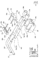
以下、図面を参照しながら実施例1を説明する。図1は本発明のワイヤハーネスの配索状態を示す模式図である。また、図2は図1の分岐構造部本体の分解斜視図、図3は図2の分岐接続部及び絶縁防水処理部の分解斜視図、図4は分岐接続部及び絶縁防水処理部の平面図(樹脂モールド前)、図5は図4の断面図、図6は分岐接続部及び絶縁防水処理部の樹脂モールド前後の斜視図である。
本実施例においては、ハイブリッド自動車(電気自動車等であってもよい)に配索されるワイヤハーネスに対し本発明を採用する。 In the present embodiment, the present invention is adopted for a wire harness routed in a hybrid vehicle (which may be an electric vehicle or the like).
<ハイブリッド自動車1について>
図1において、引用符号1はハイブリッド自動車を示す。ハイブリッド自動車1は、エンジン2及びモータユニット3の二つの動力をミックスして駆動する車両であって、モータユニット3にはインバータユニット4を介してバッテリー5(電池パック)からの電力が供給される。エンジン2、モータユニット3、及びインバータユニット4は、本実施例において前輪等がある位置のエンジンルーム6に搭載される。また、バッテリー5は、後輪等がある自動車後部7に搭載される(エンジンルーム6の後方に存在する自動車室内に搭載してもよい)。
<About
In FIG. 1,
モータユニット3とインバータユニット4は、高圧の(高電圧用の)ワイヤハーネス8により接続される。また、バッテリー5とインバータユニット4も高圧のワイヤハーネス9により接続される。ワイヤハーネス9は、この中間部10が車両床下11に配索される。また、車両床下11に沿って略平行に配索される。車両床下11は、公知のボディであるとともに所謂パネル部材であって、所定位置には貫通孔が形成される。この貫通孔には、ワイヤハーネス9が水密に挿通される。
The motor unit 3 and the
ワイヤハーネス9とバッテリー5は、このバッテリー5に設けられるジャンクションブロック12を介して接続される。ジャンクションブロック12には、ワイヤハーネス9の後端側のハーネス端末13に配設されたシールドコネクタ14等の外部接続手段が電気的に接続される。また、ワイヤハーネス9とインバータユニット4は、前端側のハーネス端末13に配設されたシールドコネクタ14等の外部接続手段を介して電気的に接続される。
The
モータユニット3は、モータ及びジェネレータを含んで構成される。また、インバータユニット4は、インバータ及びコンバータを構成に含んで構成される。モータユニット3は、シールドケースを含むモータアッセンブリとして形成される。また、インバータユニット4もシールドケースを含むインバータアッセンブリとして形成される。バッテリー5は、Ni−MH系やLi−ion系のものであって、モジュール化することによりる。尚、例えばキャパシタのような蓄電装置を使用することも可能である。バッテリー5は、ハイブリッド自動車1や電気自動車に使用可能であれば特に限定されないのは勿論である。
The motor unit 3 includes a motor and a generator. The
<ワイヤハーネス9について>
車両床下11を通って配索される長尺なワイヤハーネス9は、ハーネス本体15と、このハーネス本体15の両端、すなわちハーネス端末13にそれぞれ配設されるシールドコネクタ14とを備えて構成される。また、ワイヤハーネス9は、所定位置に配索するための複数の図示しない固定部材(例えばクランプ等)と、図示しない止水部材(例えばグロメット等)とを備えて構成される。
<About
The
<ハーネス本体15について>
図1及び図2において、ハーネス本体15は、二本の導電路16と、この二本の導電路16を覆う筒状編組17、18と、筒状編組17、18の外側に配設される図示しない外装部材と、本発明の特徴部分を含む分岐構造部本体21とを備えて構成される。分岐構造部本体21は、例えば車両床下11からエンジンルーム6に向かって立ち上がるような図示の位置に固定される。
<About harness
1 and 2, the
<導電路16について>
図2及び図3において、導電路16は、導電性の導体16aと、この導体16aを被覆する絶縁性の絶縁体16bとを備えて構成される。導電路16aは、銅や銅合金、或いはアルミニウムやアルミニウム合金により製造される。本実施例においては、安価且つ軽量であるというメリットを有するアルミニウム製のものが採用される(一例であるものとする)。尚、導体16aに関しては、素線を撚り合わせてなる導体構造のものや、断面矩形又は円形(丸形)になる棒状の導体構造(例えば平角単心や丸単心となる導体構造であり、この場合、電線自体も棒状となる)のもののいずれであってもよいものとする。
<About the
2 and 3, the
絶縁体16bは、熱可塑性樹脂材料を用いて導体16aの外周面に押出成形をすることにより断面円形状の被覆として形成される。絶縁体16bは、所定の厚みを有して形成される。上記熱可塑性樹脂としては、公知の様々な種類のものが使用可能であり、例えばポリ塩化ビニル樹脂やポリエチレン樹脂、ポリプロピレン樹脂などの高分子材料から適宜選択される。
The
<筒状編組17、18について>
図2において、筒状編組17、18は、電磁シールドのための部材であって、細い金属線を編んで筒状に形成される。筒状編組17、18の一端は、前後のシールドコネクタ14(図1参照)の図示しないシールドシェルに接続固定される。また、他端は、後述するシールド処理部材26に接続固定される。尚、筒状編組17、18に替えて金属箔を採用してもよいものとする。
<About
In FIG. 2,
<分岐構造部本体21について>
図2において、分岐構造部本体21は、上記の如く本発明の特徴部分を含んだものであって、導電路16を幹線として用いるとともに、この幹線である導電路16の途中に分岐線22を接続することができるように構成される。本実施例においては、分岐線22がエアーコンディショナーを駆動するための補器Hの配線として用いられる。すなわち、分岐構造部本体21は、ワイヤハーネス9の途中からエアーコンディショナー駆動用の補器Hの配線を分岐するための構造部として構成される。以下、分岐構造部本体21についてもう少し詳しく説明をする。
<About the
In FIG. 2, the branch structure portion
分岐構造部本体21は、二本の分岐線22と、分岐接続部23と、絶縁防水処理部24とを備えて構成される。また、本実施例においては、筒状編組25と、シールド処理部材26と、プロテクタ27と、図示しないプロテクタカバーとを更に備えて分岐構造部本体21が構成される。
The branch structure unit
<分岐線22について>
図2及び図3において、分岐線22は、導電性の導体22aと、この導体22aを被覆する絶縁性の絶縁体22bと、絶縁体22bを被覆する絶縁性のシース22cとを備えて構成される。導電路22aは、幹線である導電路16の導体16aがアルミニウム製であるが、同じ材質ではなく銅又は銅合金製のものが採用される(一例であるものとする)。
<About
2 and 3, the
絶縁体22b及びシース22cは、熱可塑性樹脂材料を用いて導体22aの外周面及び絶縁体22bの外周面にそれぞれ押出成形をすることにより断面円形状の被覆として形成される。絶縁体22b及びシース22cは、それぞれ所定の厚みを有して形成される。上記熱可塑性樹脂としては、公知の様々な種類のものが使用可能であり、例えばポリ塩化ビニル樹脂やポリエチレン樹脂、ポリプロピレン樹脂などの高分子材料から適宜選択される。
The
<分岐接続部23について>
図2及び図3において、分岐接続部23は、先ず幹線側導体露出部16c及び分岐線側導体露出部22dが形成され、次にこれらを電気的に接続することにより形成される。幹線側導体露出部16cは、幹線である導電路16の中間所定位置の絶縁体16bを適宜長さで除去して導体16aを露出させることにより形成される。一方、分岐線側導体露出部22dは、分岐線22の端末の絶縁体22b及びシース22cをそれぞれ適宜長さで除去して導体22aを露出させることにより形成される。
<About
2 and 3, the
幹線側導体露出部16cと分岐線側導体露出部22dとの電気的な接続に関しては、先ず幹線側導体露出部16cに半田付けを施し、その後、金属製のジョイント端子23aを用いて共加締め(図4及び図5(a)参照)する工法が採用される(一例であるものとする。例えば溶接等の適宜接合技術を採用してもよいものとする)。
Regarding the electrical connection between the main line side conductor exposed
<絶縁防水処理部24について>
図2ないし図6において、絶縁防水処理部24は、分岐接続部23に対し絶縁処理を施した部分及び防水処理を施した部分になるように形成される。すなわち、絶縁処理及び防水処理の部分として機能するように形成される。本実施例においては、ケース28と、ワイヤーホルダー29、30と、樹脂モールド部31(樹脂モールド)とを備えて例えば図示形状に形成される。
<Insulation
2 to 6, the insulating
<ケース28について>
図2及び図3において、ケース28は、絶縁性を有する樹脂成形品であって、図の上方が開口する矩形箱状に形成される。このようなケース28において、引用符号28aは隔壁を示す。この隔壁28aによってケース28には二つの収容部28bが形成される。また、引用符号28c、28dは導電路引き出し部を示す。導電路引き出し部28cは、導電路16を引き出すことができるように略U字状に切り欠き形成される。また、導電路引き出し部28dも同様に、導電路16及び分岐線22を引き出すことができるように略U字状に切り欠き形成される。尚、導電路引き出し部28c、28dは、ワイヤーホルダー29、30のガイド凸部として機能するようにも形成される。
<About
2 and 3, the
<ワイヤーホルダー29、30について>
図2ないし図4において、ワイヤーホルダー29、30は、ケース28と同じ樹脂成形品であって、ホルダー本体29a、30aと、このホルダー本体29a、30aから突出する一対の棒状部29b、30bとを有して例えば図示形状に形成される。ホルダー本体29a、30aには、相手側の棒状部29b、30bの先端が差し込まれる一対の棒差し込み部29c、30cと、ケース28の導電路引き出し部28c、28dに案内されるガイド凹部29d、30dと、略半円形状の導電路引き出し部29e、30eとが形成される。
<About
2 to 4, the
<樹脂モールド部31について>
図6において、樹脂モールド部31は、ケース28に収容され且つワイヤーホルダー29、30にて保持された分岐接続部23の周囲に生じる隙間を液密に埋める部分として形成される。本実施例の樹脂モールド部31は、封止部材のような機能部分として形成される。樹脂モールド部31は、上記空間にシリコン樹脂を充填して硬化させることにより形成される(シリコン樹脂に限らず例えばエポキシ樹脂を採用してもよいものとする)。
<
In FIG. 6, the
樹脂モールド部31の充填硬化により絶縁防水処理部24が形成されると、分岐接続部23に対する絶縁処理及び防水処理が完了する。
When the insulating
<筒状編組25について>
図2において、筒状編組25は、上記状編組17、18と同じ電磁シールドのための部材であって、細い金属線を編んで筒状に形成される。筒状編組25は、二本の分岐線22を一括して覆うことができるように形成される。筒状編組25の端部は、シールド処理部材26に接続固定される。尚、筒状編組25に替えて金属箔を採用してもよいものとする。
<About the
In FIG. 2, a
<シールド処理部材26について>
図2において、シールド処理部材26は、導電性を有する金属部材であって、絶縁防水処理部24を覆い電磁シールド処理を施すことができるように形成される。尚、特に図示しないが、シールド処理部材26はこの一部が後述するプロテクタ27を貫通して車両ボディ等に接触するような構造を採用してもよいものとする。
<About the
In FIG. 2, the
<プロテクタ27及び図示しないプロテクタカバーについて>
図2において、プロテクタ27は、樹脂成形品であって、シールド処理部材26にて覆われた絶縁防水処理部24を収容することができるような形状に形成される。プロテクタ27には、分岐構造部本体21を所定位置に固定するための図示しない固定部が形成される。一方、図示しないプロテクタカバーは、絶縁防水処理部24が収容されたプロテクタ27の開口部を覆うことができるように形成される。
<About
In FIG. 2, the
<ワイヤハーネス9のまとめ及び効果について>
以上、図2ないし図6を参照しながら説明してきたように、本発明に係るワイヤハーネス9は、導電路16を幹線として用い、そして、この幹線である導電路16の途中に分岐線22を接続する構造を有する。具体的には、分岐構造部本体21を有する。この分岐構造部本体21に関し、幹線としての導電路16と分岐線22との接続部分(分岐接続部23)には、絶縁防水処理部24が設けられて絶縁処理及び防水処理が施された状態になることから、高電圧のワイヤハーネス9であっても分岐に関し問題が生じることはない。また、絶縁防水処理部24に関しては、この一部が樹脂モールド部31にて形成されることから、分岐接続部23が埋まった状態になり、結果、絶縁性や防水性が向上するのは勿論である。
<Summary of
As described above with reference to FIGS. 2 to 6, the
この他、本発明に係るワイヤハーネス9によれば、シールド処理部材26を備えることから、絶縁防水処理部24を覆って電磁シールド処理を施すことができる。また、プロテクタ27を備えることから、シールド処理部材26にて覆われた絶縁防水処理部24を収容して外部から保護をすることができる。さらに、プロテクタ27を備えることから、分岐の部分があってもワイヤハーネス9の配索をし易くすることができる。
In addition, according to the
従って、本発明のワイヤハーネス9によれば、機器(補器)との接続に関し作業性向上及びコスト低減を図ることができるという効果を奏する。本発明のワイヤハーネス9の提供により、ハーネス端末13の位置の機器(補器)同士の電気的な接続のみならず、別な機器(補器)との接続も図ることができるという効果を奏する。
Therefore, according to the
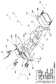
以下、図面を参照しながら実施例2を説明する。図7は他の例となるワイヤハーネスの分岐構造部本体を示す分解斜視図である。また、図8は図7の分岐接続部及び絶縁防水処理部の斜視図、図9及び図10は分岐接続部及び絶縁防水処理部の平面図や斜視図である。
<ワイヤハーネス9及びハーネス本体15について>
ワイヤハーネス9は、ハーネス本体15と、このハーネス本体15の両端にそれぞれ配設されるシールドコネクタ14(図1参照)とを備えて構成される。ハーネス本体15は、二本の導電路16と、この二本の導電路16を覆う筒状編組17、18と、筒状編組17、18の外側に配設される図示しない外装部材と、本発明の特徴部分を含む分岐構造部本体41とを備えて構成される。分岐構造部本体41は、実施例1と同じ位置に配置固定される。
<About the
The
<導電路16について>
図7及び図8において、導電路16は、実施例1と同じであって、導電性の導体16aと、この導体16aを被覆する絶縁性の絶縁体16bとを備えて構成される。
<About the
7 and 8, the
<筒状編組17、18について>
図7において、筒状編組17、18は、実施例1と同じく電磁シールドのための部材であって、細い金属線を編んで筒状に形成される。このような筒状編組17、18の他端は、後述するシールド処理部材43、44、45に接続固定される。尚、筒状編組17、18に替えて金属箔を採用してもよいものとする。
<About
In FIG. 7,
<分岐構造部本体41について>
図7において、分岐構造部本体41は、幹線である導電路16の途中に分岐線22を接続することができるように構成される。分岐線22は、実施例1と同様、エアーコンディショナーを駆動するための補器H(図1参照)の配線として用いられる。分岐構造部本体41は、二本の分岐線22と、分岐接続部23と、絶縁防水処理部42と、筒状編組25と、シールド処理部材43、44、45と、図示しないプロテクタ及びプロテクタカバーとを備えて構成される。
<About the
In FIG. 7, the branch structure part
<分岐線22、分岐接続部23、及び筒状編組25について>
図7及び図8において、分岐線22、分岐接続部23、及び筒状編組25は、実施例1と同じものが採用される。また、同じ状態に形成される。
<About the
7 and 8, the
<絶縁防水処理部42について>
図7ないし図9において、絶縁防水処理部42は、分岐接続部23に対し絶縁処理を施した部分及び防水処理を施した部分になるように形成される。すなわち、絶縁処理及び防水処理の部分として機能するように形成される。本実施例においては、樹脂モールドにて例えば図示形状のように形成される(形状は一例であり、例えば一体化を図ってもよいものとする)。尚、絶縁防水処理部42の形成にあたり(樹脂モールドにあたり)、二本の分岐線22の引き出し角度が適宜設定されるものとする。
<Insulation
7 to 9, the insulating
<シールド処理部材43、44、45について>
図7、図9、及び図10において、シールド処理部材43、44、45は、導電性を有する金属部材であって、それぞれ絶縁防水処理部42を覆い電磁シールド処理を施すことができるように形成される。本実施例のシールド処理部材43、44、45は、所謂シールドシェルであって、略筒状の形状に形成される。
<About the
7, 9, and 10, the
シールド処理部材43、44、45には、フランジ部43a、44a、45aが形成される。また、このフランジ部43a、44a、45aには、ネジ穴43b、44b、45bが形成される。フランジ部43a、44a、45aには、特に図示しないが、防水用のパッキンが設けられる。シールド処理部材43、44、45は、ネジ46の締め付けにより図示形状に組み付けられる。
<ワイヤハーネス9のまとめ及び効果について>
以上、図7ないし図10を参照しながら説明してきたように、本発明に係るワイヤハーネス9は、導電路16を幹線として用い、そして、この幹線である導電路16の途中に分岐線22を接続する構造を有する。具体的には、分岐構造部本体41を有する。この分岐構造部本体41に関し、幹線としての導電路16と分岐線22との接続部分(分岐接続部23)には、絶縁防水処理部42が設けられて絶縁処理及び防水処理が施された状態になることから、高電圧のワイヤハーネス9であっても分岐に関し問題が生じることはない。また、絶縁防水処理部42に関しては、この全部が樹脂モールドにて形成されることから、分岐接続部23が埋まった状態になり、結果、絶縁性や防水性が十分に確保されるのは勿論である。
<Summary of
As described above with reference to FIGS. 7 to 10, the
この他、本発明に係るワイヤハーネス9によれば、シールド処理部材43、44、45を備えることから、絶縁防水処理部42を覆って電磁シールド処理を施すことができる。また、図示しないプロテクタを備えることから、シールド処理部材43、44、45にて覆われた絶縁防水処理部42を収容して外部から保護をすることができる。さらに、図示しないプロテクタを備えることから、分岐の部分があってもワイヤハーネス9の配索をし易くすることができる。
In addition, according to the
従って、実施例2のワイヤハーネス9も実施例1と同じ効果を奏する。すなわち、機器(補器)との接続に関し作業性向上及びコスト低減を図ることができるという効果を奏する。
Therefore, the
この他、本発明は本発明の主旨を変えない範囲で種々変更実施可能なことは勿論である。 In addition, the present invention can of course be modified in various ways within the scope not changing the gist of the present invention.
1…ハイブリッド自動車、 2…エンジン、 3…モータユニット、 4…インバータユニット、 5…バッテリー、 6…エンジンルーム、 7…自動車後部、 8、9…ワイヤハーネス、 10…中間部、 11…車両床下、 12…ジャンクションブロック、 13…ハーネス端末、 14…シールドコネクタ、 15…ハーネス本体、 16…導電路(幹線)、 17、18…筒状編組、 21…分岐構造部本体、 22…分岐線、 23…分岐接続部、 24…絶縁防水処理部、 25…筒状編組、 26…シールド処理部材、 27…プロテクタ、 28…ケース、 29、30…ワイヤーホルダー、 31…樹脂モールド部(樹脂モールド)、 41…分岐構造部本体、 42…絶縁防水処理部、 43、44、45…シールド処理部材、46…ネジ
DESCRIPTION OF
Claims (4)
前記導電路を幹線として用い、且つ、該幹線から分岐するための分岐線を更に備え、前記幹線及び前記分岐線のそれぞれ所定位置の被覆を除去して幹線側導体露出部及び分岐線側導体露出部を形成するとともに、前記幹線側導体露出部及び前記分岐線側導体露出部を接続して分岐接続部を形成し、該分岐接続部に対しては絶縁処理及び防水処理の部分として機能する絶縁防水処理部を設ける
ことを特徴とするワイヤハーネス。 In a wire harness that is electrically connected between high-voltage devices with a conductive path,
The conductive path is used as a trunk line, and a branch line for branching from the trunk line is further provided, and the trunk line conductor exposed portion and the branch line side conductor exposed are removed by removing coverings at predetermined positions of the trunk line and the branch line, respectively. And forming a branch connection part by connecting the trunk line side conductor exposed part and the branch line side conductor exposed part, and insulation functioning as a part of insulation treatment and waterproof treatment for the branch connection part A wire harness characterized by providing a waterproof treatment part.
前記絶縁防水処理部を覆ってシールド処理を施すシールド処理部材を更に備える
ことを特徴とするワイヤハーネス。 The wire harness according to claim 1,
A wire harness further comprising a shield processing member that covers the insulating waterproof processing portion and performs a shield process.
前記シールド処理部材にて覆われた前記絶縁防水処理部を収容するプロテクタを更に備える
ことを特徴とするワイヤハーネス。 The wire harness according to claim 2,
A wire harness, further comprising: a protector that accommodates the insulating waterproofing unit covered with the shield processing member.
前記絶縁防水処理部の一部又は全部を樹脂モールドにより形成する
ことを特徴とするワイヤハーネス。 In the wire harness according to claim 1, 2, or 3,
A wire harness, wherein a part or all of the insulating waterproofing part is formed of a resin mold.
Priority Applications (5)
| Application Number | Priority Date | Filing Date | Title |
|---|---|---|---|
| JP2016056409A JP6468535B2 (en) | 2016-03-22 | 2016-03-22 | Wire harness |
| US15/465,008 US10189422B2 (en) | 2016-03-22 | 2017-03-21 | Wire harness |
| DE102017204809.3A DE102017204809B4 (en) | 2016-03-22 | 2017-03-22 | wiring harness |
| CN201710174520.8A CN107393634B (en) | 2016-03-22 | 2017-03-22 | Harness |
| FR1752374A FR3049383B1 (en) | 2016-03-22 | 2017-03-22 | WIRING HARNESS |
Applications Claiming Priority (1)
| Application Number | Priority Date | Filing Date | Title |
|---|---|---|---|
| JP2016056409A JP6468535B2 (en) | 2016-03-22 | 2016-03-22 | Wire harness |
Publications (2)
| Publication Number | Publication Date |
|---|---|
| JP2017175686A true JP2017175686A (en) | 2017-09-28 |
| JP6468535B2 JP6468535B2 (en) | 2019-02-13 |
Family
ID=59814524
Family Applications (1)
| Application Number | Title | Priority Date | Filing Date |
|---|---|---|---|
| JP2016056409A Active JP6468535B2 (en) | 2016-03-22 | 2016-03-22 | Wire harness |
Country Status (5)
| Country | Link |
|---|---|
| US (1) | US10189422B2 (en) |
| JP (1) | JP6468535B2 (en) |
| CN (1) | CN107393634B (en) |
| DE (1) | DE102017204809B4 (en) |
| FR (1) | FR3049383B1 (en) |
Cited By (4)
| Publication number | Priority date | Publication date | Assignee | Title |
|---|---|---|---|---|
| JP2019187010A (en) * | 2018-04-04 | 2019-10-24 | 矢崎総業株式会社 | Branch circuit body and electric wire branch method |
| JP2019208325A (en) * | 2018-05-30 | 2019-12-05 | 日立金属株式会社 | Branch part holder and wire harness |
| US10886714B2 (en) | 2018-04-04 | 2021-01-05 | Yazaki Corporation | Branching circuit body and branching method of electric wires |
| KR20220009299A (en) * | 2020-07-15 | 2022-01-24 | 주식회사 경신 | High voltage core wire connection device for vehicle |
Families Citing this family (4)
| Publication number | Priority date | Publication date | Assignee | Title |
|---|---|---|---|---|
| CN109243700A (en) * | 2018-09-28 | 2019-01-18 | 南京工业职业技术学院 | prefabricated branch power cable structure for electric power |
| CN109786004B (en) * | 2019-01-17 | 2020-05-15 | 四川兴川泰线缆有限公司 | Graphene pre-branching cable package |
| US11515696B2 (en) * | 2019-12-17 | 2022-11-29 | Te Connectivity Solutions Gmbh | Electrical component enclosure with injected seal and method |
| FR3126557A1 (en) * | 2021-09-01 | 2023-03-03 | Naval Group | CONCENTRATION SYSTEM OF ELECTRICAL SIGNALS BY SEVERAL CONNECTORS AND CABLE GLAND SYSTEM |
Citations (5)
| Publication number | Priority date | Publication date | Assignee | Title |
|---|---|---|---|---|
| JPH02108253U (en) * | 1988-10-07 | 1990-08-28 | ||
| JP2015133822A (en) * | 2014-01-13 | 2015-07-23 | 株式会社オートネットワーク技術研究所 | cable connection structure and cable connection method |
| JP2015139254A (en) * | 2014-01-21 | 2015-07-30 | トヨタ自動車株式会社 | Connection cable |
| JP2016503559A (en) * | 2012-10-31 | 2016-02-04 | デルファイ・テクノロジーズ・インコーポレーテッド | Apparatus and method for splicing shielded wire cables |
| JP2017152229A (en) * | 2016-02-25 | 2017-08-31 | 矢崎総業株式会社 | Wire harness |
Family Cites Families (17)
| Publication number | Priority date | Publication date | Assignee | Title |
|---|---|---|---|---|
| US2956109A (en) * | 1956-08-01 | 1960-10-11 | Burndy Corp | Connection insulating cover |
| US3138657A (en) * | 1962-07-27 | 1964-06-23 | Fargo Mfg Co Inc | Splice insulating system |
| US3715459A (en) * | 1971-07-15 | 1973-02-06 | Amp Inc | Cable coupling covering and moisture barrier |
| US4176245A (en) * | 1978-04-18 | 1979-11-27 | Royston Laboratories, Inc. | Wire splice insulators |
| US4451696A (en) * | 1982-11-15 | 1984-05-29 | Amp Incorporated | Toolless splice sealant device |
| JPH03280365A (en) * | 1990-03-28 | 1991-12-11 | Yazaki Corp | Waterproof seal structure of wire hardness |
| US5594210A (en) * | 1994-09-28 | 1997-01-14 | Yazaki Corporation | Waterproof protective cover |
| JPH09330748A (en) | 1996-06-07 | 1997-12-22 | Yazaki Corp | Wire crimping structure and wire crimping method |
| US7950956B2 (en) * | 2007-04-12 | 2011-05-31 | The Patent Store Llc | Tracer wire connector kits |
| DE102007032892B4 (en) * | 2007-07-14 | 2009-12-24 | Refractory Intellectual Property Gmbh & Co. Kg | Tundish mass and a method for creating a humid Tundishmasse |
| JP5864228B2 (en) * | 2011-11-21 | 2016-02-17 | 矢崎総業株式会社 | High voltage conductive path and wire harness |
| JP5957779B2 (en) | 2011-11-30 | 2016-07-27 | 矢崎総業株式会社 | Wire harness |
| JP5889047B2 (en) * | 2012-03-08 | 2016-03-22 | スリーエム イノベイティブ プロパティズ カンパニー | Insulating waterproof member and insulating waterproof method |
| JP2014022219A (en) | 2012-07-19 | 2014-02-03 | Yazaki Corp | Wire harness |
| JP6329726B2 (en) | 2012-07-25 | 2018-05-23 | 矢崎総業株式会社 | Wire harness exterior member and wire harness |
| US9543747B2 (en) | 2013-10-30 | 2017-01-10 | Delphi Technologies, Inc. | Method for splicing shielded wire cables |
| JP2016163509A (en) * | 2015-03-05 | 2016-09-05 | 住友電装株式会社 | Waterproof structure of wiring harness |
-
2016
- 2016-03-22 JP JP2016056409A patent/JP6468535B2/en active Active
-
2017
- 2017-03-21 US US15/465,008 patent/US10189422B2/en active Active
- 2017-03-22 FR FR1752374A patent/FR3049383B1/en active Active
- 2017-03-22 CN CN201710174520.8A patent/CN107393634B/en active Active
- 2017-03-22 DE DE102017204809.3A patent/DE102017204809B4/en active Active
Patent Citations (5)
| Publication number | Priority date | Publication date | Assignee | Title |
|---|---|---|---|---|
| JPH02108253U (en) * | 1988-10-07 | 1990-08-28 | ||
| JP2016503559A (en) * | 2012-10-31 | 2016-02-04 | デルファイ・テクノロジーズ・インコーポレーテッド | Apparatus and method for splicing shielded wire cables |
| JP2015133822A (en) * | 2014-01-13 | 2015-07-23 | 株式会社オートネットワーク技術研究所 | cable connection structure and cable connection method |
| JP2015139254A (en) * | 2014-01-21 | 2015-07-30 | トヨタ自動車株式会社 | Connection cable |
| JP2017152229A (en) * | 2016-02-25 | 2017-08-31 | 矢崎総業株式会社 | Wire harness |
Cited By (6)
| Publication number | Priority date | Publication date | Assignee | Title |
|---|---|---|---|---|
| JP2019187010A (en) * | 2018-04-04 | 2019-10-24 | 矢崎総業株式会社 | Branch circuit body and electric wire branch method |
| US10886714B2 (en) | 2018-04-04 | 2021-01-05 | Yazaki Corporation | Branching circuit body and branching method of electric wires |
| JP2019208325A (en) * | 2018-05-30 | 2019-12-05 | 日立金属株式会社 | Branch part holder and wire harness |
| JP7059809B2 (en) | 2018-05-30 | 2022-04-26 | 日立金属株式会社 | Branch holder and wire harness |
| KR20220009299A (en) * | 2020-07-15 | 2022-01-24 | 주식회사 경신 | High voltage core wire connection device for vehicle |
| KR102428491B1 (en) * | 2020-07-15 | 2022-08-03 | 주식회사 경신 | High voltage core wire connection device for vehicle |
Also Published As
| Publication number | Publication date |
|---|---|
| FR3049383B1 (en) | 2019-11-01 |
| CN107393634B (en) | 2019-05-31 |
| DE102017204809A1 (en) | 2017-09-28 |
| FR3049383A1 (en) | 2017-09-29 |
| DE102017204809B4 (en) | 2022-03-31 |
| JP6468535B2 (en) | 2019-02-13 |
| CN107393634A (en) | 2017-11-24 |
| US10189422B2 (en) | 2019-01-29 |
| US20170274843A1 (en) | 2017-09-28 |
Similar Documents
| Publication | Publication Date | Title |
|---|---|---|
| JP6468535B2 (en) | Wire harness | |
| JP6301382B2 (en) | Wire harness | |
| JP6527895B2 (en) | Structure of connection between conductive paths and wire harness | |
| JP5884134B2 (en) | Manufacturing method of wire harness | |
| US9469257B2 (en) | Wire harness | |
| US10286857B2 (en) | Wire harness | |
| US9598030B2 (en) | Wire harness having a cover member configured to provide drainage while shielding entry of foreign substances | |
| CN107554445B (en) | Wire harness | |
| JP2016032388A (en) | Wiring harness | |
| JP2017022897A (en) | Exterior member and wiring harness | |
| JP2014192906A (en) | Wire harness | |
| JP6685497B2 (en) | Wire harness | |
| JP6045618B2 (en) | Exterior member and wire harness | |
| US9601911B2 (en) | Wire harness | |
| US10030794B2 (en) | Corrugated tube and wire harness | |
| JP6594128B2 (en) | Wire harness | |
| US20220055550A1 (en) | Wire harness | |
| JP2016136458A (en) | Terminal fitting, wiring harness, and manufacturing method of terminal fitting | |
| JP6210971B2 (en) | Water stop structure and wire harness | |
| JP6594127B2 (en) | Wire harness | |
| JP2017139918A (en) | Wire harness | |
| JP6211036B2 (en) | Exterior member and wire harness | |
| JP2020108186A (en) | Wire harness | |
| JP2016119270A (en) | Cutoff structure, cutoff method and wire harness |
Legal Events
| Date | Code | Title | Description |
|---|---|---|---|
| A977 | Report on retrieval |
Free format text: JAPANESE INTERMEDIATE CODE: A971007 Effective date: 20180807 |
|
| A131 | Notification of reasons for refusal |
Free format text: JAPANESE INTERMEDIATE CODE: A131 Effective date: 20180821 |
|
| A521 | Request for written amendment filed |
Free format text: JAPANESE INTERMEDIATE CODE: A523 Effective date: 20181004 |
|
| A131 | Notification of reasons for refusal |
Free format text: JAPANESE INTERMEDIATE CODE: A131 Effective date: 20181106 |
|
| A521 | Request for written amendment filed |
Free format text: JAPANESE INTERMEDIATE CODE: A523 Effective date: 20181213 |
|
| TRDD | Decision of grant or rejection written | ||
| A01 | Written decision to grant a patent or to grant a registration (utility model) |
Free format text: JAPANESE INTERMEDIATE CODE: A01 Effective date: 20181225 |
|
| A61 | First payment of annual fees (during grant procedure) |
Free format text: JAPANESE INTERMEDIATE CODE: A61 Effective date: 20190108 |
|
| R150 | Certificate of patent or registration of utility model |
Ref document number: 6468535 Country of ref document: JP Free format text: JAPANESE INTERMEDIATE CODE: R150 |
|
| R250 | Receipt of annual fees |
Free format text: JAPANESE INTERMEDIATE CODE: R250 |
|
| R250 | Receipt of annual fees |
Free format text: JAPANESE INTERMEDIATE CODE: R250 |
|
| S531 | Written request for registration of change of domicile |
Free format text: JAPANESE INTERMEDIATE CODE: R313531 |
|
| R350 | Written notification of registration of transfer |
Free format text: JAPANESE INTERMEDIATE CODE: R350 |
|
| R250 | Receipt of annual fees |
Free format text: JAPANESE INTERMEDIATE CODE: R250 |