JP2017174680A - LED lamp and LED lighting device - Google Patents
LED lamp and LED lighting device Download PDFInfo
- Publication number
- JP2017174680A JP2017174680A JP2016060400A JP2016060400A JP2017174680A JP 2017174680 A JP2017174680 A JP 2017174680A JP 2016060400 A JP2016060400 A JP 2016060400A JP 2016060400 A JP2016060400 A JP 2016060400A JP 2017174680 A JP2017174680 A JP 2017174680A
- Authority
- JP
- Japan
- Prior art keywords
- led
- reverse
- voltage
- led lamp
- led array
- Prior art date
- Legal status (The legal status is an assumption and is not a legal conclusion. Google has not performed a legal analysis and makes no representation as to the accuracy of the status listed.)
- Pending
Links
Images


Abstract
Description
本発明は、LEDランプ及びそれを用いたLED照明装置に関する。 The present invention relates to an LED lamp and an LED lighting device using the same.
LEDランプは、一般に定電流制御機能を有する直流電源装置から給電される。しかし、直流電源装置の極性とLEDランプの極性が誤って接続された場合、出力電流が遮断されることから直流電源装置はその定電流制御機能によって無負荷電圧(開放電圧)を出力し続けることになる。この場合、LEDランプを構成するLEDアレイには、その無負荷電圧が逆方向電圧として印加される。LEDの逆耐圧は一般に5V程度であり、直流電源装置からの無負荷電圧(数十〜数百V)が印加されるとLEDアレイは故障し得る。ここで、LEDアレイの入力側にダイオードブリッジが接続される構成(例えば、特許文献1参照)では、上記のような誤接続の場合であっても、供給される電圧がダイオードブリッジによって全波整流されるので、LEDアレイに逆方向電圧は印加されない。したがって、この構成は、LEDランプと直流電源装置の間の誤接続対策の一手段となり得る。 The LED lamp is generally supplied with power from a DC power supply device having a constant current control function. However, if the polarity of the DC power supply device and the polarity of the LED lamp are mistakenly connected, the output current will be cut off, so the DC power supply device will continue to output no-load voltage (open voltage) by its constant current control function. become. In this case, the no-load voltage is applied as a reverse voltage to the LED array constituting the LED lamp. The reverse withstand voltage of the LED is generally about 5V, and the LED array can fail when a no-load voltage (several tens to several hundreds V) is applied from the DC power supply device. Here, in a configuration in which a diode bridge is connected to the input side of the LED array (see, for example, Patent Document 1), even if the connection is incorrect as described above, the supplied voltage is full-wave rectified by the diode bridge. Therefore, no reverse voltage is applied to the LED array. Therefore, this configuration can be a means for preventing erroneous connection between the LED lamp and the DC power supply device.
しかし、上記のようにLEDアレイの前段にダイオードブリッジを接続する構成では、通常点灯時において、LED電流が常に2個のダイオードを通過することになる。したがって、LEDランプと直流電源装置の間の誤接続の対策のために、通常点灯時に不要な損失が発生してしまうことが問題となる。 However, in the configuration in which the diode bridge is connected to the front stage of the LED array as described above, the LED current always passes through the two diodes during normal lighting. Therefore, there is a problem that unnecessary loss occurs during normal lighting in order to prevent erroneous connection between the LED lamp and the DC power supply device.
そこで、本発明は、直流電源装置がLEDランプに対して逆極性で誤接続された場合でもLEDアレイを保護することができ、かつ通常点灯時に追加の損失をもたらさないLEDランプ及びそれを用いたLED照明装置を提供することを課題とする。 Therefore, the present invention can protect an LED array even when the DC power supply device is erroneously connected to the LED lamp with a reverse polarity, and uses the LED lamp that does not cause an additional loss during normal lighting. It is an object to provide an LED lighting device.
本発明のLEDランプは、直列接続された複数のLEDを有するLEDアレイと、LEDアレイに並列接続され、LEDアレイに順方向電圧が印加される場合に非導通となり、LEDアレイに逆方向電圧が印加される場合に導通し、かつ導通時にLEDアレイに印加される逆方向電圧が複数のLEDの各々の逆耐圧未満となるような電圧降下を有するバイパス回路とを備える。 The LED lamp of the present invention has an LED array having a plurality of LEDs connected in series, and is connected in parallel to the LED array and becomes non-conductive when a forward voltage is applied to the LED array, and a reverse voltage is applied to the LED array. And a bypass circuit having a voltage drop that conducts when applied, and has a reverse voltage applied to the LED array when conducting, which is less than the reverse withstand voltage of each of the plurality of LEDs.
上記LEDランプによると、LEDランプが直流電源装置に対して逆極性で誤接続された場合に、LEDアレイに並列接続されたバイパス回路が導通する。この時のバイパス回路の電圧降下が各LEDの逆耐圧未満であるので、LEDアレイが逆方向電圧から保護される。また、通常点灯時には、バイパス回路は非導通となるのでバイパス回路での損失は発生しない。したがって、直流電源装置がLEDランプに対して逆極性で誤接続された場合でもLEDアレイを保護することができ、かつ通常点灯時に追加の損失をもたらさないLEDランプが実現される。 According to the LED lamp, when the LED lamp is erroneously connected to the DC power supply device with the reverse polarity, the bypass circuit connected in parallel to the LED array becomes conductive. Since the voltage drop of the bypass circuit at this time is less than the reverse breakdown voltage of each LED, the LED array is protected from the reverse voltage. Further, during normal lighting, since the bypass circuit is non-conductive, no loss occurs in the bypass circuit. Therefore, even when the DC power supply device is erroneously connected to the LED lamp with a reverse polarity, the LED array can be protected, and an LED lamp that does not cause an additional loss during normal lighting is realized.
第1の形態では、パイパス回路は、LEDアレイに逆並列接続された整流ダイオードからなる。通常、整流ダイオードの電圧降下すなわち順方向電圧はLEDの逆耐圧よりも低いため、整流ダイオードは上記バイパス回路として好適である。これにより、簡素かつ安価な構成で上記効果を奏するLEDランプが実現される。 In the first form, the bypass circuit is composed of a rectifier diode connected in antiparallel to the LED array. Usually, since the voltage drop of the rectifier diode, that is, the forward voltage, is lower than the reverse breakdown voltage of the LED, the rectifier diode is suitable as the bypass circuit. Thereby, the LED lamp which has the said effect with a simple and cheap structure is implement | achieved.
第2の形態では、複数のLEDが、アノード端からカソード端に向けて、直列接続された第1、第2及び第3のLED部分からなり、パイパス回路は、第2及び第3のLED部分の直列回路に逆並列接続された第1の整流ダイオードと、第1及び第2のLED部分の直列回路に逆並列接続された第2の整流ダイオードとを含む。これにより、LEDランプが直流電源装置に対して逆極性で誤接続された場合に、第1の整流ダイオード、第2のLED部分及び第2の整流ダイオードに電流が流れ、第2のLED部分を発光させることができる。この発光により、LEDランプと直流電源装置の間の誤接続をユーザに警告することができる。 In the second embodiment, the plurality of LEDs are composed of first, second, and third LED portions connected in series from the anode end to the cathode end, and the bypass circuit includes the second and third LED portions. And a second rectifier diode connected in antiparallel to the series circuit of the first and second LED portions. As a result, when the LED lamp is erroneously connected to the DC power supply device with the reverse polarity, a current flows through the first rectifier diode, the second LED portion, and the second rectifier diode, and the second LED portion is Can emit light. This light emission can warn the user of an erroneous connection between the LED lamp and the DC power supply.
第3の形態では、バイパス回路は、複数のLEDのうちの少なくとも1つの選択LEDの各々に逆並列接続された警告用LEDと、複数のLEDのうちの残余のLEDの直列回路に逆並列接続された整流ダイオードとを含む。これにより、LEDランプが直流電源装置に対して逆極性で誤接続された場合に、警告用LED及び整流ダイオードに電流が流れ、警告用LEDを発光させることができる。この発光により、LEDランプと直流電源装置の間の誤接続をユーザに警告することができる。 In the third mode, the bypass circuit is connected in reverse parallel to the series circuit of the warning LED connected in reverse parallel to each of at least one selected LED of the plurality of LEDs and the remaining LED of the plurality of LEDs. Rectified diodes. As a result, when the LED lamp is erroneously connected to the DC power supply device with the reverse polarity, current flows through the warning LED and the rectifier diode, and the warning LED can be caused to emit light. This light emission can warn the user of an erroneous connection between the LED lamp and the DC power supply.
ここで、警告用LEDは、選択LED及び残余のLEDとは異なる発光色を有していてもよい。これにより、ユーザは誤接続をより明確に認識することができる。 Here, the warning LED may have a light emission color different from that of the selection LED and the remaining LEDs. Thereby, the user can recognize an incorrect connection more clearly.
さらに、上記第1から第3の形態において、LEDアレイ及びバイパス回路の並列回路に対して直列接続された電流ヒューズが設けられることが望ましい。これにより、LEDランプが交流電源に誤接続された場合又はバッテリに逆極性で誤接続された場合であっても、電流ヒューズの溶断により、LEDランプが過電流から保護される。したがって、種々の誤接続からLEDランプを保護することが可能となる。 Furthermore, in the first to third embodiments, it is desirable to provide a current fuse connected in series to the parallel circuit of the LED array and the bypass circuit. As a result, even when the LED lamp is erroneously connected to the AC power source or when it is erroneously connected to the battery with the reverse polarity, the LED lamp is protected from overcurrent by melting the current fuse. Therefore, it becomes possible to protect the LED lamp from various misconnections.
本発明のLED照明装置は、上記いずれかのLEDランプと、LEDランプに定電流を供給する直流電源装置とを備える。上記のように誤接続があったとしてもLEDランプが保護されるので、LEDランプと直流電源装置との接続構成(端子、コネクタ等)を、誤装着防止用の特殊な構成とする必要がなく、安価なLED照明装置が実現される。 The LED lighting device of the present invention includes any one of the above LED lamps and a DC power supply device that supplies a constant current to the LED lamps. Even if there is an incorrect connection as described above, the LED lamp is protected, so there is no need for the connection configuration (terminal, connector, etc.) between the LED lamp and the DC power supply device to be a special configuration for preventing erroneous mounting. An inexpensive LED lighting device is realized.
<第1の実施形態>
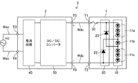
図1に、第1の実施形態によるLEDランプ1及びそれを用いたLED照明装置3を示す。LED照明装置3は、LEDランプ1及び直流電源装置2を備える。LEDランプ1の端子T1及びT2は、直流配線Wdcを介して出力端子T5及びT6に接続され、直流電源装置2の入力端子T3及びT4は交流配線Wacを介して交流電源ACに接続される。なお、直流配線Wdcは、LEDランプ1に属する配線であってもよいし、直流電源装置2に属する配線であってもよい。あるいは、直流配線Wdcは、LEDランプ1に属する配線と直流電源装置2に属する配線がコネクタを介して接続される形態で構成されてもよい。
<First Embodiment>
FIG. 1 shows an
直流電源装置2は、整流回路40及びDC/DCコンバータ50を有する。整流回路40はダイオードブリッジ等からなり、交流配線Wacから供給される交流電圧を全波整流する。DC/DCコンバータ50は、例えば、フライバックコンバータ、又は昇圧チョッパ回路及び降圧チョッパ回路の組合せといったようなスイッチング電源回路を含み、整流回路40の整流出力を所定の直流出力に変換し、これをLEDランプ1に直流配線Wdcを介して供給する。本実施形態では、出力端子T5及びT6がそれぞれ正極(+)及び負極(−)となる。
The DC
DC/DCコンバータ50は、そのスイッチング電源回路を構成するスイッチング素子のPWM制御によって一定の直流電流を出力する定電流制御機能を有し、LEDランプ1に対して定電流を供給することができる。例えば、DC/DCコンバータ50では、LEDランプ1への出力電流が検出され、検出された出力電流値と目標電流値とが一致するように、スイッチング素子のPWM制御のオン時間又はオンデューティが決定されるように構成される。
The DC /
LEDランプ1は、端子T1と端子T2の間に、LEDアレイ10、バイパス回路20及び電流ヒューズ30を備える。LEDアレイ10は、直列接続された複数のLED11を有し、アノード端が端子T1側に接続され、カソード端が端子T2側に接続される。バイパス回路20は、本実施形態では、LEDアレイ10に逆並列接続された整流ダイオード21からなる。すなわち、整流ダイオード21のアノード及びカソードが、LEDアレイ10のカソード端及びアノード端にそれぞれ接続される。電流ヒューズ30は、LEDアレイ10及びバイパス回路20の並列回路に対して直列に挿入接続される。
The
なお、本開示において、ダイオードを発光ダイオードとそれ以外のダイオードに文言上区別するため、前者をLEDといい、後者を整流ダイオードというものとする。各実施形態において、説明の目的上、LEDの順方向電圧(Vf)は2〜3V程度であり、逆耐圧は5V程度であるものとする(一般には、逆耐圧は5〜10V程度である)。また、各実施形態において、説明の目的上、整流ダイオードの逆耐圧は直流電源装置2の最大出力電圧を超える充分に高いものであり、順方向電圧(Vf)は1V程度であるものとする(一般には、順方向電圧は0.5〜1V程度である)。また、本開示において、LEDランプ1又はLEDアレイ10の保護とは、LEDランプ1又はLEDアレイ10の故障を回避することだけでなく、LEDランプ1又はLEDアレイ10が故障してしまった場合にその後の二次的な故障(延焼等)を防止することも含むものである。
In the present disclosure, the former is referred to as an LED, and the latter is referred to as a rectifier diode, in order to distinguish the diode into a light emitting diode and another diode. In each embodiment, for the purpose of explanation, the forward voltage (Vf) of the LED is about 2 to 3 V, and the reverse breakdown voltage is about 5 V (generally, the reverse breakdown voltage is about 5 to 10 V). . In each embodiment, for the purpose of explanation, it is assumed that the reverse breakdown voltage of the rectifier diode is sufficiently higher than the maximum output voltage of the DC
出力端子T5及びT6がそれぞれ端子T1及びT2に正しく接続されている場合(以下、「通常点灯時」という)、直流電源装置2からの直流電流は、端子T1→電流ヒューズ30→LEDアレイ10→端子T2に流れる。通常点灯時には、整流ダイオード21は非導通となる。
When the output terminals T5 and T6 are correctly connected to the terminals T1 and T2 respectively (hereinafter referred to as “normally lit”), the direct current from the direct current
一方、出力端子T5及びT6がそれぞれ端子T2及びT1に誤って接続された場合(以下、「DC誤接続」という)、直流電源装置2からの直流電流は、端子T2→整流ダイオード21→電流ヒューズ30→端子T1に流れる。ここで、整流ダイオード21の電圧降下(順方向電圧)は1V程度であるので、LEDアレイ10には、逆方向電圧としてこの電圧降下以下の電圧しか印加されない。直列接続された複数のLED11の各々にかかる逆方向電圧(Vr)はLEDアレイ10の両端にかかる逆方向電圧の等分とはならないが、LEDアレイ10の両端にかかる逆方向電圧が各LED11の逆耐圧以下であれば、各LED11は確実に保護されることになる。本実施形態によると、各LED11に印加され得る逆方向電圧(1V程度)は逆耐圧(5V程度)未満であるので、各LED11は保護される。
On the other hand, when the output terminals T5 and T6 are erroneously connected to the terminals T2 and T1, respectively (hereinafter referred to as “DC misconnection”), the direct current from the direct current
DC誤接続の場合に、直流電源装置2の出力が定電流制御されていれば、過大な電流が整流ダイオード21に流れることもない。言い換えると、整流ダイオード21には、LEDアレイ10のLED電流相当の電流容量を有するダイオードが採用される。DC誤接続の場合には、直流電源装置2の出力電圧は整流ダイオード21の順方向電圧(1V程度)まで低下するので、DC/DCコンバータ50においては軽負荷状態となる。したがって、DC/DCコンバータ50の定電流制御に伴う出力動作(最小PWMオン時間でのスイッチング動作)は間欠的なものとなり得る。なお、DC誤接続の場合に、上記定電流制御が行われていれば、電流ヒューズ30は溶断しない。
In the case of DC misconnection, if the output of the DC
また、交流電源ACが端子T1及びT2に誤接続された場合(以下、「AC誤接続」という)、端子T1が端子T2に対して高電位となる期間にはLEDアレイ10に電流が流れ、端子T2が端子T1に対して高電位となる期間には整流ダイオード21に電流が流れる。特に、整流ダイオード21に電流が流れる状態においては、交流電源ACが実質的に短絡されることにより発生する過大な電流によって、電流ヒューズ30が溶断する。
Further, when the AC power supply AC is erroneously connected to the terminals T1 and T2 (hereinafter referred to as “AC erroneous connection”), a current flows through the
また、端子T1及びT2が、バッテリ等の定電流制御されない直流電源(不図示)に誤って接続された場合(以下、「バッテリ誤接続」という)を想定する。例えば、バッテリ電圧が12Vであり、LEDアレイ10の合計順方向電圧が12Vより高いものとする。バッテリの正極及び負極がそれぞれ端子T1及びT2に接続された場合(以下、「バッテリ順極性誤接続」という)、LEDアレイ10及び整流ダイオード21とも非導通となるので、問題は起こらない。
Further, it is assumed that the terminals T1 and T2 are erroneously connected to a DC power source (not shown) such as a battery that is not controlled with constant current (hereinafter referred to as “battery misconnection”). For example, it is assumed that the battery voltage is 12V and the total forward voltage of the
一方、バッテリの正極及び負極がそれぞれ端子T2及びT1に接続された場合(以下、「バッテリ逆極性誤接続」という)、バッテリが整流ダイオード21を介して実質的に短絡された状態となるので、過大な電流が発生し、電流ヒューズ30が溶断する。また、DC誤接続の場合と同様に、LEDアレイ10にかかる逆方向電圧は、各LED11の逆耐圧未満の1V程度となるので、LEDアレイ10は逆方向電圧から保護される。なお、DC/DCコンバータ50が定電流制御ではなく定電圧制御を実行する場合の動作も、バッテリ逆極性誤接続の場合と実質的に同じである(すなわち、電流ヒューズ30が溶断する)。
On the other hand, when the positive and negative electrodes of the battery are connected to the terminals T2 and T1, respectively (hereinafter referred to as “battery reverse polarity misconnection”), the battery is substantially short-circuited via the
このように、LEDアレイ10及びバイパス回路20に直列接続された電流ヒューズ30が設けられるので、AC誤接続の場合又はバッテリ逆極性誤接続の場合に、LEDアレイ10及びバイパス回路20を過電流から保護することができる。したがって、バイパス回路20に加えて電流ヒューズ30を設けることによって、あらゆる誤接続に対するLEDランプ1の保護が可能となる。この場合、後に電流ヒューズ30を交換すればLEDランプ1は再使用可能である。
Thus, since the
以上のように、本実施形態のLEDランプ1は、直列接続された複数のLED11を有するLEDアレイ10と、LEDアレイ10に並列接続されたバイパス回路20を備え、バイパス回路20は、LEDアレイ10に逆並列接続された整流ダイオード21からなる。整流ダイオード21は、LEDアレイ10に順方向電圧が印加される場合に非導通となり、LEDアレイ10に逆方向電圧が印加される場合に導通し、導通時にLEDアレイ10に印加される逆方向電圧が各LED11の逆耐圧未満となるような電圧降下(順方向電圧)を有する。これにより、DC誤接続の場合、LEDアレイ10に逆並列接続された整流ダイオード21が導通するとともに、LEDアレイ10に印加される整流ダイオード21の順方向電圧は各LED11の逆耐圧未満となるので、LEDアレイ10が逆方向電圧から保護される。また、通常点灯時には、整流ダイオード21は非導通となるのでバイパス回路20での損失は発生しない。したがって、DC誤接続の場合にLEDアレイ10を保護することができ、かつ通常点灯時に追加の損失をもたらさないLEDランプ1が実現される。
As described above, the
特に、本実施形態では、上述したように、パイパス回路20が整流ダイオード21からなるので、簡素かつ安価な構成で上記の効果を奏するLEDランプ1が実現される。
In particular, in the present embodiment, as described above, the
また、本実施形態のLED照明装置3は、LEDランプ1と、LEDランプ1に定電流を供給する直流電源装置2を備える。上記のように各種誤接続があったとしてもLEDランプ1が保護されるので、LEDランプ1及び直流電源装置2の接続構成(端子、コネクタ等)を、誤装着防止用の特殊な構成とする必要がなく、安価なLED照明装置3が実現される。
The LED lighting device 3 of the present embodiment includes an
<第2の実施形態>
上記第1の実施形態では、DC誤接続の場合にLEDランプ1の全体が不点灯となる構成を示したが、本実施形態では、DC誤接続の場合にLEDランプ1の一部が警告用に点灯する構成を示す。本実施形態において、第1の実施形態と同様の構成には同様の符号を付し、重複する説明を省略する。
<Second Embodiment>
In the first embodiment, the configuration in which the
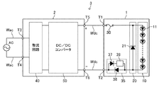
図2に、本実施形態によるLEDランプ1及びそれを用いたLED照明装置3を示す。本実施形態では、LEDアレイ10の複数のLED11は、アノード端からカソード端に向けて、直列接続された第1のLED部分11a、第2のLED部分11b及び第3のLED部分11cに区分けされる。ただし、各LED部分を構成するLED11の各々は同じものである。第2のLED部分11bは1つのLED11(以下、「LED11b」ともいう)からなり、第1のLED部分11a及び第3のLED部分11cは残余のLED11を含む。図2においては、3個のLED11が第1のLED部分11a及び第3のLED部分11cの各々に含まれる構成を示すが、LED11の接続数はこれに限定されない。
FIG. 2 shows an
パイパス回路20は、整流ダイオード22及び23を備える。整流ダイオード22はLED11b及び第3のLED部分11cの直列回路に逆並列接続され、整流ダイオード23は第1のLED部分11a及びLED11bの直列回路に逆並列接続される。したがって、LED11bがバイパス回路20の一部を構成しているともいえる。
The
通常点灯時には、直流電源装置2からの直流電流は、端子T1→電流ヒューズ30→第1のLED部分11a→LED11b→第3のLED部分10c→端子T2に流れる。したがって、通常点灯時には、LEDアレイ10が点灯し、整流ダイオード22及び23は非導通となる。
During normal lighting, the DC current from the
DC誤接続の場合には、直流電源装置2からの直流電流は、端子T2→整流ダイオード22→LED11b→整流ダイオード23→電流ヒューズ30→端子T1に流れる。したがって、DC誤接続の場合にはLED11bのみが発光する。
In the case of DC misconnection, the direct current from the direct current
DC誤接続の場合において、整流ダイオード22の順方向電圧は1V程度であり、LED11bの順方向電圧は2〜3V程度であるので、第3のLED部分11cに印加される逆方向電圧は3〜4V程度となる。同様に、整流ダイオード23の順方向電圧は1V程度であり、LED11bの順方向電圧は2〜3V程度であるので、第1のLED部分11aに印加される逆方向電圧は3〜4V程度となる。これらの逆方向電圧は、第3のLED部分11c及び第1のLED部分11aの各LED11の逆耐圧(5V程度)よりも若干低いため、第3のLED部分11c及び第1のLED部分11aは逆方向電圧から保護される。
In the case of DC misconnection, the forward voltage of the
また、DC誤接続の場合に、直流電源装置2の出力が定電流制御されていれば、過大な電流が整流ダイオード22及び23並びにLED11bに流れることはなく、電流ヒューズ30は溶断しない。DC誤接続の場合には、直流電源装置2の出力電圧は整流ダイオード22及び23並びにLED11bの合計順方向電圧(4〜5V程度)まで低下するので、DC/DCコンバータ50においては軽負荷状態となる。したがって、DC/DCコンバータ50の定電流制御に伴う出力動作(最小PWMオン時間でのスイッチング動作)は間欠的なものとなり得る。
Further, in the case of DC misconnection, if the output of the DC
AC誤接続の場合及びバッテリ誤接続の場合の各動作は、第1の実施形態で説明したものと実質的に同じである。すなわち、バッテリ順極性誤接続の場合にはLEDランプ1に電流は流れず、AC誤接続又はバッテリ逆極性誤接続の場合には電流ヒューズ30の溶断によりLEDランプ1が保護される。また、DC/DCコンバータ50が定電流制御ではなく定電圧制御を実行する場合の動作は、バッテリ逆極性誤接続の場合と実質的に同じとなる(すなわち、電流ヒューズ30が溶断する)。
The operations in the case of AC misconnection and battery misconnection are substantially the same as those described in the first embodiment. In other words, no current flows through the
以上のように、本実施形態では、LEDアレイ10が、アノード端からカソード端に向けて、直列接続された第1、第2及び第3のLED部分11a、11b及び11cからなり、パイパス回路20が、第2のLED部分11b及び第3のLED部分11cの直列回路に逆並列接続された整流ダイオード22と、第1のLED部分11a及び第2のLED部分11bの直列回路に逆並列接続された整流ダイオード23からなる。これにより、DC誤接続の場合に、整流ダイオード22及び23並びに第2のLED部分11bが導通し、第1のLED部分11a及び第3のLED部分11cに印加される逆方向電圧が各LED11の逆耐圧未満となるので、LEDアレイ10が逆方向電圧から保護される。また、通常点灯時には、整流ダイオード22及び23は非導通となるのでこれらによる損失は発生しない。したがって、第1の実施形態と同様に、DC誤接続の場合にLEDアレイ10を保護することができ、かつ通常点灯時に追加の損失をもたらさないLEDランプ1が実現される。
As described above, in the present embodiment, the
特に本実施形態では、DC誤接続の場合に、整流ダイオード22、第2のLED部分11b及び整流ダイオード23に電流が流れ、第2のLED部分11bを発光させることができる。この発光により、DC誤接続をユーザに警告することができる。
In particular, in the present embodiment, in the case of DC misconnection, current flows through the
<第3の実施形態>
上記第2の実施形態では、LEDアレイ10の一部を構成するLED11が警告用のLEDを兼ねる構成を示したが、本実施形態では、LEDアレイ10とは別のLEDが警告用に設けられる構成を示す。本実施形態において、第1及び第2の実施形態と同様の構成には同様の符号を付し、重複する説明を省略する。
<Third Embodiment>
In the second embodiment, the
図3に、本実施形態によるLEDランプ1及びそれを用いたLED照明装置3を示す。本実施形態では、LEDアレイ10の複数のLED11は、選択LED11s及び残余のLED11rに分けられる。バイパス回路20は、整流ダイオード24及び警告用LED25を備える。各警告用LED25は各選択LED11sに逆並列接続され、整流ダイオード24は残余のLED11rの直列回路に逆並列接続される。
FIG. 3 shows the
通常点灯時には、直流電源装置2からの直流電流は、端子T1→電流ヒューズ30→LED11s→LED11r→端子T2に流れる。したがって、通常点灯時には、整流ダイオード24及び警告用LED25は非導通(非発光)となる。
At the time of normal lighting, the direct current from the direct current
DC誤接続の場合には、直流電源装置2からの直流電流は、端子T2→整流ダイオード24→警告用LED25→電流ヒューズ30→端子T1に流れる。したがって、DC誤接続の場合には警告用LED25が発光する。
In the case of DC misconnection, the direct current from the direct current
ここで、整流ダイオード24の順方向電圧(1V程度)は各LED11の逆耐圧(5V程度)より低いので、残余のLED11rは逆方向電圧から保護される。また、各警告用LED25の順方向電圧(2〜3V程度)が各LED11sの逆耐圧(5V程度)未満となり、かつ各選択LED11sの順方向電圧(2〜3V程度)が各警告用LED25の逆耐圧(5V程度)未満となるので、選択LED11s及び警告用LED25の双方が逆方向電圧から保護される。
Here, since the forward voltage (about 1V) of the
また、DC誤接続の場合に、直流電源装置2の出力が定電流制御されていれば、過大な電流が整流ダイオード24及び警告用LED25に流れることはなく、電流ヒューズ30は溶断しない。DC誤接続の場合には、直流電源装置2の出力電圧は整流ダイオード24及び警告用LED25の合計順方向電圧(5〜7V程度)まで低下するので、DC/DCコンバータ50においては軽負荷状態となる。したがって、DC/DCコンバータ50の定電流制御に伴う出力動作(最小PWMオン時間でのスイッチング動作)は間欠的なものとなり得る。
Further, in the case of DC misconnection, if the output of the DC
AC誤接続の場合及びバッテリ誤接続の場合の各動作は、第1の実施形態で説明したものと実質的に同じである。すなわち、バッテリ順極性誤接続の場合にはLEDランプ1に電流は流れず、AC誤接続又はバッテリ逆極性誤接続の場合には電流ヒューズ30の溶断によりLEDランプ1が保護される。また、DC/DCコンバータ50が定電流制御ではなく定電圧制御を実行する場合の動作は、バッテリ逆極性誤接続の場合と実質的に同じとなる(すなわち、電流ヒューズ30が溶断する)。
The operations in the case of AC misconnection and battery misconnection are substantially the same as those described in the first embodiment. In other words, no current flows through the
なお、図3に示す例では、2対の選択LED11s及び警告用LED25が設けられる構成を示すが、1対又は3対以上の選択LED11s及び警告用LED25が設けられてもよい。選択LED11s及び警告用LED25の対が2以上の場合には、残余のLED11rに逆並列接続される整流ダイオード24を1つとするために、複数の警告用LED25がLEDアレイ10のアノード端側及びカソード端側の一方又は両方にまとめて配置されることが望ましい。
3 shows a configuration in which two pairs of
また、各LED11の順方向電圧及び逆耐圧並びに警告用LED25の順方向電圧及び逆耐圧が所定の条件を満たす場合(例えば、各LED11の順方向電圧が比較的低く、警告用LED25の逆耐圧が比較的高い場合)には、複数の選択LED11sに対して1つの警告用LED25が逆並列接続されてもよい。
Further, when the forward voltage and reverse withstand voltage of each
以上のように、本実施形態では、バイパス回路20は、選択LED11sの各々に逆並列接続された警告用LED25、及び残余のLED11rの直列回路に逆並列接続された整流ダイオード24からなる。これにより、DC誤接続の場合に、整流ダイオード24及び警告用LED25が導通し、LEDアレイ10に印加される逆方向電圧が各LED11の逆耐圧未満となるので、LEDアレイ10が逆方向電圧から保護される。また、通常点灯時には、整流ダイオード24及び警告用LED25は非導通となるので、これらの素子による損失は発生しない。したがって、第1の実施形態と同様に、DC誤接続の場合にLEDアレイ10を保護することができ、かつ通常点灯時に追加の損失をもたらさないLEDランプ1が実現される。
As described above, in the present embodiment, the
特に本実施形態では、DC誤接続の場合に、整流ダイオード24及び警告用LED25に電流が流れ、警告用LED25を発光させることができる。この発光により、DC誤接続をユーザに警告することができる。また、警告用LED25はLED11(選択LED11s及び残余のLED11r)とは異なる特性(発光色、順電圧−順電流特性、逆耐圧等)を有するものであってもよい。例えば、警告用LED25がLED11とは異なる発光色を有していれば、ユーザはDC誤接続をより明確に認識することができる。
In particular, in the present embodiment, in the case of incorrect DC connection, current flows through the
<変形例>
以上に本発明の好適な実施形態を示したが、本発明は、例えば以下に示すように種々の態様に変形可能である。
<Modification>
Although preferred embodiments of the present invention have been described above, the present invention can be modified into various modes as shown below, for example.
(1)直流配線Wdcの省略
上記各実施形態では、LEDランプ1と直流電源装置2が直流配線Wdcを介して接続される別置型構成を示したが、本発明はLEDランプ1と直流電源装置2が配線を介さずに装着及び接続される一体型構成にも適用可能である。すなわち、通常点灯時に端子T1及びT2が出力端子T5及びT6に直接接続されてもよい(DC誤接続の場合には端子T1及びT2が出力端子T6及びT5に直接接続される)。この場合、AC誤接続及びバッテリ誤接続は想定されないため、DC/DCコンバータ50が定電流制御機能を有することを条件として電流ヒューズ30は省略されてもよい。
(1) Omission of DC wiring Wdc In each of the above embodiments, the
(2)電流制限回路の挿入
上記各実施形態では、バッテリ逆極性誤接続の場合に電流ヒューズ30が溶断する構成を示したが、この場合にも電流ヒューズ30を溶断させない構成も可能である。例えば、図4に示すように、LEDランプ1が、LEDアレイ10及びバイパス回路20の並列回路に対して直列接続された電流制限回路35を備えるようにしてもよい。電流制限回路35は、端子T1から端子T2に向かう方向を順方向とする整流ダイオード36と、端子T2から端子T1に向かう方向を順方向とする整流ダイオード37と、整流ダイオード37に直列接続されたインピーダンス素子38を備える。すなわち、整流ダイオード37とインピーダンス素子38の直列回路が整流ダイオード36に逆並列接続される。インピーダンス素子38は、抵抗、PTCサーミスタ等からなる。
(2) Insertion of Current Limiting Circuit In each of the above-described embodiments, the configuration in which the
なお、図4では、第1の実施形態との関連でバイパス回路20が整流ダイオード21からなる構成が図示されているが、本変形例は上記第2又は第3の実施形態の構成とも組み合わせることができる。ただし、いずれの場合であっても、通常点灯時にLED電流が1つの整流ダイオード36を通過するので、若干の追加の損失が発生する。
In FIG. 4, a configuration in which the
バッテリ逆極性誤接続の場合に、直流電源装置2からの直流電流は、端子T2→整流ダイオード37→インピーダンス素子38→バイパス回路20(整流ダイオード21)→電流ヒューズ30→端子T1に流れる。この場合、インピーダンス素子38において電流が制限されるので、電流ヒューズ30は溶断しない。なお、バッテリ順極性誤接続の場合の動作は上記各実施形態と同様であり、LEDランプ1に電流は発生しない。
In the case of battery reverse polarity erroneous connection, the DC current from the
DC誤接続の場合、電流経路はバッテリ逆極性誤接続の場合と同様である。端子T1と端子T2の間の電圧については、インピーダンス素子38での電圧降下が支配的となり、DC/DCコンバータ50の定電流制御又は定電圧制御に伴う出力動作(スイッチング動作)は、上記各実施形態における出力動作とは異なり連続的なものとなり得る。また、AC誤接続の場合には、端子T1→電流ヒューズ30→LEDアレイ10→整流ダイオード36→端子T2に過大な電流が発生し、電流ヒューズ30が溶断する。
In the case of DC incorrect connection, the current path is the same as in the case of battery reverse polarity incorrect connection. With respect to the voltage between the terminal T1 and the terminal T2, the voltage drop at the
1 LEDランプ
2 直流電源装置
3 LED照明装置
10 LEDアレイ
11 LED
11a〜11c LED部分
11s 選択LED
11r 残余のLED
20 バイパス回路
21、22、23、24 整流ダイオード
25 警告用LED
30 電流ヒューズ
1
11a to
11r LED remaining
20
30 Current fuse
Claims (7)
直列接続された複数のLEDを有するLEDアレイと、
前記LEDアレイに並列接続され、前記LEDアレイに順方向電圧が印加される場合に非導通となり、前記LEDアレイに逆方向電圧が印加される場合に導通し、かつ導通時に前記LEDアレイに印加される逆方向電圧が前記複数のLEDの各々の逆耐圧未満となるような電圧降下を有するバイパス回路と
を備えたLEDランプ。 An LED lamp,
An LED array having a plurality of LEDs connected in series;
Parallel connected to the LED array, non-conductive when a forward voltage is applied to the LED array, conductive when a reverse voltage is applied to the LED array, and applied to the LED array when conductive And a bypass circuit having a voltage drop such that a reverse voltage is less than a reverse breakdown voltage of each of the plurality of LEDs.
前記複数のLEDが、アノード端からカソード端に向けて、直列接続された第1、第2及び第3のLED部分からなり、
前記パイパス回路が、前記第2及び第3のLED部分の直列回路に逆並列接続された第1の整流ダイオードと、前記第1及び第2のLED部分の直列回路に逆並列接続された第2の整流ダイオードとを含む、LEDランプ。 The LED lamp according to claim 1, wherein
The plurality of LEDs are composed of first, second and third LED portions connected in series from the anode end to the cathode end,
The bypass circuit includes a first rectifier diode connected in reverse parallel to the series circuit of the second and third LED portions, and a second connected in reverse parallel to the series circuit of the first and second LED portions. A rectifier diode.
An LED lighting device comprising: the LED lamp according to any one of claims 1 to 6; and a DC power supply device that supplies a constant current to the LED lamp.
Priority Applications (1)
| Application Number | Priority Date | Filing Date | Title |
|---|---|---|---|
| JP2016060400A JP2017174680A (en) | 2016-03-24 | 2016-03-24 | LED lamp and LED lighting device |
Applications Claiming Priority (1)
| Application Number | Priority Date | Filing Date | Title |
|---|---|---|---|
| JP2016060400A JP2017174680A (en) | 2016-03-24 | 2016-03-24 | LED lamp and LED lighting device |
Publications (1)
| Publication Number | Publication Date |
|---|---|
| JP2017174680A true JP2017174680A (en) | 2017-09-28 |
Family
ID=59971453
Family Applications (1)
| Application Number | Title | Priority Date | Filing Date |
|---|---|---|---|
| JP2016060400A Pending JP2017174680A (en) | 2016-03-24 | 2016-03-24 | LED lamp and LED lighting device |
Country Status (1)
| Country | Link |
|---|---|
| JP (1) | JP2017174680A (en) |
Cited By (1)
| Publication number | Priority date | Publication date | Assignee | Title |
|---|---|---|---|---|
| JP2021097449A (en) * | 2019-12-13 | 2021-06-24 | エース電気株式会社 | Photovoltaic self power generation and indoor power distribution system |
-
2016
- 2016-03-24 JP JP2016060400A patent/JP2017174680A/en active Pending
Cited By (1)
| Publication number | Priority date | Publication date | Assignee | Title |
|---|---|---|---|---|
| JP2021097449A (en) * | 2019-12-13 | 2021-06-24 | エース電気株式会社 | Photovoltaic self power generation and indoor power distribution system |
Similar Documents
| Publication | Publication Date | Title |
|---|---|---|
| JP5498240B2 (en) | Light source module, lighting device, and lighting apparatus using the same | |
| JP6330431B2 (en) | Illumination lamp and illumination device | |
| JP4926784B2 (en) | Light emitting device | |
| JP6800581B2 (en) | Lighting circuit, turn signal lamp for vehicles | |
| EP2823691B1 (en) | Led light source | |
| JP5447969B2 (en) | LED lighting device and LED lighting apparatus | |
| JP5828104B2 (en) | LED lighting device and lighting apparatus using the same | |
| JP2007318881A (en) | Power supply unit for lighting of led | |
| JP5811505B2 (en) | Lighting device | |
| JP2017174680A (en) | LED lamp and LED lighting device | |
| JP6353992B1 (en) | LED light source with improved glow reduction | |
| JP2019021646A (en) | Illumination lamp and illumination device | |
| JP2009016493A (en) | Led light emitting device | |
| JP2013201019A (en) | Lighting circuit and lighting device | |
| US9307610B2 (en) | Low power bypass circuit for LED open circuit and reverse polarity protection | |
| WO2013061638A1 (en) | Led lamp device | |
| JP2015149229A (en) | Illuminating device and illumination system | |
| US11490485B2 (en) | Module and circuit arrangement for a light source | |
| JP7016571B2 (en) | LED lighting device | |
| JP2015050191A (en) | Light emitting diode lamp using alternating current voltage | |
| KR20160071545A (en) | Lighting apparatus using pn junction light emitting means | |
| KR20160071546A (en) | Lighting apparatus using pn junction light emitting means | |
| JP2021136127A (en) | Lighting device and illuminating device | |
| KR101391976B1 (en) | Lighting emitting diode lamp with multiple safety | |
| JP6008539B2 (en) | Lighting device |
Legal Events
| Date | Code | Title | Description |
|---|---|---|---|
| A621 | Written request for application examination |
Free format text: JAPANESE INTERMEDIATE CODE: A621 Effective date: 20181225 |
|
| A131 | Notification of reasons for refusal |
Free format text: JAPANESE INTERMEDIATE CODE: A131 Effective date: 20191001 |
|
| A977 | Report on retrieval |
Free format text: JAPANESE INTERMEDIATE CODE: A971007 Effective date: 20190927 |
|
| A02 | Decision of refusal |
Free format text: JAPANESE INTERMEDIATE CODE: A02 Effective date: 20200324 |