JP2017172748A - Seal structure of building penetration part, building with seal structure and power generation plant with building - Google Patents
Seal structure of building penetration part, building with seal structure and power generation plant with building Download PDFInfo
- Publication number
- JP2017172748A JP2017172748A JP2016061478A JP2016061478A JP2017172748A JP 2017172748 A JP2017172748 A JP 2017172748A JP 2016061478 A JP2016061478 A JP 2016061478A JP 2016061478 A JP2016061478 A JP 2016061478A JP 2017172748 A JP2017172748 A JP 2017172748A
- Authority
- JP
- Japan
- Prior art keywords
- building
- fireproof
- thermal expansion
- fire
- seal structure
- Prior art date
- Legal status (The legal status is an assumption and is not a legal conclusion. Google has not performed a legal analysis and makes no representation as to the accuracy of the status listed.)
- Granted
Links
- 230000035515 penetration Effects 0.000 title claims description 53
- 238000010248 power generation Methods 0.000 title description 2
- 238000002910 structure generation Methods 0.000 title 1
- 239000000463 material Substances 0.000 claims abstract description 67
- 239000011819 refractory material Substances 0.000 claims description 103
- 239000003566 sealing material Substances 0.000 claims description 53
- 230000009970 fire resistant effect Effects 0.000 claims description 40
- 230000000149 penetrating effect Effects 0.000 claims description 30
- 239000000565 sealant Substances 0.000 claims description 7
- 239000011810 insulating material Substances 0.000 description 25
- 230000002093 peripheral effect Effects 0.000 description 19
- 238000003780 insertion Methods 0.000 description 16
- 230000037431 insertion Effects 0.000 description 16
- 230000000694 effects Effects 0.000 description 10
- 239000000779 smoke Substances 0.000 description 9
- 238000000034 method Methods 0.000 description 7
- 238000009434 installation Methods 0.000 description 6
- 230000002265 prevention Effects 0.000 description 5
- 238000013459 approach Methods 0.000 description 2
- 230000008878 coupling Effects 0.000 description 2
- 238000010168 coupling process Methods 0.000 description 2
- 238000005859 coupling reaction Methods 0.000 description 2
- 239000012530 fluid Substances 0.000 description 2
- 239000012774 insulation material Substances 0.000 description 2
- 238000012986 modification Methods 0.000 description 2
- 230000004048 modification Effects 0.000 description 2
- 239000011800 void material Substances 0.000 description 2
- 238000003491 array Methods 0.000 description 1
- 230000006866 deterioration Effects 0.000 description 1
- 238000005516 engineering process Methods 0.000 description 1
- 238000007689 inspection Methods 0.000 description 1
- 238000005192 partition Methods 0.000 description 1
- 230000000737 periodic effect Effects 0.000 description 1
- 239000000126 substance Substances 0.000 description 1
Images


Landscapes
- Installation Of Indoor Wiring (AREA)
- Building Environments (AREA)
Abstract
Description
本発明は、建屋貫通部のシール構造、該シール構造を備えた建屋、及び該建屋を備えた発電プラントに関する。 The present invention relates to a seal structure for a building penetrating portion, a building including the seal structure, and a power plant including the building.
建屋には、壁、床、天井などの種々の構成部材(以下、本明細書においては、壁部という)が設けられると共に、建屋内外において流体等を流通(供給や排出等)させることができるように、配管(配設部材)が設けられることがある。このような配設部材を建屋の内外または建屋内の複数の空間(部屋)に跨って設ける場合には、当該配設箇所に位置する壁部に貫通孔を形成し、この貫通孔に配設部材を挿通する。 The building is provided with various components such as walls, floors, and ceilings (hereinafter referred to as wall portions in the present specification), and fluid (such as supply and discharge) can be distributed outside the building. Thus, piping (arrangement member) may be provided. When such a disposing member is provided across a plurality of spaces (rooms) inside or outside the building or inside the building, a through hole is formed in the wall portion located at the disposition location and disposed in the through hole. Insert the member.
ここで、貫通孔に配設部材を挿通した状態においては、貫通孔と配設部材との間に配設作業等のための隙間を設けるようにしている。よって、建屋の内部または外部において火災等が発生した場合には、当該火災による火炎や煙等が、貫通孔と配管等との間の隙間を介して、建屋の内部または外部において流通してしまう虞がある。そこで、このような建屋貫通部のシール構造として、貫通孔と配設部材との間の隙間(空間)を耐火シール材によって塞ぐことにより、建屋の内部または外部における火炎や煙等の流通を防ぐようにしている。 Here, in a state where the disposing member is inserted into the through hole, a gap for disposing work or the like is provided between the through hole and the disposing member. Therefore, when a fire or the like occurs inside or outside the building, flames or smoke due to the fire circulates inside or outside the building through a gap between the through hole and the piping. There is a fear. Therefore, as a seal structure for such a building penetrating portion, a gap (space) between the through hole and the arrangement member is closed with a fireproof sealing material, thereby preventing the passage of flames, smoke, etc. inside or outside the building. I am doing so.
そして、設備の安全上の問題から、建屋貫通部のシール構造として、より耐火性の高いシール構造が求められることがある。例えば、原子力発電プラントにおける原子炉建屋には、原子炉やタービン設備等が収容されているため、耐火性の高いシール構造が備えられている。このような耐火性の高いシール構造としては、例えば、特許文献1に記載のものがある。
And from the safety | security problem of an installation, a seal structure with higher fire resistance may be calculated | required as a seal structure of a building penetration part. For example, a reactor building in a nuclear power plant contains a nuclear reactor, turbine equipment, and the like, and therefore has a highly fire-resistant seal structure. As such a highly fire-resistant seal structure, for example, there is one described in
特許文献1には、耐火シール材が設けられた貫通孔を覆うように耐火部材を設けると共に、当該耐火部材の内側に熱膨張耐火材を設ける技術が開示されている。この技術によれば、地震等によって配設部材が変位して壁部と耐火シール材との間に隙間が生じた場合であっても、火災による熱で耐火部材に設けられた熱膨張耐火材が膨張して当該隙間を塞ぎ、貫通孔と配設部材との間に設けられた耐火シール材を保護することができる。
しかし、特許文献1に記載された技術においては、地震等によって配設部材が大きく変位した場合には、壁部(耐火シール材)と耐火部材および熱膨張耐火材との間に熱膨張耐火材の熱膨張によって塞ぐことができない程度に大きい隙間が生じ、貫通孔と配設部材との間に設けられた耐火シール材を保護することができない虞がある。
However, in the technique described in
また、耐火部材に設けられた熱膨張耐火材は、その品質を保証するために定期的に交換すべきものである。しかし、特許文献1に記載された技術においては、熱膨張耐火材を交換するために、耐火部材を配設部材に固定するためのバンドを外して耐火部材を取り外し、耐火部材内の熱膨張耐火材を取り出すと共に新たな熱膨張耐火材を充填した後、再び熱膨張耐火材が充填された耐火部材を配設部材に巻き付けてバンドによって固定しなくてはならず、熱膨張耐火材の交換作業に時間を要してしまう。
Moreover, the thermal expansion refractory material provided in the refractory member should be periodically replaced in order to guarantee its quality. However, in the technique described in
また、熱膨張耐火材は、熱膨張後の性能劣化の虞がある。つまり、特許文献1に記載された技術においては、火災による熱で熱膨張耐火材が膨張して壁部と耐火シール材との間の隙間を塞いだ場合であっても、その後の火災や地震等の影響により、新たな隙間が生じて耐火シール材を保護することができない虞がある。
Further, the thermally expanded refractory material has a risk of performance deterioration after thermal expansion. That is, in the technique described in
本発明は上記問題に鑑みてなされたもので、第一に、地震等によって配設部材が大きく変位した場合であっても確実に耐火シール材を保護することを目的とし、第二に、熱膨張部材の交換を容易にすることを目的とし、第三に、熱膨張耐火材によって耐火シール材を長い時間保護することを目的とする。 The present invention has been made in view of the above problems, and firstly, it is intended to reliably protect the fireproof sealing material even when the arrangement member is largely displaced due to an earthquake or the like. The purpose is to facilitate the replacement of the expansion member, and thirdly, it is intended to protect the fireproof sealing material for a long time by the thermally expanded fireproof material.
上記課題を解決する第一の発明に係る建屋貫通部のシール構造は、建屋の壁部に形成された貫通孔に挿通される配設部材と、前記貫通孔と前記配設部材との間の空間を閉塞する耐火シール材と、前記配設部材と相対的に移動可能な状態で前記壁部と索条部材によって連結され、前記壁部側に開口する凹部を有して前記耐火シール材を覆うように設けられるカバー部材と、前記カバー部材の凹部に設けられ、前記壁部側に開口する凹部を有する耐火部材と、前記耐火部材の凹部に設けられる熱膨張耐火材とを備えたことを特徴とする。 The seal structure of the building penetrating part according to the first invention for solving the above-mentioned problem is a disposing member inserted into a through hole formed in the wall part of the building, and between the through hole and the disposing member. A fire-resistant sealing material that closes the space; and a wall that is relatively movable with respect to the disposing member, and is connected by the cable member, and has a recess that opens on the wall side. A cover member provided so as to cover, a fireproof member provided in a recess of the cover member and having a recess opening on the wall side, and a thermal expansion fireproof material provided in the recess of the fireproof member. Features.
上記課題を解決する第二の発明に係る建屋貫通部のシール構造は、第一の発明に係る建屋貫通部のシール構造において、前記カバー部材が、前記壁部から離れる方向に窄む形状から成るものであることを特徴とする。 The seal structure of the building penetration part according to the second invention that solves the above-described problem is the seal structure of the building penetration part according to the first invention, wherein the cover member has a shape that is narrowed away from the wall part. It is characterized by being.
上記課題を解決する第三の発明に係る建屋貫通部のシール構造は、建屋の壁部に形成された貫通孔に挿通される配設部材と、前記貫通孔と前記配設部材との間の空間を閉塞する耐火シール材と、前記壁部側に開口する凹部を有して前記耐火シール材を覆うように設けられる耐火部材と、前記凹部に設けられて熱によって膨張する熱膨張耐火材とを備えた建屋貫通部のシール構造において、前記耐火部材が、第一耐火部材と第二耐火部材とを備えた分割構造であり、前記第一耐火部材に対して前記第二耐火部材を離脱した状態で前記熱膨張耐火材を前記凹部に供給可能な空所を有するものであることを特徴とする。 The seal structure of the building penetrating part according to the third invention for solving the above-mentioned problems is provided with an arrangement member inserted into a through hole formed in a wall part of the building, and between the through hole and the arrangement member A fire-resistant sealing material that closes the space; a fire-resistant member that has a recess that opens to the wall portion side so as to cover the fire-resistant sealing material; and a thermal expansion fire-resistant material that is provided in the recess and expands by heat. In the seal structure of the building penetration part provided with the above, the fireproof member is a divided structure including a first fireproof member and a second fireproof member, and the second fireproof member is detached from the first fireproof member. It has a space which can supply the thermal expansion refractory material to the crevice in the state.
上記課題を解決する第四の発明に係る建屋貫通部のシール構造は、第三の発明に係る建屋貫通部のシール構造において、前記凹部内において前記配設部材を囲うように周方向に複数配列され、前記熱膨張耐火材を充填可能な袋構造のカートリッジを備えたことを特徴とする。 A seal structure for a building penetrating part according to a fourth invention that solves the above-mentioned problem is the seal structure for a building penetrating part according to the third invention, wherein a plurality of arrays are arranged in the circumferential direction so as to surround the arrangement member in the recess. And a bag-structure cartridge capable of being filled with the thermal expansion refractory material.
上記課題を解決する第五の発明に係る建屋貫通部のシール構造は、第四の発明に係る建屋貫通部のシール構造において、周方向に配列される一部の前記カートリッジが、ヒンジを介して連結されるものであることを特徴とする。 A seal structure for a building penetration part according to a fifth invention for solving the above-mentioned problem is the seal structure for a building penetration part according to the fourth invention, wherein a part of the cartridges arranged in the circumferential direction is provided via a hinge. It is what is connected.
上記課題を解決する第六の発明に係る建屋貫通部のシール構造は、第四または第五の発明に係る建屋貫通部のシール構造において、前記カートリッジが、前記熱膨張耐火材の脱落を防止する脱落防止構造を備えたものであることを特徴とする。 A seal structure for a building penetration part according to a sixth invention that solves the above problem is the seal structure for a building penetration part according to the fourth or fifth invention, wherein the cartridge prevents the thermal expansion refractory material from falling off. It is characterized by having a drop-off prevention structure.
上記課題を解決する第七の発明に係る建屋貫通部のシール構造は、建屋の壁部に形成された貫通孔に挿通される配設部材と、前記貫通孔と前記配設部材との間の空間を閉塞する耐火シール材と、前記壁部側に開口する凹部を有して前記耐火シール材を覆うように設けられる耐火部材と、前記凹部に設けられて熱によって膨張する熱膨張耐火材とを備えた建屋貫通部のシール構造において、前記熱膨張耐火材が、前記凹部において前記配設部材を中心として径方向に複数段に設けられるものであることを特徴とする。 A seal structure for a building penetrating portion according to a seventh aspect of the present invention that solves the above-described problem is a disposing member that is inserted into a through hole formed in a wall portion of the building, and between the through hole and the disposing member. A fire-resistant sealing material that closes the space; a fire-resistant member that has a recess that opens to the wall portion side so as to cover the fire-resistant sealing material; and a thermal expansion fire-resistant material that is provided in the recess and expands by heat. The thermal expansion refractory material is provided in a plurality of stages in the radial direction around the arrangement member in the recess.
上記課題を解決する第八の発明に係る建屋貫通部のシール構造は、第七の発明に係る建屋貫通部のシール構造において、前記凹部に設けられ、前記壁部側に向かって環状に開口する複数の環状凹部を有するフレーム部材を備え、複数の前記環状凹部が、同心状であって径を異にするものであり、前記熱膨張耐火材が、複数の前記環状凹部に収納されるものであることを特徴とする。 The seal structure of the building penetration part according to the eighth invention that solves the above problem is the seal structure of the building penetration part according to the seventh invention, wherein the seal structure is provided in the recess and opens in an annular shape toward the wall side. A frame member having a plurality of annular recesses, wherein the plurality of annular recesses are concentric and have different diameters, and the thermally expanded refractory material is housed in the plurality of annular recesses. It is characterized by being.
上記課題を解決する第九の発明に係る建屋貫通部のシール構造は、第八の発明に係る建屋貫通部のシール構造において、複数の前記環状凹部に収納される前記熱膨張耐火材が、膨張率を異にするものであることを特徴とする。 The seal structure of the building penetration part according to the ninth invention that solves the above problem is the seal structure of the building penetration part according to the eighth invention, wherein the thermal expansion refractory material housed in the plurality of annular recesses is expanded. It is characterized by having different rates.
上記課題を解決する第十の発明に係る建屋は、第一から第九のいずれか一つの発明に係る建屋貫通部のシール構造を備えたことを特徴とする。 A building according to a tenth invention for solving the above-described problems is characterized by including the seal structure for the building penetrating portion according to any one of the first to ninth inventions.
上記課題を解決する第十一の発明に係る発電プラントは、第十の発明に係る建屋を備えたことを特徴とする。 A power plant according to an eleventh invention for solving the above-mentioned problems is characterized by comprising the building according to the tenth invention.
第一の発明に係る建屋貫通部のシール構造によれば、地震等によって配設部材が大きく変位した場合であっても、カバー部材は、配設部材と相対的に移動可能な状態で壁部と索条部材によって連結されているので、壁部に対して大きく変位することはない。よって、壁部とカバー部材の凹部に設けられる耐火部材および熱膨張耐火材との間に、熱膨張耐火材の熱膨張によって塞ぐことができない程度に大きい隙間が生じることはなく、貫通孔と配設部材との間に設けられた耐火シール材を確実に保護することができる。 According to the seal structure of the building penetrating portion according to the first invention, the cover member can be moved relative to the mounting member even when the mounting member is largely displaced due to an earthquake or the like. Are connected by the rope member, so that they are not greatly displaced with respect to the wall portion. Therefore, there is no gap between the fireproof member and the thermal expansion refractory material provided in the recess of the cover member and the thermal expansion refractory material so that it cannot be blocked by the thermal expansion of the thermal expansion refractory material. The fireproof sealing material provided between the installation members can be reliably protected.
第二の発明に係る建屋貫通部のシール構造によれば、地震等によって配設部材が変位し、耐火部材および熱膨張耐火材が壁部から離れる方向に移動した場合であっても、耐火部材および熱膨張耐火材をカバー部材によって壁部および耐火シール材の近傍に留めることができる。 According to the seal structure of the building penetrating portion according to the second invention, even if the disposing member is displaced due to an earthquake or the like, and the refractory member and the thermally expanded refractory material are moved away from the wall portion, the refractory member In addition, the thermally expanded refractory material can be held in the vicinity of the wall portion and the refractory seal material by the cover member.
第三の発明に係る建屋貫通部のシール構造によれば、第一耐火部材から第二耐火部材を離脱することにより、凹部に設けられた熱膨張耐火材を交換することができる。つまり、耐火部材の全部を配設部材から取り外すことなく、熱膨張耐火材の交換を行うことができるので、交換作業に掛かる時間を短縮することができる。 According to the seal structure of the building penetrating portion according to the third invention, the thermally expanded refractory material provided in the recess can be replaced by detaching the second refractory member from the first refractory member. That is, since it is possible to replace the thermally expanded refractory material without removing the entire refractory member from the arrangement member, it is possible to reduce the time required for the replacement work.
第四の発明に係る建屋貫通部のシール構造によれば、袋構造のカートリッジを備えることにより、熱膨張耐火材の交換を円滑に行い、交換作業に掛かる時間をより短縮することができる。 According to the seal structure of the building penetrating portion according to the fourth invention, by providing the bag-structure cartridge, the thermal expansion refractory material can be exchanged smoothly, and the time required for the exchange work can be further shortened.
第五の発明に係る建屋貫通部のシール構造によれば、ヒンジを介して一部のカートリッジを連結することにより、熱膨張耐火材の交換を円滑に行い、交換作業に掛かる時間をより短縮することができる。 According to the seal structure of the building penetrating portion according to the fifth invention, by connecting a part of the cartridge via the hinge, the thermal expansion refractory material can be exchanged smoothly and the time required for the exchange work can be further shortened. be able to.
第六の発明に係る建屋貫通部のシール構造によれば、カートリッジに脱落防止構造を備えることにより、熱膨張耐火材を交換する際におけるカートリッジからの熱膨張耐火材の脱落を防止することができる。よって、熱膨張耐火材の交換を円滑に行い、交換作業に掛かる時間をより短縮することができる。 According to the seal structure of the building penetrating portion according to the sixth aspect of the invention, by providing the cartridge with a dropout prevention structure, it is possible to prevent the thermal expansion refractory material from falling off the cartridge when the thermal expansion refractory material is replaced. . Therefore, it is possible to smoothly exchange the thermally expanded refractory material and to further reduce the time required for the exchange work.
第七の発明に係る建屋貫通部のシール構造によれば、熱膨張耐火材を径方向に複数段に設けることにより、熱膨張耐火材を段階的に熱膨張させることができる。 According to the seal structure of the building penetration part according to the seventh aspect of the invention, the thermal expansion refractory material can be thermally expanded stepwise by providing the thermal expansion refractory material in a plurality of stages in the radial direction.
第八の発明に係る建屋貫通部のシール構造によれば、フレーム部材によって熱膨張耐火材を径方向に複数段に設ける構造を簡易なものとすることができる。 According to the seal structure of the building penetration part according to the eighth invention, the structure in which the thermally expanded refractory material is provided in a plurality of stages in the radial direction by the frame member can be simplified.
第九の発明に係る建屋貫通部のシール構造によれば、径方向に複数段に設けられる熱膨張耐火材の膨張率を変えることにより、建屋貫通部のシール構造としての性能を維持することができる。 According to the seal structure of the building penetration part according to the ninth invention, the performance as the seal structure of the building penetration part can be maintained by changing the expansion coefficient of the thermal expansion refractory material provided in multiple stages in the radial direction. it can.
第十の発明に係る建屋によれば、建屋における建屋貫通部のシール構造として、高い安全性またはメンテナンス性を確保することができる。 According to the building which concerns on 10th invention, high safety | security or maintainability can be ensured as a seal structure of the building penetration part in a building.
第十一の発明に係る発電プラントによれば、発電プラントにおける建屋貫通部のシール構造として、高い安全性またはメンテナンス性を確保することができる。 According to the power plant according to the eleventh invention, high safety or maintainability can be ensured as the seal structure of the building penetration portion in the power plant.
以下に、本発明に係る建屋貫通部のシール構造の実施例について、添付図面を参照して詳細に説明する。なお、以下に説明する実施例は、本発明に係る建屋貫通部のシール構造を、発電プラントにおけるタービン設備等を収容する建屋に採用したものである。 Hereinafter, an embodiment of a seal structure for a building penetrating portion according to the present invention will be described in detail with reference to the accompanying drawings. In addition, the Example described below employ | adopts the seal structure of the building penetration part which concerns on this invention for the building which accommodates the turbine equipment etc. in a power plant.
もちろん、本発明は以下の実施例に限定されず、壁部に貫通孔を形成して配設部材が配設される建屋であって、発電プラントにおける他の建屋に採用しても良く、工場等における種々の建屋に採用しても良い。また、本発明の趣旨を逸脱しない範囲で各種変更が可能であることは言うまでもない。 Of course, the present invention is not limited to the following embodiments, and is a building in which a through hole is formed in a wall portion and a disposing member is disposed, and may be employed in other buildings in a power plant. You may employ | adopt for the various buildings in etc. It goes without saying that various modifications can be made without departing from the spirit of the present invention.
[実施例1]
本発明の実施例1に係る建屋貫通部のシール構造について、図1を参照して説明する。
[Example 1]
The seal structure of the building penetration part according to the first embodiment of the present invention will be described with reference to FIG.
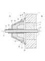
図1に示すように、建屋の一部を構成する壁部1は、第一の空間(図1においては、左方側の空間)S1と第二の空間(図1においては、右方側の空間)S2とを区画するものである。
As shown in FIG. 1, the
壁部1には、当該壁部1を軸線O方向(壁部1に対して直交する方向であって、図1においては左右方向)に貫通する貫通孔11が設けられており、この貫通孔11には、軸線O方向に沿って延びる配設部材(本実施例においては、管材)2が挿通されている。つまり、配設部材2は、壁部1の貫通孔11に挿通されることによって第一の空間S1と第二の空間S2とに跨って設けられている。
The
貫通孔11と配設部材2との間の空間(隙間)Gには、耐火シール材3が設けられている。耐火シール材3は、耐火性を有する材料から成り、貫通孔11と配設部材2との間の空間Gを閉塞するものである。よって、火災が発生した場合には、耐火シール材3によって第一の空間S1と第二の空間S2との間における火炎や煙等の流通が防止されるようになっている。
A
第一の空間S1は、壁部1に対して火災が発生すると想定される側の空間であり、この第一の空間S1には、火災による火炎(熱)から耐火シール材3を保護するためのシール保護部材4が設けられている。シール保護部材4は、配設部材2における所定の範囲に巻き付けられる断熱材21と、貫通孔11を覆う耐火カバー部材22と、この耐火カバー部材22の中に収納される耐火部材23および熱膨張耐火材24とから概略構成されている。
The first space S 1 is a space on the side where a fire is assumed to occur on the
断熱材21は、断熱性を有する材料から成るシート状のものであり、第一空間S1内における配設部材2の径方向外側に巻き付けられている。断熱材21は、第一の空間S1において火災が発生した際に火災(火炎)による熱が配設部材2を介して熱膨張耐火材24に伝達されないようにする(伝達され難くする)ためのものであり、貫通孔11および耐火シール材3の近傍から所定の範囲、すなわち、耐火カバー部材22ならびに当該耐火カバー部材22の中に収納されている耐火部材23および熱膨張耐火材24が配置される範囲に設けられている。
The
なお、断熱材21は、配設部材2に対して軸線O方向(配設部材2の配設方向であって、図1においては左右方向)に摺動可能に巻き付けられており、断熱材21と配設部材2との間に軸線方向Oの所定の力が作用した場合には、断熱材21と配設部材2とは、当該力の作用方向(軸線O方向)に相対的に移動するようになっている。
The
耐火カバー部材22は、耐火性を有する材料から成り、壁部1(貫通孔11)の側(図1においては、右方側)に開口する凹部(内面)31を有する略錐形状(円錐台形状)のものである。耐火カバー部材22には、壁部1から離れるに従って配設部材2に接近するように軸線Oに対して傾斜された傾斜部(テーパ形状部)32と、この傾斜部32の一方側(壁部1から遠い側であって、図1においては左方側)から軸線Oに対して直交する方向に延びる直交部(円盤形状部)33とが設けられている。
The
もちろん、本発明におけるカバー部材は、本実施例のように壁部1から離れるに従って配設部材2に接近する傾斜部32を有するもの、すなわち、壁部1から離れる方向に窄む形状から成るものであれば良く、本実施例のように円錐台形状のものに限定されない。本発明におけるカバー部材としては、例えば、角錐台形状、円錐形状または角錐形状のものであっても良い。
Of course, the cover member in the present invention has an inclined
耐火カバー部材22の直交部33には、軸線O方向に貫通する挿通孔34が当該直交部33の略中心に位置して設けられており、この挿通孔34には、断熱材21が巻き付けられた配設部材2が挿通されている。
The
耐火カバー部材22には、連結穴25aを有する第一継手部材25が傾斜部32の径方向外側であって軸線O方向他方側(壁部1に近い側であって、図1においては右方側)に位置して設けられおり、壁部1には、連結穴26aを有する第二継手部材26が第一の空間S1側(図1においては、左方側)に位置して設けられており、第一継手部材25と第二継手部材26とは、それぞれの連結穴25a,26aに挿通されたワイヤ(索条部材)27によって連結されている。
The
つまり、耐火カバー部材22は、ワイヤ27を介して壁部1と連結されており、壁部1に対して、壁部1に沿う方向(図1においては、上下方向)および壁部1と直交する方向(軸線O方向であって、図1においては左右方向)において移動が許容された状態にある。よって、壁部1と耐火カバー部材22とは、地震等の振動によって相対的に移動することができるようになっている。
That is, the
耐火部材23は、耐火性を有する材料から成り、耐火カバー部材22の内面31に沿うと共に、壁部1(貫通孔11)の側に開口する凹部41を有する略錐形状(円錐台形状)のものである。つまり、耐火部材23は、耐火カバー部材22の内面(凹部)31を覆うように設けられている。また、耐火部材23には、耐火カバー部材22における挿通孔34と同軸かつ同径の挿通孔42が設けられており、この挿通孔42には、断熱材21が巻き付けられた配設部材2が挿通されている。
The
熱膨張耐火材24は、耐火性を有すると共に熱膨張率の高い材料から成り、耐火部材23の凹部41を埋めるように設けられている。つまり、熱膨張耐火材24は、耐火部材23の凹部41に沿う略錐形状(円錐台形状)から成る。また、熱膨張耐火材24には、耐火カバー部材22の挿通孔34および耐火部材23の挿通孔42と同軸かつ同径の挿通孔51が設けられており、この挿通孔51には、断熱材21が巻き付けられた配設部材2が挿通されている。
The thermal expansion
本発明の実施例1に係る建屋貫通部のシール構造の作用について、図1、図2Aおよび図2Bを参照して説明する。 The effect | action of the seal structure of the building penetration part which concerns on Example 1 of this invention is demonstrated with reference to FIG.1, FIG.2A and FIG.2B.
まず、第一の空間S1において火災が発生した場合には、貫通孔11と配設部材2との間の空間(隙間)Gは、隙間なく充填された耐火シール材3によって閉塞されているため、火災による火炎や煙等が第一の空間S1から第二の空間S2へ流通することはない(図1参照)。
First, when a fire occurs in the first space S 1 , the space (gap) G between the through
また、貫通孔11と配設部材2との間の空間(隙間)Gに充填された耐火シール材3は、第一の空間S1において、シール保護部材4によって覆われている。つまり、耐火シール材3は、シール保護部材4によって火災の火炎(熱)から保護された状態にあるので、地震等によって耐火シール材3が劣化した状態に陥った場合においても、シール保護部材4が耐火シール材としての機能を発揮する。よって、建屋貫通部のシール構造における十分な耐火性能を確保することができる。
Further, the
次に、地震によって建屋が振動し、配設部材2が壁部1に対して軸線O方向一方側(図2Aにおいては、左方側)に移動した場合には、壁部1(耐火シール材3)とシール保護部材4との間に隙間g1が生じる(図2A参照)。
Next, when the building vibrates due to the earthquake and the
シール保護部材4における熱膨張耐火材24は、隙間g1が生じたことによって火災の火炎(熱)に曝されるため、熱膨張を起こす。熱膨張耐火材24の熱膨張は、隙間g1を閉塞するように壁部1に沿って進行し、耐火シール材3は、熱膨張された熱膨張耐火材24に覆われて火災の火炎(熱)から保護される。よって、耐火シール材3が地震等で劣化した場合においても、熱膨張された熱膨張耐火材24によって、建屋貫通部のシール構造としての十分な耐火性能を確保することができる。
Since the thermal expansion
シール保護部材4は、ワイヤ27を介して壁部1と連結されており、壁部1に対する移動が許容された状態にあるので、配設部材2と共に壁部1に対して軸線O方向一方側に移動することができる。よって、地震の振動によって耐火カバー部材22と壁部1との連結部(第一継手部材25、第二継手部材26およびワイヤ27)ならびに配設部材2等が損傷することなく、シール保護部材4および配設部材2は壁部1に対して軸線O方向に移動することができる。
The
また、シール保護部材4および配設部材2がワイヤ27を介した連結による許容分だけ移動されると、シール保護部材4は、ワイヤ27を介して壁部1に対する移動が制限されているので、シール保護部材4(断熱材21)と配設部材2との間には、軸線O方向の所定の力が作用する。この軸線O方向の所定の力が作用すると、シール保護部材4(断熱材21)と配設部材2とが相対的に移動(摺動)し、配設部材2のみが壁部1に対して軸線O方向に移動することとなる。
Further, when the
よって、配設部材2が大きく変位する場合には、シール保護部材4は、ワイヤ27による許容分だけ移動し、配設部材2は、シール保護部材4に対して更に移動(大きく変位)することができる。つまり、配設部材2が壁部1に対して大きく変位(軸線O方向に移動)したとしても、シール保護部材4はワイヤ27の連結によって許容される移動量のみ移動されるだけであり、壁部1および耐火シール材3とシール保護部材4との間の隙間g1が大きくなることはない。
Therefore, when the disposing
次に、地震によって建屋が振動し、配設部材2が軸線Oと直交する方向(壁部1に沿う方向であって、図2Bにおいては上下方向)に移動した場合には、壁部1とシール保護部材4との間には隙間は生じない(図2B参照)。ここで、図2Bにおいては、配設部材2およびシール保護部材4が壁部1に対して軸線Oと直交する方向に移動した状態であって、配設部材2の中心軸O1と軸線Oとが距離dを成す状態を示している。
Next, when the building vibrates due to the earthquake and the
よって、貫通孔11と配設部材2との間の空間(隙間)Gは、隙間なく充填された耐火シール材3によって閉塞されており、更にはシール保護部材4によって覆われているため、火災による火炎や煙等が第一の空間S1から第二の空間S2へ流通することはない。よって、建屋貫通部のシール構造における十分な耐火性能を確保することができる。
Therefore, the space (gap) G between the through-
シール保護部材4は、ワイヤ27を介して壁部1と連結されており、壁部1に対する移動が許容された状態にあるので、配設部材2と共に壁部1に対して軸線Oと直交する方向に移動することができる。よって、地震の振動によって耐火カバー部材22と壁部1との連結部(第一継手部材25、第二継手部材26およびワイヤ27)ならびに配設部材2等が損傷することなく、シール保護部材4および配設部材2は壁部1に対して軸線Oと直交する方向に移動することができる。
Since the
以上に説明したように、本実施例においては、建屋貫通部のシール構造として、建屋の壁部1に形成された貫通孔11に挿通される配設部材2と、前記貫通孔11と前記配設部材2との間の空間Gを閉塞する耐火シール材3と、前記配設部材2と相対的に移動可能な状態で前記壁部1とワイヤ(索条部材)27によって連結され、前記壁部1側に開口する凹部31を有して前記耐火シール材3を覆うように設けられる耐火カバー部材22と、前記耐火カバー部材22の凹部31に設けられ、前記壁部1側に開口する凹部41を有する耐火部材23と、前記耐火部材23の凹部41に設けられる熱膨張耐火材24とを備えている。
As described above, in the present embodiment, as the seal structure of the building penetration part, the disposing
この構成によれば、地震等によって配設部材2が大きく変位した場合であっても、壁部1(耐火シール材3)と耐火部材23および熱膨張耐火材24との間に熱膨張耐火材24の熱膨張によって塞ぐことができない程度に大きい隙間が生じることはなく、貫通孔11と配設部材2との間に設けられた耐火シール材3と熱膨張された熱膨張耐火材24によって、建屋貫通部のシール構造としての十分な耐火性能を確保することができる。
According to this configuration, even when the disposing
[実施例2]
本発明の実施例2に係る建屋貫通部のシール構造の構造について、図3から図7ならびに図9Aおよび図9Bを参照して説明する。
[Example 2]
The structure of the seal structure of the building penetration part according to the second embodiment of the present invention will be described with reference to FIGS. 3 to 7 and FIGS. 9A and 9B.
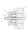
図3に示すように、建屋の一部を構成する壁部101は、第一の空間(図3においては、左方側の空間)S1と第二の空間(図3においては、右方側の空間)S2とを区画するものである。
As shown in FIG. 3, the
壁部101には、当該壁部101を軸線O方向(壁部101に対して直交する方向であって、図3においては左右方向)に貫通する貫通孔111が設けられており、この貫通孔111には、軸線O方向に沿って延びる配設部材(本実施例においては、管材)102が挿通されている。つまり、配設部材102は、壁部101の貫通孔111に挿通されることによって第一の空間S1と第二の空間S2とに跨って設けられている。
The
貫通孔111と配設部材102との間の空間(隙間)Gには、耐火シール材103が設けられている。耐火シール材103は、耐火性を有する材料から成り、貫通孔111と配設部材102との間の空間Gを閉塞するものである。よって、火災が発生した場合には、耐火シール材103によって第一の空間S1と第二の空間S2との間における火炎や煙等の流通が防止されるようになっている
A
第一の空間S1は、壁部101に対して火災が発生すると想定される側の空間であり、この第一の空間S1には、火災による火炎(熱)から耐火シール材103を保護するためのシール保護部材104が設けられている。シール保護部材104は、配設部材102における所定の範囲に巻き付けられる断熱材121と、貫通孔111を覆う耐火部材122と、この耐火部材122の中に収納されるカートリッジ123および熱膨張耐火材124とから概略構成されている。
The first space S 1 is a space on the side where a fire is assumed to occur with respect to the
断熱材121は、断熱性を有する材料から成るシート状のものであり、第一空間S1内における配設部材102の径方向外側に巻き付けられている。断熱材121は、第一の空間S1において火災が発生した際に火災(火炎)による熱が配設部材102を介して熱膨張耐火材124に伝達されないようにする(伝達され難くする)ためのものであり、貫通孔111および耐火シール材103の近傍から所定の範囲、すなわち、耐火部材122ならびに当該耐火部材122の中に収納されているカートリッジ123および熱膨張耐火材124が配置される範囲に設けられている。
The
耐火部材122は、耐火性を有する材料から成り、壁部101(貫通孔111)の側(図3においては、右方側)に開口する凹部131を有する略柱形状(円柱形状)のものである。耐火部材122には、配設部材102と平行(軸線O方向)に延びる略円筒形状の円筒部132と、円筒部132の一方側(壁部101から遠い側であって、図3においては左方側)から軸線Oに対して直交する方向に延びる略円盤形状の円盤部133とが設けられている。
The fire-
図3および図5に示すように、耐火部材122の円筒部132には、円盤部133と一体に設けられる第一円筒部(図3および図5においては、下方側部分)132aと、円盤部133および第一円筒部132aと別体に設けられる第二円筒部(図3および図5においては、上方側部分)132bとが設けられている。つまり、耐火部材122は、円盤部(第一耐火部材)133および第一円筒部(第一耐火部材)132aに対して第二円筒部(第二耐火部材)132bが着脱可能に設けられた分割構造から成る。
As shown in FIGS. 3 and 5, the
円筒部132の径方向外側には、第一円筒部132aに対して第二円筒部132bを固定するための固定バンド125が巻き付けられている。なお、後述する熱膨張耐火材124の交換は、固定バンド125を円筒部132の径方向外側から取り外し、第二円筒部132bを第一円筒部132aから離脱させて行われる。
A fixing
もちろん、本発明における耐火部材は、本実施例のように円柱形状のものに限定されず、例えば、角柱形状、錐形状、錐台形状のものであっても良い。 Of course, the refractory member in the present invention is not limited to a cylindrical shape as in this embodiment, and may be, for example, a prismatic shape, a cone shape, or a truncated cone shape.
なお、図9Aおよび図9Bに示すように、耐火部材122における第二円筒部132bを離脱させた状態においては、耐火部材122における第二円筒部132bが装着されていた部分が空所135となるので、当該空所135を利用してカートリッジ123(本実施例においては、十個のカートリッジ123)を耐火部材122の凹部131に対して出し入れ(供給および排出)することができる。
9A and 9B, in the state where the second
図3に示すように、耐火部材122の円盤部133には、軸線O方向に貫通する挿通孔134が当該円盤部133の略中心に位置して設けられており、この挿通孔134には、断熱材121が巻き付けられた配設部材102が挿通されている。
As shown in FIG. 3, an
図3および図5に示すように、カートリッジ123は、扇台形状の袋構造を成し、耐火部材122内すなわち円柱状の凹部131において周方向に複数(本実施例においては、十個)並んで設けられている。つまり、カートリッジ123は、耐火部材122における凹部131内の空間を周方向に分割(区画)するものである。
As shown in FIGS. 3 and 5, the
図3、図5および図6に示すように、カートリッジ123には、耐火部材122の凹部131であって円筒部132の内面に沿って延びる外周面141と、配設部材102に巻き付けられる断熱材121の外面に沿って延びる内周面142と、外周面141と内周面142とを繋いで円盤部133の内面(耐火部材122の凹部131)に沿って延びる底面143と、外周面141と内周面142と底面143とを繋いで耐火部材122(凹部131)内の空間を周方向に区画する側面144,145とが設けられている。
As shown in FIGS. 3, 5, and 6, the
また、カートリッジ123には、熱膨張耐火材124が収納されており、この熱膨張耐火材124の脱落を防止するための返し部(脱落防止構造)146,147が設けられている。返し部146,147は、外周面141および内周面142の一方側端縁部(開口側の端縁部であって、図3においては右方側の端縁部、図6においては紙面手前側の端縁部)から対向して突出するように形成されている。
Further, the
なお、熱膨張耐火材124の脱落を防止する返し部146,147は、本実施例のように外周面141および内周面142の端縁部に形成されるものに限定されず、熱膨張耐火材124が脱落する方向(図3においては、右方側)に移動する際に抵抗となるものであれば良い。例えば、図4に示すように、返し部146,147を、カートリッジ123における外周面141、内周面142または側面144,145の少なくともいずれか一つにおいて、当該カートリッジ123内に向かって延びるように形成しても良い。
The
また、図6および図7に示すように、カートリッジ123は、その両側面144,145が外周面141および内周面142よりも軸線O方向(図7においては、左右方向)に短く形成されており、カートリッジ123に収納された熱膨張耐火材124は、周方向(図7においては、上下方向)に隣接して配置されるカートリッジ123に収納された熱膨張耐火材124と接触(密接)するようになっている。
Further, as shown in FIGS. 6 and 7, the
つまり、周方向に隣接して配置されるカートリッジ123に収納された熱膨張耐火材124は、互いに接触(密接)するように設けられており、第一の空間S1における火災によって熱膨張する場合には、周方向に隙間なく熱膨張し、耐火シール材103を確実に保護することができるようになっている。
That is, the thermally expanded
また、図5に示すように、周方向に並んで設けられる複数(本実施例においては、十個)のカートリッジ123(123a〜123j)のうち一部のカートリッジ123(123b〜123e,123f〜123i)は、ヒンジ151を介して連結されている。ヒンジ151は、外周面141と少なくとも一方の側面144,145との間の角部に設けられており、ヒンジ151を介して連結されたカートリッジ123は、軸方向(軸線O方向)と直交する方向において互い(相対的)に回転可能となっている(図9B参照)。
Further, as shown in FIG. 5, some of the cartridges 123 (123b to 123e, 123f to 123i) among a plurality (ten in this embodiment) of the cartridges 123 (123a to 123j) provided side by side in the circumferential direction. Are connected via a
本実施例においては、図5に示すように、第二円筒部132bの近傍(図5においては、上方側)に位置するカートリッジ123a,123jは、ヒンジ151を介して連結されていないもの(独立した状態のもの)であり、カートリッジ123aを除いて一方側(図5においては、右方側)に位置するカートリッジ123b〜123e、および、カートリッジ123jを除いて他方側(図5においては、左方側)に位置するカートリッジ123f〜123iは、それぞれヒンジ151を介して連結されているものである。
In this embodiment, as shown in FIG. 5, the
本発明の実施例2に係る建屋貫通部のシール構造の作用について、図3、図8、図9Aおよび図9Bを参照して説明する。 The effect | action of the seal structure of the building penetration part which concerns on Example 2 of this invention is demonstrated with reference to FIG.3, FIG.8, FIG.9A and FIG. 9B.
まず、第一の空間S1において火災が発生した場合には、貫通孔111と配設部材102との間の空間(隙間)Gは、隙間なく充填された耐火シール材103によって閉塞されているため、火災による火炎や煙等が第一の空間S1から第二の空間S2へ流通することはない(図3参照)。
First, when a fire occurs in the first space S 1 , the space (gap) G between the through
また、貫通孔111と配設部材102との間の空間(隙間)Gに充填された耐火シール材103は、第一の空間S1において、シール保護部材104によって覆われている。つまり、耐火シール材103は、シール保護部材104によって火災の火炎(熱)から保護された状態にあるので、地震等によって耐火シール材103が劣化した状態に陥った場合においても、シール保護部材104が耐火シール材としての機能を発揮する。よって、建屋貫通部のシール構造における十分な耐火性能を確保することができる。
Further, the
次に、地震によって建屋が振動し、配設部材102が壁部101に対して移動した場合には、壁部101(耐火シール材103)とシール保護部材104との間に隙間gが生じる(図8参照)。
Next, when the building vibrates due to the earthquake and the
シール保護部材104における熱膨張耐火材124は、隙間gが生じたことによって火災の火炎(熱)に曝されるため、熱膨張を起こす。熱膨張耐火材124の熱膨張は、隙間gを閉塞するように壁部101に沿って進行し、耐火シール材103は、熱膨張された熱膨張耐火材124に覆われて火災の火炎(熱)から保護される。よって、耐火シール材103が地震等で劣化した場合においても、熱膨張された熱膨張耐火材124によって、建屋貫通部のシール構造としての十分な耐火性能を確保することができる。
The thermal expansion
次に、定期点検等において熱膨張耐火材124の交換が必要な場合には、以下に示す交換作業を行う。
Next, when it is necessary to replace the thermally expanded
まず、固定バンド125を耐火部材122(円筒部132)の径方向外側から取り外し、耐火部材122における第一円筒部132aおよび円盤部133から第二円筒部132bを離脱する(図9A参照)。
First, the fixing
次に、第二円筒部132bの離脱によって形成された空所135を利用し、耐火部材122の凹部131に収納されてヒンジ151を介して連結されていない(図9Aにおいては、上方側に位置する)カートリッジ123a,123jを抜き出す。
Next, using the
次に、ヒンジ151を介して連結されている一方(図9Bにおいては、左方側)のカートリッジ123f〜123iを耐火部材122の凹部131内にて周方向一方側へ回転(図9Bにおいては、右回転)する。
Next, one of the
この回転によって、ヒンジ151を介して連結されているカートリッジ123f〜123iのうち一方側(図9Bにおいては、上方側)のカートリッジ123iが前述した空所135に位置し、周方向に隣接して配置されたカートリッジ123hに対してヒンジ151回りに回転可能となる。つまり、カートリッジ123iをカートリッジ123hに対してヒンジ151回りに回転(図9Bにおいては、左回転)することにより、当該カートリッジ123iを凹部131内から抜き出すことができる。
By this rotation, the
前述したカートリッジ123iと同様にして、ヒンジ151を介して連結されている一方のカートリッジ123f〜123iにおける残りのカートリッジ123f,123g,123hを凹部131内にて周方向一方側へ回転し、ヒンジ151を利用して空所135から順に抜き出す。これにより、ヒンジ151を介して連結されている一方のカートリッジ123f〜123iを耐火部材122の凹部131内から取り出すことができる。
In the same manner as the
次に、ヒンジ151を介して連結されている他方(図9Bにおいては、右方側)のカートリッジ123b〜123eを、前述した一方のカートリッジ123f〜123iと同様にして、凹部131内から抜き出す。なお、他のカートリッジ123a、123f〜123jは既に抜き出されているので、カートリッジ123b〜123eを耐火部材122の凹部131内にて周方向に回転する場合には、一方側または他方側のいずれの方向の回転(図9Bにおいては、右回転または左回転)であっても良い。
Next, the
そして、耐火部材122の凹部131内から抜き出したカートリッジ123a〜123jの中に収納された熱膨張耐火材124を取り出し、当該カートリッジ123a〜123jの中に新たな熱膨張耐火材124を収納(充填)する。
Then, the thermal expansion
次に、カートリッジ123a〜123jを凹部131内から抜き出した手順の逆の手順によって、カートリッジ123a〜123jを耐火部材122の凹部131内に収納する。
Next, the
つまり、第二円筒部132bの離脱によって形成された空所135から、ヒンジ151を介して連結されている他方のカートリッジ123b〜123eおよび一方のカートリッジ123f〜123iをヒンジ151による回転を利用して耐火部材122の凹部131内に順に収納し、最後にヒンジ151を介して連結されていない(独立した)カートリッジ123a,123jを耐火部材122の凹部131内に収納する。そして、第二円筒部132bを第一円筒部132aおよび円盤部133に装着し、耐火部材122の径方向外側に固定バンド125を取り付ける。
That is, the
以上の手順により、耐火部材122内における熱膨張耐火材124の交換作業は完了する。
With the above procedure, the replacement work of the thermally expanded
以上に説明したように、本実施例においては、建屋貫通部のシール構造として、建屋の壁部101に形成された貫通孔111に挿通される配設部材102と、前記貫通孔111と前記配設部材102との間の空間Gを閉塞する耐火シール材103と、前記壁部101側に開口する凹部131を有して前記耐火シール材103を覆うように設けられる耐火部材122と、前記凹部131に設けられて熱によって膨張する熱膨張耐火材124とを備え、前記耐火部材122が、第一円筒部(第一耐火部材)132aと第二円筒部(第二耐火部材)132bとを備えた分割構造であり、前記第一円筒部(第一耐火部材)132aに対して前記第二円筒部(第二耐火部材)132bを離脱した状態で前記熱膨張耐火材124を前記凹部131に供給可能な空所135を有する。
As described above, in the present embodiment, the seal structure of the building penetration part is the
この構成によれば、耐火部材122の全部を配設部材102から取り外すことなく、熱膨張耐火材124の交換を行うことができるので、交換作業に掛かる時間を短縮することができる。
According to this configuration, since the thermal expansion
なお、カートリッジ123a〜123jを耐火部材122の凹部131に収納する際に、カートリッジ123の径方向内側および径方向外側に図示しないシム(薄板状部材)を挿入することにより、カートリッジ123と耐火部材122および断熱材21との引っ掛かりを防止し、カートリッジ123を耐火部材122の凹部131にて円滑に移動(回転)することができる。つまり、図示しないシムを用いることによって、熱膨張耐火材24の交換作業に掛かる時間をより短縮することができる。
When the
[実施例3]
本発明の実施例3に係る建屋貫通部のシール構造の構造について、図10を参照して説明する。
[Example 3]
The structure of the seal structure of the building penetration part which concerns on Example 3 of this invention is demonstrated with reference to FIG.
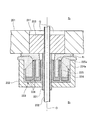
図10に示すように、建屋の一部を構成する壁部201は、第一の空間(図10においては、下方側の空間)S1と第二の空間(図10においては、上方側の空間)S2とを区画するものである。
As shown in FIG. 10, the
壁部201には、当該壁部201を軸線O方向(壁部201に対して直交する方向であって、図10においては上下方向)に貫通する貫通孔211が設けられており、この貫通孔211には、軸線O方向に沿って延びる配設部材(本実施例においては、管材)202が挿通されている。つまり、配設部材202は、壁部201の貫通孔211に挿通されることによって第一の空間S1と第二の空間S2とに跨って設けられている。
The
貫通孔211と配設部材202との間の空間(隙間)Gには、耐火シール材203が設けられている。耐火シール材203は、耐火性を有する材料から成り、貫通孔211と配設部材202との間の空間Gを閉塞するものである。よって、火災が発生した場合には、耐火シール材203によって第一の空間S1と第二の空間S2との間における火炎や煙等の流通が防止されるようになっている。
A
第一の空間S1は、壁部201に対して火災が発生すると想定される側の空間であり、この第一の空間S1には、火災による火炎(熱)から耐火シール材203を保護するためのシール保護部材204が設けられている。シール保護部材204は、配設部材202における所定の範囲に巻き付けられる断熱材221と、貫通孔211を覆う耐火部材222と、この耐火部材222の中に収納されるフレーム部材223および熱膨張耐火材224,225とから概略構成されている。
The first space S 1 is a space on the side on which a fire is assumed to occur with respect to the
断熱材221は、断熱性を有する材料から成るシート状のものであり、第一空間S1内における配設部材202の径方向外側に巻き付けられている。断熱材221は、第一の空間S1において火災が発生した際に火災(火炎)による熱が配設部材202を介して熱膨張耐火材224,225に伝達されないようにする(伝達され難くする)ためのものであり、貫通孔211および耐火シール材203の近傍から所定の範囲、すなわち、耐火部材222ならびに当該耐火部材222の中に収納されているフレーム部材223および熱膨張耐火材224,225が配置される範囲に設けられている。
Heat insulating
耐火部材222は、耐火性を有する材料から成り、壁部201(貫通孔211)の側(図10においては、上方側)に開口する凹部231を有する略柱形状(円柱形状)のものである。耐火部材222には、配設部材202と平行(軸線O方向)に延びる略円筒形状の円筒部232と、円筒部232の一方側(壁部201から遠い側であって、図10においては下方側)から軸線Oに対して直交する方向に延びる略円盤形状の円盤部233とが設けられている。
The fire-
もちろん、本発明における耐火部材は、本実施例のように円柱形状のものに限定されず、例えば、角柱形状、錐形状、錐台形状のものであっても良い。 Of course, the refractory member in the present invention is not limited to a cylindrical shape as in this embodiment, and may be, for example, a prismatic shape, a cone shape, or a truncated cone shape.
耐火部材222の円盤部233には、軸線O方向に貫通する挿通孔234が当該円盤部233の略中心に位置して設けられており、この挿通孔234には、断熱材221が巻き付けられた配設部材202が挿通されている。
The
フレーム部材223は、壁部201(貫通孔211)の側(図10においては、上方側)に開口する二つの凹部241,242を有する円柱形状のものである。フレーム部材223には、耐火部材222の凹部231であって円筒部232の内面に沿って延びる環状の外側リング部243と、外側リング部243と同心状であって径を異にする(外側リング部243よりも径の小さい)環状の中間リング部244と、外側リング部243および中間リング部244と同心状であって径を異にする(外側リング部243および中間リング部244よりも径の小さい)環状の内側リング部245と、これら外側リング部243と中間リング部244と内側リング部245とを一方側(図10においては、下方側)で接続する円盤状の接続部246とが設けられている。
The
つまり、フレーム部材223は、外側リング部243と中間リング部244と接続部246とによって形成される環状の第一凹部(環状凹部)241と、中間リング部244と内側リング部245と接続部246とによって形成される環状の第二凹部(環状凹部)242とを有するものである。ここで、第一凹部241と第二凹部242とは、同心状であって径を異にする環状溝であり、第一凹部241は第二凹部242よりも大きい径の環状溝である。
That is, the
つまり、第一凹部241および第二凹部242は、フレーム部材223において径方向に二段で設けられた環状溝であり、第一凹部241は径方向外側に位置する環状溝であり、第二凹部242は径方向内側に位置する環状溝である。
That is, the first
これら第一凹部241および第二凹部242には、膨張率を異にする熱膨張耐火材224,225が収納(充填)されている。第一凹部241に収納されている第一熱膨張耐火材224は、第二凹部242に収納されている第二熱膨張耐火材225と比較して、固まり易い(流動的でない)ものであり、第二熱膨張耐火材225は、第一熱膨張耐火材224と比較して、膨張率の高いものである。
Thermal expansion
また、第一凹部241における底部(接続部246側の部分)には、断熱材226が設けられており、この断熱材226によって、火災(火炎)による熱が接続部246側から第一熱膨張耐火材224に伝達されないように(伝達され難く)なっている。
In addition, a
また、第二凹部242における底部(接続部246側の部分)と外周部(中間リング部244側の部分)と内周部(内側リング部245側の部分)には、断熱材226が設けられており、この断熱材226によって、火災(火炎)による熱が接続部246側、中間リング部244側および内側リング部245側から第二熱膨張耐火材225に伝達されないように(伝達され難く)なっている。
In addition, a
また、外側リング部243は、中間リング部244および内側リング部245と比較して軸線O方向に短く形成されている。そして、第一凹部241に収納された第一熱膨張耐火材224の表面224aは、径方向外側に向けて傾斜しており、火災による火炎(熱)の影響を受け易い状態にある。一方、第二凹部242に収納された第二熱膨張耐火材225の表面225aは、壁部201側に向いて耐火シール材203と接触し、火災による火炎(熱)の影響を受け難い状態にある。
Further, the
本発明の実施例3に係る建屋貫通部のシール構造の作用について、図10、図11Aおよび図11Bを参照して説明する。 The effect | action of the seal structure of the building penetration part which concerns on Example 3 of this invention is demonstrated with reference to FIG. 10, FIG. 11A and FIG. 11B.
まず、第一の空間S1において火災が発生した場合には、貫通孔211と配設部材202との間の空間(隙間)Gは、隙間なく充填された耐火シール材203によって閉塞されているため、火災による火炎や煙等が第一の空間S1から第二の空間S2へ流通することはない(図10参照)。
First, when a fire occurs in the first space S 1 , the space (gap) G between the through
また、貫通孔211と配設部材202との間の空間(隙間)Gに充填された耐火シール材203は、第一の空間S1において、シール保護部材204によって覆われている。つまり、耐火シール材203は、火災の火炎(熱)から保護された状態にあるので、地震等によって耐火シール材203が劣化した状態に陥った場合においても、シール保護部材204が耐火シール材としての機能を発揮する。よって、建屋貫通部のシール構造における十分な耐火性能を確保することができる。
In addition, the
次に、地震によって建屋が振動し、配設部材202が壁部201に対して移動した場合には、壁部201(耐火シール材203)とシール保護部材204との間に隙間g1が生じる(図11A参照)。
Next, when the building vibrates due to the earthquake and the
このとき、第一熱膨張耐火材224は、耐火部材222内において径方向外側に位置すると共に、その表面224aが径方向外側に向けて傾斜しているので、隙間g1が生じたことによる火災の火炎(熱)に影響を受け易い。
At this time, the first thermal expansion
一方、第二熱膨張耐火材225は、耐火部材222内において径方向内側に位置すると共に、断熱材226によって保護された状態にあるので、隙間g1が生じたことによる火災の火炎(熱)に影響を受け難い。また、第二熱膨張耐火材225は、その表面225aが壁部201側に向いているので、隙間g1が生じたことによる火災の火炎(熱)に影響を受け難い。
On the other hand, the second thermal expansion
よって、壁部201(耐火シール材203)とシール保護部材204との間に隙間g1が生じた場合には、まず、第一熱膨張耐火材224が火災の火炎(熱)によって熱膨張を起こすこととなる。
Therefore, when the gap g 1 is generated between the wall 201 (fireproof sealant 203) and the
第一熱膨張耐火材224の熱膨張は、隙間g1を閉塞するように壁部201に沿って進行し、耐火シール材203は、熱膨張された第一熱膨張耐火材224に覆われて火災の火炎(熱)から保護される。よって、耐火シール材203が地震等で劣化した場合においても、熱膨張された第一熱膨張耐火材224によって、建屋貫通部のシール構造としての十分な耐火性能を確保することができる。
The thermal expansion of the first thermal expansion
このとき、熱膨張された第一熱膨張耐火材224によって、耐火シール材203と共に、第二熱膨張耐火材225が火災の火炎(熱)から保護される。よって、第二熱膨張耐火材225が第一熱膨張耐火材224と共に熱膨張してしまうことはない。
At this time, the thermally expanded first thermally expanded
そして、第一熱膨張耐火材224が熱膨張した後に、余震等によって劣化してしまうと、熱膨張した第一熱膨張耐火材224と壁部201との間に、新たな隙間g2が生じる(図11B参照)。
Then, after the first thermal expansion
シール保護部材204における第二熱膨張耐火材225は、隙間g2が生じたことによって火災の火炎(熱)に曝されるため、熱膨張を起こす。第二熱膨張耐火材225の熱膨張は、隙間g2を閉塞するように壁部201に沿って進行し、耐火シール材203は、熱膨張された第二熱膨張耐火材225に覆われて火災の火炎(熱)から保護される。よって、第一熱膨張材224が余震等で劣化した場合においても、熱膨張された第二熱膨張耐火材225によって、建屋貫通部のシール構造としての更に十分な耐火性能を確保することができる。
Since the second thermal expansion
以上に説明したように、本実施例においては、建屋貫通部のシール構造として、建屋の壁部201に形成された貫通孔211に挿通される配設部材202と、前記貫通孔211と前記配設部材202との間の空間Gを閉塞する耐火シール材203と、前記壁部201側に開口する凹部231を有して前記耐火シール材203を覆うように設けられる耐火部材222と、前記凹部231に設けられて熱によって膨張する熱膨張耐火材224,225とを備え、前記熱膨張耐火材224,225が、前記凹部231において前記配設部材202を中心として径方向に二段(複数段)に設けられる。
As described above, in the present embodiment, the seal structure of the building penetrating portion has the
この構成によれば、第一熱膨張耐火材224と第二熱膨張耐火材225とを段階的に熱膨張させることにより、建屋貫通部のシール構造としての耐火性能を十分に確保することができる。
According to this configuration, the first thermal expansion
なお、本実施例においては、耐火部材222の中に第一熱膨張耐火材224および第二熱膨張耐火材225を収納し、地震によって建屋が振動して隙間g1が生じた際に第一熱膨張耐火材224が熱膨張するようにしているが、第一の空間S1において火災が発生した際に、第一熱膨張耐火材224を積極的に熱膨張するようにしても良い。
In the present embodiment, the first thermal expansion
例えば、図12に示すように、壁部201と耐火部材222(円筒部232)との間に隙間dを設けることにより、第一の空間S1において火災が発生した際に、第一熱膨張耐火材224が熱膨張する。このように第一熱膨張耐火材224を積極的に熱膨張させることにより、火災時における建屋貫通部のシール構造としての耐火性能を向上させることができる。
For example, as shown in FIG. 12, by providing the gap d between the
また、壁部201と耐火部材222(円筒部232)との間の隙間dを小さくまたは大きくすることにより、火災の火炎(熱)による第一熱膨張耐火材224の熱膨張への影響、すなわち、第一熱膨張耐火材224が熱膨張を起こすタイミングを制御することができる。
Further, by reducing or increasing the gap d between the
本発明は、建屋貫通部のシール構造に関するものであり、ガスタービンまたは蒸気タービン等を収容する建屋および建屋を備えた発電プラント、化学プラントならびに船舶などにおいて有益に利用することができる。 The present invention relates to a seal structure for a building penetrating portion, and can be beneficially used in a power generation plant, a chemical plant, a ship, and the like that include a building that houses a gas turbine or a steam turbine.
1 壁部
2 配設部材(管材)
3 耐火シール材
4 シール保護部材
11 貫通孔
21 断熱材
22 耐火カバー部材
23 耐火部材
24 熱膨張耐火材
25 第一継手部材
25a 連結穴
26 第二継手部材
26a 連結穴
27 ワイヤ(索条部材)
31 耐火カバー部材の凹部(内面)
32 耐火カバー部材の傾斜部(テーパ形状部)
33 耐火カバー部材の直交部(円盤形状部)
34 耐火カバー部材の挿通孔
41 耐火部材の凹部
42 耐火部材の挿通孔
51 熱膨張耐火材の挿通孔
101 壁部
102 配設部材(管材)
103 耐火シール材
104 シール保護部材
111 貫通孔
121 断熱材
122 耐火部材
123 カートリッジ
124 熱膨張耐火材
125 固定バンド
131 耐火部材の凹部
132 耐火部材の円筒部
132a 耐火部材の第一円筒部(第一耐火部材)
132b 耐火部材の第二円胴部(第二耐火部材)
133 耐火部材の円盤部(第一耐火部材)
134 耐火部材の挿通孔
135 耐火部材の空所
141 カートリッジの外周面
142 カートリッジの内周面
143 カートリッジの底面
144 カートリッジの側面
145 カートリッジの側面
146 カートリッジの返し部(脱落防止構造)
147 カートリッジの返し部(脱落防止構造)
151 ヒンジ
201 壁部
202 配設部材(管材)
203 耐火シール材
204 シール保護部材
211 貫通孔
221 断熱材
222 耐火部材
223 フレーム部材
224 第一熱膨張耐火材
225 第二熱膨張耐火材
226 断熱材
231 耐火部材の凹部
232 耐火部材の円筒部
233 耐火部材の円盤部
234 耐火部材の挿通孔
241 フレーム部材の第一凹部(環状凹部)
242 フレーム部材の第二凹部(環状凹部)
243 フレーム部材の外周リング部
244 フレーム部材の中間リング部
245 フレーム部材の内周リング部
246 フレーム部材の接続部
1
3
31 Recessed part (inner surface) of fireproof cover member
32 Inclined part of fireproof cover member (tapered part)
33 Orthogonal part (disc-shaped part) of fireproof cover member
34 Fire-resistant cover
103 Fire-
132b Second cylinder portion of the refractory member (second refractory member)
133 Disc part of refractory member (first refractory member)
134 Fire-resistant
147 Cartridge return (drop-off prevention structure)
203
242 Second recess of the frame member (annular recess)
243 Frame member
Claims (11)
前記貫通孔と前記配設部材との間の空間を閉塞する耐火シール材と、
前記配設部材と相対的に移動可能な状態で前記壁部と索条部材によって連結され、前記壁部側に開口する凹部を有して前記耐火シール材を覆うように設けられるカバー部材と、
前記カバー部材の凹部に設けられ、前記壁部側に開口する凹部を有する耐火部材と、
前記耐火部材の凹部に設けられる熱膨張耐火材と
を備えたことを特徴とする建屋貫通部のシール構造。 An arrangement member inserted through a through hole formed in the wall of the building;
A fireproof sealing material that closes a space between the through hole and the arrangement member;
A cover member that is connected by the wall member and the striated member in a state of being movable relative to the arrangement member, and has a recess opening on the wall portion side so as to cover the fireproof sealing material;
A refractory member provided in a recess of the cover member and having a recess that opens to the wall side;
A thermal expansion refractory material provided in a recess of the refractory member.
ことを特徴とする請求項1に記載の建屋貫通部のシール構造。 The seal structure of a building penetration part according to claim 1, wherein the cover member has a shape that narrows in a direction away from the wall part.
前記耐火部材が、第一耐火部材と第二耐火部材とを備えた分割構造であり、前記第一耐火部材に対して前記第二耐火部材を離脱した状態で前記熱膨張耐火材を前記凹部に供給可能な空所を有するものである
ことを特徴とする建屋貫通部のシール構造。 There is a disposing member inserted into a through hole formed in the wall of the building, a fireproof sealing material that closes a space between the through hole and the disposing member, and a recess opening on the wall side. In the seal structure of the building penetrating portion provided with a fireproof member provided so as to cover the fireproof sealant and a thermal expansion fireproof material provided in the recess and expanded by heat,
The fire-resistant member is a divided structure including a first fire-resistant member and a second fire-resistant member, and the thermally expanded fire-resistant material is placed in the recess in a state where the second fire-resistant member is detached from the first fire-resistant member. A seal structure for a building penetration, characterized by having a space that can be supplied.
ことを特徴とする請求項3に記載の建屋貫通部のシール構造。 4. The building penetrating part according to claim 3, further comprising a bag-structured cartridge that is arranged in a circumferential direction so as to surround the arrangement member in the recess and is capable of being filled with the thermally expanded refractory material. Seal structure.
ことを特徴とする請求項4に記載の建屋貫通部のシール構造。 The seal structure for a building penetrating part according to claim 4, wherein some of the cartridges arranged in the circumferential direction are connected via a hinge.
ことを特徴とする請求項4または請求項5に記載の建屋貫通部のシール構造。 The seal structure for a building penetrating part according to claim 4 or 5, wherein the cartridge is provided with a drop-off preventing structure for preventing the thermal expansion refractory from falling off.
前記熱膨張耐火材が、前記凹部において前記配設部材を中心として径方向に複数段に設けられるものである
ことを特徴とする建屋貫通部のシール構造。 There is a disposing member inserted into a through hole formed in the wall of the building, a fireproof sealing material that closes a space between the through hole and the disposing member, and a recess opening on the wall side. In the seal structure of the building penetrating portion provided with a fireproof member provided so as to cover the fireproof sealant and a thermal expansion fireproof material provided in the recess and expanded by heat,
The thermal expansion refractory material is provided in a plurality of stages in the radial direction around the arrangement member in the recess.
複数の前記環状凹部が、同心状であって径を異にするものであり、
前記熱膨張耐火材が、複数の前記環状凹部に収納されるものである
ことを特徴とする請求項7に記載の建屋貫通部のシール構造。 A frame member provided in the recess and having a plurality of annular recesses that open annularly toward the wall portion;
The plurality of annular recesses are concentric and have different diameters,
The said thermal expansion refractory material is accommodated in the said several annular recessed part. The seal structure of the building penetration part of Claim 7 characterized by the above-mentioned.
ことを特徴とする請求項8に記載の建屋貫通部のシール構造。 The seal structure for a building penetration part according to claim 8, wherein the thermal expansion refractory materials housed in the plurality of annular recesses have different expansion rates.
ことを特徴とする建屋。 A building comprising the seal structure for a building penetrating portion according to any one of claims 1 to 9.
ことを特徴とする発電プラント。 A power plant comprising the building according to claim 10.
Priority Applications (3)
| Application Number | Priority Date | Filing Date | Title |
|---|---|---|---|
| JP2016061478A JP6656974B2 (en) | 2016-03-25 | 2016-03-25 | Seal structure of building penetration portion, building provided with the seal structure, and power plant provided with the building |
| JP2019204039A JP6949923B2 (en) | 2016-03-25 | 2019-11-11 | Seal structure of building penetration, building with the seal structure, and power plant with the building |
| JP2019204038A JP6896829B2 (en) | 2016-03-25 | 2019-11-11 | Seal structure of building penetration, building with the seal structure, and power plant with the building |
Applications Claiming Priority (1)
| Application Number | Priority Date | Filing Date | Title |
|---|---|---|---|
| JP2016061478A JP6656974B2 (en) | 2016-03-25 | 2016-03-25 | Seal structure of building penetration portion, building provided with the seal structure, and power plant provided with the building |
Related Child Applications (2)
| Application Number | Title | Priority Date | Filing Date |
|---|---|---|---|
| JP2019204039A Division JP6949923B2 (en) | 2016-03-25 | 2019-11-11 | Seal structure of building penetration, building with the seal structure, and power plant with the building |
| JP2019204038A Division JP6896829B2 (en) | 2016-03-25 | 2019-11-11 | Seal structure of building penetration, building with the seal structure, and power plant with the building |
Publications (2)
| Publication Number | Publication Date |
|---|---|
| JP2017172748A true JP2017172748A (en) | 2017-09-28 |
| JP6656974B2 JP6656974B2 (en) | 2020-03-04 |
Family
ID=59970764
Family Applications (1)
| Application Number | Title | Priority Date | Filing Date |
|---|---|---|---|
| JP2016061478A Active JP6656974B2 (en) | 2016-03-25 | 2016-03-25 | Seal structure of building penetration portion, building provided with the seal structure, and power plant provided with the building |
Country Status (1)
| Country | Link |
|---|---|
| JP (1) | JP6656974B2 (en) |
Cited By (7)
| Publication number | Priority date | Publication date | Assignee | Title |
|---|---|---|---|---|
| CN109193520A (en) * | 2018-10-16 | 2019-01-11 | 广州供电局有限公司 | The plugging structure and its construction method of cable aperture |
| CN110145047A (en) * | 2019-05-24 | 2019-08-20 | 应急管理部四川消防研究所 | A kind of substation's firewall plugging structure |
| EP3542871A1 (en) * | 2018-03-21 | 2019-09-25 | HILTI Aktiengesellschaft | Fire protection device and fire protection assembly |
| JP6999853B1 (en) | 2020-08-06 | 2022-01-19 | 積水化学工業株式会社 | Construction method of compartment penetration treatment structure, compartment penetration treatment material, and compartment penetration treatment structure |
| JP6999854B1 (en) | 2020-10-05 | 2022-01-19 | 積水化学工業株式会社 | Construction method of compartment penetration treatment structure, compartment penetration treatment material, and compartment penetration treatment structure |
| CN114917504A (en) * | 2022-04-09 | 2022-08-19 | 王敬波 | Household energy storage system and method thereof |
| JP7357538B2 (en) | 2019-12-24 | 2023-10-06 | 株式会社フジタ | Sealing member |
Citations (4)
| Publication number | Priority date | Publication date | Assignee | Title |
|---|---|---|---|---|
| JP2008215625A (en) * | 2008-05-16 | 2008-09-18 | Furukawa Techno Material Co Ltd | Method and filler for fire protection at penetrating section of inflammable long body |
| JP2011074969A (en) * | 2009-09-29 | 2011-04-14 | Inaba Denki Sangyo Co Ltd | Through hole blocking structure and through hole blocking kit used for the same |
| JP2014148998A (en) * | 2013-01-31 | 2014-08-21 | Mitsubishi Heavy Ind Ltd | Seal structure |
| JP2015057560A (en) * | 2013-08-13 | 2015-03-26 | 三菱重工業株式会社 | Seal structure, nuclear reactor building including this seal structure, and nuclear power generating plant including this nuclear reactor building, and seal structure construction method |
-
2016
- 2016-03-25 JP JP2016061478A patent/JP6656974B2/en active Active
Patent Citations (4)
| Publication number | Priority date | Publication date | Assignee | Title |
|---|---|---|---|---|
| JP2008215625A (en) * | 2008-05-16 | 2008-09-18 | Furukawa Techno Material Co Ltd | Method and filler for fire protection at penetrating section of inflammable long body |
| JP2011074969A (en) * | 2009-09-29 | 2011-04-14 | Inaba Denki Sangyo Co Ltd | Through hole blocking structure and through hole blocking kit used for the same |
| JP2014148998A (en) * | 2013-01-31 | 2014-08-21 | Mitsubishi Heavy Ind Ltd | Seal structure |
| JP2015057560A (en) * | 2013-08-13 | 2015-03-26 | 三菱重工業株式会社 | Seal structure, nuclear reactor building including this seal structure, and nuclear power generating plant including this nuclear reactor building, and seal structure construction method |
Cited By (12)
| Publication number | Priority date | Publication date | Assignee | Title |
|---|---|---|---|---|
| EP3542871A1 (en) * | 2018-03-21 | 2019-09-25 | HILTI Aktiengesellschaft | Fire protection device and fire protection assembly |
| WO2019179873A1 (en) * | 2018-03-21 | 2019-09-26 | Hilti Aktiengesellschaft | Fire protection device and fire perfection assembly |
| US11231129B2 (en) | 2018-03-21 | 2022-01-25 | Hilti Aktiengesellschaft | Fire protection device and fire protection assembly |
| CN109193520A (en) * | 2018-10-16 | 2019-01-11 | 广州供电局有限公司 | The plugging structure and its construction method of cable aperture |
| CN110145047A (en) * | 2019-05-24 | 2019-08-20 | 应急管理部四川消防研究所 | A kind of substation's firewall plugging structure |
| CN110145047B (en) * | 2019-05-24 | 2024-01-16 | 应急管理部四川消防研究所 | Firewall plugging structure of transformer substation |
| JP7357538B2 (en) | 2019-12-24 | 2023-10-06 | 株式会社フジタ | Sealing member |
| JP6999853B1 (en) | 2020-08-06 | 2022-01-19 | 積水化学工業株式会社 | Construction method of compartment penetration treatment structure, compartment penetration treatment material, and compartment penetration treatment structure |
| JP2022031218A (en) * | 2020-08-06 | 2022-02-18 | 積水化学工業株式会社 | Block penetration processing structure, block penetration processing material, and construction method of block penetration processing structure |
| JP6999854B1 (en) | 2020-10-05 | 2022-01-19 | 積水化学工業株式会社 | Construction method of compartment penetration treatment structure, compartment penetration treatment material, and compartment penetration treatment structure |
| JP2022061000A (en) * | 2020-10-05 | 2022-04-15 | 積水化学工業株式会社 | Section penetration treatment structure, section penetration treatment material, and section penetration treatment structure construction method |
| CN114917504A (en) * | 2022-04-09 | 2022-08-19 | 王敬波 | Household energy storage system and method thereof |
Also Published As
| Publication number | Publication date |
|---|---|
| JP6656974B2 (en) | 2020-03-04 |
Similar Documents
| Publication | Publication Date | Title |
|---|---|---|
| JP2017172748A (en) | Seal structure of building penetration part, building with seal structure and power generation plant with building | |
| JP6016653B2 (en) | Seal structure | |
| JP6256760B2 (en) | SEAL STRUCTURE, REACTOR BUILDING WITH THIS SEAL STRUCTURE, NUCLEAR POWER PLANT WITH THIS REACTOR BUILDING, AND CONSTRUCTION METHOD FOR SEAL STRUCTURE | |
| WO2006133536A1 (en) | Fire barrier component | |
| JP6702726B2 (en) | Seal ring for hydrogen cooled generator | |
| CA2325182A1 (en) | Sealing cylinder | |
| KR20130095632A (en) | Fireproof construction for ships, method of constructing fireproof construction, and method of adding/removing/exchanging cable to/from/in temporary fireproof construction | |
| JP2008121413A (en) | Member for drainage piping and drain pipe structure | |
| KR20140097452A (en) | Assembly for a nuclear reactor, comprising nuclear fuel and a system for triggering and inserting at least one neutron absorber and/or mitigator element | |
| JP5503229B2 (en) | Fire prevention structure, construction method of fire prevention structure and method of adding cable to fire prevention structure | |
| JP7344782B2 (en) | drainage pipe fittings | |
| JP6896829B2 (en) | Seal structure of building penetration, building with the seal structure, and power plant with the building | |
| JP6949923B2 (en) | Seal structure of building penetration, building with the seal structure, and power plant with the building | |
| CZ299455B6 (en) | Flame barrier arrangement and a component thereof | |
| JP6391722B2 (en) | Drainage piping structure | |
| JP2008106936A (en) | Pipe material for piping and drain pipe system | |
| JP6873723B2 (en) | Pipe fittings and leg fittings | |
| JP2007056537A (en) | Drain piping structure and resin drain piping joint | |
| JPH10132147A (en) | Fire limit perforating member | |
| JP2014128688A (en) | Through-hole fireproof measure structure | |
| JP2014098305A (en) | Drain piping joint | |
| JP2015128489A (en) | Fire spread prevention device for penetration part | |
| JP4986823B2 (en) | Fire spread prevention device and drain piping structure | |
| JP5432564B2 (en) | A fall prevention structure that prevents the fall of combustion residue from the fall prevention member and resin standpipe member | |
| KR102541030B1 (en) | Vertical pipe for air duct with fire prevention damper |
Legal Events
| Date | Code | Title | Description |
|---|---|---|---|
| A621 | Written request for application examination |
Free format text: JAPANESE INTERMEDIATE CODE: A621 Effective date: 20181016 |
|
| RD03 | Notification of appointment of power of attorney |
Free format text: JAPANESE INTERMEDIATE CODE: A7423 Effective date: 20190523 |
|
| RD04 | Notification of resignation of power of attorney |
Free format text: JAPANESE INTERMEDIATE CODE: A7424 Effective date: 20190605 |
|
| RD04 | Notification of resignation of power of attorney |
Free format text: JAPANESE INTERMEDIATE CODE: A7424 Effective date: 20190529 |
|
| A977 | Report on retrieval |
Free format text: JAPANESE INTERMEDIATE CODE: A971007 Effective date: 20190924 |
|
| A131 | Notification of reasons for refusal |
Free format text: JAPANESE INTERMEDIATE CODE: A131 Effective date: 20191001 |
|
| A521 | Request for written amendment filed |
Free format text: JAPANESE INTERMEDIATE CODE: A523 Effective date: 20191111 |
|
| TRDD | Decision of grant or rejection written | ||
| A01 | Written decision to grant a patent or to grant a registration (utility model) |
Free format text: JAPANESE INTERMEDIATE CODE: A01 Effective date: 20200107 |
|
| A61 | First payment of annual fees (during grant procedure) |
Free format text: JAPANESE INTERMEDIATE CODE: A61 Effective date: 20200205 |
|
| R150 | Certificate of patent or registration of utility model |
Ref document number: 6656974 Country of ref document: JP Free format text: JAPANESE INTERMEDIATE CODE: R150 |