JP2017172433A - Misfire determination device for engine - Google Patents
Misfire determination device for engine Download PDFInfo
- Publication number
- JP2017172433A JP2017172433A JP2016058512A JP2016058512A JP2017172433A JP 2017172433 A JP2017172433 A JP 2017172433A JP 2016058512 A JP2016058512 A JP 2016058512A JP 2016058512 A JP2016058512 A JP 2016058512A JP 2017172433 A JP2017172433 A JP 2017172433A
- Authority
- JP
- Japan
- Prior art keywords
- engine
- misfire
- determination
- slip
- misfire determination
- Prior art date
- Legal status (The legal status is an assumption and is not a legal conclusion. Google has not performed a legal analysis and makes no representation as to the accuracy of the status listed.)
- Granted
Links
Images


Classifications
-
- F—MECHANICAL ENGINEERING; LIGHTING; HEATING; WEAPONS; BLASTING
- F02—COMBUSTION ENGINES; HOT-GAS OR COMBUSTION-PRODUCT ENGINE PLANTS
- F02D—CONTROLLING COMBUSTION ENGINES
- F02D41/00—Electrical control of supply of combustible mixture or its constituents
- F02D41/22—Safety or indicating devices for abnormal conditions
-
- F—MECHANICAL ENGINEERING; LIGHTING; HEATING; WEAPONS; BLASTING
- F02—COMBUSTION ENGINES; HOT-GAS OR COMBUSTION-PRODUCT ENGINE PLANTS
- F02D—CONTROLLING COMBUSTION ENGINES
- F02D41/00—Electrical control of supply of combustible mixture or its constituents
- F02D41/0002—Controlling intake air
- F02D41/0007—Controlling intake air for control of turbo-charged or super-charged engines
-
- F—MECHANICAL ENGINEERING; LIGHTING; HEATING; WEAPONS; BLASTING
- F02—COMBUSTION ENGINES; HOT-GAS OR COMBUSTION-PRODUCT ENGINE PLANTS
- F02D—CONTROLLING COMBUSTION ENGINES
- F02D41/00—Electrical control of supply of combustible mixture or its constituents
- F02D41/24—Electrical control of supply of combustible mixture or its constituents characterised by the use of digital means
- F02D41/26—Electrical control of supply of combustible mixture or its constituents characterised by the use of digital means using computer, e.g. microprocessor
-
- G—PHYSICS
- G01—MEASURING; TESTING
- G01M—TESTING STATIC OR DYNAMIC BALANCE OF MACHINES OR STRUCTURES; TESTING OF STRUCTURES OR APPARATUS, NOT OTHERWISE PROVIDED FOR
- G01M15/00—Testing of engines
- G01M15/04—Testing internal-combustion engines
- G01M15/11—Testing internal-combustion engines by detecting misfire
-
- F—MECHANICAL ENGINEERING; LIGHTING; HEATING; WEAPONS; BLASTING
- F02—COMBUSTION ENGINES; HOT-GAS OR COMBUSTION-PRODUCT ENGINE PLANTS
- F02D—CONTROLLING COMBUSTION ENGINES
- F02D41/00—Electrical control of supply of combustible mixture or its constituents
- F02D41/22—Safety or indicating devices for abnormal conditions
- F02D2041/228—Warning displays
-
- F—MECHANICAL ENGINEERING; LIGHTING; HEATING; WEAPONS; BLASTING
- F02—COMBUSTION ENGINES; HOT-GAS OR COMBUSTION-PRODUCT ENGINE PLANTS
- F02D—CONTROLLING COMBUSTION ENGINES
- F02D2200/00—Input parameters for engine control
- F02D2200/02—Input parameters for engine control the parameters being related to the engine
- F02D2200/04—Engine intake system parameters
- F02D2200/0414—Air temperature
-
- F—MECHANICAL ENGINEERING; LIGHTING; HEATING; WEAPONS; BLASTING
- F02—COMBUSTION ENGINES; HOT-GAS OR COMBUSTION-PRODUCT ENGINE PLANTS
- F02D—CONTROLLING COMBUSTION ENGINES
- F02D2200/00—Input parameters for engine control
- F02D2200/02—Input parameters for engine control the parameters being related to the engine
- F02D2200/10—Parameters related to the engine output, e.g. engine torque or engine speed
- F02D2200/1015—Engines misfires
-
- F—MECHANICAL ENGINEERING; LIGHTING; HEATING; WEAPONS; BLASTING
- F02—COMBUSTION ENGINES; HOT-GAS OR COMBUSTION-PRODUCT ENGINE PLANTS
- F02D—CONTROLLING COMBUSTION ENGINES
- F02D2200/00—Input parameters for engine control
- F02D2200/50—Input parameters for engine control said parameters being related to the vehicle or its components
-
- F—MECHANICAL ENGINEERING; LIGHTING; HEATING; WEAPONS; BLASTING
- F02—COMBUSTION ENGINES; HOT-GAS OR COMBUSTION-PRODUCT ENGINE PLANTS
- F02D—CONTROLLING COMBUSTION ENGINES
- F02D41/00—Electrical control of supply of combustible mixture or its constituents
- F02D41/02—Circuit arrangements for generating control signals
- F02D41/021—Introducing corrections for particular conditions exterior to the engine
-
- F—MECHANICAL ENGINEERING; LIGHTING; HEATING; WEAPONS; BLASTING
- F02—COMBUSTION ENGINES; HOT-GAS OR COMBUSTION-PRODUCT ENGINE PLANTS
- F02D—CONTROLLING COMBUSTION ENGINES
- F02D41/00—Electrical control of supply of combustible mixture or its constituents
- F02D41/02—Circuit arrangements for generating control signals
- F02D41/14—Introducing closed-loop corrections
- F02D41/1497—With detection of the mechanical response of the engine
- F02D41/1498—With detection of the mechanical response of the engine measuring engine roughness
-
- Y—GENERAL TAGGING OF NEW TECHNOLOGICAL DEVELOPMENTS; GENERAL TAGGING OF CROSS-SECTIONAL TECHNOLOGIES SPANNING OVER SEVERAL SECTIONS OF THE IPC; TECHNICAL SUBJECTS COVERED BY FORMER USPC CROSS-REFERENCE ART COLLECTIONS [XRACs] AND DIGESTS
- Y02—TECHNOLOGIES OR APPLICATIONS FOR MITIGATION OR ADAPTATION AGAINST CLIMATE CHANGE
- Y02T—CLIMATE CHANGE MITIGATION TECHNOLOGIES RELATED TO TRANSPORTATION
- Y02T10/00—Road transport of goods or passengers
- Y02T10/10—Internal combustion engine [ICE] based vehicles
- Y02T10/40—Engine management systems
Abstract
Description
本発明は、エンジンの失火を判定するエンジンの失火判定装置に関する。 The present invention relates to an engine misfire determination apparatus for determining engine misfire.
従来から、エンジンを備えた車両では、エンジンの失火を検出する失火判定が行われている。例えば、特許文献1には、クランク角センサを用いてエンジンの回転変動を演算し、この回転変動に基づき失火判定を行う技術が開示されている。具体的には、この技術では、エンジンの回転変動が所定の失火判定閾値を超える場合に失火(単失火、連続失火及び間欠失火)が生じていると判定している。
Conventionally, in a vehicle equipped with an engine, misfire determination for detecting engine misfire has been performed. For example,
ところで、車輪がスリップした場合、つまり路面との間で車輪に滑りが生じた場合、エンジン出力を車輪に伝達するドライブシャフトが捩じれて、この捩じれの影響でクランク角が大きく変動する傾向にある。上記した特許文献1のようにクランク角に基づき失火を判定する技術では、このように車輪がスリップしてクランク角が大きく変動したときに、失火していると誤判定してしまう可能性がある。そのため、車輪がスリップしたときには失火判定を制限することが望ましい。
By the way, when the wheel slips, that is, when the wheel slips between the road surface, the drive shaft that transmits the engine output to the wheel is twisted, and the crank angle tends to fluctuate greatly due to the effect of the twist. In the technique for determining misfire based on the crank angle as in
ここで、車輪のスリップは車輪速の変化量に基づき判定することができる、具体的には車輪速の変化量が所定の判定閾値以上である場合に車輪がスリップしたと判定することができる。このようなスリップ判定を正確に実行するには、車輪速の変化量を判定するための判定閾値を適切に設定する必要がある。上記のように車輪がスリップしたときに失火判定を制限することを図った場合には、失火判定の誤判定や、失火判定を無駄に制限してしまうことなどを抑制する観点からも、判定閾値を適切に設定して車輪のスリップを正確に判定することが望ましい。 Here, the slip of the wheel can be determined based on the change amount of the wheel speed. Specifically, it can be determined that the wheel slips when the change amount of the wheel speed is equal to or greater than a predetermined determination threshold. In order to accurately execute such slip determination, it is necessary to appropriately set a determination threshold for determining the amount of change in wheel speed. In the case where the misfire determination is limited when the wheel slips as described above, the determination threshold is also used from the viewpoint of suppressing misjudgment misjudgment and wasteful misfire determination. It is desirable to accurately determine the slip of the wheel by properly setting the wheel slip.
本発明は、上述した従来技術の問題点を解決するためになされたものであり、車輪のスリップを正確に判定して、エンジンの失火判定を適切に制限することができるエンジンの失火判定装置を提供することを目的とする。 The present invention has been made to solve the above-described problems of the prior art, and provides an engine misfire determination apparatus that can accurately determine wheel slip and appropriately limit engine misfire determination. The purpose is to provide.
上記の目的を達成するために、本発明は、エンジンの失火を判定するエンジンの失火判定装置において、車両の車輪速の変化量が所定の判定閾値以上である場合に、車輪がスリップしたと判定するスリップ判定手段と、エンジンの失火判定を実行する失火判定手段であって、この失火判定手段は、スリップ判定手段によって車輪がスリップしたと判定された場合に失火判定の実行を制限する、失火判定手段と、を有し、スリップ判定手段は、エンジン負荷が高い場合にはエンジン負荷が低い場合よりも判定閾値を大きくする、ことを特徴とする。
このように構成された本発明によれば、車輪がスリップしたと判定された場合に失火判定の実行を制限するので、車輪のスリップによってドライブシャフトが捩じれてクランク角が大きく変動したときに、このクランク角の変動をエンジンの失火に起因するものとして判断して、エンジンの失火を誤判定してしまうことを適切に抑制することができる。
特に、本発明によれば、スリップ判定において車輪速変化量を判定するために用いる判定閾値を、エンジン負荷が高い場合にはエンジン負荷が低い場合よりも大きくするので(換言するとエンジン負荷が低い場合にはエンジン負荷が高い場合よりも小さくするので)、エンジン負荷が高くなるとスリップしていなくても車輪速変化量が大きくなるという特性を考慮して、判定閾値を設定することができる。これにより、低負荷域でのスリップ判定の精度を確保しつつ、高負荷域でのスリップの誤判定を抑制することができる。したがって、失火の誤判定を抑制するようにスリップ判定時に失火判定を制限する構成において、適切な判定閾値を用いてスリップの誤判定を抑制することによって、スリップが発生していないにも関わらずに失火判定を無駄に制限してしまうことを抑制して、失火判定の実行頻度を確保することができる。
To achieve the above object, according to the present invention, in an engine misfire determination apparatus for determining misfire of an engine, it is determined that a wheel slips when a change amount of a vehicle wheel speed is equal to or greater than a predetermined determination threshold. A misfire determination means for restricting the execution of the misfire determination when the slip determination means determines that the wheel has slipped. And the slip determination means increases the determination threshold when the engine load is high than when the engine load is low.
According to the present invention configured as described above, since the execution of misfire determination is limited when it is determined that the wheel has slipped, when the drive shaft is twisted by the slip of the wheel and the crank angle greatly fluctuates, It is possible to appropriately suppress the misjudgment of engine misfire by determining that the crank angle variation is caused by engine misfire.
In particular, according to the present invention, the determination threshold used to determine the wheel speed change amount in the slip determination is made larger when the engine load is high than when the engine load is low (in other words, when the engine load is low). Therefore, the determination threshold value can be set in consideration of the characteristic that the amount of change in wheel speed increases even when the engine load is high, even if the engine load is high. Thereby, the erroneous determination of the slip in the high load region can be suppressed while ensuring the accuracy of the slip determination in the low load region. Therefore, in the configuration in which misfire determination is limited at the time of slip determination so as to suppress misjudgment of misfire, by suppressing the misjudgment of slip using an appropriate determination threshold, no slip occurs. It is possible to prevent the misfire determination from being restricted unnecessarily, and to ensure the frequency of execution of the misfire determination.
本発明において、好ましくは、スリップ判定手段は、エンジン負荷が高くなるほど、判定閾値を大きくする。
このように構成された本発明によれば、スリップ時の車輪速変化量に加えて、エンジン負荷に対する車輪速変化量の実際の特性を適切に考慮に入れた判定閾値を設定することができる。よって、スリップの誤判定を効果的に抑制することができる。
In the present invention, preferably, the slip determination means increases the determination threshold as the engine load increases.
According to the present invention configured as described above, it is possible to set a determination threshold that appropriately takes into consideration the actual characteristics of the wheel speed change amount with respect to the engine load in addition to the wheel speed change amount at the time of slip. Therefore, slip misjudgment can be effectively suppressed.
本発明において、好ましくは、スリップ判定手段は、エンジン負荷の変化に対する判定閾値の変化率を、エンジン負荷が高くなるほど大きくする。
このように構成された本発明によれば、エンジン負荷に対する車輪速変化量の特性をより正確に考慮に入れた判定閾値を設定することができる。
In the present invention, preferably, the slip determination means increases the rate of change of the determination threshold with respect to a change in engine load as the engine load increases.
According to the present invention configured as described above, it is possible to set a determination threshold value that more accurately takes into account the characteristics of the wheel speed change amount with respect to the engine load.
本発明において、好ましくは、エンジンは、過給機付きのエンジンである。
このように構成された本発明によれば、過給機付きのエンジンに関して、エンジン負荷が高くなって車輪速変化量が大きくなる過給域において適切な判定閾値を設定することができる。
In the present invention, the engine is preferably a supercharged engine.
According to the present invention configured as described above, it is possible to set an appropriate determination threshold for a supercharged engine in a supercharging region where the engine load increases and the amount of change in wheel speed increases.
別の観点では、上記の目的を達成するために、本発明は、過給機付きのエンジンに適用され、このエンジンの失火を判定するエンジンの失火判定装置において、車両の車輪速の変化量が所定の判定閾値以上である場合に、車輪がスリップしたと判定するスリップ判定手段と、エンジンの失火判定を実行する失火判定手段であって、この失火判定手段は、スリップ判定手段によって車輪がスリップしたと判定された場合に失火判定の実行を制限する、失火判定手段と、を有し、スリップ判定手段は、過給機による過給が行われる過給域では、過給機による過給が行われない非過給域よりも、判定閾値を大きくする、ことを特徴とする。
このように構成された本発明によっても、スリップ判定時に失火判定の実行を制限するので、車輪のスリップ時のクランク角の変動をエンジンの失火によるものと誤判定してしまうことを適切に抑制することができる。特に、本発明によれば、過給機付きのエンジンにおいて、過給域では非過給域よりも判定閾値を大きくするので、エンジン負荷が高くなって車輪速変化量が大きくなる過給域において適切なスリップ判定閾値を設定することができる。これにより、非過給域でのスリップ判定の精度を確保しつつ、過給域でのスリップの誤判定を抑制することができる。
In another aspect, in order to achieve the above object, the present invention is applied to an engine with a supercharger. In an engine misfire determination device for determining misfire of the engine, the amount of change in vehicle wheel speed is A slip determination means for determining that the wheel has slipped when a predetermined determination threshold value is exceeded, and a misfire determination means for executing a misfire determination for the engine. The misfire determination means is configured to cause the wheel to slip by the slip determination means. Misfire determination means for restricting execution of misfire determination when it is determined that the slip determination means performs supercharging by the supercharger in a supercharging region where supercharging by the supercharger is performed. The determination threshold value is made larger than a non-supercharged region that is not missed.
Even with the present invention configured as described above, since execution of misfire determination is limited at the time of slip determination, it is appropriately suppressed that a crank angle variation at the time of wheel slip is erroneously determined to be due to engine misfire. be able to. In particular, according to the present invention, in an engine with a supercharger, the determination threshold value in the supercharged region is larger than that in the non-supercharged region. Therefore, in the supercharged region where the engine load increases and the wheel speed change amount increases. An appropriate slip determination threshold can be set. Thereby, the erroneous determination of the slip in the supercharging region can be suppressed while ensuring the accuracy of the slip determination in the non-supercharging region.
本発明において、好ましくは、失火判定手段によってエンジンが失火していると判定された場合に、エンジンの失火に関連する異常を報知するための警告灯を点灯させる警告灯点灯手段を更に有する。
このように構成された本発明によれば、エンジンの失火に関連する異常をドライバに適切に報知することができる。
In the present invention, it is preferable to further include a warning lamp lighting unit that lights a warning lamp for notifying an abnormality related to engine misfire when the misfire determination unit determines that the engine has misfired.
According to the present invention configured as described above, it is possible to appropriately notify the driver of an abnormality related to engine misfire.
本発明において、好ましくは、失火判定手段は、エンジンのクランク角の変動に基づいてエンジンの失火判定を実行するのがよい。 In the present invention, it is preferable that the misfire determination means performs an engine misfire determination based on a change in the crank angle of the engine.
本発明のエンジンの失火判定装置によれば、車輪のスリップを正確に判定して、エンジンの失火判定を適切に制限することができる。 According to the engine misfire determination apparatus of the present invention, it is possible to accurately determine the slip of the wheel and appropriately limit the engine misfire determination.
以下、添付図面を参照して、本発明の実施形態によるエンジンの失火判定装置について説明する。 Hereinafter, an engine misfire determination device according to an embodiment of the present invention will be described with reference to the accompanying drawings.
<システム構成>
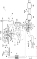
まず、図1及び図2を参照して、本発明の実施形態によるエンジンの失火判定装置が適用されたエンジンシステムについて説明する。図1は、本発明の実施形態によるエンジンの失火判定装置が適用されたエンジンシステムの概略構成図であり、図2は、本発明の実施形態によるエンジンの失火判定装置の電気的構成を示すブロック図である。
<System configuration>
First, an engine system to which an engine misfire determination device according to an embodiment of the present invention is applied will be described with reference to FIGS. 1 and 2. FIG. 1 is a schematic configuration diagram of an engine system to which an engine misfire determination apparatus according to an embodiment of the present invention is applied, and FIG. 2 is a block diagram showing an electrical configuration of the engine misfire determination apparatus according to an embodiment of the present invention. FIG.
図1及び図2に示すように、エンジンシステム100は、主に、外部から導入された吸気(空気)が通過する吸気通路1と、この吸気通路1から供給された吸気と、後述する燃料噴射弁13から供給された燃料との混合気を気筒内で燃焼させて車両の動力を発生するエンジン10(具体的にはガソリンエンジン)と、このエンジン10内の燃焼により発生した排気ガスを排出する排気通路25と、エンジンシステム100に関する各種の状態を検出するセンサ40〜53と、エンジンシステム100全体を制御するPCM60(エンジンの失火判定装置)と、を有する。なお、図1では、1つの気筒のみを示しているが、実際にはエンジン10は複数の気筒(2以上の気筒)を有する。
As shown in FIGS. 1 and 2, the
吸気通路1には、上流側から順に、外部から導入された吸気を浄化するエアクリーナ3と、通過する吸気を昇圧させる、ターボ過給機4のコンプレッサ4aと、外気や冷却水により吸気を冷却するインタークーラ5と、通過する吸気の量(吸入空気量)を調整するスロットルバルブ6と、エンジン10に供給する吸気を一時的に蓄えるサージタンク7と、が設けられている。
In the
また、吸気通路1には、コンプレッサ4aによって過給された吸気の一部を、コンプレッサ4aの上流側に還流するためのエアバイパス通路8が設けられている。具体的には、エアバイパス通路8の一端は、コンプレッサ4aの下流側で且つスロットルバルブ6の上流側の吸気通路1に接続され、エアバイパス通路8の他端は、エアクリーナ3の下流側で且つコンプレッサ4aの上流側の吸気通路1に接続されている。
The
このエアバイパス通路8には、エアバイパス通路8を流れる吸気の流量を開閉動作により調節するエアバイパスバルブ9が設けられている。エアバイパスバルブ9は、エアバイパス通路8を完全に閉じる閉状態と完全に開く開状態とに切り換え可能な、いわゆるオンオフバルブである。
The
エンジン10は、主に、吸気通路1から供給された吸気を燃焼室11内に導入する吸気バルブ12と、燃焼室11に向けて燃料を噴射する燃料噴射弁13と、燃焼室11内に供給された吸気と燃料との混合気に点火する点火プラグ14と、燃焼室11内での混合気の燃焼により往復運動するピストン15と、ピストン15の往復運動により回転されるクランクシャフト16と、燃焼室11内での混合気の燃焼により発生した排気ガスを排気通路25へ排出する排気バルブ17と、を有する。
The
また、エンジン10は、吸気バルブ12及び排気バルブ17のそれぞれの動作タイミング(つまり開閉時期)を、可変バルブタイミング機構(Variable Valve Timing Mechanism)としての可変吸気バルブ機構18及び可変排気バルブ機構19によって可変に構成されている。可変吸気バルブ機構18及び可変排気バルブ機構19としては、公知の種々の形式を適用可能であるが、例えば電磁式又は油圧式に構成された機構を用いて、吸気バルブ12及び排気バルブ17の動作タイミングを変化させることができる。
Further, the
排気通路25には、上流側から順に、通過する排気ガスによって回転され、この回転によってコンプレッサ4aを駆動するターボ過給機4のタービン4bと、例えばNOx触媒や三元触媒や酸化触媒などの、排気ガスの浄化機能を有する触媒装置35a、35bが設けられている。以下では、これらの触媒装置35a、35bを区別しないで用いる場合には単に「触媒装置35」と表記する。
The
また、排気通路25上には、排気ガスの一部をEGRガスとして吸気通路1に還流させるEGR装置26が設けられている。EGR装置26は、一端がタービン4bの上流側の排気通路25に接続され、他端がコンプレッサ4aの下流側で且つスロットルバルブ11の下流側の吸気通路1に接続されたEGR通路27と、EGRガスを冷却するEGRクーラ28と、EGR通路27を流れるEGRガス量(流量)を制御するEGRバルブ29と、を有する。このEGR装置26は、いわゆる高圧EGR装置(HPL(High Pressure Loop)EGR装置)に相当する。
Further, an
また、排気通路25には、排気ガスをターボ過給機4のタービン4bに通過させずに迂回させるタービンバイパス通路30が設けられている。このタービンバイパス通路30には、タービンバイパス通路30を流れる排気ガスの流量を制御するウェイストゲートバルブ(以下「WGバルブ」と称する)31が設けられている。
The
また、排気通路25においては、EGR通路27の上流側の接続部分とタービンバイパス通路30の上流側の接続部分との間の通路が、第1通路25aと第2通路25bとに分岐されている。第1通路25aは第2通路25bよりも径が大きく、換言すると第2通路25bは第1通路25aよりも径が小さく、第1通路25aには開閉バルブ25cが設けられている。開閉バルブ25cが開いている場合には、排気ガスは基本的には第1通路25aに流れ、開閉バルブ25cが閉じている場合には、排気ガスは第2通路25bにのみ流れる。そのため、開閉バルブ25cが閉じている場合には、開閉バルブ25cが開いている場合よりも、排気ガスの流速が大きくなる。開閉バルブ25cは低回転数領域において閉じられ、流速が上昇された排気ガスをターボ過給機4のタービン4bに供給して、低回転域でもターボ過給機4による過給が行えるようになっている。
Further, in the
エンジンシステム100には、当該エンジンシステム100に関する各種の状態を検出するセンサ40〜53が設けられている。これらセンサ40〜53は、具体的には以下の通りである。アクセル開度センサ40は、アクセルペダルの開度(ドライバがアクセルペダルを踏み込んだ量に相当する)であるアクセル開度を検出する。エアフローセンサ41は、エアクリーナ3とコンプレッサ4aとの間の吸気通路1を通過する吸気の流量に相当する吸入空気量を検出する。温度センサ42は、エアクリーナ3とコンプレッサ4aとの間の吸気通路1を通過する吸気の温度を検出する。圧力センサ43は、過給圧を検出する。スロットル開度センサ44は、スロットルバルブ6の開度であるスロットル開度を検出する。温度センサ45は、エンジン10に供給される吸気の温度(吸気温)を検出する。クランク角センサ46は、クランクシャフト16におけるクランク角を検出する。吸気側カム角センサ47は、吸気カムシャフトのカム角を検出する。排気側カム角センサ48は、排気カムシャフトのカム角を検出する。温度センサ49は、エンジン10の冷却水の温度(水温)を検出する。WG開度センサ50は、WGバルブ31の開度を検出する。O2センサ51は、触媒装置35aの上流側の排気ガス中の酸素濃度を検出し、O2センサ52は、触媒装置35aと触媒装置35bとの間の排気ガス中の酸素濃度を検出する。車輪速センサ53は、車輪の速度(車速に相当する)を検出する。これら各種センサ40〜53は、それぞれ、検出したパラメータに対応する検出信号S140〜S153をPCM60に出力する。
The
PCM60は、上述した各種センサ40〜53から入力された検出信号S140〜S153に基づいて、エンジンシステム100内の構成要素に対する制御を行う。具体的には、図2に示すように、PCM60は、スロットルバルブ6に制御信号S106を供給して、スロットルバルブ6の開閉時期やスロットル開度を制御し、エアバイパスバルブ9に制御信号S109を供給して、エアバイパスバルブ9の開閉を制御し、WGバルブ31に制御信号S131を供給して、WGバルブ31の開度を制御し、燃料噴射弁13に制御信号S113を供給して、燃料噴射量や燃料噴射タイミングを制御し、点火プラグ14に制御信号S114を供給して、点火時期を制御し、可変吸気バルブ機構18及び可変排気バルブ機構19のそれぞれに制御信号S118、S119を供給して、吸気バルブ12及び排気バルブ17の動作タイミングを制御し、EGRバルブ29に制御信号S129を供給して、EGRバルブ29の開度を制御する。
The
特に、本実施形態では、PCM60は、クランク角センサ46によって検出されたクランク角に基づき、エンジン10の失火を検出するための失火判定を実行する。また、PCM60は、車輪速センサ53によって検出された車輪速度に基づいて、車輪のスリップを検出するためのスリップ判定を実行する。加えて、PCM60は、エンジン10が失火していると判定された場合に、エンジン10の失火に関連する異常を報知するための警告灯を点灯させる、つまりドライバに異常を報知するためのMIL(Malfunction Indication Lamp)を点灯させる。このように、PCM60は、本発明における「エンジンの失火判定装置」に相当し、本発明における「スリップ判定手段」、「失火判定手段」及び「警告灯点灯手段」として機能する。
In particular, in this embodiment, the
なお、PCM60の各構成要素は、CPU、当該CPU上で解釈実行される各種のプログラム(OSなどの基本制御プログラムや、OS上で起動され特定機能を実現するアプリケーションプログラムを含む)、及びプログラムや各種のデータを記憶するためのROMやRAMの如き内部メモリを備えるコンピュータにより構成される。
Each component of the
<本実施形態による失火判定の概要>
最初に、本発明の実施形態による失火判定の概要について説明する。本実施形態では、PCM60は、クランク角センサ46によって検出されたクランク角に基づきエンジン10の失火を判定する場合において、この失火判定を実行する前に、車輪速の変化量に基づき車輪のスリップを判定し、車輪がスリップしたと判定された場合には失火判定の実行を制限する(つまり禁止する)。こうすることで、車輪のスリップによってドライブシャフトが捩じれてクランク角が大きく変動したときに、このクランク角の変動をエンジン10の失火に起因するものとして判断して、エンジン10の失火を誤判定してしまうことを抑制するようにしている。特に、本実施形態では、PCM60は、車輪のスリップを正確に判定して失火判定の実行/非実行を適切に決定すべく、車輪速の変化量を判定するための判定閾値(以下では「スリップ判定閾値」と呼ぶ。)をエンジン負荷に応じて変化させるようにする。
<Outline of misfire determination according to this embodiment>
First, an outline of misfire determination according to an embodiment of the present invention will be described. In the present embodiment, when the
更に、本実施形態では、PCM60は、クランク角に基づきエンジン10の失火を判定するために用いる判定閾値(以下では「失火判定閾値」と呼ぶ。)を、エンジン10に導入される吸気の吸気密度に基づき変化させるようにする。具体的には、PCM60は、クランク角センサ46の検出信号からクランク角加速度の変動(絶対値)を求めて、このクランク角加速度の変動が失火判定閾値以上である場合に失火が発生したと判定するようにし、この失火判定閾値を吸気密度が高い場合には吸気密度が低い場合よりも大きくして失火判定がなされにくくする。こうすることで、吸気密度が高いことに起因して各気筒に導入される吸気量(充填量)のばらつきが大きくなり、クランク角の変動を大きくなった場合に、このクランク角の変動をエンジン10の失火に起因するものとして判断して、エンジン10の失火を誤判定してしまうことを抑制するようにしている。特に、本実施形態では、PCM60は、エンジン10に導入される吸気の吸気温又は外気温に基づき吸気密度を判断する。この場合、PCM60は、吸気温又は外気温が低い場合には当該温度が高い場合より吸気密度が高いと判断して失火判定閾値を大きくする。
Further, in the present embodiment, the
<スリップ判定>
次に、図3を参照して、本発明の実施形態によるスリップ判定について具体的に説明する。図3では、横軸にエンジン負荷を示し、縦軸に車輪速変化量を示している。図3において、実線のグラフG1は、スリップ判定において車輪速変化量を判定するためのスリップ判定閾値を示している。PCM60は、車輪速変化量がスリップ判定閾値以上である場合には車輪がスリップしたと判定し、車輪速変化量がスリップ判定閾値未満である場合には車輪がスリップしていないと判定する。なお、車輪速変化量は、所定時間における車輪速の変化量(典型的には単位時間当たりの車輪速の変化量)である。
<Slip judgment>
Next, the slip determination according to the embodiment of the present invention will be specifically described with reference to FIG. In FIG. 3, the horizontal axis represents the engine load, and the vertical axis represents the wheel speed change amount. In FIG. 3, a solid line graph G1 shows a slip determination threshold value for determining the wheel speed change amount in the slip determination. The
図3に示すように、スリップ判定閾値は、基本的には、エンジン負荷が高い場合にはエンジン負荷が低い場合よりも大きくなっている。具体的には、スリップ判定閾値は、エンジン負荷が高くなるほど大きくなっている。特に、エンジン負荷の変化に対するスリップ判定閾値の変化率が、エンジン負荷が高くなるほど大きくなっている(つまり二次曲線的に大きくなっている)。例えば、このようなスリップ判定閾値は、実験などにより、スリップが発生したときの車輪速変化量と、スリップが発生していないときの車輪速変化量とを、種々のエンジン負荷について計測することで求められる。
なお、図3において、比較的小さなスリップ判定閾値に設定される低負荷域(符号R11参照)は、ターボ過給機4による過給が行われない非過給域に相当し、この非過給域よりも相対的に大きなスリップ判定閾値に設定される高負荷域(符号R12参照)は、ターボ過給機4による過給が行われる過給域に相当する。
As shown in FIG. 3, the slip determination threshold is basically larger when the engine load is high than when the engine load is low. Specifically, the slip determination threshold increases as the engine load increases. In particular, the rate of change of the slip determination threshold with respect to a change in engine load increases as the engine load increases (that is, increases as a quadratic curve). For example, such a slip determination threshold value is obtained by measuring a change amount of the wheel speed when the slip occurs and a change amount of the wheel speed when the slip does not occur for various engine loads by an experiment or the like. Desired.
In FIG. 3, a low load range (see reference numeral R11) set to a relatively small slip determination threshold corresponds to a non-supercharging range where supercharging by the turbocharger 4 is not performed. A high load range (see reference symbol R12) set to a slip determination threshold value that is relatively larger than the region corresponds to a supercharging region in which supercharging by the turbocharger 4 is performed.
このようにスリップ判定閾値を規定している理由は以下の通りである。通常、エンジン負荷(燃焼トルク)が大きくなると、特に過給域R12のような高負荷域では、車輪速の変化が大きくなる傾向にある。具体的には、高負荷域では、非過給域R11のような低負荷域において車輪がスリップしたときよりも、車輪速の変化が大きくなる傾向にある(当然、高負荷域で車輪がスリップしたときには車輪速の変化が更に大きくなる)。したがって、本実施形態では、低負荷域でのスリップ判定の精度を確保しつつ、高負荷域でのスリップの誤判定を抑制するように、エンジン負荷が高くなるほどスリップ判定閾値を大きくしている、換言するとエンジン負荷が低くなるほどスリップ判定閾値を小さくしている。これにより、失火の誤判定を抑制するようにスリップ発生時に失火判定を制限する構成において、適切なスリップ判定閾値を用いてスリップの誤判定を抑制することによって、スリップが発生していないにも関わらずに失火判定を無駄に制限してしまうことを抑制して、失火判定の実行頻度を確保するようにしている。 The reason why the slip determination threshold is defined in this way is as follows. Normally, when the engine load (combustion torque) increases, the wheel speed tends to increase, particularly in a high load region such as the supercharging region R12. Specifically, in the high load region, the wheel speed tends to change more than when the wheel slips in a low load region such as the non-supercharging region R11 (naturally, the wheel slips in the high load region). When this happens, the change in wheel speed becomes even greater). Therefore, in the present embodiment, the slip determination threshold is increased as the engine load increases so as to suppress the erroneous determination of the slip in the high load region while ensuring the accuracy of the slip determination in the low load region. In other words, the slip determination threshold is made smaller as the engine load becomes lower. As a result, in the configuration in which misfire determination is limited at the time of occurrence of slip so as to suppress misjudgment of misfire, the slip misjudgment is suppressed by using an appropriate slip determination threshold, so that no slip has occurred. Therefore, it is possible to prevent the misfire determination from being limited unnecessarily, and to ensure the frequency of execution of the misfire determination.
<外気温に応じた失火判定>
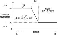
次に、図4を参照して、本発明の実施形態における、吸気密度に関連する外気温を考慮に入れた失火判定について具体的に説明する。図4は、横軸に外気温を示し、縦軸にクランク角加速度の変動(絶対値)を示している。図4において、実線のグラフG2は、失火判定においてクランク角加速度の変動を判定するための失火判定閾値を示している。PCM60は、クランク角加速度の変動が失火判定閾値以上である場合にはエンジン10の失火が発生したと判定し、クランク角加速度の変動が失火判定閾値未満である場合にはエンジン10の失火が発生してないと判定する。なお、クランク角加速度の変動は、所定時間におけるクランク角加速度の変化量の大きさである。
<Failure judgment according to outside temperature>
Next, with reference to FIG. 4, the misfire determination in the embodiment of the present invention taking into account the outside air temperature related to the intake air density will be specifically described. FIG. 4 shows the outside air temperature on the horizontal axis and the fluctuation (absolute value) of the crank angular acceleration on the vertical axis. In FIG. 4, a solid line graph G2 indicates a misfire determination threshold value for determining a variation in crank angular acceleration in the misfire determination. The
図4に示すように、失火判定閾値は、外気温が低い場合(例えば0℃未満)には外気温が高い場合(例えば20℃以上)よりも大きくなっている。具体的には、外気温が所定範囲R2(例えば0℃から20℃までの範囲)を下回る領域では、符号A1で示す失火判定閾値に設定され、外気温が所定範囲R2を上回る領域では、上記の失火判定閾値A1よりも小さな、符号A2で示す失火判定閾値に設定され、外気温が所定範囲R2内にある場合には、外気温の大きさに応じて、上記の失火判定閾値A1と失火判定閾値A2との間の値に設定されるようになっている。つまり、外気温が所定範囲R2内にある場合には、外気温に応じてA1とA2との間で失火判定閾値が変化するようになっている。例えば、このような失火判定閾値は、実験やシミュレーションなどにより、失火の発生時及び未発生時のそれぞれにおけるクランク角加速度変動を、種々の外気温について計測することで求められる。
なお、失火判定閾値は、基本的にはエンジン回転数及びエンジン負荷に基づいて設定され、図4では、或るエンジン回転数及びエンジン負荷において適用される、外気温に応じた失火判定閾値の一例を示している。
As shown in FIG. 4, the misfire determination threshold is larger when the outside air temperature is low (for example, less than 0 ° C.) than when the outside air temperature is high (for example, 20 ° C. or more). Specifically, in a region where the outside air temperature is below a predetermined range R2 (for example, a range from 0 ° C. to 20 ° C.), the misfire determination threshold indicated by reference numeral A1 is set, and in a region where the outside air temperature exceeds the predetermined range R2, When the outside air temperature is within the predetermined range R2, which is smaller than the misfire judgment threshold A1, the misfire judgment threshold A1 and the misfire are set according to the magnitude of the outside air temperature. It is set to a value between the determination threshold A2. That is, when the outside air temperature is within the predetermined range R2, the misfire determination threshold value changes between A1 and A2 according to the outside air temperature. For example, such a misfire determination threshold value can be obtained by measuring crank angular acceleration fluctuations at the time of misfire occurrence and at the time of non-fire occurrence with respect to various outside air temperatures through experiments or simulations.
Note that the misfire determination threshold value is basically set based on the engine speed and the engine load. In FIG. 4, an example of the misfire determination threshold value according to the outside air temperature applied at a certain engine speed and engine load. Is shown.
このように失火判定閾値を規定している理由は以下の通りである。インテークマニホールドの形状や気筒への吸気の流れやすさ(換言すると吸気の流れにくさ)などにより、各気筒に導入される吸気量(充填量)が気筒ごとに僅かに異なる。外気温が低くなると吸気密度が高くなるので、そのような各気筒に導入される吸気量のばらつきが大きくなる。そのため、各気筒での燃焼ばらつきが大きくなり、クランク角が大きく変動する傾向にある。したがって、本実施形態では、このような吸気密度が高いときに発生するクランク角の変動をエンジン10の失火と誤判定してしまうことを抑制すべく、外気温が低い場合には外気温が高い場合よりも失火判定閾値を大きくする。こうすることで、吸気密度が低い場合(つまり外気温が高い場合)における失火判定の精度を確保しつつ、吸気密度が高い場合(つまり外気温が低い場合)における失火の誤判定を抑制するようにしている。 The reason why the misfire determination threshold is defined in this way is as follows. Depending on the shape of the intake manifold and the ease of intake air flow into the cylinders (in other words, the difficulty of intake air flow), the intake air amount (filling amount) introduced into each cylinder varies slightly from cylinder to cylinder. Since the intake air density increases as the outside air temperature decreases, the variation in the intake air amount introduced into each cylinder increases. Therefore, the combustion variation in each cylinder increases, and the crank angle tends to fluctuate greatly. Therefore, in the present embodiment, when the outside air temperature is low, the outside air temperature is high so as to prevent the crank angle variation that occurs when the intake air density is high from being erroneously determined as misfire of the engine 10. Make the misfire determination threshold larger than the case. By doing this, while ensuring the accuracy of misfire determination when the intake air density is low (that is, when the outside air temperature is high), misjudgment of misfire when the intake air density is high (that is, when the outside air temperature is low) is suppressed. I have to.
なお、上記では、外気温に基づき失火判定閾値を設定する例を示したが、外気温の代わりに吸気温に基づき失火判定閾値を設定してもよい。その場合にも、図4と同様に、吸気温に応じた失火判定閾値が規定される。本実施形態におけるエンジン10には、ターボ過給機4によって過給された吸気が供給されるので、ターボ過給機4によって過給されてインタークーラ5を通過した後の吸気の温度(温度センサ45によって検出された温度)を用いて失火判定閾値を設定するとよい。
In the above description, the misfire determination threshold value is set based on the outside air temperature. However, the misfire determination threshold value may be set based on the intake air temperature instead of the outside air temperature. Also in that case, the misfire determination threshold value corresponding to the intake air temperature is defined as in FIG. Since the
<失火判定処理>
次に、図5を参照して、本発明の実施形態による失火判定の具体的な処理について説明する。図5は、本発明の実施形態による失火判定処理を示すフローチャートである。この失火判定処理は、PCM60によって所定の周期で繰り返し実行される。
<Misfire detection process>
Next, with reference to FIG. 5, the specific process of misfire determination by embodiment of this invention is demonstrated. FIG. 5 is a flowchart showing misfire determination processing according to the embodiment of the present invention. This misfire determination process is repeatedly executed by the
まず、ステップS101では、PCM60は、車両における各種情報を取得する。特に、PCM60は、温度センサ45によって検出された吸気温や、クランク角センサ46によって検出されたクランク角や、車輪速センサ53によって検出された車輪速などを取得する。
First, in step S101, the
次いで、ステップS102では、PCM60は、失火判定条件が成立しているか否かを判定する。具体的には、PCM60は、変速が行われておらず、燃料カットが行われておらず、且つ、エンジン水温が所定温度以上であり、尚且つ、エンジン回転数が所定回転数以上である場合に、失火判定条件が成立していると判定し(ステップS102:Yes)、ステップS103に進む。一方で、PCM60は、変速が行われた場合、燃料カットが行われた場合、エンジン水温が所定温度未満である場合、又は、エンジン回転数が所定回転数未満である場合には、失火判定条件が成立していないと判定する(ステップS102:No)。この場合には、PCM60は、失火判定を実行せずに、失火判定処理のフローを抜ける。
Next, in step S102, the
ステップS103では、PCM60は、エンジン負荷に基づきスリップ判定閾値を設定する。具体的には、PCM60は、図3に示したスリップ判定閾値のマップに基づき、現在のエンジン負荷に対応するスリップ判定閾値を設定する。
In step S103, the
次いで、ステップS104では、PCM60は、車輪速センサ53によって検出された車輪速から車輪速変化量を求め、この車輪速変化量とステップS103で設定したスリップ判定閾値とを比較することで車輪のスリップが発生していないか否かを判定する。PCM60は、車輪速変化量がスリップ判定閾値未満である場合にはスリップが発生していないと判定し(ステップS104:Yes)、ステップS105に進む。ステップS105以降では、PCM60は、失火判定を実際に実行するための処理を行う。一方、PCM60は、車輪速変化量がスリップ判定閾値以上である場合にはスリップが発生したと判定する(ステップS104:No)。この場合には、PCM60は、失火判定を実行せずに、失火判定処理のフローを抜ける。
Next, in step S104, the
ステップS105では、PCM60は、失火判定閾値を設定するために用いる常温用失火リファレンス、低温用失火リファレンス及びリファレンス配分を設定する。これらの常温用失火リファレンス、低温用失火リファレンス及びリファレンス配分は、エンジン回転数、エンジン負荷及び外気温に応じた失火判定閾値を設定するために用いられる。具体的には、常温用失火リファレンスは、外気温が常温(例えば25℃)であるときに、エンジン回転数及びエンジン負荷に応じて適用すべき失火判定閾値に相当し、低温用失火リファレンスは、外気温が低温(例えば氷点下の温度)であるときに、エンジン回転数及びエンジン負荷に応じて適用すべき失火判定閾値に相当する。また、リファレンス配分は、最終的に適用する失火判定閾値を決定するに当たって、上記の常温用失火リファレンス及び低温用失火リファレンスを外気温に応じて配分する比率に相当する。このリファレンス配分に応じて常温用失火リファレンス及び低温用失火リファレンスを加算することで、最終的に適用する失火判定閾値が決定される。
In step S105, the
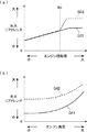
ここで、図6及び図7を参照して、常温用失火リファレンス、低温用失火リファレンス及びリファレンス配分を設定する方法について具体的に説明する。図6は、本発明の実施形態による常温用失火リファレンス及び低温用失火リファレンスを示しており、図7は、本発明の実施形態によるリファレンス配分を示している。 Here, with reference to FIG.6 and FIG.7, the method of setting the misfire reference for normal temperature, the misfire reference for low temperature, and reference distribution is demonstrated concretely. FIG. 6 illustrates a misfire reference for normal temperature and a misfire reference for low temperature according to an embodiment of the present invention, and FIG. 7 illustrates reference distribution according to an embodiment of the present invention.
図6(a)は、同一のエンジン負荷で見たときのエンジン回転数(横軸)と失火リファレンス(縦軸)との関係を示すグラフである。図6(a)において、実線のグラフG31は常温用失火リファレンスを示し、破線のグラフG32は低温用失火リファレンスを示している。図6(a)に示すように、基本的には、常温用失火リファレンス及び低温用失火リファレンスの両方とも、同一のエンジン負荷で見たときにエンジン回転数が高くなるほど大きな値になっている。 FIG. 6A is a graph showing the relationship between the engine speed (horizontal axis) and the misfire reference (vertical axis) when viewed at the same engine load. In FIG. 6A, a solid line graph G31 indicates a normal temperature misfire reference, and a broken line graph G32 indicates a low temperature misfire reference. As shown in FIG. 6 (a), both the room temperature misfire reference and the low temperature misfire reference basically have larger values as the engine speed increases when viewed at the same engine load.
特に、本実施形態では、エンジン回転数N1を超える領域において、常温用失火リファレンスと低温用失火リファレンスとの値を異ならせている。具体的には、エンジン回転数N1を超えると、エンジン回転数の増加に応じた失火リファレンスの上昇量を、常温用失火リファレンスよりも低温用失火リファレンスのほうを大きくしている。こうしているのは、低外気温の状況下において高回転域になると、各気筒に導入される吸気量のばらつきに起因するクランク角の変動が大きくなるからである(換言すると、低外気温の状況下でも低回転域ではクランク角の変動が小さくなる)。したがって、本実施形態では、このような低外気温の状況下での高回転域において発生する比較的大きなクランク角の変動を失火と誤判定することを抑制すべく、エンジン回転数N1を超える領域において、常温用失火リファレンスよりも低温用失火リファレンスを大きくしている。 Particularly, in the present embodiment, the values of the misfire reference for normal temperature and the misfire reference for low temperature are made different in a region exceeding the engine speed N1. Specifically, when the engine speed N1 is exceeded, the amount of increase in the misfire reference corresponding to the increase in the engine speed is made larger for the low temperature misfire reference than for the room temperature misfire reference. This is because when the engine is in the high rotation range under low outside air temperature conditions, the fluctuation of the crank angle due to the variation in the intake air amount introduced into each cylinder increases (in other words, the low outside air temperature situation). Even under, the fluctuation of the crank angle becomes smaller in the low rotation range). Therefore, in the present embodiment, in order to suppress misjudgment of misalignment as a relatively large variation in the crank angle that occurs in the high engine speed range under such low outside air temperature conditions, a region that exceeds the engine speed N1. , The misfire reference for low temperature is made larger than the misfire reference for room temperature.
図6(b)は、上記したエンジン回転数N1を超える同一のエンジン回転数で見たときの、エンジン負荷(横軸)と失火リファレンス(縦軸)との関係を示すグラフである。図6(b)において、実線のグラフG41は常温用失火リファレンスを示し、破線のグラフG42は低温用失火リファレンスを示している。図6(b)に示すように、基本的には、常温用失火リファレンス及び低温用失火リファレンスの両方とも、同一のエンジン回転数で見たときにエンジン負荷が高くなるほど大きな値になっている。特に、本実施形態では、エンジン回転数N1を超える高回転域では、エンジン負荷のほぼ全域に渡って、常温用失火リファレンスよりも低温用失火リファレンスを大きくしている。これは、上記したように低外気温の状況下での高回転域においてはクランク角の変動が大きくなるため、このクランク角の変動を失火と誤判定することを確実に抑制するようにしたものである。 FIG. 6B is a graph showing the relationship between the engine load (horizontal axis) and the misfire reference (vertical axis) when viewed at the same engine speed exceeding the engine speed N1 described above. In FIG. 6B, a solid line graph G41 indicates a normal temperature misfire reference, and a broken line graph G42 indicates a low temperature misfire reference. As shown in FIG. 6B, basically, both the misfire reference for normal temperature and the misfire reference for low temperature have larger values as the engine load increases when viewed at the same engine speed. In particular, in the present embodiment, in the high engine speed range exceeding the engine speed N1, the low temperature misfire reference is made larger than the room temperature misfire reference over almost the entire engine load. This is because, as described above, the crank angle fluctuates greatly in the high rotation range under the condition of low outside air temperature, so that the misjudgment of misalignment of the crank angle as misfire is surely suppressed. It is.
なお、図6(b)に示していないエンジン回転数N1を下回る領域では、エンジン負荷と失火リファレンスとの関係は常温用失火リファレンスと低温用失火リファレンスとで同じである(つまりエンジン負荷に応じて同じ値が設定される)。また、エンジン回転数N1を下回る領域でも、基本的には、常温用失火リファレンス及び低温用失火リファレンスの両方とも、エンジン負荷が高くなるほど大きな値に設定されるようになっている。
また、図6(a)及び(b)に示した常温用失火リファレンスは、実験やシミュレーションなどにより、常温(例えば25℃)において、失火の発生時及び未発生時のそれぞれにおけるクランク角加速度変動を、種々のエンジン回転数及びエンジン負荷について計測することで求められる。同様に、低温用失火リファレンスは、実験やシミュレーションなどにより、低温(例えば氷点下の温度)において、失火の発生時及び未発生時のそれぞれにおけるクランク角加速度変動を、種々のエンジン回転数及びエンジン負荷について計測することで求められる。
In the region below the engine speed N1, which is not shown in FIG. 6B, the relationship between the engine load and the misfire reference is the same between the room temperature misfire reference and the low temperature misfire reference (that is, depending on the engine load). The same value is set). Further, even in a region below the engine speed N1, both the normal temperature misfire reference and the low temperature misfire reference are basically set to larger values as the engine load increases.
In addition, the misfire reference for room temperature shown in FIGS. 6 (a) and 6 (b) shows the variation in crank angular acceleration when misfire occurs and when it does not occur at room temperature (for example, 25 ° C.) through experiments and simulations. It is obtained by measuring various engine speeds and engine loads. Similarly, the misfire reference for low temperature is based on experiments and simulations, and the crank angular acceleration fluctuations at the time of misfire occurrence and at non-occurrence at low temperatures (for example, temperatures below freezing point) for various engine speeds and engine loads. It is calculated by measuring.
図7は、外気温(横軸)とリファレンス配分(縦軸)との関係を示すグラフである。リファレンス配分は、常温用失火リファレンスに対する低温用失火リファレンスの比率を示している。例えば、リファレンス配分が「1」である場合には、低温用失火リファレンスの配分が「1」で、常温用失火リファレンスの配分が「0」であり、この場合には最終的に適用する失火判定閾値が低温用失火リファレンスとなる。他方で、リファレンス配分が「0」である場合には、低温用失火リファレンスの配分が「0」で、常温用失火リファレンスの配分が「1」であり、この場合には最終的に適用する失火判定閾値が常温用失火リファレンスとなる。 FIG. 7 is a graph showing the relationship between the outside air temperature (horizontal axis) and the reference distribution (vertical axis). The reference distribution shows the ratio of the low temperature misfire reference to the room temperature misfire reference. For example, when the reference distribution is “1”, the low-temperature misfire reference distribution is “1” and the normal-temperature misfire reference distribution is “0”. The threshold is a low temperature misfire reference. On the other hand, when the reference distribution is “0”, the low temperature misfire reference distribution is “0” and the normal temperature misfire reference distribution is “1”. In this case, the misfire to be finally applied is The determination threshold is a room temperature misfire reference.
図7に示すように、リファレンス配分は、外気温が低い場合(例えば0℃未満)には外気温が高い場合(例えば20℃以上)よりも大きくなっている。具体的には、リファレンス配分は外気温が所定範囲R3(例えば0℃から20℃までの範囲)を下回る領域では「1」に設定され、外気温が所定範囲R3を上回る領域では「0」に設定され、外気温が所定範囲R3内にある場合には、外気温の大きさに応じた「0」と「1」との間の値に設定されるようになっている。つまり、外気温が所定範囲R2内にある場合には、外気温に応じて「0」と「1」との間でリファレンス配分が変化するようになっている。 As shown in FIG. 7, the reference distribution is larger when the outside air temperature is low (for example, less than 0 ° C.) than when the outside air temperature is high (for example, 20 ° C. or more). Specifically, the reference distribution is set to “1” when the outside air temperature is below a predetermined range R3 (for example, a range from 0 ° C. to 20 ° C.), and is set to “0” when the outside air temperature exceeds the predetermined range R3. When the outside air temperature is within the predetermined range R3, the value is set to a value between “0” and “1” corresponding to the magnitude of the outside air temperature. That is, when the outside air temperature is within the predetermined range R2, the reference distribution changes between “0” and “1” according to the outside air temperature.
なお、このようなリファレンス配分を規定する外気温の領域は、図4に示した失火判定閾値を規定する外気温の領域に対応するものである。因みに、図4は、エンジン回転数N1を超える所定のエンジン回転数及び所定のエンジン負荷に応じて設定された常温用失火リファレンス及び低温用失火リファレンスより求められた、外気温と失火判定閾値との関係の一例を示したものである。 It should be noted that the outside air temperature region that defines the reference distribution corresponds to the outside air temperature region that defines the misfire determination threshold shown in FIG. Incidentally, FIG. 4 shows the relationship between the outside air temperature and the misfire determination threshold value obtained from the normal temperature misfire reference and the low temperature misfire reference set according to the predetermined engine speed exceeding the engine speed N1 and the predetermined engine load. An example of the relationship is shown.
次に、図5に戻って、ステップS105の説明を再開する。ステップS105では、PCM60は、現在のエンジン回転数及びエンジン負荷に対応する常温用失火リファレンス及び低温用失火リファレンスをそれぞれ決定すると共に(図6参照)、現在の外気温に対応するリファレンス配分を決定する(図7参照)。この場合、PCM60は、温度センサ45によって検出された吸気温に基づき推定した外気温、若しくは、外気温センサを車両に設けて、この外気温センサによって検出された外気温を用いて、リファレンス配分を決定する。なお、外気温の代わりに吸気温に基づいてリファレンス配分を規定してもよい。その場合には、温度センサ45によって検出された吸気温に基づきリファレンス配分を決定すればよい。
Next, returning to FIG. 5, the description of step S105 is resumed. In step S105, the
次いで、ステップS106では、PCM60は、ステップS105で設定した常温用失火リファレンス、低温用失火リファレンス及びリファレンス配分に基づいて、失火判定閾値を設定する。具体的には、PCM60は、リファレンス配分に応じて常温用失火リファレンス及び低温用失火リファレンスを加算することで失火判定閾値を求める。
Next, in step S106, the
次いで、ステップS107では、PCM60は、クランク角センサ46によって検出されたクランク角に基づき、クランク角加速度変動(絶対値)を算出する。具体的には、PCM60は、クランク角センサ46によって計測した周期からクランク角加速度を繰り返し求めてサンプリングし、サンプリングしたクランク角加速度をフィルタ処理(ハイパスフィルタなど)してから、所定時間におけるクランク角加速度の変化量をクランク角加速度変動として求める。
Next, in step S107, the
次いで、ステップS108では、PCM60は、ステップS107で求めたクランク角加速度変動がステップS106で設定した失火判定閾値以上であるか否かを判定する。当該判定は、失火による大きな減速度に対応するクランク角の変動が発生したか否かを判定していることに相当する。
Next, in step S108, the
クランク角加速度変動が失火判定閾値以上である場合(ステップS108:Yes)、PCM60は、ステップS109に進み、エンジン10の失火が発生したと判定する。この場合、PCM60は、複数の気筒のうちで失火が発生した気筒も特定する。一方で、クランク角加速度変動が失火判定閾値未満である場合(ステップS108:No)、PCM60は、失火判定処理のフローを抜ける。この場合には、PCM60は、エンジン10の失火が発生していないと判定する。
If the crank angular acceleration fluctuation is greater than or equal to the misfire determination threshold (step S108: Yes), the
ステップS109の後、ステップS110に進み、PCM60は、エンジン10の失火に関連する異常を報知するための警告灯を点灯させる条件(警告灯点灯条件)が成立したか否かを判定する。具体的には、PCM60は、触媒装置35を保護するために点灯させる警告灯(以下では「触媒警告灯」と呼ぶ。)と、エミッションの悪化を報知するために点灯させる警告灯(以下では「エミッション警告灯」と呼ぶ。)のそれぞれについて、警告灯点灯条件が成立したか否かを判定する。触媒警告灯についての警告灯点灯条件は、エンジン10の回転回数(燃焼回数に相当する)が第1所定値に達したときに、それまでに失火が発生した回数が第2所定値以上であるという条件である。この第2所定値は、エンジン回転数や吸入空気量に応じて変化させるのがよい。他方で、エミッション警告灯についての警告灯点灯条件は、エンジン10の回転回数(燃焼回数に相当する)が第3所定値(>第1所定値)に達したときに、それまでに失火が発生した回数が第4所定値以上であるという条件である。
After step S109, the process proceeds to step S110, and the
ステップS110の判定の結果、触媒警告灯についての警告灯点灯条件、又はエミッション警告灯についての警告灯点灯条件が成立したと判定された場合(ステップS110:Yes)、ステップS111に進み、PCM60は、触媒警告灯又はエミッション警告灯を点灯させる。一方で、触媒警告灯についての警告灯点灯条件、又はエミッション警告灯についての警告灯点灯条件が成立したと判定されなかった場合(ステップS110:No)、PCM60は、失火判定処理のフローを抜ける。この場合には、PCM60は、触媒警告灯及びエミッション警告灯を点灯させない。
As a result of the determination in step S110, when it is determined that the warning lamp lighting condition for the catalyst warning lamp or the warning lamp lighting condition for the emission warning lamp is satisfied (step S110: Yes), the process proceeds to step S111, and the
<作用効果>
次に、本発明の実施形態によるエンジンの失火判定装置の作用効果について説明する。
<Effect>
Next, the effect of the engine misfire determination device according to the embodiment of the present invention will be described.
本実施形態によれば、車輪がスリップしたと判定された場合に失火判定の実行を制限する(禁止する)ので、車輪のスリップによってドライブシャフトが捩じれてクランク角が大きく変動したときに、このクランク角の変動をエンジン10の失火に起因するものとして判断して、エンジン10の失火を誤判定してしまうことを適切に抑制することができる。特に、本実施形態によれば、スリップ判定において車輪速変化量を判定するために用いるスリップ判定閾値を、エンジン負荷が高い場合にはエンジン負荷が低い場合よりも大きくするので(換言するとエンジン負荷が低い場合にはエンジン負荷が高い場合よりも小さくするので)、エンジン負荷が高くなるとスリップしていなくても車輪速変化量が大きくなるという特性を考慮して、スリップ判定閾値を設定することができる。これにより、低負荷域でのスリップ判定の精度を確保しつつ、高負荷域でのスリップの誤判定を抑制することができる。したがって、失火の誤判定を抑制するようにスリップ発生時に失火判定を制限する構成において、適切なスリップ判定閾値を用いてスリップの誤判定を抑制することによって、スリップが発生していないにも関わらずに失火判定を無駄に制限してしまうことを抑制して、失火判定の実行頻度を確保することができる。
According to this embodiment, when it is determined that the wheel has slipped, execution of misfire determination is restricted (prohibited). Therefore, when the drive shaft is twisted due to wheel slip and the crank angle greatly fluctuates, It is possible to appropriately suppress the misjudgment of misfire of the
また、本実施形態によれば、スリップ判定閾値をエンジン負荷が高くなるほど大きくするので、スリップ時の車輪速変化量に加えて、エンジン負荷に対する車輪速変化量の実際の特性を適切に考慮に入れたスリップ判定閾値を設定することができる。よって、スリップ判定精度の確保とスリップの誤判定の抑制とを効果的に両立することができる。特に、本実施形態によれば、エンジン負荷の変化に対するスリップ判定閾値の変化率を、エンジン負荷が高くなるほど大きくするので、エンジン負荷に対する車輪速変化量の実際の特性をより正確に考慮に入れたスリップ判定閾値を設定することができる。 In addition, according to the present embodiment, the slip determination threshold value is increased as the engine load increases, so that the actual characteristics of the wheel speed change amount with respect to the engine load are appropriately taken into account in addition to the wheel speed change amount during the slip. A slip determination threshold value can be set. Therefore, it is possible to effectively achieve both the slip determination accuracy and the suppression of slip slip determination. In particular, according to the present embodiment, the rate of change of the slip determination threshold with respect to changes in the engine load is increased as the engine load increases, so the actual characteristics of the wheel speed change amount with respect to the engine load are taken into account more accurately. A slip determination threshold can be set.
また、本実施形態によれば、ターボ過給機4を備えるエンジンシステム100において、過給域R12では非過給域R11よりもスリップ判定閾値を大きくするので、エンジン負荷が高くなって車輪速変化量が大きくなる過給域R12において適切なスリップ判定閾値を設定することができる。
Further, according to the present embodiment, in the
また、本実施形態によれば、エンジン10が失火していると判定された場合に警告灯を点灯させるので、失火に関連する異常をドライバに適切に報知することができる。
In addition, according to the present embodiment, the warning light is turned on when it is determined that the
<変形例>
上記した実施形態では、クランク角加速度変動に基づいて失火判定を行っていたが、他の例では、クランク角自体の変動、クランク角速度の変動、若しくはクランク角加速度の大きさに基づいて、失火判定を行ってもよい。
<Modification>
In the above-described embodiment, the misfire determination is performed based on the crank angular acceleration variation, but in other examples, the misfire determination is performed based on the variation of the crank angle itself, the variation of the crank angular velocity, or the magnitude of the crank angular acceleration. May be performed.
上記した実施形態では、本発明をガソリンエンジンに適用した例を示したが、本発明はディーゼルエンジンに適用してもよい。また、上記した実施形態では、本発明を過給機付きエンジンに適用した例を示したが、本発明は過給機付きエンジンへの適用に限定はされない。 In the above-described embodiment, an example in which the present invention is applied to a gasoline engine has been described. However, the present invention may be applied to a diesel engine. In the above-described embodiment, an example in which the present invention is applied to an engine with a supercharger has been shown, but the present invention is not limited to application to an engine with a supercharger.
1 吸気通路
4 ターボ過給機
6 スロットルバルブ
10 エンジン
11 燃焼室
12 吸気バルブ
13 燃料噴射弁
14 点火プラグ
15 ピストン
17 排気バルブ
25 排気通路
26 EGR装置
35a、35b 触媒装置
60 PCM
100 エンジンシステム
DESCRIPTION OF
100 engine system
Claims (7)
車両の車輪速の変化量が所定の判定閾値以上である場合に、車輪がスリップしたと判定するスリップ判定手段と、
エンジンの失火判定を実行する失火判定手段であって、この失火判定手段は、上記スリップ判定手段によって車輪がスリップしたと判定された場合に上記失火判定の実行を制限する、上記失火判定手段と、を有し、
上記スリップ判定手段は、エンジン負荷が高い場合にはエンジン負荷が低い場合よりも上記判定閾値を大きくする、ことを特徴とするエンジンの失火判定装置。 In the engine misfire determination device for determining engine misfire,
Slip determination means for determining that the wheel has slipped when the amount of change in wheel speed of the vehicle is equal to or greater than a predetermined determination threshold;
Misfire determination means for performing engine misfire determination, wherein the misfire determination means limits execution of the misfire determination when the slip determination means determines that a wheel has slipped; and Have
The engine misfire determination apparatus according to claim 1, wherein the slip determination means increases the determination threshold when the engine load is high than when the engine load is low.
車両の車輪速の変化量が所定の判定閾値以上である場合に、車輪がスリップしたと判定するスリップ判定手段と、
エンジンの失火判定を実行する失火判定手段であって、この失火判定手段は、上記スリップ判定手段によって車輪がスリップしたと判定された場合に上記失火判定の実行を制限する、上記失火判定手段と、を有し、
上記スリップ判定手段は、過給機による過給が行われる過給域では、過給機による過給が行われない非過給域よりも、上記判定閾値を大きくする、ことを特徴とするエンジンの失火判定装置。 In an engine misfire determination device that is applied to an engine with a supercharger and determines misfire of this engine,
Slip determination means for determining that the wheel has slipped when the amount of change in wheel speed of the vehicle is equal to or greater than a predetermined determination threshold;
Misfire determination means for performing engine misfire determination, wherein the misfire determination means limits execution of the misfire determination when the slip determination means determines that a wheel has slipped; and Have
The engine according to claim 1, wherein the slip determination means increases the determination threshold in a supercharging region where supercharging by a supercharger is performed, compared to a non-supercharging region where supercharging by a supercharger is not performed. Misfire detection device.
Priority Applications (2)
| Application Number | Priority Date | Filing Date | Title |
|---|---|---|---|
| JP2016058512A JP6694302B2 (en) | 2016-03-23 | 2016-03-23 | Engine misfire determination device |
| US15/464,045 US20170276084A1 (en) | 2016-03-23 | 2017-03-20 | Misfire detecting system for engine |
Applications Claiming Priority (1)
| Application Number | Priority Date | Filing Date | Title |
|---|---|---|---|
| JP2016058512A JP6694302B2 (en) | 2016-03-23 | 2016-03-23 | Engine misfire determination device |
Publications (2)
| Publication Number | Publication Date |
|---|---|
| JP2017172433A true JP2017172433A (en) | 2017-09-28 |
| JP6694302B2 JP6694302B2 (en) | 2020-05-13 |
Family
ID=59896411
Family Applications (1)
| Application Number | Title | Priority Date | Filing Date |
|---|---|---|---|
| JP2016058512A Active JP6694302B2 (en) | 2016-03-23 | 2016-03-23 | Engine misfire determination device |
Country Status (2)
| Country | Link |
|---|---|
| US (1) | US20170276084A1 (en) |
| JP (1) | JP6694302B2 (en) |
Cited By (2)
| Publication number | Priority date | Publication date | Assignee | Title |
|---|---|---|---|---|
| WO2019049490A1 (en) | 2017-09-07 | 2019-03-14 | 住友建機株式会社 | Excavator |
| CN110397511A (en) * | 2019-07-01 | 2019-11-01 | 中国第一汽车股份有限公司 | A kind of fault handling method and system |
Families Citing this family (2)
| Publication number | Priority date | Publication date | Assignee | Title |
|---|---|---|---|---|
| JP6395116B2 (en) * | 2016-03-23 | 2018-09-26 | マツダ株式会社 | Engine misfire determination device |
| JP6407396B1 (en) * | 2017-12-07 | 2018-10-17 | 三菱電機株式会社 | Control device and control method for internal combustion engine |
Citations (9)
| Publication number | Priority date | Publication date | Assignee | Title |
|---|---|---|---|---|
| JPH05272399A (en) * | 1992-03-25 | 1993-10-19 | Nippondenso Co Ltd | Misfire detecting device for multi-cylinder internal combustion engine for vehicle |
| JPH06108890A (en) * | 1992-09-29 | 1994-04-19 | Mazda Motor Corp | Traction control device |
| JPH07217468A (en) * | 1994-02-04 | 1995-08-15 | Unisia Jecs Corp | Misfire diagnostic device for vehicle |
| JPH116450A (en) * | 1997-06-18 | 1999-01-12 | Nissan Motor Co Ltd | Vehicle driving force control device |
| JP2000027675A (en) * | 1998-07-15 | 2000-01-25 | Nissan Motor Co Ltd | Traction control method and device therefor |
| JP2000248989A (en) * | 1999-02-25 | 2000-09-12 | Fuji Heavy Ind Ltd | Misfire detecting device for multi-cylinder engine |
| JP2004090869A (en) * | 2002-09-03 | 2004-03-25 | Advics:Kk | Traveling obstacle preventative device of vehicle |
| JP2006115644A (en) * | 2004-10-15 | 2006-04-27 | Nissan Motor Co Ltd | Motor traction controller of vehicle |
| WO2013014789A1 (en) * | 2011-07-28 | 2013-01-31 | トヨタ自動車株式会社 | Internal combustion engine control apparatus |
-
2016
- 2016-03-23 JP JP2016058512A patent/JP6694302B2/en active Active
-
2017
- 2017-03-20 US US15/464,045 patent/US20170276084A1/en not_active Abandoned
Patent Citations (9)
| Publication number | Priority date | Publication date | Assignee | Title |
|---|---|---|---|---|
| JPH05272399A (en) * | 1992-03-25 | 1993-10-19 | Nippondenso Co Ltd | Misfire detecting device for multi-cylinder internal combustion engine for vehicle |
| JPH06108890A (en) * | 1992-09-29 | 1994-04-19 | Mazda Motor Corp | Traction control device |
| JPH07217468A (en) * | 1994-02-04 | 1995-08-15 | Unisia Jecs Corp | Misfire diagnostic device for vehicle |
| JPH116450A (en) * | 1997-06-18 | 1999-01-12 | Nissan Motor Co Ltd | Vehicle driving force control device |
| JP2000027675A (en) * | 1998-07-15 | 2000-01-25 | Nissan Motor Co Ltd | Traction control method and device therefor |
| JP2000248989A (en) * | 1999-02-25 | 2000-09-12 | Fuji Heavy Ind Ltd | Misfire detecting device for multi-cylinder engine |
| JP2004090869A (en) * | 2002-09-03 | 2004-03-25 | Advics:Kk | Traveling obstacle preventative device of vehicle |
| JP2006115644A (en) * | 2004-10-15 | 2006-04-27 | Nissan Motor Co Ltd | Motor traction controller of vehicle |
| WO2013014789A1 (en) * | 2011-07-28 | 2013-01-31 | トヨタ自動車株式会社 | Internal combustion engine control apparatus |
Cited By (2)
| Publication number | Priority date | Publication date | Assignee | Title |
|---|---|---|---|---|
| WO2019049490A1 (en) | 2017-09-07 | 2019-03-14 | 住友建機株式会社 | Excavator |
| CN110397511A (en) * | 2019-07-01 | 2019-11-01 | 中国第一汽车股份有限公司 | A kind of fault handling method and system |
Also Published As
| Publication number | Publication date |
|---|---|
| US20170276084A1 (en) | 2017-09-28 |
| JP6694302B2 (en) | 2020-05-13 |
Similar Documents
| Publication | Publication Date | Title |
|---|---|---|
| JP6395116B2 (en) | Engine misfire determination device | |
| CN103608572B (en) | The control device of internal combustion engine | |
| JP2011185159A (en) | Abnormality diagnosing device of internal combustion engine with supercharger | |
| US20110023590A1 (en) | Method to detect and mitigate unsolicited exotherms in a diesel aftertreatment system | |
| US9243530B2 (en) | Fuel injection system for internal combustion engine | |
| JP5067509B2 (en) | Cylinder air-fuel ratio variation abnormality detecting device for multi-cylinder internal combustion engine | |
| JP6694302B2 (en) | Engine misfire determination device | |
| JP4508045B2 (en) | Control device for internal combustion engine | |
| CN103370520A (en) | Device for controlling internal combustion engine | |
| JP2006291742A (en) | Catalyst deterioration detection device for internal combustion engine | |
| JP2005188309A (en) | Abnormality determination device of throttle system | |
| JP2008274846A (en) | Exhaust temperature reduction control device and method | |
| JP4905327B2 (en) | Exhaust gas purification system for internal combustion engine | |
| JP2007278119A (en) | Ignition-timing control system of internal combustion engine | |
| JP6296430B2 (en) | Engine control device | |
| JP2008025381A (en) | Deterioration detector of nox catalyst | |
| JP2014181650A (en) | Abnormality detecting device of multicylinder-type internal combustion engine | |
| US10352222B2 (en) | Control apparatus for internal combustion engine | |
| JP2014134144A (en) | Internal combustion engine fuel injection system | |
| JP2009156153A (en) | Fuel injection control system for internal combustion engine | |
| JP2009057838A (en) | Control device of internal combustion engine | |
| JP6340633B2 (en) | Engine fuel property determination device and combustion control device | |
| JP2007332875A (en) | Control device of internal combustion engine | |
| JP2013104298A (en) | Internal combustion engine control device | |
| JP2010133319A (en) | Ignition timing control device |
Legal Events
| Date | Code | Title | Description |
|---|---|---|---|
| A621 | Written request for application examination |
Free format text: JAPANESE INTERMEDIATE CODE: A621 Effective date: 20170323 |
|
| A977 | Report on retrieval |
Free format text: JAPANESE INTERMEDIATE CODE: A971007 Effective date: 20180130 |
|
| A131 | Notification of reasons for refusal |
Free format text: JAPANESE INTERMEDIATE CODE: A131 Effective date: 20180205 |
|
| A521 | Request for written amendment filed |
Free format text: JAPANESE INTERMEDIATE CODE: A523 Effective date: 20180405 |
|
| A02 | Decision of refusal |
Free format text: JAPANESE INTERMEDIATE CODE: A02 Effective date: 20180903 |
|
| A521 | Request for written amendment filed |
Free format text: JAPANESE INTERMEDIATE CODE: A523 Effective date: 20181203 |
|
| A911 | Transfer to examiner for re-examination before appeal (zenchi) |
Free format text: JAPANESE INTERMEDIATE CODE: A911 Effective date: 20181207 |
|
| A912 | Re-examination (zenchi) completed and case transferred to appeal board |
Free format text: JAPANESE INTERMEDIATE CODE: A912 Effective date: 20190201 |
|
| A521 | Request for written amendment filed |
Free format text: JAPANESE INTERMEDIATE CODE: A523 Effective date: 20200117 |
|
| A61 | First payment of annual fees (during grant procedure) |
Free format text: JAPANESE INTERMEDIATE CODE: A61 Effective date: 20200417 |
|
| R150 | Certificate of patent or registration of utility model |
Ref document number: 6694302 Country of ref document: JP Free format text: JAPANESE INTERMEDIATE CODE: R150 |