JP2017168282A - Electrode composite, battery, method for manufacturing electrode composite, and method for manufacturing battery - Google Patents
Electrode composite, battery, method for manufacturing electrode composite, and method for manufacturing battery Download PDFInfo
- Publication number
- JP2017168282A JP2017168282A JP2016052047A JP2016052047A JP2017168282A JP 2017168282 A JP2017168282 A JP 2017168282A JP 2016052047 A JP2016052047 A JP 2016052047A JP 2016052047 A JP2016052047 A JP 2016052047A JP 2017168282 A JP2017168282 A JP 2017168282A
- Authority
- JP
- Japan
- Prior art keywords
- sintered body
- solid electrolyte
- active material
- electrode
- electrode assembly
- Prior art date
- Legal status (The legal status is an assumption and is not a legal conclusion. Google has not performed a legal analysis and makes no representation as to the accuracy of the status listed.)
- Withdrawn
Links
Images


Classifications
-
- Y—GENERAL TAGGING OF NEW TECHNOLOGICAL DEVELOPMENTS; GENERAL TAGGING OF CROSS-SECTIONAL TECHNOLOGIES SPANNING OVER SEVERAL SECTIONS OF THE IPC; TECHNICAL SUBJECTS COVERED BY FORMER USPC CROSS-REFERENCE ART COLLECTIONS [XRACs] AND DIGESTS
- Y02—TECHNOLOGIES OR APPLICATIONS FOR MITIGATION OR ADAPTATION AGAINST CLIMATE CHANGE
- Y02E—REDUCTION OF GREENHOUSE GAS [GHG] EMISSIONS, RELATED TO ENERGY GENERATION, TRANSMISSION OR DISTRIBUTION
- Y02E60/00—Enabling technologies; Technologies with a potential or indirect contribution to GHG emissions mitigation
- Y02E60/10—Energy storage using batteries
-
- Y—GENERAL TAGGING OF NEW TECHNOLOGICAL DEVELOPMENTS; GENERAL TAGGING OF CROSS-SECTIONAL TECHNOLOGIES SPANNING OVER SEVERAL SECTIONS OF THE IPC; TECHNICAL SUBJECTS COVERED BY FORMER USPC CROSS-REFERENCE ART COLLECTIONS [XRACs] AND DIGESTS
- Y02—TECHNOLOGIES OR APPLICATIONS FOR MITIGATION OR ADAPTATION AGAINST CLIMATE CHANGE
- Y02P—CLIMATE CHANGE MITIGATION TECHNOLOGIES IN THE PRODUCTION OR PROCESSING OF GOODS
- Y02P70/00—Climate change mitigation technologies in the production process for final industrial or consumer products
- Y02P70/50—Manufacturing or production processes characterised by the final manufactured product
Landscapes
- Primary Cells (AREA)
- Secondary Cells (AREA)
- Battery Electrode And Active Subsutance (AREA)
Abstract
Description
本発明は、電極複合体、電池、電極複合体の製造方法及び電池の製造方法に関わる。 The present invention relates to an electrode composite, a battery, a method for manufacturing an electrode composite, and a method for manufacturing a battery.
電池として、例えば、特許文献1には、正極または負極の活物質を含む合材層と、合材層に接触する硫化物ガラス層と、硫化物ガラス層に接触して合材層と対向する、ガラスセラミックスを含む固体電解質とを備えた固体電池が開示されている。特許文献1によれば、硫化物ガラスは粘性を有し周囲の活物質と密着するため加圧成形性に優れていると共に、密着により電荷の伝導性が向上するとしている。
As a battery, for example, in
また、例えば、特許文献2には、酸化物固体電解質を含む焼結体の表面に、ガラス転移温度が酸化物固体電解質の分解温度未満であるガラスを配置し、ガラスを溶融し凝固させる、固体電池用の固体電解質部材の製造方法が開示されている。特許文献2によれば、ガラスが酸化物固体電解質焼結体の表面近傍に留まり貫通孔を封孔するため、少量のガラスの添加で、効率よく固体電解質部材の貫通孔量を低減することができるとしている。また、ガラスは電荷の伝導性の観点からガラス電解質であることが好ましいとしている。
Further, for example, in
しかしながら、上記特許文献1の固体電池あるいは上記特許文献2の固体電解質部材を用いた固体電池では、硫化物ガラスあるいはガラス(ガラス電解質)と粒状の活物質とが接触することになるため、活物質同士が接触していない部分では、必ずしも電荷の伝導が効率的に行われないおそれがある。言い換えれば、活物質を有効に利用できていないという課題があった。
However, in the solid battery using the solid battery of
本発明は、上述の課題の少なくとも一部を解決するためになされたものであり、以下の形態または適用例として実現することが可能である。 SUMMARY An advantage of some aspects of the invention is to solve at least a part of the problems described above, and the invention can be implemented as the following forms or application examples.
[適用例]本適用例に係る電極複合体は、活物質を含む多孔質な第1焼結体と、第1固体電解質を含む多孔質な第2焼結体と、前記第1焼結体と前記第2焼結体との積層体に充填された第2固体電解質とを含むことを特徴とする。 [Application Example] An electrode assembly according to this application example includes a porous first sintered body containing an active material, a porous second sintered body containing a first solid electrolyte, and the first sintered body. And a second solid electrolyte filled in a laminate of the second sintered body.
本適用例によれば、第1焼結体において活物質同士は接触した状態にあり、第2焼結体においても第1固体電解質同士は接触した状態にある。したがって、活物質間での電子伝導やイオンの拡散、第1固体電解質間でのイオンの受け渡しを行うことができる。さらに、第1焼結体と第2焼結体の積層体における空隙に第2固体電解質が充填されているので、第1焼結体と第2焼結体との間のイオンの受け渡しも第2固体電解質を介して行うことができる。ゆえに、活物質や第1固体電解質を有効に利用して、優れた電子やイオンの伝導性を有する電極複合体を提供することができる。 According to this application example, the active materials are in contact with each other in the first sintered body, and the first solid electrolytes are in contact with each other in the second sintered body. Therefore, electronic conduction between the active materials, ion diffusion, and ion transfer between the first solid electrolytes can be performed. Further, since the second solid electrolyte is filled in the gaps in the laminate of the first sintered body and the second sintered body, the ion transfer between the first sintered body and the second sintered body is also the first. It can be carried out via two solid electrolytes. Therefore, an electrode composite having excellent electron and ion conductivity can be provided by effectively using the active material and the first solid electrolyte.
上記適用例に記載の電極複合体において、前記第1焼結体の空隙率は、前記第2焼結体の空隙率と同じまたは大きいことが好ましい。
この構成によれば、第1固体電解質と第2固体電解質との接触面積に比べて、活物質と第2固体電解質との接触面積を増やすことが可能となり、優れた電荷(電子やイオン)の伝導性を有する電極複合体を実現できる。
In the electrode assembly according to the application example described above, it is preferable that the porosity of the first sintered body is the same as or larger than the porosity of the second sintered body.
According to this configuration, it is possible to increase the contact area between the active material and the second solid electrolyte as compared with the contact area between the first solid electrolyte and the second solid electrolyte, and the excellent charge (electrons and ions). An electrode composite having conductivity can be realized.
上記適用例に記載の電極複合体において、前記第1焼結体の厚みは、前記第2焼結体の厚みと同じまたは厚いことが好ましい。
この構成によれば、電極複合体における電気的な容量を増やすことができる。
In the electrode assembly according to the application example, it is preferable that the thickness of the first sintered body is the same as or thicker than the thickness of the second sintered body.
According to this configuration, the electrical capacity of the electrode composite can be increased.
上記適用例に記載の電極複合体において、前記第1焼結体は、前記活物質の表面に形成された前記第1固体電解質を含むとしてもよい。
この構成によれば、活物質と第1固体電解質との接触面積を増やすことができ、より優れたイオンの伝導性を有する電極複合体を提供することができる。
In the electrode assembly according to the application example, the first sintered body may include the first solid electrolyte formed on the surface of the active material.
According to this configuration, it is possible to increase the contact area between the active material and the first solid electrolyte, and it is possible to provide an electrode composite having more excellent ion conductivity.
上記適用例に記載の電極複合体において、前記活物質は、リチウム複合金属化合物からなる正極活物質であることを特徴とする。
この構成によれば、電池の正極として機能させることが可能な電極複合体を提供することができる。
In the electrode assembly according to the application example, the active material is a positive electrode active material made of a lithium composite metal compound.
According to this configuration, an electrode composite that can function as a positive electrode of a battery can be provided.
上記適用例に記載の電極複合体において、前記活物質は、Li、Coを含む酸化物であり、前記第1固体電解質は、Li、La、Zrを含む酸化物であり、前記第2固体電解質は、Li、Bを含む酸化物であることを特徴とする。
この構成によれば、高いリチウムイオンの伝導性を有し、リチウムイオン電池の正極として機能させることが可能な電極複合体を提供できる。
In the electrode assembly according to the application example, the active material is an oxide containing Li and Co, the first solid electrolyte is an oxide containing Li, La, and Zr, and the second solid electrolyte Is an oxide containing Li and B.
According to this configuration, an electrode composite having high lithium ion conductivity and capable of functioning as a positive electrode of a lithium ion battery can be provided.
[適用例]本適用例に係る電池は、上記適用例に記載の電極複合体を備えたことを特徴とする。
本適用例によれば、優れた電池特性(充放電特性)を有する電池を提供することができる。
[Application Example] A battery according to this application example includes the electrode composite according to the application example described above.
According to this application example, it is possible to provide a battery having excellent battery characteristics (charge / discharge characteristics).
[適用例]本適用例に係る電極複合体の製造方法は、活物質の粒子を用いて多孔質な第1焼結体を形成する第1の工程と、第1固体電解質の粒子を用いて多孔質な第2焼結体を形成する第2の工程と、前記第1焼結体と前記第2焼結体との積層体に第2固体電解質の融液を含浸させる第3の工程と、前記第2固体電解質の融液が含浸した前記積層体を冷却する第4の工程と、を備えたことを特徴とする。 [Application Example] A method of manufacturing an electrode assembly according to this application example uses a first step of forming a porous first sintered body using particles of an active material, and particles of a first solid electrolyte. A second step of forming a porous second sintered body, and a third step of impregnating a laminate of the first sintered body and the second sintered body with a melt of the second solid electrolyte, And a fourth step of cooling the laminate impregnated with the melt of the second solid electrolyte.
本適用例によれば、活物質同士が接触した状態の第1焼結体が形成され、同じく第1固体電解質同士が接触した状態の第2焼結体が形成される。したがって、活物質間や第1固体電解質間での電荷の受け渡しを行うことができる。さらに、第1焼結体と第2焼結体の積層体における空隙に第2固体電解質が充填されるので、第1焼結体と第2焼結体との間の電荷の受け渡しも第2固体電解質を介して行うことができる。ゆえに、活物質や第1固体電解質を有効に利用して、優れた電荷の伝導性を有する電極複合体を製造することができる。 According to this application example, a first sintered body in which the active materials are in contact with each other is formed, and a second sintered body in which the first solid electrolytes are in contact with each other is formed. Therefore, charge can be transferred between the active materials or between the first solid electrolytes. Furthermore, since the second solid electrolyte is filled in the voids in the laminate of the first sintered body and the second sintered body, the charge transfer between the first sintered body and the second sintered body is also second. This can be done via a solid electrolyte. Therefore, an electrode assembly having excellent charge conductivity can be manufactured by effectively using the active material and the first solid electrolyte.
上記適用例に記載の電極複合体の製造方法において、前記第2固体電解質の融点は、前記活物質及び前記第1固体電解質の融点よりも低いことが好ましい。
この方法によれば、第3の工程において、第2固体電解質を溶融させるときに、活物質や第1固体電解質の組成が変化することを防ぐことができる。つまり、優れた電荷の伝導性を有する電極複合体を歩留りよく安定的に製造することができる。
In the method for manufacturing an electrode assembly according to the application example described above, it is preferable that the melting point of the second solid electrolyte is lower than the melting points of the active material and the first solid electrolyte.
According to this method, when the second solid electrolyte is melted in the third step, the composition of the active material and the first solid electrolyte can be prevented from changing. That is, an electrode assembly having excellent charge conductivity can be stably produced with a high yield.
上記適用例に記載の電極複合体の製造方法において、前記第3の工程では、前記第1焼結体と前記第2焼結体との間に挟んだ前記第2固体電解質を含む混合物を溶融させることが好ましい。
この方法によれば、第1焼結体と第2焼結体とにそれぞれ接触した状態の混合物を溶融させるので、第1焼結体及び第2焼結体の空隙に効率よく第2固体電解質を充填することができる。
In the method for manufacturing an electrode assembly according to the application example, in the third step, a mixture containing the second solid electrolyte sandwiched between the first sintered body and the second sintered body is melted. It is preferable to make it.
According to this method, since the mixture in contact with each of the first sintered body and the second sintered body is melted, the second solid electrolyte is efficiently contained in the voids of the first sintered body and the second sintered body. Can be filled.
上記適用例に記載の電極複合体の製造方法において、前記活物質がリチウム複合金属化合物からなる正極活物質であることを特徴とする。
この方法によれば、電池の正極として機能させることが可能な電極複合体を製造することができる。
In the method for manufacturing an electrode composite according to the application example, the active material is a positive electrode active material made of a lithium composite metal compound.
According to this method, an electrode composite that can function as a positive electrode of a battery can be manufactured.
上記適用例に記載の電極複合体の製造方法において、前記活物質は、Li、Coを含む酸化物であり、前記第1固体電解質は、Li、La、Zrを含む酸化物であり、前記第2固体電解質は、Li、Bを含む酸化物であって、前記第3の工程では、700℃以上900℃未満の温度で前記第2固体電解質を溶融させることを特徴とする。
この方法によれば、第3の工程で第2固体電解質を溶融させる熱処理において、活物質や第1固体電解質からLiが離脱することを防ぐことができる。したがって、活物質や第1固体電解質の組成が変化し難く、優れた電荷の伝導性を有する電極複合体を歩留りよく安定的に製造することができる。
In the method for manufacturing an electrode assembly according to the application example, the active material is an oxide containing Li and Co, and the first solid electrolyte is an oxide containing Li, La, and Zr, The two solid electrolyte is an oxide containing Li and B, and in the third step, the second solid electrolyte is melted at a temperature of 700 ° C. or higher and lower than 900 ° C.
According to this method, Li can be prevented from separating from the active material and the first solid electrolyte in the heat treatment for melting the second solid electrolyte in the third step. Accordingly, the composition of the active material and the first solid electrolyte is hardly changed, and an electrode assembly having excellent charge conductivity can be stably manufactured with a high yield.
上記適用例に記載の電極複合体の製造方法において、前記第1の工程は、前記第1焼結体に前記第1固体電解質と溶媒とを含む溶液を含浸させる第5の工程と、前記溶液が含浸した前記第1焼結体を加熱して前記溶媒を除去する第6の工程と、を含むとしてもよい。
この方法によれば、第6の工程によって活物質の表面の少なくとも一部に第1固体電解質が形成されるので、活物質と第1固体電解質との接触面積を増やすことができ、活物質と第1固体電解質との間のイオンの受け渡しを効率よく行うことが可能な電極複合体を製造することができる。
In the method for manufacturing an electrode assembly according to the application example, the first step includes a fifth step of impregnating the first sintered body with a solution containing the first solid electrolyte and a solvent, and the solution. And heating the first sintered body impregnated with a sixth step of removing the solvent.
According to this method, since the first solid electrolyte is formed on at least a part of the surface of the active material by the sixth step, the contact area between the active material and the first solid electrolyte can be increased. An electrode composite capable of efficiently transferring ions to and from the first solid electrolyte can be manufactured.
上記適用例に記載の電極複合体の製造方法において、前記第1の工程、前記第2の工程、前記第3の工程のうち少なくとも前記第3の工程は、水分が除去された雰囲気下で行われることが好ましい。
この方法によれば、水分との反応により、リチウム水酸化物(LiOH)が副生して電極複合体の組成変化によりリチウムイオンの伝導性が低下することを抑制することができる。
In the method for manufacturing an electrode assembly according to the application example, at least the third step of the first step, the second step, and the third step is performed in an atmosphere from which moisture is removed. Are preferred.
According to this method, it is possible to suppress the lithium hydroxide (LiOH) from being produced as a by-product due to the reaction with moisture, and the lithium ion conductivity from being lowered due to the composition change of the electrode assembly.
上記適用例に記載の電極複合体の製造方法において、前記第2固体電解質は、Li、C、Bを含む酸化物であって、前記第3の工程における雰囲気は、炭酸ガスを含むことが好ましい。
この方法によれば、活物質におけるLiと第2固体電解質におけるCとが反応して、副生成物が生ずることを抑制することができる。つまり、活物質や第2固体電解質の組成が変化し難く、優れた電荷の伝導性を有する電極複合体を歩留りよく安定的に製造することができる。
In the method for manufacturing an electrode assembly according to the application example, it is preferable that the second solid electrolyte is an oxide containing Li, C, and B, and the atmosphere in the third step contains carbon dioxide gas. .
According to this method, it is possible to suppress the reaction of Li in the active material and C in the second solid electrolyte to produce a by-product. That is, the composition of the active material and the second solid electrolyte is hardly changed, and an electrode assembly having excellent charge conductivity can be stably manufactured with a high yield.
[適用例]本適用例に係る電池の製造方法は、上記適用例に記載の電極複合体の少なくとも一方の面に集電体を形成する工程を備えたことを特徴とする。
本適用例によれば、優れた電池特性(充放電特性)を有する電池を製造することができる。
[Application Example] The battery manufacturing method according to this application example includes a step of forming a current collector on at least one surface of the electrode assembly according to the application example.
According to this application example, a battery having excellent battery characteristics (charge / discharge characteristics) can be manufactured.
上記適用例に記載の電池の製造方法において、前記活物質はリチウム複合金属化合物からなる正極活物質であって、前記電極複合体の他方の面に負極を形成する工程を備えたことを特徴とする。
この方法によれば、優れた電気特性を有するリチウムイオン電池を製造することができる。
In the method for manufacturing a battery according to the application example, the active material is a positive electrode active material made of a lithium composite metal compound, and includes a step of forming a negative electrode on the other surface of the electrode composite. To do.
According to this method, a lithium ion battery having excellent electrical characteristics can be manufactured.
上記適用例に記載の電池の製造方法において、前記電極複合体の他方の面と前記負極との間に耐リチウム還元層を形成する工程をさらに備えることが好ましい。
この方法によれば、負極と活物質を含む第1焼結体との短絡を防ぐことができ、優れた電気特性を有するリチウムイオン電池を歩留りよく製造することができる。
In the battery manufacturing method described in the application example, it is preferable that the method further includes a step of forming a lithium-resistant reduction layer between the other surface of the electrode composite and the negative electrode.
According to this method, a short circuit between the negative electrode and the first sintered body containing the active material can be prevented, and a lithium ion battery having excellent electrical characteristics can be manufactured with a high yield.
以下、本発明を具体化した実施形態について図面に従って説明する。なお、使用する図面は、説明する部分が認識可能な状態となるように、適宜拡大または縮小して表示している。 DESCRIPTION OF EXEMPLARY EMBODIMENTS Hereinafter, embodiments of the invention will be described with reference to the drawings. Note that the drawings to be used are appropriately enlarged or reduced so that the part to be described can be recognized.
(第1実施形態)
<電池>
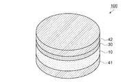
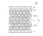
まず、本実施形態の電極複合体が適用された電池として、リチウムイオン電池を例に挙げ、図1及び図2を参照して説明する。図1は第1実施形態のリチウムイオン電池の構成を示す概略斜視図、図2は第1実施形態のリチウムイオン電池の構造を示す概略断面図である。
(First embodiment)
<Battery>
First, as a battery to which the electrode assembly of this embodiment is applied, a lithium ion battery will be described as an example and described with reference to FIGS. 1 and 2. FIG. 1 is a schematic perspective view showing the configuration of the lithium ion battery of the first embodiment, and FIG. 2 is a schematic sectional view showing the structure of the lithium ion battery of the first embodiment.
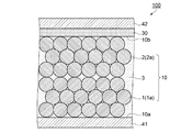
図1に示すように、本実施形態の電池としてのリチウムイオン電池100は、一対の集電体41,42と、一対の集電体41,42の間に設けられた、電極複合体10及び負極30を有している。負極30は例えば金属リチウム層であり、リチウムイオン電池100の充放電におけるリチウムイオン源となっている。リチウムイオン電池100は、例えば、外形がφ3.0mm〜30mm、厚みは例えば100μm〜150μm(マイクロメートル)の円盤状である。このような薄型のリチウムイオン電池100の形状はこれに限定されず、外形は多角形であってもよい。
As shown in FIG. 1, a
集電体41,42は、電池反応により生成された電流を取り出すための電極である。集電体41は、電極複合体10に接するように配置されている。集電体42は、負極30に接するように配置されている。
The
集電体41,42としては、銅(Cu)、マグネシウム(Mg)、チタン(Ti)、鉄(Fe)、コバルト(Co)、ニッケル(Ni)、亜鉛(Zn)、アルミニウム(Al)、ゲルマニウム(Ge)、インジウム(In)、金(Au)、白金(Pt)、銀(Ag)およびパラジウム(Pd)からなる群から選ばれる1種の単体金属、またはこの群から選ばれる2種以上の金属を含む合金やITO、ATO、FTOなど導電性金属酸化物、TiN、ZrN、TaNなどの金属窒化物などを用いて形成される。集電体41,42の形状は、例えば、板状、箔状、または網状である。集電体41,42の表面は、平滑であってもよく、凹凸が形成されていてもよい。
As the
<電極複合体>
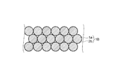
図2に示すように、電極複合体10は、複数の正極活物質粒子1aを焼結して得られた第1焼結体1と、同じく複数の第1固体電解質粒子2aを焼結して得られた第2焼結体2と、第2固体電解質3とを含んで構成されている。第1焼結体1及び第2焼結体2は、それぞれ多孔質であって、第1焼結体1及び第2焼結体2のそれぞれに含まれる空隙や、第1焼結体1と第2焼結体2とが積層された積層体の空隙が、第2固体電解質3によって埋められた状態となっている。なお、図2は、正極活物質粒子1a及び第1固体電解質粒子2aを模式的に示しており、実際の個々の粒子形状は球状とは限らず、大きさは必ずしも同じではない。
<Electrode complex>
As shown in FIG. 2, the
正極活物質粒子1aを構成する正極活物質としては、リチウム(Li)を含む2種以上の金属が含まれるリチウム複合金属化合物が用いられる。リチウム複合金属化合物としては、例えば、LiCoO2、LiNiO2、LiMn2O4、Li2Mn2O3、LiFePO4、Li2FeP2O7、LiMnPO4、LiFeBO3、Li3V2(PO4)3、Li2CuO2、Li2FeSiO4、Li2MnSiO4などのリチウム複合酸化物が挙げられる。また、リチウム複合酸化物以外にも、LiFeF3などのリチウム複合フッ化物を用いてもよい。さらに、これらのリチウム複合金属化合物の一部の原子が他の遷移金属、典型金属、アルカリ金属、アルカリ希土類、ランタノイド、カルコゲナイド、ハロゲンなどで置換されたものも含まれる。また、これらのリチウム複合金属化合物の固溶体を正極活物質として用いてもよい。
As the positive electrode active material constituting the positive electrode
正極活物質を有効に利用する観点から、正極活物質粒子1aの平均粒径(D50)は、0.1μm以上20μm以下であることが好ましく、1.0μm以上10μm以下であることがより好ましい。
From the viewpoint of effectively using the positive electrode active material, the average particle diameter (D50) of the positive electrode
第1固体電解質粒子2aを構成する第1固体電解質としては、リチウム(Li)の例えば、酸化物、硫化物、ハロゲン化物、または窒化物が用いられる。具体的には、SiO2−P2O5−Li2O、SiO2−P2O5−LiCl、Li2O−LiCl−B2O3、Li3.4V0.6Si0.4O4、Li14ZnGe4O16、Li3.6V0.4Ge0.6O4、Li1.3Ti1.7Al0.3(PO4)3、Li2.88PO3.73N0.14、LiNbO3、Li0.35La0.55TiO3、Li7La3Zr2O12、Li6.75La3Zr1.75Nb0.25O12、Li2S−SiS2、Li2S−SiS2−LiI、Li2S−SiS2−P2S5、LiPON、Li3N、LiI、LiI−CaI2、LiI−CaO、LiAlCl4、LiAlF4、LiI−Al2O3、LiFAl2O3、LiBr−Al2O3、Li2O−TiO2、La2O3−Li2O−TiO2、Li3N、Li3NI2、Li3N−LiI−LiOH、Li3N−LiCl、Li6NBr3、LiSO4、Li4SiO4、Li3PO4−Li4SiO4、Li4GeO4−Li3VO4、Li4SiO4−Li3VO4、Li4GeO4−Zn2GeO2、Li4SiO4−LiMoO4、Li3PO4−Li4SiO4、LiSiO4−Li4ZrO4、LiBH4、Li7-xPS6-xClx、Li10GeP2S12のうち少なくとも1つが用いられる。第1固体電解質は、結晶質であっても非晶質(アモルファス)であってもよい。また、これらの組成物の一部原子が他の遷移金属、典型金属、アルカリ金属、アルカリ希土類、ランタノイド、カルコゲナイド、ハロゲンなどで置換された固溶体が、第1固体電解質として用いられてもよい。
As the first solid electrolyte constituting the first
第1固体電解質を有効に利用する観点から、第1固体電解質粒子2aの平均粒径(D50)は、0.1μm以上20μm以下であることが好ましく、1.0μm以上10μm以下であることがより好ましい。
From the viewpoint of effectively using the first solid electrolyte, the average particle diameter (D50) of the first
第2固体電解質3は、リチウムイオンを伝導し、室温で非晶質(ガラス質、アモルファス)である材料が好ましく、且つ、融点が正極活物質や第1固体電解質の融点よりも低い材料が選ばれる。このような第2固体電解質3としては、例えば、Li3BO3、Li3BO3−Li4SiO4、Li3BO3−Li3PO4、Li3BO3−Li2SO4、Li2CO3−Li3BO3などのLi、Bを含むリチウム複合酸化物が挙げられる。
The second
Li3BO3(以降、LBOと称す)のイオン伝導率は、およそ6.0×10⁻¹⁰S/cmであり、融点はおよそ820℃である。Li3BO3−Li4SiO4のイオン伝導率は、およそ4.0×10-6S/cmであり、融点はおよそ720℃である。Li3BO3−Li3PO4のイオン伝導率は、およそ1.0×10-7S/cmであり、融点はおよそ850℃である。Li3BO3−Li2SO4のイオン伝導率は、およそ1.0×10-6S/cmであり、融点はおよそ700℃である。Li2CO3−Li3BO3系であるLi2.2C0.8B0.2O3(以降、簡略化してLCBOと称す)のイオン伝導率は、およそ8.0×10-7S/cmであり、融点は685℃である。 Li 3 BO 3 (hereinafter referred to as LBO) has an ionic conductivity of approximately 6.0 × 10 −10 S / cm and a melting point of approximately 820 ° C. Li 3 BO 3 —Li 4 SiO 4 has an ionic conductivity of approximately 4.0 × 10 −6 S / cm and a melting point of approximately 720 ° C. Li 3 BO 3 —Li 3 PO 4 has an ionic conductivity of approximately 1.0 × 10 −7 S / cm and a melting point of approximately 850 ° C. Li 3 BO 3 —Li 2 SO 4 has an ionic conductivity of approximately 1.0 × 10 −6 S / cm and a melting point of approximately 700 ° C. The ionic conductivity of Li 2.2 C 0.8 B 0.2 O 3 (hereinafter simply referred to as LCBO), which is a Li 2 CO 3 —Li 3 BO 3 system, is approximately 8.0 × 10 −7 S / cm, The melting point is 685 ° C.
リチウムイオン電池100の容量を大きくする観点から、第1固体電解質粒子2aのイオン伝導率は、1.0×10⁻⁵S/cm以上であることが好ましい。電極複合体10が、第2固体電解質3よりもイオン伝導率が高い複数の第1固体電解質粒子2aが焼結された第2焼結体2を含むことによって、第2焼結体2を含まない場合に比べて、より多くの正極活物質粒子1aが電池反応に寄与することになり、リチウムイオン電池100の容量を大きくすることができる。
From the viewpoint of increasing the capacity of the
ここで、固体電解質のイオン伝導率とは、無機電解質自身のイオン伝導率であるバルク伝導率と、無機電解質が結晶質である場合における結晶の粒子間のイオン伝導率である粒界伝導率との総和である総イオン伝導率のことをいう。 Here, the ionic conductivity of the solid electrolyte is the bulk conductivity that is the ionic conductivity of the inorganic electrolyte itself, and the grain boundary conductivity that is the ionic conductivity between the particles of the crystal when the inorganic electrolyte is crystalline. The total ionic conductivity, which is the sum of
固体電解質のイオン伝導率は、例えば、交流インピーダンス法により測定される。測定は、例えば、所定の形状(例えば錠剤型)に成形した固体電解質の両面に電極を形成した試料を用いて行われる。より具体的には、固体電解質粉末を錠剤型にプレス成型する。プレス成形体を大気雰囲気下で焼結する。焼結体に所定の形状(例えば直径0.5cmの円で、厚さ100nm)の電極(例えばAu(金)やPt(プラチナ))をスパッタリング法や真空蒸着法を用いて形成する。測定は、例えば、インピーダンスアナライザー(ソーラトロン社製SI1260)を用いて行われる。 The ionic conductivity of the solid electrolyte is measured by, for example, an AC impedance method. The measurement is performed using, for example, a sample in which electrodes are formed on both surfaces of a solid electrolyte formed into a predetermined shape (for example, a tablet shape). More specifically, the solid electrolyte powder is press-molded into a tablet shape. The press-molded body is sintered in an air atmosphere. An electrode (for example, Au (gold) or Pt (platinum)) having a predetermined shape (for example, a circle having a diameter of 0.5 cm and a thickness of 100 nm) is formed on the sintered body using a sputtering method or a vacuum deposition method. The measurement is performed using, for example, an impedance analyzer (SI1260 manufactured by Solartron).
上述したように、複数の正極活物質粒子1aからなる第1焼結体1及び複数の第1固体電解質粒子2aからなる第2焼結体2は、多孔質であり、内部に複数の空隙(細孔)を有する。これらの空隙は、第1焼結体1及び第2焼結体2のそれぞれの内部で連通している。
As described above, the first
各焼結体の空隙率は、10%以上70%以下であることが好ましく、30%以上70%以下であることがより好ましい。空隙率を制御して第2固体電解質3との接触面積を大きくすることにより、リチウムイオン電池100の容量をより高くすることができる。
The porosity of each sintered body is preferably 10% or more and 70% or less, and more preferably 30% or more and 70% or less. By controlling the porosity and increasing the contact area with the second
空隙率rvは、次式(1)により求めることができる。

リチウムイオン電池100の出力を大きくする観点から、第1焼結体1の抵抗率は、10kΩcm以下であることが好ましい。抵抗率は、例えば、直流分極測定により得られる。直流分極測定においては、例えば、各焼結体の表面に銅箔を貼り付け、この銅箔を電極として用いる。
From the viewpoint of increasing the output of the
第1焼結体1と第2焼結体2との積層体における空隙内には、第2固体電解質3が充填されて正極活物質粒子1aや第1固体電解質粒子2aと接している。各焼結体の空隙に対する、第2固体電解質3の充填率は高い方が好ましいが、例えば60%以上99.9%以下である。
The voids in the laminate of the first
各焼結体において、複数の空隙が内部で網目状に連通している。例えば、正極活物質の一例であるLiCoO2(以降、簡略化してLCOと称する)は、結晶の電子伝導性に異方性があることが知られている。そのため、空隙が特定方向に延びている場合には、空隙が延びている方向と結晶方位との関係によっては、電子伝導し難い状態になってしまうことがある。本実施形態では、第1焼結体1の空隙が網目状に連通しており、正極活物質粒子1aも等方的につながっている。したがって、電気化学的に滑らかな正極活物質粒子1aの連続表面を形成することができ、空隙が異方的に形成されている場合と比較して良好な電子伝導を得ることができる。
In each sintered body, a plurality of voids communicate with each other in a mesh shape. For example, LiCoO 2 (hereinafter simply referred to as LCO), which is an example of a positive electrode active material, is known to have anisotropy in the electronic conductivity of crystals. Therefore, when the gap extends in a specific direction, depending on the relationship between the direction in which the gap extends and the crystal orientation, it may be difficult to conduct electrons. In the present embodiment, the voids of the first
また、各焼結体は内部に多数の空隙を有していることから、表面積が大きくなっている。そのため、各焼結体と第2固体電解質3との接触面積が大きくなり、界面インピーダンスを低減させることができる。なお、リチウムイオン電池100においては、集電体41と第1焼結体1との接触面積よりも、第1焼結体1と第2固体電解質3との接触面積の方が大きい。同様に、集電体42と第2焼結体2との接触面積よりも、第2焼結体2と第2固体電解質3との接触面積のほうが大きい。集電体41と第1焼結体1との界面のほうが、第1焼結体1と第2固体電解質3との界面よりも電荷移動が容易であるため、これらの接触面積が同程度であると、第1焼結体1と第2固体電解質3との界面が電荷移動のボトルネックとなってしまう。本実施形態では、第1焼結体1と第2固体電解質3との接触面積の方が大きいので、このボトルネックを解消し易い。第2焼結体2に対する集電体42や第2固体電解質3との界面についても第1焼結体1の場合と同様である。
Each sintered body has a large surface area because it has a large number of voids inside. Therefore, the contact area between each sintered body and the second
なお、電荷はイオンあるいは電子を指すものであり、正極活物質粒子1aにおける電荷の伝導性を有効に利用する観点から、第1焼結体1の空隙率は、第2焼結体2の空隙率と同じまたは大きいことが好ましい。また、リチウムイオン電池100における電池容量を確保する観点から、第1焼結体1の厚みは、第2焼結体2の厚みと同じまたは厚いことが好ましい。
The charge indicates ions or electrons. From the viewpoint of effectively using the charge conductivity in the positive electrode
<電極複合体の製造方法>
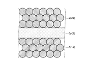
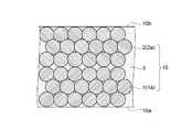
次に、本実施形態の電極複合体10の製造方法について、図3〜図5を参照して説明する。図3は第1実施形態の電極複合体の製造方法を示すフローチャート、図4及び図5は第1実施形態の電極複合体の製造方法を示す概略断面図である。
<Method for producing electrode composite>
Next, the manufacturing method of the
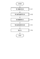
図3に示すように、本実施形態の電極複合体10の製造方法は、第1焼結体形成工程(ステップS1)と、第2焼結体形成工程(ステップS2)と、第2固体電解質充填工程(ステップS3)と、複合化工程(ステップS4)とを備えている。なお、ステップS1が本発明の第1の工程に相当し、ステップS2が本発明の第2の工程に相当し、ステップS3が本発明の第3の工程に相当し、ステップS4が本発明の第4の工程に相当するものである。
As shown in FIG. 3, the manufacturing method of the
ステップS1の第1焼結体形成工程では、まず、正極活物質粒子1aとして、例えば、平均粒径(D50)が1μm〜10μmのLCO粒子を用いた。LCO粒子を例えば150mg秤量して、φ10mmのダイス(成形型)に充填し、50kgNの圧力で1軸プレスを2分間行ってペレット(成形体)を作製した。当該ペレットを基板上に載せ、例えば電気マッフル炉を用いて焼成する。焼成温度は、850℃以上であって、正極活物質粒子1aの融点未満の温度であることが好ましい。この場合、正極活物質粒子1aとしてLCO粒子を用いていることから、焼成温度は、875℃以上1000℃以下であることが好ましい。これにより、正極活物質粒子1a同士を焼結させて、一体化した多孔質体が得られる。焼成温度を850℃以上とすることによって、焼結が十分に進行するとともに、正極活物質粒子1aの結晶内の電子伝導性が確保される。焼成温度を正極活物質粒子1aの融点未満とすることによって、正極活物質粒子1aの結晶内のリチウムイオンが過剰に揮発することを抑え、リチウムイオンの伝導性が維持される。すなわち、電極複合体10の容量を確保することが可能となる。ゆえに、電極複合体10を用いるリチウムイオン電池100において、適切な出力および容量を付与することができる。
In the first sintered body forming step of step S1, first, as the positive electrode
なお、正極活物質粒子1a同士を繋ぎ合わせるバインダー(結着剤)や、第1焼結体1の空隙率を調整するための増孔材などの有機物を含んで上記ペレットを形成してもよいが、焼成後にこれらの有機物が残留すると電荷伝導性に影響を及ぼすので、焼成によって有機物を確実に焼失させることが好ましい。言い換えれば、バインダーや増孔材などの有機物質を含まずにペレットを形成することが望ましい。また、第1焼結体1における空隙率は、正極活物質粒子1aの平均粒径と、ペレットを形成する際の圧力や焼成温度などの焼結条件とを調整することにより制御することができる。
Note that the pellet may be formed by including an organic substance such as a binder (binder) for joining the positive electrode
焼成時間は、例えば5分以上、36時間以下とすることが好ましい。より好ましくは、4時間以上、14時間以下である。以上の処理によって、多孔質の第1焼結体1が得られる。焼成時に用いられる基板の材料は、特に限定されないが、正極活物質粒子1aと反応し難い例えば酸化マグネシウムなどの材料を用いることが好ましい。そして、ステップS2へ進む。
The firing time is preferably, for example, 5 minutes or more and 36 hours or less. More preferably, it is 4 hours or more and 14 hours or less. By the above treatment, the porous first
ステップS2の第2焼結体形成工程では、まず、第1固体電解質粒子2aとして、例えば、Li6.75La3Zr1.75Nb0.25O12(以降、簡略化してLLZrNbOと称す)を用いた。LLZrNbO粒子の平均粒径(D50)は、例えば1.0μm以上20μm以下である。なお、LLZrNbOの融点はおよそ1100℃である。
In the second sintered body forming step of Step S2, first, for example, Li 6.75 La 3 Zr 1.75 Nb 0.25 O 12 (hereinafter simply referred to as LLZrNbO) was used as the first
LLZrNbO粒子を例えば150mg秤量して、φ10mmのダイスに充填し、50kgNの圧力で1軸プレスを2分間行ってペレット(成形体)を作製した。当該ペレットを基板上に載せ、例えば電気マッフル炉を用いて焼成する。焼成温度は、850℃以上であって、第1固体電解質粒子2aの融点未満の温度であることが好ましい。この場合、第1固体電解質粒子2aとしてLLZrNbO粒子を用いていることから、焼成温度は、875℃以上1000℃以下であることが好ましい。これにより、第1固体電解質粒子2a同士を焼結させて、一体化した多孔質体が得られる。焼成温度を850℃以上とすることによって、焼結が十分に進行するとともに、第1固体電解質粒子2aの結晶内のリチウムイオン伝導性が確保される。焼成温度を第1固体電解質粒子2aの融点未満とすることによって、第1固体電解質粒子2aの結晶内のリチウムイオンが過剰に揮発することを抑え、リチウムイオンの伝導性が維持される。すなわち、電極複合体10を用いるリチウムイオン電池100において、適切なイオン伝導性を付与することができる。
For example, 150 mg of LLZrNbO particles were weighed and filled in a φ10 mm die, and uniaxial pressing was performed at a pressure of 50 kgN for 2 minutes to produce pellets (molded bodies). The pellet is placed on a substrate and fired using, for example, an electric muffle furnace. The firing temperature is preferably 850 ° C. or higher and lower than the melting point of the first
なお、ステップS1の第1焼結体形成工程と同様に、バインダーや増孔材などの有機物質を含まずにペレットを形成することが望ましい。また、第1固体電解質粒子2aの平均粒径と、ペレットを形成する際の圧力や焼成温度などの焼結条件とを調整することにより、第2焼結体2における空隙率を制御することができる。
In addition, it is desirable to form a pellet without including organic substances, such as a binder and a pore enlargement material similarly to the 1st sintered compact formation process of step S1. Moreover, the porosity in the 2nd sintered compact 2 can be controlled by adjusting the average particle diameter of the 1st
焼成時間は、例えば5分以上、36時間以下とすることが好ましい。より好ましくは、4時間以上、14時間以下である。以上の処理によって、多孔質の第2焼結体2が得られる。焼成時に用いられる基板の材料は、特に限定されないが、ステップS1と同様に、第1固体電解質と反応し難い例えば酸化マグネシウムなどの材料を用いることが好ましい。そして、ステップS3へ進む。
The firing time is preferably, for example, 5 minutes or more and 36 hours or less. More preferably, it is 4 hours or more and 14 hours or less. By the above treatment, the porous second
ステップS3の第2固体電解質充填工程では、まず、第2固体電解質3のペレット(成形体)を用意する。具体的には、粉体であるLi2CO3及びLi3BO3を質量混合比、4:1で混合し、混合物を例えば150mg秤量して、φ10mmのダイスに充填し、40kgNの圧力で1軸プレスを2分間行って錠剤を得た。この錠剤を例えば電気マッフル炉に入れて、650℃で4時間焼成した。そして、焼成された錠剤を例えばメノウ乳鉢に入れてすり潰して粉砕し、粉砕された粉体を再びφ10mmのダイスに充填し、40kgNの圧力で1軸プレスを2分間行って第2固体電解質3のペレット3p(図4参照)を得た。なお、上記混合物におけるLi2CO3及びLi3BO3の混合比率は、4:1に限定されることはなく、Li2CO3の含有量は、30%以上95%以下が望ましい。
In the second solid electrolyte filling step of step S3, first, pellets (molded bodies) of the second
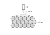
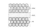
続いて、図4に示すように、第1焼結体1と第2焼結体2との間に、ペレット3pを挟んだ状態で熱処理を施すことにより、第2固体電解質3のペレット3pを溶融させる。ペレット3pは、第1焼結体1と第2焼結体2とに接した状態で溶融するので、ペレット3pの融液は、多孔質である第1焼結体1及び第2焼結体2にむらなく浸み込んでゆく。
Subsequently, as shown in FIG. 4, the
上記熱処理における温度は、第2固体電解質3の融点以上の温度であって、900℃以下の温度であることが好ましい。この場合、第2固体電解質3としてLCBOを用いていることから、熱処理の温度は、LCBOの融点(685℃)よりも高い700℃とした。そして、ステップS4へ進む。
The temperature in the heat treatment is preferably a temperature not lower than the melting point of the second
ステップS4の複合化工程では、第2固体電解質3の融液が浸み込んだ第1焼結体1及び第2焼結体2の積層体を冷却する。これにより、第1焼結体1と第2焼結体2とが積層された積層体に充填された第2固体電解質3の融液が固化し、図5に示すように、第1焼結体1及び第2焼結体2と、第2固体電解質3とが複合化された電極複合体10を得た。
In the composite process of step S4, the laminated body of the first
なお、焼成などの熱処理が施される上記ステップS1,S2,S3のうち少なくともステップS3は、水分が除去された雰囲気(例えば水分量が130ppm以下)下で行うことが好ましい。これによって、リチウム(Li)と水とが反応して水酸化リチウム(LiOH)が副生し、電極複合体10の組成が所望の状態から変化することを防ぐことができる。また、上記ステップS3において、第2固体電解質3としてLCBOを用いる場合には、水分が除去された雰囲気に炭酸ガスを導入することが好ましく、これによって、LCBOから炭素(C)が抜けて組成が変化することを防ぐことができる。
In addition, it is preferable to perform at least step S3 among the above-described steps S1, S2, and S3 subjected to heat treatment such as firing in an atmosphere from which moisture has been removed (for example, the moisture content is 130 ppm or less). Thus, lithium (Li) and water react to generate lithium hydroxide (LiOH) as a by-product, and the composition of the
<リチウムイオン電池の製造方法>
次に、本実施形態のリチウムイオン電池100の製造方法について、図6及び図7を参照して説明する。図6及び図7はリチウムイオン電池の製造方法を示す概略断面図である。
リチウムイオン電池100の製造方法は、上述した製造方法によって得られた電極複合体10に負極30を形成する工程と、集電体41,42を形成する工程とを含むものである。
<Method for producing lithium ion battery>
Next, the manufacturing method of the
The method for manufacturing the
負極30を形成する工程では、図6に示すように、電極複合体10において第2焼結体2が露出する面10bに負極30を形成する。具体的には、金属リチウムを例えばスパッタリング法、真空蒸着法などにより面10bに成膜して負極30とする。負極30の膜厚は例えば50nm〜100μmである。なお、負極30は、リチウムイオン供給源となればよく、金属リチウム以外にも、例えばリチウム複合金属化合物を用いることができる。その場合には、有機金属化合物の加水分解反応などを伴う、所謂ゾル・ゲル法や、有機金属熱分解法などの溶液プロセスの他、適切な金属化合物とガス雰囲気を用いたCVD法、ALD法、金属化合物粒子のスラリーを使用したグリーンシート法やスクリーン印刷法、エアロゾルデポジション法などを用いて負極30を形成してもよい。
In the step of forming the
次に、集電体41,42を形成する工程では、図7に示すように、電極複合体10において第1焼結体1が露出する面10aに集電体41を形成し、負極30に積層して集電体42を形成する。具体的には、電極複合体10の一方の面である面10aに、例えば厚みが1μm〜20μmのアルミニウム箔を貼り付けることにより集電体41とする。また、負極30に例えば厚みが1μm〜20μmの銅箔を貼り付けることにより集電体42とする。なお、集電体41,42の形成方法は、上記したように選定された金属箔を貼り付ける方法に限らず、PVD(Physical Vapor Deposition)法、CVD(Chemical Vapor Deposition)法、PLD(Pulsed Laser Deposition)法、ALD(Atomic Layer Deposition)法およびエアロゾルデポジション法などの気相堆積法、ゾル・ゲル法、有機金属熱分解法、めっきなどの湿式法などを用いて導電膜を形成する方法が挙げられ、集電体形成面との反応性や電気回路に望まれる電気伝導性、電気回路設計に応じて、適当な方法を用いることができる。
Next, in the step of forming the
上記第1実施形態によれば、以下の効果が得られる。
(1)電極複合体10は、正極活物質粒子1aからなる多孔質な第1焼結体1と、第1固体電解質粒子2aからなる多孔質な第2焼結体2と、第1焼結体1と第2焼結体2との積層体に充填された第2固体電解質3とを含んで構成されている。第2固体電解質3は、第1焼結体1及び第2焼結体2の内部の空隙にも充填されている。第1焼結体1において正極活物質粒子1a同士は接触した状態にあり、第2焼結体2においても第1固体電解質粒子2a同士は接触した状態にある。したがって、正極活物質粒子1a間における電子の受け渡しや、第1固体電解質粒子2a間でイオンの受け渡しが容易に行われる。さらに、第1焼結体1と第2焼結体2の積層体における空隙に第2固体電解質3が充填されているので、第1焼結体1と第2焼結体2との間の電荷(電子やイオン)の受け渡しも第2固体電解質3を介して行うことができる。ゆえに、正極活物質粒子1aや第1固体電解質粒子2aを有効に利用して、優れた電荷の伝導性を有する電極複合体10を提供することができる。
According to the first embodiment, the following effects can be obtained.
(1) The
(2)電極複合体10の製造方法によれば、ステップS3では、それぞれ多孔質な第1焼結体1と第2焼結体2との間に、第2固体電解質3のペレット3pを挟んで熱処理を施すことで、ペレット3pを溶融させ、第2固体電解質3の融液を第1焼結体1及び第2焼結体2の空隙に充填する。ステップS4において、冷却を行うことで、第2固体電解質3の融液が固化し、第2固体電解質3は第1焼結体1と第2焼結体2との積層体に充填される。つまり、第1焼結体1と第2焼結体2とが第2固体電解質3によって結合される。したがって、正極活物質粒子1aと第1固体電解質粒子2aとを用いて多孔質な1つの焼結体を形成し、当該焼結体に第2固体電解質3の融液を含浸させる場合に比べて、正極活物質粒子1a同士の接触、及び第1固体電解質粒子2a同士の接触を確実に図ることができる。ゆえに、上記(1)に示すごとく、正極活物質粒子1aや第1固体電解質粒子2aを有効に利用して、優れた電荷伝導性を有する電極複合体10を製造することができる。
(2) According to the method for manufacturing the
(3)電極複合体10を用いることによって、優れた電池特性(充放電特性)を有すると共に、小型で薄型であるにも関わらず大きな電気容量を有するリチウムイオン電池100を提供あるいは製造することができる。
(3) By using the
(第2実施形態)
次に、第2実施形態のリチウムイオン電池とその製造方法について、図8及び図9を参照して説明する。図8は第2実施形態のリチウムイオン電池の構造を示す概略断面図、図9は第2実施形態のリチウムイオン電池の製造方法を示す概略断面図である。第2実施形態のリチウムイオン電池は、上記第1実施形態のリチウムイオン電池100に対して電池の層構成を異ならせたものである。したがって、リチウムイオン電池100と同じ構成には同じ符号を付して詳細な説明は省略する。
(Second Embodiment)
Next, the lithium ion battery of 2nd Embodiment and its manufacturing method are demonstrated with reference to FIG.8 and FIG.9. FIG. 8 is a schematic cross-sectional view showing the structure of the lithium ion battery of the second embodiment, and FIG. 9 is a schematic cross-sectional view showing a method for manufacturing the lithium ion battery of the second embodiment. The lithium ion battery according to the second embodiment is different from the
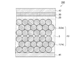
図8に示すように、本実施形態のリチウムイオン電池200は、一対の集電体41,42と、一対の集電体41,42の間に設けられた、電極複合体10、耐リチウム還元層20、負極30を有している。リチウムイオン電池200は、上記第1実施形態のリチウムイオン電池100に対して、電極複合体10と負極30との間に耐リチウム還元層20を設けたものである。
As shown in FIG. 8, the
耐リチウム還元層20は、電極複合体10における第2固体電解質3に用いられる上述した材料を用いることができる。つまり、リチウムイオンを伝導し、室温で非晶質(ガラス質、アモルファス)である材料が好ましく、例えば、Li3BO3、Li3BO3−Li4SiO4、Li3BO3−Li3PO4、Li3BO3−Li2SO4、Li2CO3−Li3BO3などのLi、Bを含むリチウム複合酸化物が挙げられる。さらには、耐リチウム還元層20と第2固体電解質3とは同じ材料を用いることが好ましい。耐リチウム還元層20の厚みは、およそ0.1μmから10μm程度が好ましいが、材料特性やリチウムイオン電池200の設計により所望の値とすることができる。
The lithium-
このようなリチウムイオン電池200の製造方法は、図9に示すように、上記第1実施形態の電極複合体10の製造方法を用いて形成された電極複合体10の他方の面としての第2焼結体2側の面10bに、耐リチウム還元層20を積層して形成する工程を含んでいる。耐リチウム還元層20の形成方法としては、例えば、有機金属化合物の加水分解反応などを伴う、所謂ゾル・ゲル法や、有機金属熱分解法などの溶液プロセスの他、適切な金属化合物とガス雰囲気を用いたCVD法、ALD法、固体電解質粒子のスラリーを使用したグリーンシート法やスクリーン印刷法、エアロゾルデポジション法、適切なターゲットとガス雰囲気を用いたスパッタリング法、PLD法、融液や溶液を用いたフラックス法など、を用いることができる。
As shown in FIG. 9, the manufacturing method of such a
また、形成された耐リチウム還元層20の負極30側の面に、必要に応じて各種成形法、加工法を組み合わせて、トレンチ、グレーチング、ピラーなどの凹凸構造を設けることもできる。さらに、耐リチウム還元層20は、1層だけではなく、例えば結晶質で形成された層の表面に、非晶質であるガラス電解質層を形成するなど、多層化された構造としてもよい。
In addition, the surface of the formed lithium-
上記第2実施形態によれば、上記第1実施形態の(1)〜(3)の効果に加えて、以下の効果が得られる。
(4)電極複合体10と負極30との間に耐リチウム還元層20が形成されているため、それぞれが結晶性の粒子からなる第1焼結体1及び第2焼結体2を介して、集電体41(正極)と負極30とが電気的に短絡することを防ぐことができる。さらに、リチウムイオン電池200において充放電が繰り返されることで、負極30のリチウムイオン収納性が低下してリチウム金属が析出したとしても、負極30側から析出して電極複合体10側に発達した樹枝状リチウム金属による正・負極間短絡(デンドライトショート)を効果的に防止することができる。すなわち、高い信頼性品質を有するリチウムイオン電池200を提供あるいは製造することができる。
According to the second embodiment, in addition to the effects (1) to (3) of the first embodiment, the following effects can be obtained.
(4) Since the lithium-
(第3実施形態)
<他のリチウムイオン電池>
次に、第3実施形態のリチウムイオン電池について、図10を参照して説明する。図10は第3実施形態のリチウムイオン電池の構造を示す概略断面図である。第3実施形態のリチウムイオン電池は、上記第2実施形態のリチウムイオン電池200に対して電極複合体10の構成(構造)を異ならせたものである。したがって、リチウムイオン電池200と同じ構成には同じ符号を付して詳細な説明は省略する。
(Third embodiment)
<Other lithium ion batteries>
Next, the lithium ion battery of 3rd Embodiment is demonstrated with reference to FIG. FIG. 10 is a schematic cross-sectional view showing the structure of the lithium ion battery of the third embodiment. The lithium ion battery according to the third embodiment is different from the
図10に示すように、本実施形態のリチウムイオン電池300は、一対の集電体41,42と、一対の集電体41,42の間に設けられた、電極複合体10B、耐リチウム還元層20、負極30を有している。以降、本実施形態の特徴部分である電極複合体10Bについて説明する。
As shown in FIG. 10, the
電極複合体10Bは、複数の正極活物質粒子1aが焼結されてなる多孔質な第1焼結体1Bと、複数の第1固体電解質粒子2aが焼結されてなる同じく多孔質な第2焼結体2と、第2固体電解質3とが複合化されたものである。
The
第1焼結体1Bにおいて、正極活物質粒子1aの表面には、第1固体電解質2bが形成されている。第1固体電解質2bは、第1固体電解質粒子2aを構成する材料と同じ材料を用いて形成されている。図10においては、正極活物質粒子1aの表面のすべてを覆うように第1固体電解質2bを表記したが、実際には、正極活物質粒子1aの表面のすべてを覆ってはいない。第1固体電解質2bは、焼結された複数の正極活物質粒子1aの表面のうち、正極活物質粒子1aが互いに接触している部分を除いた表面の少なくとも一部に形成されている。このような構成とすることで、第2固体電解質3よりもイオン伝導性が優れている第1固体電解質2bと正極活物質粒子1aが接する面積を電極複合体10に比べて実質的に増やすようにしている。これによって、第1焼結体1Bと第2固体電解質3との界面においてリチウムイオンの伝導性を向上させたものである。
In the first
<他の電極複合体の製造方法>
次に、電極複合体10Bの製造方法について、図11〜図15を参照して説明する。図11は第3実施形態の電極複合体の製造方法を示すフローチャート、図12〜図15は第3実施形態の電極複合体の製造方法を示す概略断面図である。
<Manufacturing method of other electrode composite>
Next, a method for manufacturing the
図11に示すように、本実施形態の電極複合体10Bの製造方法は、第1焼結体形成工程(ステップS11)と、第1固体電解質形成工程(ステップS12)と、第2焼結体形成工程(ステップS13)と、第2固体電解質充填工程(ステップS14)と、複合化工程(ステップS15)と、を備えている。なお、上記第1実施形態の電極複合体10の製造方法に対して、ステップS1と本実施形態のステップS11は基本的に同じである。また、ステップS2と本実施形態のステップS13、及びステップS3と本実施形態のステップS14、並びにステップS4と本実施形態のステップS15は、いずれも基本的に同じである。なお、ステップS12が本発明の第5の工程及び第6の工程を含むものである。
As shown in FIG. 11, the manufacturing method of the
ステップS11の第1焼結体形成工程では、上記第1実施形態のステップS1と同様にして、複数の正極活物質粒子1aを焼結してなる多孔質な第1焼結体1を形成する。そして、ステップS12へ進む。
In the first sintered body forming step of step S11, a porous first
ステップS12の第1固体電解質形成工程では、まず、第1固体電解質2bの前駆体溶液2p(図12参照)を用意する。第1固体電解質2bの前駆体溶液2pは、少なくとも第1固体電解質2bの前駆体と溶媒とを含むものである。前駆体溶液2pとしては、以下の(A)〜(C)の例が挙げられる。
In the first solid electrolyte formation step of step S12, first, a
(A)金属原子を第1固体電解質2bの組成に従った割合で含み、酸化により第1固体電解質2bとなる塩を有する組成物。
(B)金属原子を第1固体電解質2bの組成に従った割合で含む金属アルコキシドを有する組成物。
(C)第1固体電解質2bの微粒子、または金属原子を第1固体電解質2bの組成に従った割合で含む微粒子ゾルを溶媒、または(A)もしくは(B)に分散させた分散液。
なお、(A)に含まれる塩には、金属錯体が含まれる。また、(B)は、いわゆるゾル・ゲル法を用いて第1固体電解質2bを形成する場合に用いられるものである。
(A) A composition comprising a metal atom in a proportion according to the composition of the first
(B) The composition which has a metal alkoxide which contains a metal atom in the ratio according to the composition of the 1st
(C) A dispersion in which fine particles of the first
In addition, the metal complex is contained in the salt contained in (A). (B) is used when the first
前駆体溶液2pに含まれる溶媒は、上記(A)〜(C)に含まれる前駆体によって、水または水系溶媒、あるいは非水系である有機溶媒の中から適宜選ばれる。
The solvent contained in the
本実施形態では、第2固体電解質3よりも高いイオン伝導度を示す第1固体電解質2bとしてLLZrNbOを用いた。LLZrNbOの結晶粒子を溶媒中に分散させて前駆体溶液2pとして用いる。ここで用いられるLLZrNbOの平均粒径(D50)は、例えば30nm〜10μmである。
In the present embodiment, LLZrNbO is used as the first
次に、図12に示すように、ステップS11で得られた第1焼結体1に、用意した前駆体溶液2pを塗布する。前駆体溶液2pの塗布は、第1焼結体1の嵩密度を考慮して決められる塗布量を無駄なく塗布できるように、定量吐出器50を用いて塗布することが好ましい。塗布された前駆体溶液2pは多孔質な第1焼結体1に浸み込んでゆく。そして、熱処理を施すことによって、第1焼結体1に浸み込ませた前駆体溶液2pから溶媒成分を除去する。さらに、焼成を行うことにより、図13に示すように、正極活物質粒子1aの表面の一部に第1固体電解質2bを析出させて形成する。
Next, as shown in FIG. 12, the
溶媒の除去は、加熱、減圧、送風など通常知られた方法を少なくとも1つ用いて行う。この場合の焼成は、大気雰囲気下、第1焼結体1を形成する際の焼成温度よりも低い温度で行う。この場合の焼成温度は、例えば500℃以上900℃以下の温度範囲である。焼成温度が高すぎると、正極活物質粒子1aと第1固体電解質2bとの界面における固相反応により、電気化学的に不活性な副生物が生成されてしまう場合がある。このような副生物はリチウムイオン電池300の特性に悪影響を与える。また、焼成温度が低すぎると、第1固体電解質2bの結晶性が悪く、十分なイオン伝導性が得られない場合がある。そして、ステップS13へ進む。
The removal of the solvent is performed by using at least one generally known method such as heating, decompression, and air blowing. The firing in this case is performed in an air atmosphere at a temperature lower than the firing temperature when forming the first
ステップS13の第2焼結体形成工程では、上記第1実施形態のステップS2と同様にして、複数の第1固体電解質粒子2aを焼結してなる多孔質な第2焼結体2を形成する。そして、ステップS14へ進む。
In the second sintered body forming step of step S13, a porous second
ステップS14の第2固体電解質充填工程では、上記第1実施形態のステップS3と同様に、まず、第2固体電解質3のペレット3p(図14参照)を用意する。続いて、図14に示すように、第1焼結体1Bと第2焼結体2との間に、ペレット3pを挟んだ状態で熱処理を施すことにより、第2固体電解質3のペレット3pを溶融させる。ペレット3pの融液は、多孔質である第1焼結体1B及び第2焼結体2に浸み込んでゆく。
In the second solid electrolyte filling step of step S14, as in step S3 of the first embodiment, first,
上記熱処理における温度は、上記第1実施形態のステップS3と同様に、第2固体電解質3の融点以上の温度であって、900℃以下の温度であることが好ましい。この場合も、第2固体電解質3としてLCBOを用いていることから、熱処理の温度は、LCBOの融点(685℃)よりも高い700℃とした。そして、ステップS15へ進む。
The temperature in the heat treatment is preferably a temperature equal to or higher than the melting point of the second
ステップS15の複合化工程では、第2固体電解質3の融液が浸み込んだ第1焼結体1B及び第2焼結体2の積層体を冷却する。これにより、第1焼結体1Bと第2焼結体2とが積層された積層体に充填された第2固体電解質3の融液が固化し、図15に示すように、第1焼結体1B及び第2焼結体2と、第2固体電解質3とが複合化された電極複合体10Bを得た。
In the composite process of step S15, the laminated body of the first
上記第3実施形態によれば、第1焼結体1Bは、焼結された複数の正極活物質粒子1aの表面の一部に形成され、第2固体電解質3よりも優れたイオン伝導性を有する第1固体電解質2bを含んでいることから、負極30側から離れた位置にある正極活物質粒子1aも電池反応に寄与することになる。したがって、電極複合体10Bを用いることにより、より優れた電池特性(充放電特性)を有するリチウムイオン電池300を提供あるいは製造することができる。
According to the third embodiment, the first
本発明は、上記した実施形態に限られるものではなく、請求の範囲および明細書全体から読み取れる発明の要旨あるいは思想に反しない範囲で適宜変更可能であり、そのような変更を伴う電極複合体および該電極複合体の製造方法ならびに該電極複合体を適用する電池もまた本発明の技術的範囲に含まれるものである。上記実施形態以外にも様々な変形例が考えられる。以下、変形例を挙げて説明する。 The present invention is not limited to the above-described embodiment, and can be appropriately changed without departing from the gist or concept of the invention that can be read from the claims and the entire specification. The method for producing the electrode composite and the battery to which the electrode composite is applied are also included in the technical scope of the present invention. Various modifications other than the above embodiment are conceivable. Hereinafter, a modification will be described.
(変形例1)上記第1実施形態のリチウムイオン電池100において、電極複合体10の代わりに、上記第3実施形態に示した電極複合体10Bを用いてもよい。
(Modification 1) In the
(変形例2)上記実施形態のリチウムイオン電池100,200,300において、一対の集電体41,42は必須ではなく、一対の集電体41,42のうちの一方が形成された状態であってもよい。例えば、集電体41をAu(金)で構成し、リチウムイオン電池をスタックして用いるのであれば、集電体42を不要とすることもできる。
(Modification 2) In the
(変形例3)上記第1実施形態の電極複合体10の製造方法において、第2焼結体2の形成工程(ステップS2)は、第1焼結体1の形成工程(ステップS1)の後に実施されることに限定されない。ステップS1とステップS2とを並行して実施してもよい。なお、上記第3実施形態の電極複合体10Bの製造方法においても同様である。
(Modification 3) In the method for manufacturing the
1,1B…第1焼結体、1a…活物質としての正極活物質粒子、2…第2焼結体、2a…第1固体電解質としての第1固体電解質粒子、3…第2固体電解質、10,10B…電極複合体、20…耐リチウム還元層、30…負極、41,42…集電体、100,200,300…電池としてのリチウムイオン電池。
DESCRIPTION OF
Claims (18)
第1固体電解質を含む多孔質な第2焼結体と、
前記第1焼結体と前記第2焼結体との積層体に充填された第2固体電解質とを含むことを特徴とする電極複合体。 A porous first sintered body containing an active material;
A porous second sintered body containing a first solid electrolyte;
An electrode composite comprising a second solid electrolyte filled in a laminate of the first sintered body and the second sintered body.
前記第1固体電解質は、Li、La、Zrを含む酸化物であり、
前記第2固体電解質は、Li、Bを含む酸化物であることを特徴とする請求項5に記載の電極複合体。 The active material is an oxide containing Li and Co,
The first solid electrolyte is an oxide containing Li, La, Zr,
The electrode composite according to claim 5, wherein the second solid electrolyte is an oxide containing Li and B.
第1固体電解質の粒子を用いて多孔質な第2焼結体を形成する第2の工程と、
前記第1焼結体と前記第2焼結体との積層体に第2固体電解質の融液を含浸させる第3の工程と、
前記第2固体電解質の融液が含浸した前記積層体を冷却する第4の工程と、を備えたことを特徴とする電極複合体の製造方法。 A first step of forming a porous first sintered body using particles of an active material;
A second step of forming a porous second sintered body using the particles of the first solid electrolyte;
A third step of impregnating a laminate of the first sintered body and the second sintered body with a melt of the second solid electrolyte;
And a fourth step of cooling the laminate impregnated with the melt of the second solid electrolyte.
前記第1固体電解質は、Li、La、Zrを含む酸化物であり、
前記第2固体電解質は、Li、Bを含む酸化物であって、
前記第3の工程では、700℃以上900℃未満の温度で前記第2固体電解質を溶融させることを特徴とする請求項11に記載の電極複合体の製造方法。 The active material is an oxide containing Li and Co,
The first solid electrolyte is an oxide containing Li, La, Zr,
The second solid electrolyte is an oxide containing Li and B,
The method for producing an electrode assembly according to claim 11, wherein, in the third step, the second solid electrolyte is melted at a temperature of 700 ° C or higher and lower than 900 ° C.
前記溶液が含浸した前記第1焼結体を加熱して前記溶媒を除去する第6の工程と、を含むことを特徴とする請求項8乃至12のいずれか一項に記載の電極複合体の製造方法。 The first step includes a fifth step of impregnating the first sintered body with a solution containing the first solid electrolyte and a solvent;
A sixth step of heating the first sintered body impregnated with the solution to remove the solvent, The electrode assembly according to any one of claims 8 to 12, Production method.
前記第3の工程における雰囲気は、炭酸ガスを含むことを特徴とする請求項14に記載の電極複合体の製造方法。 The second solid electrolyte is an oxide containing Li, C, and B,
The method for producing an electrode assembly according to claim 14, wherein the atmosphere in the third step contains carbon dioxide gas.
前記電極複合体の他方の面に負極を形成する工程を備えたことを特徴とする請求項16に記載の電池の製造方法。 The active material is a positive electrode active material made of a lithium composite metal compound,
The battery manufacturing method according to claim 16, further comprising a step of forming a negative electrode on the other surface of the electrode composite.
Priority Applications (1)
| Application Number | Priority Date | Filing Date | Title |
|---|---|---|---|
| JP2016052047A JP2017168282A (en) | 2016-03-16 | 2016-03-16 | Electrode composite, battery, method for manufacturing electrode composite, and method for manufacturing battery |
Applications Claiming Priority (1)
| Application Number | Priority Date | Filing Date | Title |
|---|---|---|---|
| JP2016052047A JP2017168282A (en) | 2016-03-16 | 2016-03-16 | Electrode composite, battery, method for manufacturing electrode composite, and method for manufacturing battery |
Publications (2)
| Publication Number | Publication Date |
|---|---|
| JP2017168282A true JP2017168282A (en) | 2017-09-21 |
| JP2017168282A5 JP2017168282A5 (en) | 2019-04-11 |
Family
ID=59913639
Family Applications (1)
| Application Number | Title | Priority Date | Filing Date |
|---|---|---|---|
| JP2016052047A Withdrawn JP2017168282A (en) | 2016-03-16 | 2016-03-16 | Electrode composite, battery, method for manufacturing electrode composite, and method for manufacturing battery |
Country Status (1)
| Country | Link |
|---|---|
| JP (1) | JP2017168282A (en) |
Cited By (4)
| Publication number | Priority date | Publication date | Assignee | Title |
|---|---|---|---|---|
| JP2019061867A (en) * | 2017-09-27 | 2019-04-18 | セイコーエプソン株式会社 | Lithium battery, method of manufacturing lithium battery, and electronic apparatus |
| CN110137564A (en) * | 2019-04-09 | 2019-08-16 | 中国科学院合肥物质科学研究院 | A kind of porous type solid electrolyte preparation method for lithium ion battery |
| WO2022202901A1 (en) * | 2021-03-26 | 2022-09-29 | 富士フイルム株式会社 | Solid electrolyte layered sheet, all solid secondary battery, and method for producing all solid secondary battery |
| EP3961753A4 (en) * | 2019-04-26 | 2023-09-20 | NGK Insulators, Ltd. | Lithium secondary battery |
Citations (5)
| Publication number | Priority date | Publication date | Assignee | Title |
|---|---|---|---|---|
| JP2010080426A (en) * | 2008-04-10 | 2010-04-08 | Sumitomo Electric Ind Ltd | Method of manufacturing cathode body and cathode body |
| JP2011165410A (en) * | 2010-02-05 | 2011-08-25 | Ohara Inc | All solid lithium ion secondary battery and method for manufacturing the same |
| JP2012209256A (en) * | 2011-03-15 | 2012-10-25 | Ohara Inc | All-solid secondary battery |
| JP2016001597A (en) * | 2014-05-19 | 2016-01-07 | Tdk株式会社 | Lithium ion secondary battery |
| JP2016025020A (en) * | 2014-07-23 | 2016-02-08 | セイコーエプソン株式会社 | Electrode complex, lithium battery, and electrode complex manufacturing method |
-
2016
- 2016-03-16 JP JP2016052047A patent/JP2017168282A/en not_active Withdrawn
Patent Citations (5)
| Publication number | Priority date | Publication date | Assignee | Title |
|---|---|---|---|---|
| JP2010080426A (en) * | 2008-04-10 | 2010-04-08 | Sumitomo Electric Ind Ltd | Method of manufacturing cathode body and cathode body |
| JP2011165410A (en) * | 2010-02-05 | 2011-08-25 | Ohara Inc | All solid lithium ion secondary battery and method for manufacturing the same |
| JP2012209256A (en) * | 2011-03-15 | 2012-10-25 | Ohara Inc | All-solid secondary battery |
| JP2016001597A (en) * | 2014-05-19 | 2016-01-07 | Tdk株式会社 | Lithium ion secondary battery |
| JP2016025020A (en) * | 2014-07-23 | 2016-02-08 | セイコーエプソン株式会社 | Electrode complex, lithium battery, and electrode complex manufacturing method |
Cited By (4)
| Publication number | Priority date | Publication date | Assignee | Title |
|---|---|---|---|---|
| JP2019061867A (en) * | 2017-09-27 | 2019-04-18 | セイコーエプソン株式会社 | Lithium battery, method of manufacturing lithium battery, and electronic apparatus |
| CN110137564A (en) * | 2019-04-09 | 2019-08-16 | 中国科学院合肥物质科学研究院 | A kind of porous type solid electrolyte preparation method for lithium ion battery |
| EP3961753A4 (en) * | 2019-04-26 | 2023-09-20 | NGK Insulators, Ltd. | Lithium secondary battery |
| WO2022202901A1 (en) * | 2021-03-26 | 2022-09-29 | 富士フイルム株式会社 | Solid electrolyte layered sheet, all solid secondary battery, and method for producing all solid secondary battery |
Similar Documents
| Publication | Publication Date | Title |
|---|---|---|
| CN106159312B (en) | Solid electrolyte battery, method for producing same, electrode assembly, and composite solid electrolyte | |
| JP6201327B2 (en) | Method for producing electrode composite for lithium battery, electrode composite for lithium battery, and lithium battery | |
| CN106252590B (en) | Electrode composite, method for producing electrode composite, and lithium battery | |
| JP6464556B2 (en) | Electrode composite manufacturing method, electrode composite, and battery | |
| US20160028103A1 (en) | Electrode assembly, lithium battery, and method for producing electrode assembly | |
| JP5987103B2 (en) | All solid ion secondary battery | |
| JP2017004672A (en) | Electrode composite, method for manufacturing electrode composite, and lithium battery | |
| JP2014154236A (en) | Method for manufacturing electrode composite body | |
| US20140216632A1 (en) | Method for producing active material molded body, active material molded body, method for producing lithium battery, and lithium battery | |
| WO2017130818A1 (en) | Method for producing electrode composite body and method for manufacturing lithium ion battery | |
| JP2017004705A (en) | Electrode composite body and cell | |
| WO2014020654A1 (en) | All-solid ion secondary cell | |
| CN111048825B (en) | Solid state electrode with non-carbon electron conductive additive | |
| JP6966502B2 (en) | A solid electrolyte sheet, a negative electrode sheet for an all-solid-state secondary battery, an all-solid-state secondary battery, and a method for manufacturing these. | |
| JP2013105646A (en) | Composition for forming solid electrolyte layer, method for forming solid electrolyte layer, solid electrolyte layer, and lithium ion secondary battery | |
| JP2017084515A (en) | Negative electrode layer, and all-solid-state lithium ion secondary battery | |
| JP2017004783A (en) | Method for manufacturing electrode complex, electrode complex and lithium battery | |
| JP2016143477A (en) | Electrode complex, manufacturing method of electrode complex and battery | |
| JP2017033689A (en) | Electrode assembly, all-solid secondary battery, and method for manufacturing electrode assembly | |
| JP2017168282A (en) | Electrode composite, battery, method for manufacturing electrode composite, and method for manufacturing battery | |
| JP6907805B2 (en) | Complexes, lithium batteries, composite manufacturing methods, lithium battery manufacturing methods, electronic devices | |
| JP6163774B2 (en) | Method for producing composite and method for producing lithium battery | |
| JP6578743B2 (en) | Electrode manufacturing method | |
| JP2017139142A (en) | Solid electrolyte, method for producing the same, and battery | |
| JP6624892B2 (en) | Method for producing electrode composite, electrode composite and battery |
Legal Events
| Date | Code | Title | Description |
|---|---|---|---|
| RD03 | Notification of appointment of power of attorney |
Free format text: JAPANESE INTERMEDIATE CODE: A7423 Effective date: 20181119 |
|
| A521 | Request for written amendment filed |
Free format text: JAPANESE INTERMEDIATE CODE: A523 Effective date: 20190227 |
|
| A621 | Written request for application examination |
Free format text: JAPANESE INTERMEDIATE CODE: A621 Effective date: 20190227 |
|
| RD05 | Notification of revocation of power of attorney |
Free format text: JAPANESE INTERMEDIATE CODE: A7425 Effective date: 20190322 |
|
| A977 | Report on retrieval |
Free format text: JAPANESE INTERMEDIATE CODE: A971007 Effective date: 20191127 |
|
| A131 | Notification of reasons for refusal |
Free format text: JAPANESE INTERMEDIATE CODE: A131 Effective date: 20200107 |
|
| A761 | Written withdrawal of application |
Free format text: JAPANESE INTERMEDIATE CODE: A761 Effective date: 20200309 |