JP2017167146A - Method for monitoring transport of liquid containers in automatic analyzer - Google Patents
Method for monitoring transport of liquid containers in automatic analyzer Download PDFInfo
- Publication number
- JP2017167146A JP2017167146A JP2017050695A JP2017050695A JP2017167146A JP 2017167146 A JP2017167146 A JP 2017167146A JP 2017050695 A JP2017050695 A JP 2017050695A JP 2017050695 A JP2017050695 A JP 2017050695A JP 2017167146 A JP2017167146 A JP 2017167146A
- Authority
- JP
- Japan
- Prior art keywords
- clamp
- clamp gripper
- liquid container
- gripper
- distance
- Prior art date
- Legal status (The legal status is an assumption and is not a legal conclusion. Google has not performed a legal analysis and makes no representation as to the accuracy of the status listed.)
- Granted
Links
- 239000007788 liquid Substances 0.000 title claims abstract description 120
- 238000000034 method Methods 0.000 title claims abstract description 49
- 238000012544 monitoring process Methods 0.000 title claims abstract description 8
- 238000012546 transfer Methods 0.000 claims abstract description 56
- 230000008859 change Effects 0.000 claims description 30
- 238000006243 chemical reaction Methods 0.000 claims description 14
- 230000008878 coupling Effects 0.000 claims description 10
- 238000010168 coupling process Methods 0.000 claims description 10
- 238000005859 coupling reaction Methods 0.000 claims description 10
- 238000004458 analytical method Methods 0.000 claims description 6
- 230000032258 transport Effects 0.000 description 27
- 239000003153 chemical reaction reagent Substances 0.000 description 17
- 230000008569 process Effects 0.000 description 14
- 239000000523 sample Substances 0.000 description 13
- 238000005259 measurement Methods 0.000 description 9
- 230000009471 action Effects 0.000 description 3
- 238000001514 detection method Methods 0.000 description 3
- 238000010586 diagram Methods 0.000 description 3
- 238000011534 incubation Methods 0.000 description 3
- 238000012360 testing method Methods 0.000 description 3
- 239000012491 analyte Substances 0.000 description 2
- 239000008280 blood Substances 0.000 description 2
- 210000004369 blood Anatomy 0.000 description 2
- 210000001124 body fluid Anatomy 0.000 description 2
- 238000011109 contamination Methods 0.000 description 2
- 230000000694 effects Effects 0.000 description 2
- 230000006870 function Effects 0.000 description 2
- 230000003287 optical effect Effects 0.000 description 2
- 238000005375 photometry Methods 0.000 description 2
- 230000004044 response Effects 0.000 description 2
- 238000003756 stirring Methods 0.000 description 2
- 229910000639 Spring steel Inorganic materials 0.000 description 1
- 238000013019 agitation Methods 0.000 description 1
- 238000005842 biochemical reaction Methods 0.000 description 1
- 230000008033 biological extinction Effects 0.000 description 1
- 239000010839 body fluid Substances 0.000 description 1
- 230000015556 catabolic process Effects 0.000 description 1
- 238000003759 clinical diagnosis Methods 0.000 description 1
- 238000006731 degradation reaction Methods 0.000 description 1
- 230000006866 deterioration Effects 0.000 description 1
- 239000006260 foam Substances 0.000 description 1
- 238000004020 luminiscence type Methods 0.000 description 1
- 238000012423 maintenance Methods 0.000 description 1
- 239000013307 optical fiber Substances 0.000 description 1
- 239000013610 patient sample Substances 0.000 description 1
- 230000008439 repair process Effects 0.000 description 1
- 238000000926 separation method Methods 0.000 description 1
- 239000000126 substance Substances 0.000 description 1
- 239000000725 suspension Substances 0.000 description 1
- 238000004879 turbidimetry Methods 0.000 description 1
- 230000000007 visual effect Effects 0.000 description 1
Images


Classifications
-
- G—PHYSICS
- G01—MEASURING; TESTING
- G01N—INVESTIGATING OR ANALYSING MATERIALS BY DETERMINING THEIR CHEMICAL OR PHYSICAL PROPERTIES
- G01N35/00—Automatic analysis not limited to methods or materials provided for in any single one of groups G01N1/00 - G01N33/00; Handling materials therefor
- G01N35/0099—Automatic analysis not limited to methods or materials provided for in any single one of groups G01N1/00 - G01N33/00; Handling materials therefor comprising robots or similar manipulators
-
- B—PERFORMING OPERATIONS; TRANSPORTING
- B01—PHYSICAL OR CHEMICAL PROCESSES OR APPARATUS IN GENERAL
- B01L—CHEMICAL OR PHYSICAL LABORATORY APPARATUS FOR GENERAL USE
- B01L9/00—Supporting devices; Holding devices
- B01L9/06—Test-tube stands; Test-tube holders
-
- B—PERFORMING OPERATIONS; TRANSPORTING
- B25—HAND TOOLS; PORTABLE POWER-DRIVEN TOOLS; MANIPULATORS
- B25J—MANIPULATORS; CHAMBERS PROVIDED WITH MANIPULATION DEVICES
- B25J13/00—Controls for manipulators
- B25J13/08—Controls for manipulators by means of sensing devices, e.g. viewing or touching devices
- B25J13/086—Proximity sensors
-
- B—PERFORMING OPERATIONS; TRANSPORTING
- B25—HAND TOOLS; PORTABLE POWER-DRIVEN TOOLS; MANIPULATORS
- B25J—MANIPULATORS; CHAMBERS PROVIDED WITH MANIPULATION DEVICES
- B25J17/00—Joints
- B25J17/02—Wrist joints
- B25J17/0208—Compliance devices
-
- B—PERFORMING OPERATIONS; TRANSPORTING
- B01—PHYSICAL OR CHEMICAL PROCESSES OR APPARATUS IN GENERAL
- B01L—CHEMICAL OR PHYSICAL LABORATORY APPARATUS FOR GENERAL USE
- B01L2200/00—Solutions for specific problems relating to chemical or physical laboratory apparatus
- B01L2200/02—Adapting objects or devices to another
- B01L2200/023—Adapting objects or devices to another adapted for different sizes of tubes, tips or container
-
- B—PERFORMING OPERATIONS; TRANSPORTING
- B01—PHYSICAL OR CHEMICAL PROCESSES OR APPARATUS IN GENERAL
- B01L—CHEMICAL OR PHYSICAL LABORATORY APPARATUS FOR GENERAL USE
- B01L2200/00—Solutions for specific problems relating to chemical or physical laboratory apparatus
- B01L2200/14—Process control and prevention of errors
-
- B—PERFORMING OPERATIONS; TRANSPORTING
- B01—PHYSICAL OR CHEMICAL PROCESSES OR APPARATUS IN GENERAL
- B01L—CHEMICAL OR PHYSICAL LABORATORY APPARATUS FOR GENERAL USE
- B01L2200/00—Solutions for specific problems relating to chemical or physical laboratory apparatus
- B01L2200/18—Transport of container or devices
-
- B—PERFORMING OPERATIONS; TRANSPORTING
- B01—PHYSICAL OR CHEMICAL PROCESSES OR APPARATUS IN GENERAL
- B01L—CHEMICAL OR PHYSICAL LABORATORY APPARATUS FOR GENERAL USE
- B01L2300/00—Additional constructional details
- B01L2300/12—Specific details about materials
- B01L2300/123—Flexible; Elastomeric
-
- G—PHYSICS
- G01—MEASURING; TESTING
- G01N—INVESTIGATING OR ANALYSING MATERIALS BY DETERMINING THEIR CHEMICAL OR PHYSICAL PROPERTIES
- G01N35/00—Automatic analysis not limited to methods or materials provided for in any single one of groups G01N1/00 - G01N33/00; Handling materials therefor
- G01N35/00584—Control arrangements for automatic analysers
- G01N35/00594—Quality control, including calibration or testing of components of the analyser
- G01N35/00613—Quality control
- G01N35/00623—Quality control of instruments
- G01N2035/00643—Quality control of instruments detecting malfunctions in conveying systems
Landscapes
- Engineering & Computer Science (AREA)
- Robotics (AREA)
- Chemical & Material Sciences (AREA)
- Mechanical Engineering (AREA)
- Health & Medical Sciences (AREA)
- Physics & Mathematics (AREA)
- Clinical Laboratory Science (AREA)
- Chemical Kinetics & Catalysis (AREA)
- Human Computer Interaction (AREA)
- Life Sciences & Earth Sciences (AREA)
- Analytical Chemistry (AREA)
- Biochemistry (AREA)
- General Health & Medical Sciences (AREA)
- General Physics & Mathematics (AREA)
- Immunology (AREA)
- Pathology (AREA)
- Automatic Analysis And Handling Materials Therefor (AREA)
Abstract
Description
本発明は、自動分析装置の分野のものであり、液体容器の自動輸送を監視する方法、および液体容器を輸送するデバイスの適切な働きを確認する方法に関する。 The present invention is in the field of automatic analyzers and relates to a method for monitoring the automatic transport of liquid containers and a method for confirming the proper functioning of a device for transporting liquid containers.
分析、科学捜査、微生物学および臨床診断に日常的に用いられる現在の分析装置は、多様なサンプルを用いて多様な検出反応および分析を実施することができる。多様な試験を自動化して実施可能にするには、把持機能を備えた移送アーム、コンベヤベルトまたは回転可能なコンベヤホイールなど、測定セル、反応容器および試薬液容器を空間的に移送するための様々な自動的に動作するデバイス、ならびにピペットデバイスなどの液体を移送するためのデバイスが必要である。装置は、対応するソフトウェアによって所望の分析のための作業工程を概ね独立に計画および実行することが可能な中央制御ユニットを含む。 Current analyzers routinely used for analysis, forensics, microbiology and clinical diagnosis can perform a variety of detection reactions and analyzes using a variety of samples. In order to be able to perform various tests in an automated manner, there are various ways to spatially transport measurement cells, reaction vessels and reagent solution vessels, such as transfer arms with gripping functions, conveyor belts or rotatable conveyor wheels. There is a need for such automatically operating devices as well as devices for transporting liquids such as pipette devices. The apparatus includes a central control unit that can plan and execute work steps for the desired analysis in a generally independent manner with corresponding software.
自動的に動作するそうした分析装置に用いられる分析方法の多くは、光学的方法に基づいている。特に、測光(たとえば、濁度、比濁、蛍光もしくは発光)または放射測定の原理に基づく測定システムが普及している。前記方法によって、追加の分離工程を設ける必要なしに、液体サンプル中の分析物の定性的および定量的な検出が可能になる。患者の体液のアリコートを反応容器内で1つまたはそれ以上の試薬液と同時にまたは連続的に混合し、その結果として、試験バッチの光学的特性の測定可能な変化をもたらす生物化学的反応が開始されることによって、分析物の濃度または活性などの臨床関連のパラメータが複数回決定される。 Many of the analytical methods used in such analyzers that operate automatically are based on optical methods. In particular, measurement systems based on the principle of photometry (eg turbidity, turbidimetry, fluorescence or luminescence) or radiometry are prevalent. The method allows qualitative and quantitative detection of an analyte in a liquid sample without the need for additional separation steps. An aliquot of a patient's bodily fluid is mixed simultaneously or sequentially in the reaction vessel with one or more reagent solutions, resulting in a biochemical reaction that results in a measurable change in the optical properties of the test batch In doing so, clinically relevant parameters such as analyte concentration or activity are determined multiple times.
測定結果は、測定システムによってメモリユニットへ送られ、評価される。次いで、分析装置は、モニタ、プリンタまたはネットワーク接続などの出力媒体を介して、サンプル固有の測定値を使用者に提供する。 The measurement results are sent to the memory unit by the measurement system and evaluated. The analyzer then provides sample-specific measurements to the user via an output medium such as a monitor, printer or network connection.
液体容器の空間的な移送のために、液体容器を把持、保持および解放するグリッパが提供されることがしばしばであり、前記グリッパは、可撓性の連結要素によって、水平および垂直に可動の移送アームに締結される。特許文献1は、自動分析装置内で小さい管形の反応容器(キュベット)を移送するための例示的なデバイスを記載している。そのデバイスは、液体容器を力嵌めで把持および保持するための受動的で弾性変形可能なグリッパを有しており、支持位置に配置された単一のキュベットをピックアップし、それを目標位置まで輸送し、そこで次の支持位置に降ろすのに適している。 Often a gripper is provided for gripping, holding and releasing the liquid container for the spatial transfer of the liquid container, said gripper being moved horizontally and vertically by a flexible coupling element. Fastened to the arm. U.S. Patent No. 6,057,056 describes an exemplary device for transferring small tubular reaction vessels (cuvettes) within an automated analyzer. The device has a passive elastically deformable gripper for gripping and holding the liquid container with a force fit, picks up a single cuvette located in the support position and transports it to the target position Therefore, it is suitable for lowering to the next support position.
特許文献1に記載されるように、可撓性の連結要素を介して自動可動の移送アームに締結されたクランプグリッパを用いる液体容器の輸送は:
a)クランプグリッパを水平に動かし、開始位置でクランプグリッパと液体容器の間にクランプ連結を生じさせる工程と;
b)クランプグリッパを持ち上げ、液体容器を開始位置から取り出す工程と;
c)クランプグリッパを水平に目標位置まで動かす工程と;
d)クランプグリッパを下げ、液体容器を目標位置に位置決めする工程と;
e)クランプグリッパを水平に動かし、クランプ連結を解放する工程と
を本質的に含む。
As described in U.S. Patent No. 6,047,033, the transport of a liquid container using a clamp gripper fastened to a transfer arm that is automatically movable via a flexible connecting element is:
a) moving the clamp gripper horizontally to create a clamp connection between the clamp gripper and the liquid container at the starting position;
b) lifting the clamp gripper and removing the liquid container from the starting position;
c) moving the clamp gripper horizontally to the target position;
d) lowering the clamp gripper and positioning the liquid container at the target position;
e) moving the clamp gripper horizontally to release the clamp connection.
支持位置(開始位置)に直立している液体容器をピックアップするために、換言すれば把持するために、クランプグリッパは、移送アームの水平運動によって横方向に液体容器まで案内され、クランプグリッパが開き、液体容器を力嵌めで囲むまで、前記容器に押し付けられる。クランプグリッパによって保持された液体容器は、移送アームの上昇運動によって持ち上げられて支持位置を離れ、次いで分析装置内の任意の所望の目標位置まで、たとえば測定ステーション内の支持位置まで輸送される。液体容器を目標位置に送達するために、換言すれば目標位置で解放するために、最初に液体容器が移送アームの下降運動によって支持位置に下げられ、クランプグリッパは、移送アームの水平運動によって横方向に液体容器から引き離される。それによって、液体容器は支持位置の内壁に押し付けられ、クランプグリッパに力を及ぼし、その過程で最終的にクランプグリッパが開き、液体容器を解放する。 In order to pick up the liquid container standing upright in the support position (starting position), in other words, to grip, the clamp gripper is guided to the liquid container laterally by the horizontal movement of the transfer arm, and the clamp gripper opens. The liquid container is pressed against the container until it is force-fitted. The liquid container held by the clamp gripper is lifted by the lifting movement of the transfer arm to leave the support position and then transported to any desired target position in the analyzer, for example to a support position in the measurement station. In order to deliver the liquid container to the target position, in other words, to release at the target position, the liquid container is first lowered to the support position by the lowering movement of the transfer arm, and the clamp gripper is laterally moved by the horizontal movement of the transfer arm. Pulled away from the liquid container in the direction. Thereby, the liquid container is pressed against the inner wall of the support position and exerts a force on the clamp gripper, and in the process, the clamp gripper eventually opens to release the liquid container.
第1の問題は、そうした液体容器の輸送中の、容器が把持されるとき、輸送自体の間、または容器が降ろされるときにエラーが発生し、容器を喪失する(lose)可能性があることである。容器は、たとえば輸送デバイスを越えて落ちるか、または輸送デバイスから落下し、こうして分析装置の内部のどこかで制御できない状態にある可能性がある。その過程において、特にたとえば反応容器などの液体容器が閉じられていない場合には、容器からの液体の飛散または流出によって、分析装置の内部で広範囲にわたる汚損が生じる可能性がある。飛散する液体が他の反応容器または試薬液容器などの他の液体容器に入る可能性もあり、結果として、その中に含まれる液体またはその中に放出予定の液体が汚染されることは特に問題である。汚染されたサンプルの測定または汚染された試薬の使用は、不正確な測定結果をまねく可能性があるため、確実に分析装置からの液体容器の喪失を自動的に検知し、使用者にその事象を知らせることができるようにする必要がある。 The first problem is that during the transport of such liquid containers, an error may occur when the container is gripped, during the transport itself, or when the container is lowered, and the container may be lost. It is. The container may fall, for example, beyond the transport device or fall from the transport device, and thus be out of control somewhere inside the analyzer. In the process, particularly when a liquid container such as a reaction container is not closed, a wide range of contamination may occur inside the analyzer due to the scattering or outflow of the liquid from the container. Spattering liquid may enter other liquid containers such as other reaction containers or reagent liquid containers, and as a result, contamination of the liquid contained therein or the liquid to be discharged therein is particularly problematic. It is. Measurement of contaminated samples or use of contaminated reagents can lead to inaccurate measurement results, ensuring that the loss of the liquid container from the analyzer is automatically detected and the user is notified of the event. Need to be able to inform.
したがって、本発明が基礎とする第1の目的は、序文に記載した輸送プロセスを監視する方法を提供することにあり、その方法を用いて、輸送中に液体容器の喪失などのエラーが発生したかどうかを確定することができる。 Therefore, the first object on which the present invention is based is to provide a method for monitoring the transportation process described in the introduction, which causes errors such as loss of liquid containers during transportation. You can determine whether or not.
この目的は本発明によって達成されるが、それは、少なくともクランプ連結を生じさせるクランプグリッパの水平運動の間、および/またはクランプ連結を解放するクランプグリッパの水平運動の間に、クランプグリッパと移送アームの間の距離が連続的に測定されるためである。
i)開始位置でクランプグリッパと液体容器の間にクランプ連結を生じさせるクランプグリッパの水平運動の間、または
ii)目標位置でクランプ連結を解放するクランプグリッパの水平運動の間
に、クランプグリッパと移送アームの間の距離の変化が測定されなかったことが確定された場合には、液体容器の輸送中にエラーが発生したことを示す信号が生成される。たとえば、この信号を用いて、使用者の介入によって修正される可能性のあるエラーが起こっていることを使用者に示すことができる。
This object is achieved by the present invention, which is at least during the horizontal movement of the clamp gripper causing the clamp connection and / or during the horizontal movement of the clamp gripper releasing the clamp connection. This is because the distance between them is continuously measured.
i) during the horizontal movement of the clamp gripper that creates a clamp connection between the clamp gripper and the liquid container at the starting position, or ii) during the horizontal movement of the clamp gripper that releases the clamp connection at the target position If it is determined that the change in distance between the arms has not been measured, a signal is generated indicating that an error has occurred during transport of the liquid container. For example, this signal can be used to indicate to the user that an error has occurred that may be corrected by user intervention.
液体容器をピックアップするとき、および降ろすとき、剛性の液体容器によってクランプグリッパに及ぼされる力は大きいため、柔軟な懸架状態のためにクランプグリッパが移送アームに対して傾き、その結果、クランプグリッパと移送アームの間の距離が、測定できる程度に変化する。クランプグリッパは、移送アームに対するその元の位置へ戻らず、したがって、クランプグリッパがカチッと開いて液体容器を把持するか、または液体容器を解放してクランプグリッパに作用する圧縮力がなくなってから、元の距離に戻る。しかしながら、予想された距離の変化が測定されない場合、これは、液体容器のピックアップまたは送達に失敗し、したがって容器の喪失などのエラーが起こっていることを示す。たとえば、クランプ連結を生じさせるクランプグリッパの水平運動の間に予想された距離の変化が測定されない場合、これは、たとえば接近した支持位置に予想された液体容器が存在しなかったために、液体容器のピックアップに失敗したこと示す。たとえば、クランプ連結を解放するクランプグリッパの水平運動の間に予想された距離の変化が測定されない場合、これは、たとえばその間に液体容器が喪失したために、容器の送達に失敗したこと示す。 When the liquid container is picked up and lowered, the force exerted on the clamp gripper by the rigid liquid container is large, so that the clamp gripper tilts with respect to the transfer arm due to the flexible suspension, so that the transfer with the clamp gripper The distance between the arms changes to a measurable level. The clamp gripper does not return to its original position with respect to the transfer arm, and therefore, after the clamp gripper snaps open and grips the liquid container or the liquid container is released and there is no compressive force acting on the clamp gripper, Return to the original distance. However, if the expected change in distance is not measured, this indicates that the liquid container has failed to be picked up or delivered, and thus an error such as container loss has occurred. For example, if the expected change in distance during the horizontal movement of the clamp gripper that causes the clamp connection is not measured, this may be due to, for example, the absence of the expected liquid container at the close support position. Indicates that the pickup has failed. For example, if the expected change in distance during the horizontal movement of the clamp gripper releasing the clamp connection is not measured, this indicates that the delivery of the container failed, for example due to the loss of the liquid container during that time.
したがって、本発明の主題は、可撓性の連結要素によって自動可動の移送アームに締結されたクランプグリッパを用いる液体容器の輸送を監視する方法であり、その方法は:
a)開始位置でクランプグリッパを水平に動かし、クランプグリッパと液体容器の間にクランプ連結を生じさせる工程と;
b)クランプグリッパを持ち上げ、液体容器を開始位置から取り出す工程と;
c)クランプグリッパを水平に目標位置まで動かす工程と;
d)クランプグリッパを下げ、液体容器を目標位置に位置決めする工程と;
e)クランプグリッパを水平に動かし、クランプ連結を解放する工程と
を含み、ここで、
クランプグリッパと移送アームの間の距離は、少なくとも方法工程a)および/またはe)を実行する間に連続的に測定され、
i)工程a)における、開始位置でクランプグリッパと液体容器の間にクランプ連結を生じさせるクランプグリッパの水平運動の間、または
ii)工程e)における、クランプ連結を解放するクランプグリッパの水平運動の間に、クランプグリッパと移送アームの間の距離の変化が測定されなかったことが確定された場合には、液体容器の輸送中にエラーが発生したことを示す信号が生成される。
The subject of the present invention is therefore a method of monitoring the transport of a liquid container using a clamp gripper fastened to an automatically movable transfer arm by means of a flexible connecting element, the method being:
a) moving the clamp gripper horizontally at the starting position to create a clamp connection between the clamp gripper and the liquid container;
b) lifting the clamp gripper and removing the liquid container from the starting position;
c) moving the clamp gripper horizontally to the target position;
d) lowering the clamp gripper and positioning the liquid container at the target position;
e) moving the clamp gripper horizontally and releasing the clamp connection, wherein:
The distance between the clamp gripper and the transfer arm is continuously measured at least during the execution of method steps a) and / or e);
i) during the horizontal movement of the clamp gripper in step a) causing a clamp connection between the clamp gripper and the liquid container at the starting position, or ii) of the horizontal movement of the clamp gripper releasing the clamp connection in step e) Meanwhile, if it is determined that the change in distance between the clamp gripper and the transfer arm has not been measured, a signal is generated indicating that an error has occurred during transport of the liquid container.
あるいは、クランプグリッパと移送アームの間の距離は、方法工程a)〜e)を実行する間、すなわち輸送プロセス全体を通じて、連続的に測定することができる。この場合、エラー検出のために、液体容器のピックアップおよび/または送達(ステップa)および/またはe))の間の距離の変化のみが評価されることに留意すべきである。 Alternatively, the distance between the clamp gripper and the transfer arm can be measured continuously during the process steps a) to e), i.e. throughout the entire transport process. It should be noted that in this case only the change in distance between the picking up and / or delivery of the liquid container (steps a) and / or e)) is evaluated for error detection.
第2の問題は、クランプグリッパに劣化および摩耗現象が起こり、それがクランプ力の低下をまねく可能性があることである。それによって、前述の液体容器の喪失など、液体容器のピックアップまたは輸送の間にエラーが発生する危険性が高まる。これまでは、予防措置としてクランプグリッパを定期的に交換することによって、この危険性を低減させてきた。これは、交換の間隔の基準として、実際の働きではなく経験値に基づいて推定されるクランプグリッパの働きが用いられていたために、おそらく常に必要以上に早く交換が行われていたという欠点を有する。 The second problem is that degradation and wear phenomena occur in the clamp gripper, which can lead to a decrease in clamping force. This increases the risk of errors occurring during liquid container pick-up or transport, such as the loss of the liquid container described above. In the past, this risk has been reduced by periodically replacing the clamp gripper as a precaution. This has the disadvantage that the replacement was probably always faster than necessary because the clamp gripper action estimated based on experience rather than the actual action was used as a reference for the replacement interval. .
したがって、本発明が基礎とする第2の目的は、クランプグリッパの摩耗を検知することができ、かつ必要な場合には交換を促すことができるように、序文に記載したように、クランプグリッパを用いて液体容器を輸送するデバイスの適切な働きを確認する方法を提供することにある。 Therefore, a second object on which the present invention is based is that the clamp gripper can be detected as described in the introduction so that the wear of the clamp gripper can be detected and, if necessary, replaced. It is to provide a method for confirming the proper functioning of a device that uses and transports a liquid container.
この目的も、同様に本発明によって達成されるが、それは、少なくともクランプ連結を生じさせるクランプグリッパの水平運動の間、および/またはクランプ連結を解放するクランプグリッパの水平運動の間に、クランプグリッパと移送アームの間の距離が連続的に測定されるためである。
i)開始位置でクランプグリッパと液体容器の間にクランプ連結を生じさせるクランプグリッパの水平運動の間に発生する距離の変化が、あったと決定され、第1の所定の閾値と比較される、かつ/または
ii)クランプ連結を解放するクランプグリッパの水平運動の間に発生する距離の変化が、あったと決定され、第2の所定の閾値と比較される。
This object is likewise achieved by the present invention, which at least during the horizontal movement of the clamp gripper causing the clamp connection and / or during the horizontal movement of the clamp gripper releasing the clamp connection, This is because the distance between the transfer arms is continuously measured.
i) it is determined that there has been a change in the distance that occurs during the horizontal movement of the clamp gripper that causes a clamp connection between the clamp gripper and the liquid container at the starting position, and is compared to a first predetermined threshold; And / or ii) a change in the distance that occurs during the horizontal movement of the clamp gripper that releases the clamp connection is determined to have been compared with a second predetermined threshold.
前述の距離の変化の少なくとも1つが関連付けられた所定の閾値を下回る場合、すなわち小さすぎる場合、クランプグリッパに割り当てられた交換信号が生成される。前記信号を用いて、たとえばクランプグリッパの交換が必要であることを使用者に示すことができる。 If at least one of the aforementioned distance changes is below an associated predetermined threshold, i.e. too small, an exchange signal assigned to the clamp gripper is generated. The signal can be used to indicate to the user that a clamp gripper needs to be replaced, for example.
したがって、本発明のさらなる目的は、可撓性の連結要素によって自動可動の移送アームに締結されたクランプグリッパを含む、液体容器を輸送するデバイスの適切な働きを確認する方法であり、その方法は:
a)開始位置でクランプグリッパを水平に動かし、クランプグリッパと液体容器の間にクランプ連結を生じさせる工程と;
b)クランプグリッパを持ち上げ、液体容器を開始位置から取り出す工程と;
c)クランプグリッパを水平に目標位置まで動かす工程と;
d)クランプグリッパを下げ、液体容器を目標位置に位置決めする工程と;
e)クランプグリッパを水平に動かし、クランプ連結を解放する工程と
を含み、ここで、
クランプグリッパと移送アームの間の距離は、少なくとも方法工程a)および/またはe)を実行する間に連続的に測定され、
i)工程a)における、開始位置でクランプグリッパと液体容器の間にクランプ連結を生じさせるクランプグリッパの水平運動の間に発生する距離の変化が、あったと決定され、第1の所定の閾値と比較され、かつ/または
ii)工程e)における、クランプ連結を解放するクランプグリッパの水平運動の間に発生する距離の変化が、あったと決定され、第2の所定の閾値と比較され;
前述の距離の変化の少なくとも1つが関連付けられた所定の閾値を下回る場合、クランプグリッパに割り当てられた交換信号が生成される。
Accordingly, a further object of the present invention is a method of confirming the proper functioning of a device for transporting a liquid container, including a clamp gripper fastened to an automatically movable transfer arm by means of a flexible connecting element, the method being :
a) moving the clamp gripper horizontally at the starting position to create a clamp connection between the clamp gripper and the liquid container;
b) lifting the clamp gripper and removing the liquid container from the starting position;
c) moving the clamp gripper horizontally to the target position;
d) lowering the clamp gripper and positioning the liquid container at the target position;
e) moving the clamp gripper horizontally and releasing the clamp connection, wherein:
The distance between the clamp gripper and the transfer arm is continuously measured at least during the execution of method steps a) and / or e);
i) In step a), it is determined that there has been a change in the distance that occurs during the horizontal movement of the clamp gripper causing a clamp connection between the clamp gripper and the liquid container at the starting position, and a first predetermined threshold value And / or ii) in step e), it is determined that there has been a change in distance that occurred during the horizontal movement of the clamp gripper that releases the clamp connection and compared to a second predetermined threshold;
An exchange signal assigned to the clamp gripper is generated if at least one of the aforementioned distance changes is below an associated predetermined threshold.
第1および第2の閾値は、経験的に決定すべきシステム固有の最小限の距離の変化であり、分析装置を作動させる前に決められる。このために、たとえば容器の輸送プロセス中の距離の変化、および喪失率または誤り率を決定する耐久試験が実施されることがある。クランプグリッパの深刻な劣化によって保持力が低下すると、液体容器を把持および解放するために加える力が小さくなる。これは、通常はクランク連結を生成および解放するクランプグリッパの水平運動の間に発生するクランプグリッパと移送アームの間の距離の変化が、予想されるよりも小さくなることを意味する。第1および第2の閾値はそれぞれ、好ましくは、その閾値より上では、液体容器の確実な把持、保持および解放が実質的に常に保証され、一方、その閾値より下では、喪失率の上昇を予想すべき程度にクランプグリッパの保持力が低下しているように選択されるべきである。 The first and second thresholds are system-specific minimum distance changes that should be determined empirically and are determined before the analyzer is activated. For this purpose, for example, endurance tests may be performed to determine the change in distance during the container transport process and the loss or error rate. When the holding force is reduced due to severe deterioration of the clamp gripper, the force applied to grip and release the liquid container is reduced. This means that the change in distance between the clamp gripper and the transfer arm that normally occurs during the horizontal movement of the clamp gripper that creates and releases the crank connection is less than expected. Each of the first and second thresholds preferably preferably guarantees that the liquid container is securely grasped, held and released above that threshold, while below that threshold there is an increase in the loss rate. It should be chosen such that the holding force of the clamp gripper is reduced to an expected extent.
クランプグリッパと移送アームの間の距離は、方法工程a)〜e)を実行する間、すなわち輸送プロセス全体を通じて、連続的に測定することもできる。この場合、クランプグリッパの適切な働きを確認するために、液体容器のピックアップおよび/または送達(ステップa)および/またはe))の間の距離の変化のみが評価されることに留意すべきである。 The distance between the clamp gripper and the transfer arm can also be measured continuously during the process steps a) to e), i.e. throughout the transport process. In this case, it should be noted that only the change in distance between the pick-up and / or delivery of the liquid container (steps a) and / or e)) is evaluated in order to confirm the proper operation of the clamp gripper. is there.
液体容器は、たとえば分析予定の液体を含む血液サンプル管などの1次サンプル(primary sample)容器、または1次サンプルを(1つもしくはそれ以上の)試薬とその中で混合して反応バッチを形成し、次いでそれが測定ステーションで測定される透明な小さい管形のキュベットなどの反応容器、または1つもしくはそれ以上の分析物を検出するための1つもしくはそれ以上の物質を含有する液体を含む試薬液容器とすることができる。試薬液容器は多室とし、複数の異なる試薬液を含むこともできる。 The liquid container can be a primary sample container, such as a blood sample tube containing the liquid to be analyzed, or a primary sample can be mixed with reagent (s) in it to form a reaction batch. And then it contains a reaction vessel such as a transparent small tubular cuvette, which is measured at a measuring station, or a liquid containing one or more substances for detecting one or more analytes It can be a reagent solution container. The reagent solution container may be a multi-chamber and contain a plurality of different reagent solutions.
自動可動の移送アームに締結されたクランプグリッパは、力嵌めで液体容器を把持および保持する受動的なクランプグリッパであることが好ましい。それは、一体として形成し、弾性変形可能にすることができる。クランプグリッパは、液体容器に十分な力で押し付けられたときにスナップ効果が生じ、クランプグリッパが開き、液体容器を囲み保持するように、張力がかけられた状態であることが好ましい。逆に言えば、クランプグリッパは、十分な力で動かされ、固定された液体容器から離れるまで、再び開き、液体容器を解放することはない。 The clamp gripper fastened to the automatically movable transfer arm is preferably a passive clamp gripper that grips and holds the liquid container with a force fit. It can be formed as one piece and be elastically deformable. The clamp gripper is preferably in a tensioned state so that a snap effect occurs when pressed against the liquid container with sufficient force, and the clamp gripper opens and surrounds and holds the liquid container. Conversely, the clamp gripper is moved with sufficient force and reopens until it leaves the fixed liquid container and does not release the liquid container.
自動可動の移送アームは、水平に直線的に動かすことが可能な移送アーム、または回転点のまわりで水平に旋回することが可能な移送アームとすることができる。移送アームは、垂直方向にも可動であることが好ましい。 The automatically movable transfer arm can be a transfer arm that can be moved horizontally and linearly, or a transfer arm that can be swiveled horizontally around a rotation point. The transfer arm is preferably also movable in the vertical direction.
クランプグリッパは、可撓性の連結要素によって自動可動の移送アームに締結される。可撓性の連結要素は自己リセット式であり、すなわち、クランプグリッパが偏向され静止位置を離れると、連結要素は、たとえばばねまたは弾性構成要素によって回復力を発生させる。有利な実施形態において、可撓性の連結要素は、ゴム、発泡体またはばね鋼からなる少なくとも1つのボディを含み、したがって、クランプグリッパは、任意の方向に動くことができ、その弾力性のために自動的に動いて静止位置に戻ることができる。可撓性の連結要素は、1つまたはそれ以上の部材から形成することができる。たとえば、捩れを防止するために、複数の部材要素を互いに隣り合わせに、または互いに積み重ねて配置することができる。 The clamp gripper is fastened to the automatically movable transfer arm by a flexible connecting element. The flexible coupling element is self-resetting, i.e. when the clamp gripper is deflected and leaves the rest position, the coupling element generates a restoring force, e.g. by a spring or an elastic component. In an advantageous embodiment, the flexible coupling element comprises at least one body made of rubber, foam or spring steel, so that the clamp gripper can move in any direction and because of its elasticity Automatically move back to the rest position. The flexible coupling element can be formed from one or more members. For example, in order to prevent twisting, a plurality of member elements can be arranged next to each other or stacked on top of each other.
クランプグリッパと移送アームの間の距離を連続的に測定するために、距離センサが提供される。センサは、クランプグリッパ上の点と移送アーム上の点との間の距離を測定するように取り付けられるが、その距離は、クランプグリッパの偏向中に変化することが知られている。原理的には、容量センサシステム、光ファイバーを用いた行程センサ、ポテンショメータセンサ、レーザー干渉計など、考えられるいずれのセンサシステムも適している。特に好ましい距離センサは、ホールセンサおよび磁石を含む。この場合、磁石は構成要素の1つに取り付けられ、ホールセンサは他の構成要素に取り付けられる。ホールセンサに対する磁石の位置の変化によって、ホールセンサに生成される磁場の変化が引き起こされ、したがって、距離の変化を測定することが可能になる。可撓性の連結要素の自己リセット特性は、クランプグリッパに力が作用していないときには、磁石がホールセンサから常に同じ距離のところにあり、したがって、前記ホールセンサに常に同じ磁場が存在することを意味する。有利には、ホールセンサは移送アーム上に配置され、磁石はクランプグリッパ上に配置される。しかしながら、原理的には、距離を測定する構造を対称に反転させることができる。 A distance sensor is provided to continuously measure the distance between the clamp gripper and the transfer arm. The sensor is mounted to measure the distance between a point on the clamp gripper and a point on the transfer arm, which distance is known to change during deflection of the clamp gripper. In principle, any conceivable sensor system is suitable, such as a capacitive sensor system, a stroke sensor using optical fibers, a potentiometer sensor, a laser interferometer. Particularly preferred distance sensors include Hall sensors and magnets. In this case, the magnet is attached to one of the components and the Hall sensor is attached to the other component. A change in the position of the magnet relative to the Hall sensor causes a change in the magnetic field generated in the Hall sensor, thus allowing a change in distance to be measured. The self-resetting characteristic of the flexible coupling element is that when no force is acting on the clamp gripper, the magnet is always at the same distance from the Hall sensor, so that the Hall sensor always has the same magnetic field. means. Advantageously, the Hall sensor is arranged on the transfer arm and the magnet is arranged on the clamp gripper. However, in principle, the structure for measuring the distance can be reversed symmetrically.
液体容器の輸送中にエラーが発生したことを示す信号、および/またはクランプグリッパに割り当てられた交換信号は、使用者にとって視覚的または聴覚的に認知可能な信号であることが好ましい。可聴的な信号は、たとえばラウドスピーカ(loudspeaker)から出力することができる。視覚的な信号は、たとえばピクトグラムもしくはテキストメッセージの形態でスクリーン上に示すこと、またはランプによる光信号の形態で出力することができる。 The signal indicating that an error has occurred during transport of the liquid container and / or the exchange signal assigned to the clamp gripper is preferably a signal that is visually or audibly perceptible to the user. The audible signal can be output from, for example, a loudspeaker. The visual signal can be shown on the screen, for example in the form of a pictogram or text message, or output in the form of a light signal from a lamp.
これによって、確実に使用者が事象を知らされ、迅速に必要な処置をとり、汚れを取り除くこと、またはクランプグリッパを交換することが可能になる。 This ensures that the user is informed of the event and can quickly take the necessary action, remove dirt or replace the clamp gripper.
本発明のさらなる態様は自動分析装置であり、その自動分析装置は、
・液体容器を輸送するデバイスであって、
−可撓性の連結要素によってクランプグリッパが締結された、自動可動の移送アーム、および
−クランプグリッパと移送アームの間の距離を連続的に測定する距離センサ
を含むデバイスと、
・それぞれが1つの液体容器を支持する複数の支持位置と、
・液体容器の輸送を監視する、および/または液体容器を輸送するデバイスの適切な働きを確認する前述の方法を制御するように構成された制御デバイスと
を有する。
A further aspect of the present invention is an automatic analyzer, the automatic analyzer comprising:
A device for transporting a liquid container,
An automatically movable transfer arm with a clamp gripper fastened by a flexible coupling element, and a device comprising a distance sensor for continuously measuring the distance between the clamp gripper and the transfer arm;
A plurality of support positions, each supporting one liquid container;
A control device configured to control the aforementioned method of monitoring the transport of the liquid container and / or confirming the proper functioning of the device transporting the liquid container.
液体容器の輸送を監視する方法を制御する制御デバイスは:
a)開始位置でクランプグリッパを水平に動かし、クランプグリッパと液体容器の間にクランプ連結を生じさせる工程と;
b)クランプグリッパを持ち上げ、液体容器を開始位置から取り出す工程と;
c)クランプグリッパを水平に目標位置まで動かす工程と;
d)クランプグリッパを下げ、液体容器を目標位置に位置決めする工程と;
e)クランプグリッパを水平に動かし、クランプ連結を解放する工程と
を有する方法を制御するように特に構成され、ここで、
クランプグリッパと移送アームの間の距離は、少なくとも方法工程a)および/またはe)を実行する間に連続的に測定され、
i)工程a)における、開始位置でクランプグリッパと液体容器の間にクランプ連結を生じさせるクランプグリッパの水平運動の間、または
ii)工程e)における、クランプ連結を解放するクランプグリッパの水平運動の間に、クランプグリッパと移送アームの間の距離の変化が測定されなかったことが確定された場合には、液体容器の輸送中にエラーが発生したことを示す信号が生成される。
The control device that controls how the liquid container transport is monitored is:
a) moving the clamp gripper horizontally at the starting position to create a clamp connection between the clamp gripper and the liquid container;
b) lifting the clamp gripper and removing the liquid container from the starting position;
c) moving the clamp gripper horizontally to the target position;
d) lowering the clamp gripper and positioning the liquid container at the target position;
e) moving the clamp gripper horizontally and releasing the clamp connection, wherein the method comprises:
The distance between the clamp gripper and the transfer arm is continuously measured at least during the execution of method steps a) and / or e);
i) during the horizontal movement of the clamp gripper in step a) causing a clamp connection between the clamp gripper and the liquid container at the starting position, or ii) of the horizontal movement of the clamp gripper releasing the clamp connection in step e) Meanwhile, if it is determined that the change in distance between the clamp gripper and the transfer arm has not been measured, a signal is generated indicating that an error has occurred during transport of the liquid container.
液体容器を輸送するデバイスの適切な働きを確認する制御デバイスは:
a)開始位置でクランプグリッパを水平に動かし、クランプグリッパと液体容器の間にクランプ連結を生じさせる工程と;
b)クランプグリッパを持ち上げ、液体容器を開始位置から取り出す工程と;
c)クランプグリッパを水平に目標位置まで動かす工程と;
d)クランプグリッパを下げ、液体容器を目標位置に位置決めする工程と;
e)クランプグリッパを水平に動かし、クランプ連結を解放する工程と
を有する方法を制御するように特に構成され、ここで、
クランプグリッパと移送アームの間の距離は、少なくとも方法工程a)および/またはe)を実行する間に連続的に測定され、
i)工程a)における、開始位置でクランプグリッパと液体容器の間にクランプ連結を生じさせるクランプグリッパの水平運動の間に発生する距離の変化が、あったと決定され、第1の所定の閾値と比較され、かつ/または
ii)工程e)における、クランプ連結を解放するクランプグリッパの水平運動の間に発生する距離の変化が、あったと決定され、第2の所定の閾値と比較され;
前述の距離の変化の少なくとも1つが関連付けられた所定の閾値を下回る場合、クランプグリッパに割り当てられた交換信号が生成される。
Control devices that confirm the proper functioning of the device that transports the liquid container are:
a) moving the clamp gripper horizontally at the starting position to create a clamp connection between the clamp gripper and the liquid container;
b) lifting the clamp gripper and removing the liquid container from the starting position;
c) moving the clamp gripper horizontally to the target position;
d) lowering the clamp gripper and positioning the liquid container at the target position;
e) moving the clamp gripper horizontally and releasing the clamp connection, wherein the method comprises:
The distance between the clamp gripper and the transfer arm is continuously measured at least during the execution of method steps a) and / or e);
i) In step a), it is determined that there has been a change in the distance that occurs during the horizontal movement of the clamp gripper causing a clamp connection between the clamp gripper and the liquid container at the starting position, and a first predetermined threshold value And / or ii) in step e), it is determined that there has been a change in distance that occurred during the horizontal movement of the clamp gripper that releases the clamp connection and compared to a second predetermined threshold;
An exchange signal assigned to the clamp gripper is generated if at least one of the aforementioned distance changes is below an associated predetermined threshold.
「液体容器のための支持位置」とは、液体容器の配置のために設けられた場所を意味する。これはしばしば、特別に設計された液体容器を形態嵌めで挿入することが可能なスリーブなど、液体容器の安定した収納を可能にする、構造的に適合させた支持デバイスである。自動分析装置において、支持位置は、主に1次サンプル容器、(通常は透明な小さい管形のキュベットの形態の)反応容器、および試薬液容器のために設けられる。支持位置は、回転可能なキュベットプレートもしくは試薬プレート、または固定された収納容器などの可動の支持手段の中など、決められた位置にある。 The “supporting position for the liquid container” means a place provided for the arrangement of the liquid container. This is often a structurally adapted support device that allows for stable storage of the liquid container, such as a sleeve into which a specially designed liquid container can be inserted with a form fit. In automatic analyzers, support positions are provided primarily for primary sample vessels, reaction vessels (usually in the form of transparent small tubular cuvettes), and reagent solution vessels. The support position is at a fixed position, such as in a movable support means such as a rotatable cuvette plate or reagent plate, or a fixed storage container.
自動分析装置の好ましい実施形態において、クランプグリッパと移送アームの間の距離を連続的に測定する距離センサは、磁石およびホールセンサを含む(前述のことも参照されたい)。 In a preferred embodiment of the automatic analyzer, the distance sensor that continuously measures the distance between the clamp gripper and the transfer arm includes a magnet and a Hall sensor (see also above).
自動分析装置は、液体容器の輸送中にエラーが発生したことを示す信号、および/またはクランプグリッパに割り当てられた交換信号を表示する出力媒体も含むことが好ましい。出力媒体は、たとえばスクリーン、ラウドスピーカまたはランプとすることができる(前述のことも参照されたい)。 The automatic analyzer preferably also includes an output medium that displays a signal indicating that an error has occurred during transport of the liquid container and / or a replacement signal assigned to the clamp gripper. The output medium can be, for example, a screen, a loudspeaker or a lamp (see also above).
以下では、図面を用いて本発明について説明する。 Below, this invention is demonstrated using drawing.
図1は、内部に構成要素を有する自動分析装置1の概略図である。このケースでは、自動分析装置1の基本的な機能を説明するために、きわめて簡略化して最も重要な構成要素のみを示し、各構成要素の個々の部材は詳しく記載しない。 FIG. 1 is a schematic diagram of an automatic analyzer 1 having components therein. In this case, in order to explain the basic functions of the automatic analyzer 1, only the most important components are shown in a very simplified manner and the individual members of each component are not described in detail.
自動分析装置1は、使用者の作業を必要とせず完全に自動的に、血液または他の体液の広範囲にわたる分析を実施するように設計されている。むしろ、必要な使用者の介入は、メンテナンスまたは修理、およびたとえばキュベットを再充填しなければならないとき、または液体容器を交換しなければならないときの再充填作業に限られる。 The automatic analyzer 1 is designed to carry out extensive analysis of blood or other body fluids completely automatically without the need for user work. Rather, the necessary user intervention is limited to maintenance or repair and refilling operations when, for example, the cuvette has to be refilled or the liquid container has to be replaced.
患者のサンプルが、フィードレール2を介してキャリッジ(詳しく図示せず)上の1次サンプル容器内で自動分析装置1へ送り込まれる。サンプルごとに実行予定の分析に関する情報は、たとえばバーコードによって伝達することができ、バーコードは、サンプル容器に取り付けられ、自動分析装置1で読み取られる。第1のピペットデバイス3の助けにより、サンプル容器からピペット針によってサンプルのアリコートが採取される。
A patient sample is fed into the automated analyzer 1 in a primary sample container on a carriage (not shown in detail) via a
サンプルのアリコートは、37℃に温度制御された回転可能なインキュベーションデバイス5の支持位置4に配置されたキュベット(やはり詳しく図示せず)へ送り込まれる。キュベットは、キュベットの収納容器6から得られる。異なる試薬液を有する試薬容器8が、約8〜10℃まで冷却された試薬容器の収納容器7の中に保管される。反応バッチを提供するために、第2のピペットデバイス9のピペット針によって試薬容器8から試薬液が採取され、既にサンプルのアリコートを含むキュベットの中に放出される。反応バッチを有するキュベットは、クランプグリッパ11を有する移送アーム10によってインキュベーションデバイス5の支持位置4から取り出され、反応バッチを混合する攪拌デバイス13へ運ばれる。混合プロセスが完了した後、キュベットはさらに、測光測定ステーション12用の回転可能な支持デバイス15の支持位置14に輸送され、そこで反応バッチの消光(extinction)が測定される。たとえばこの輸送プロセスの間、または攪拌の間に、充填されたキュベットを喪失する可能性がある。
An aliquot of the sample is fed into a cuvette (also not shown in detail) located at the support position 4 of the
データ線を介して接続され、自動分析装置1の内部の多数の他の電子回路およびマイクロプロセッサ(詳しく図示せず)、ならびにそれらの構成要素によって支援されるコンピュータなどの制御ユニット20により、プロセス全体が制御される。
The entire process is controlled by a
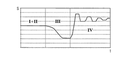
図2は、左から右へ、キュベット30を自動的に降ろすプロセスを示している。図3は、このプロセスの間、関連付けられたホールセンサ信号の変化を示している。図2の順序の第1の段階Iにおいて、輸送デバイスは既に、キュベット30が既に目標の支持位置14の上に存在するような位置に持ってこられている。クランプグリッパ11に保持されたキュベット30は、移送アーム10を矢印の方向に下げることによって、目標の支持位置14の開口部に正確に挿入され、その結果、順序の段階IIにおいて、キュベット30は、最終的に支持位置14に配置される。キュベット30が下げられ挿入される間、キュベット30の恒量(constant weight)以外に、クランプグリッパ11(およびそれに締結された磁石31)と移送アーム10(およびそれに締結されたホールセンサ32)との間の距離の変化をもたらす、クランプグリッパ11に対して有効な力は存在しない。それに応じてホールセンサは、図3に見られるように、段階IおよびIIの時間tにわたり一定の信号Sを測定する。
FIG. 2 illustrates the process of automatically lowering the cuvette 30 from left to right. FIG. 3 shows the associated Hall sensor signal changes during this process. In the first phase I of the sequence of FIG. 2, the transport device has already been brought into a position such that the cuvette 30 is already above the
図2の順序の第3の段階IIIにおいて、輸送デバイスは、矢印の方向に水平に右側へ動かされる。支持位置14内のキュベット30は、クランプグリッパ11に対して反対方向に作用し、その結果、クランプグリッパ11は偏向され、さらに移送アーム10の方向に傾く。これにより、磁石31およびホールセンサ32が取り付けられたクランプグリッパ11と移送アーム10の間の位置における距離が、測定できる程度に減少する。それに応じてホールセンサは、図3に見られるように、段階IIIの時間tにわたり信号Sの変化を測定する。
In the third stage III of the sequence in FIG. 2, the transport device is moved horizontally to the right in the direction of the arrow. The cuvette 30 in the
図2の順序の第4の段階IVにおいて、輸送デバイスは、矢印の方向にさらに水平に右側へ動かされるが、示されているのは、キュベット30がクランプグリッパ11に及ぼす力が大きくなり、クランプグリッパ11がカチッと開き、キュベット30を解放する瞬間である。クランプグリッパ11は、弾性連結要素36の回復力によって動かされて静止位置に戻り、クランプグリッパは、静止位置が設定されるまでの短い時間、旋回を続ける。それに応じて段階IVでは、クランプグリッパ11に対して有効な偏向力がなくなると、図3に見られるように、ホールセンサは信号Sの最初の急な変化を測定し、次いで、最終的に再び一定の信号が生成されるようになるまで、信号はどんどん振幅が小さくなるように変化する。
In the fourth stage IV of the sequence of FIG. 2, the transport device is moved further horizontally to the right in the direction of the arrow, but what is shown is that the force exerted by the cuvette 30 on the
図2の順序の第5の段階Vでは、降ろすプロセスは既に完了し、移送アーム10が矢印の方向に上方へ動かされ、次のキュベットを開始位置でピックアップする。
In the fifth phase V of the sequence of FIG. 2, the lowering process is already complete and the
たとえばキュベットが降ろされるときに段階IIIで予想された距離の変化が測定されず、その代わりに段階IIIでホールセンサ信号が一定のままである場合、これは、キュベットの送達に失敗し、したがって、輸送経路上でキュベットの喪失などのエラーが起こっていることを示す。 For example, if the expected change in distance at stage III is not measured when the cuvette is lowered, but instead the hall sensor signal remains constant at stage III, this will result in cuvette delivery failure and therefore Indicates that an error such as the loss of a cuvette has occurred on the transport route.
1 分析装置
2 フィードレール
3 ピペットデバイス
4 支持位置
5 インキュベーションデバイス
6 キュベットの収納容器
7 試薬容器の収納容器
8 試薬容器
9 ピペットデバイス
10 移送アーム
11 クランプグリッパ
12 測定ステーション
13 攪拌デバイス
14 支持位置
15 支持デバイス
20 制御ユニット
30 キュベット
31 磁石
32 ホールセンサ
36 可撓性の連結要素
DESCRIPTION OF SYMBOLS 1
Claims (8)
a)開始位置でクランプグリッパ(11)を水平に動かし、クランプグリッパ(11)と液体容器(30)の間にクランプ連結を生じさせる工程と;
b)クランプグリッパ(11)を持ち上げ、液体容器(30)を開始位置から取り出す工程と;
c)クランプグリッパ(11)を水平に目標位置まで動かす工程と;
d)クランプグリッパ(11)を下げ、液体容器(30)を目標位置に位置決めする工程と;
e)クランプグリッパ(11)を水平に動かし、クランプ連結を解放する工程と
を含み、ここで、
クランプグリッパ(11)と移送アーム(10)の間の距離は、少なくとも方法工程a)および/またはe)を実行する間に連続的に測定され、
i)工程a)における、開始位置でクランプグリッパ(11)と液体容器(30)の間にクランプ連結を生じさせるクランプグリッパ(11)の水平運動の間、または
ii)工程e)における、クランプ連結を解放するクランプグリッパ(11)の水平運動の間
に、クランプグリッパ(11)と移送アーム(10)の間の距離の変化が測定されなかったことが確定された場合には、液体容器(30)の輸送中にエラーが発生したことを示す信号が生成される、前記方法。 A method for monitoring the transport of a liquid container (30) using a clamp gripper (11) fastened to an automatically movable transfer arm (10) by means of a flexible coupling element (36):
a) moving the clamp gripper (11) horizontally at the starting position to create a clamp connection between the clamp gripper (11) and the liquid container (30);
b) lifting the clamp gripper (11) and removing the liquid container (30) from the starting position;
c) moving the clamp gripper (11) horizontally to the target position;
d) lowering the clamp gripper (11) and positioning the liquid container (30) at the target position;
e) moving the clamp gripper (11) horizontally to release the clamp connection, wherein:
The distance between the clamp gripper (11) and the transfer arm (10) is continuously measured at least during the execution of method steps a) and / or e);
i) during the horizontal movement of the clamp gripper (11) which causes a clamp connection between the clamp gripper (11) and the liquid container (30) in the starting position in step a), or ii) the clamp connection in step e) When it is determined that during the horizontal movement of the clamp gripper (11) releasing the distance between the clamp gripper (11) and the transfer arm (10) is not measured, the liquid container (30 ) Wherein a signal is generated indicating that an error has occurred during transport.
a)開始位置でクランプグリッパ(11)を水平に動かし、クランプグリッパ(11)と液体容器(30)の間にクランプ連結を生じさせる工程と;
b)クランプグリッパ(11)を持ち上げ、液体容器(30)を開始位置から取り出す工程と;
c)クランプグリッパ(11)を水平に目標位置まで動かす工程と;
d)クランプグリッパ(11)を下げ、液体容器(30)を目標位置に位置決めする工程と;
e)クランプグリッパ(11)を水平に動かし、クランプ連結を解放する工程と
を含み、ここで、
クランプグリッパ(11)と移送アームの間(10)の距離は、少なくとも方法工程a)および/またはe)を実行する間に連続的に測定され、
i)工程a)における、開始位置でクランプグリッパ(11)と液体容器(30)の間にクランプ連結を生じさせるクランプグリッパ(11)の水平運動の間に発生する距離の変化が、あったと決定され、第1の所定の閾値と比較され、かつ/または
ii)工程e)における、クランプ連結を解放するクランプグリッパ(11)の水平運動の間に発生する距離の変化が、あったと決定され、第2の所定の閾値と比較され;
前述の距離の変化の少なくとも1つが関連付けられた所定の閾値を下回る場合、クランプグリッパ(11)に割り当てられた交換信号が生成される、前記方法。 A method for confirming the proper functioning of a device for transporting a liquid container, including a clamp gripper (11) fastened to an automatically movable transfer arm (10) by means of a flexible connecting element (36):
a) moving the clamp gripper (11) horizontally at the starting position to create a clamp connection between the clamp gripper (11) and the liquid container (30);
b) lifting the clamp gripper (11) and removing the liquid container (30) from the starting position;
c) moving the clamp gripper (11) horizontally to the target position;
d) lowering the clamp gripper (11) and positioning the liquid container (30) at the target position;
e) moving the clamp gripper (11) horizontally to release the clamp connection, wherein:
The distance between the clamp gripper (11) and the transfer arm (10) is continuously measured at least during the execution of method steps a) and / or e),
i) In step a), it is determined that there has been a change in the distance that occurs during the horizontal movement of the clamp gripper (11) that creates a clamp connection between the clamp gripper (11) and the liquid container (30) at the starting position. And / or ii) it is determined that there has been a change in distance occurring during the horizontal movement of the clamp gripper (11) releasing the clamp connection in step e), and / or ii) Compared to a second predetermined threshold;
The method wherein an exchange signal assigned to the clamp gripper (11) is generated if at least one of the aforementioned distance changes is below an associated predetermined threshold.
液体容器を輸送するデバイスであって、
可撓性の連結要素(36)によってクランプグリッパ(11)が締結された、自動可動の移送アーム(10)、および
クランプグリッパ(11)と該移送アーム(10)の間の距離を連続的に測定する距離センサ(31、32)
を含むデバイスと、
それぞれが1つの液体容器を支持する複数の支持位置(4、14)と、
液体容器の輸送を監視する方法を制御するように構成された制御デバイスであって、該方法が:
a)開始位置(4)でクランプグリッパ(11)を水平に動かし、クランプグリッパ(11)と液体容器の間にクランプ連結を生じさせる工程と;
b)クランプグリッパ(11)を持ち上げ、液体容器を開始位置(4)から取り出す工程と;
c)クランプグリッパ(11)を水平に目標位置(14)まで動かす工程と;
d)クランプグリッパ(11)を下げ、液体容器を目標位置(14)に位置決めする工程と;
e)クランプグリッパ(11)を水平に動かし、クランプ連結を解放する工程と
を有する、制御デバイスと
を有し、ここで、
クランプグリッパ(11)と移送アーム(10)の間の距離は、少なくとも方法工程a)および/またはe)を実行する間に連続的に測定され、
i)工程a)における、開始位置(4)でクランプグリッパ(11)と液体容器の間にクランプ連結を生じさせるクランプグリッパ(11)の水平運動の間、または
ii)工程e)における、クランプ連結を解放するクランプグリッパ(11)の水平運動の間
に、クランプグリッパ(11)と移送アーム(10)の間の距離の変化が測定されなかったことが確定された場合には、液体容器の輸送中にエラーが発生したことを示す信号が生成される、前記自動分析装置。 An automatic analyzer (1),
A device for transporting a liquid container,
An automatic movable transfer arm (10), to which the clamp gripper (11) is fastened by a flexible connecting element (36), and the distance between the clamp gripper (11) and the transfer arm (10) continuously. Distance sensor to measure (31, 32)
Including a device,
A plurality of support positions (4, 14) each supporting one liquid container;
A control device configured to control a method of monitoring transport of a liquid container, the method comprising:
a) moving the clamp gripper (11) horizontally at the starting position (4) to create a clamp connection between the clamp gripper (11) and the liquid container;
b) lifting the clamp gripper (11) and removing the liquid container from the starting position (4);
c) moving the clamp gripper (11) horizontally to the target position (14);
d) lowering the clamp gripper (11) and positioning the liquid container at the target position (14);
e) moving the clamp gripper (11) horizontally and releasing the clamp connection, with a control device, wherein
The distance between the clamp gripper (11) and the transfer arm (10) is continuously measured at least during the execution of method steps a) and / or e);
i) during the horizontal movement of the clamp gripper (11) which creates a clamp connection between the clamp gripper (11) and the liquid container at the starting position (4) in step a), or ii) the clamp connection in step e) If it is determined that during the horizontal movement of the clamp gripper (11) releasing the distance change between the clamp gripper (11) and the transfer arm (10) is not measured, the transport of the liquid container The automatic analyzer, wherein a signal indicating that an error has occurred is generated.
液体容器を輸送するデバイスであって、
可撓性の連結要素(36)によってクランプグリッパ(11)が締結された、自動可動の移送アーム(10)、および
クランプグリッパ(11)と移送アーム(10)の間の距離を連続的に測定する距離センサ(31、32)
を含むデバイスと、
それぞれが1つの液体容器を支持する複数の支持位置(4、14)と、
液体容器を輸送するデバイスの適切な働きを確認する方法を制御するように構成された制御デバイスであって、該方法が:
a)開始位置(4)でクランプグリッパ(11)を水平に動かし、クランプグリッパ(11)と液体容器の間にクランプ連結を生じさせる工程と;
b)クランプグリッパ(11)を持ち上げ、液体容器を開始位置(4)から取り出す工程と;
c)クランプグリッパ(11)を水平に目標位置(14)まで動かす工程と;
d)クランプグリッパ(11)を下げ、液体容器を目標位置(14)に位置決めする工程と;
e)クランプグリッパ(11)を水平に動かし、クランプ連結を解放する工程と
を有する、制御デバイスと
を有し、ここで、
クランプグリッパ(11)と移送アーム(10)の間の距離は、少なくとも方法工程a)および/またはe)を実行する間に連続的に測定され、
i)工程a)における、開始位置(4)でクランプグリッパ(11)と液体容器の間にクランプ連結を生じさせるクランプグリッパ(11)の水平運動の間に発生する距離の変化が、あったと決定され、第1の所定の閾値と比較され、かつ/または
ii)工程e)における、クランプ連結を解放するクランプグリッパ(11)の水平運動の間に発生する距離の変化が、あったと決定され、第2の所定の閾値と比較され;
前述の距離の変化の少なくとも1つが関連付けられた所定の閾値を下回る場合、クランプグリッパ(11)に割り当てられた交換信号が生成される、前記自動分析装置。 An automatic analyzer (1),
A device for transporting a liquid container,
An automatic movable transfer arm (10) with clamp gripper (11) fastened by a flexible coupling element (36) and continuously measuring the distance between clamp gripper (11) and transfer arm (10) Distance sensor (31, 32)
Including a device,
A plurality of support positions (4, 14) each supporting one liquid container;
A control device configured to control a method for confirming proper operation of a device for transporting a liquid container, the method comprising:
a) moving the clamp gripper (11) horizontally at the starting position (4) to create a clamp connection between the clamp gripper (11) and the liquid container;
b) lifting the clamp gripper (11) and removing the liquid container from the starting position (4);
c) moving the clamp gripper (11) horizontally to the target position (14);
d) lowering the clamp gripper (11) and positioning the liquid container at the target position (14);
e) moving the clamp gripper (11) horizontally and releasing the clamp connection, with a control device, wherein
The distance between the clamp gripper (11) and the transfer arm (10) is continuously measured at least during the execution of method steps a) and / or e);
i) In step a) it is determined that there has been a change in the distance that occurs during the horizontal movement of the clamp gripper (11) that causes a clamp connection between the clamp gripper (11) and the liquid container at the start position (4). And / or ii) it is determined that there has been a change in distance occurring during the horizontal movement of the clamp gripper (11) releasing the clamp connection in step e), and / or ii) Compared to a second predetermined threshold;
Said automatic analysis device, wherein an exchange signal assigned to the clamp gripper (11) is generated if at least one of said distance changes is below an associated predetermined threshold.
Applications Claiming Priority (2)
| Application Number | Priority Date | Filing Date | Title |
|---|---|---|---|
| EP16160976.3A EP3220148B1 (en) | 2016-03-17 | 2016-03-17 | Method for monitoring the transport of liquid containers in an automatic analyzer |
| EP16160976.3 | 2016-03-17 |
Publications (2)
| Publication Number | Publication Date |
|---|---|
| JP2017167146A true JP2017167146A (en) | 2017-09-21 |
| JP6862230B2 JP6862230B2 (en) | 2021-04-21 |
Family
ID=55542601
Family Applications (1)
| Application Number | Title | Priority Date | Filing Date |
|---|---|---|---|
| JP2017050695A Active JP6862230B2 (en) | 2016-03-17 | 2017-03-16 | How to monitor the transport of liquid containers in an automated analyzer |
Country Status (3)
| Country | Link |
|---|---|
| EP (1) | EP3220148B1 (en) |
| JP (1) | JP6862230B2 (en) |
| ES (1) | ES2822926T3 (en) |
Citations (6)
| Publication number | Priority date | Publication date | Assignee | Title |
|---|---|---|---|---|
| JPH07134131A (en) * | 1993-11-12 | 1995-05-23 | Hitachi Ltd | Automatic dispensing device |
| JPH08101209A (en) * | 1994-09-30 | 1996-04-16 | Toa Medical Electronics Co Ltd | Cuvette and cuvette conveyance apparatus |
| JPH10111297A (en) * | 1996-10-07 | 1998-04-28 | Shimadzu Corp | Auto-sampler |
| US20100109360A1 (en) * | 2008-10-30 | 2010-05-06 | Canon Kabushiki Kaisha | Gripping device and system including the same |
| JP2011078969A (en) * | 2009-10-10 | 2011-04-21 | Siemens Healthcare Diagnostics Products Gmbh | Mixing apparatus of liquid sample and method |
| JP2014052376A (en) * | 2012-09-06 | 2014-03-20 | Siemens Healthcare Diagnostics Products Gmbh | Adjustment system for transfer system in in-vitro diagnostic system |
Family Cites Families (3)
| Publication number | Priority date | Publication date | Assignee | Title |
|---|---|---|---|---|
| US5945798A (en) * | 1998-08-27 | 1999-08-31 | Eastman Kodak Company | System for determining part presence and grip pressure for a robotic gripping device |
| WO2004067233A1 (en) * | 2003-01-31 | 2004-08-12 | Thermo Crs Ltd. | A gripping error detection mechanism for robot gripper |
| WO2013018213A1 (en) * | 2011-08-03 | 2013-02-07 | 株式会社安川電機 | Positional displacement detector, robot hand, and robot system |
-
2016
- 2016-03-17 ES ES16160976T patent/ES2822926T3/en active Active
- 2016-03-17 EP EP16160976.3A patent/EP3220148B1/en active Active
-
2017
- 2017-03-16 JP JP2017050695A patent/JP6862230B2/en active Active
Patent Citations (6)
| Publication number | Priority date | Publication date | Assignee | Title |
|---|---|---|---|---|
| JPH07134131A (en) * | 1993-11-12 | 1995-05-23 | Hitachi Ltd | Automatic dispensing device |
| JPH08101209A (en) * | 1994-09-30 | 1996-04-16 | Toa Medical Electronics Co Ltd | Cuvette and cuvette conveyance apparatus |
| JPH10111297A (en) * | 1996-10-07 | 1998-04-28 | Shimadzu Corp | Auto-sampler |
| US20100109360A1 (en) * | 2008-10-30 | 2010-05-06 | Canon Kabushiki Kaisha | Gripping device and system including the same |
| JP2011078969A (en) * | 2009-10-10 | 2011-04-21 | Siemens Healthcare Diagnostics Products Gmbh | Mixing apparatus of liquid sample and method |
| JP2014052376A (en) * | 2012-09-06 | 2014-03-20 | Siemens Healthcare Diagnostics Products Gmbh | Adjustment system for transfer system in in-vitro diagnostic system |
Also Published As
| Publication number | Publication date |
|---|---|
| EP3220148A1 (en) | 2017-09-20 |
| EP3220148B1 (en) | 2020-07-15 |
| JP6862230B2 (en) | 2021-04-21 |
| ES2822926T3 (en) | 2021-05-05 |
Similar Documents
| Publication | Publication Date | Title |
|---|---|---|
| JP5886412B2 (en) | Container holder and container carrier | |
| EP2096446B1 (en) | Automatic analyzer | |
| EP2746736B1 (en) | System for managing of bulk liquids and/or solids | |
| WO2013065528A1 (en) | Automated analysis system | |
| JP6320535B2 (en) | Automatic analyzer | |
| JPWO2015111526A1 (en) | Automatic analyzer | |
| JP2014516403A5 (en) | ||
| US20100105143A1 (en) | Sample analyzer, sample analyzing method, and computer program product | |
| JP4948020B2 (en) | Liquid quality control method and automatic analyzer for analysis support of automatic analyzer | |
| JP6362737B2 (en) | Transporting liquid containers in automated analyzers | |
| JP2014178311A (en) | Automatic analyzer and reagent container | |
| US10227973B2 (en) | Method for checking the functionality of a metering pump | |
| CN106443038B (en) | Pipetting device with two temperature sensors | |
| JP6991363B2 (en) | Automatic analyzer | |
| JP6862230B2 (en) | How to monitor the transport of liquid containers in an automated analyzer | |
| WO2016136390A1 (en) | Automatic analysis apparatus | |
| US10359438B2 (en) | Warning system for potentially erroneous measurement results in an automated analyzer | |
| JP6594922B2 (en) | Method for mixing liquids in an automated analyzer | |
| JP6768870B2 (en) | Laboratory analysis system with improved sample pipetting | |
| JP6675226B2 (en) | Automatic analyzer | |
| JP4557995B2 (en) | Automatic analyzer | |
| WO2023007883A1 (en) | Specimen pretreatment device and pooled specimen test method | |
| JP6687501B2 (en) | Method for transferring liquid volume in an analyzer | |
| US20230168268A1 (en) | Leakage test |
Legal Events
| Date | Code | Title | Description |
|---|---|---|---|
| A621 | Written request for application examination |
Free format text: JAPANESE INTERMEDIATE CODE: A621 Effective date: 20200309 |
|
| A977 | Report on retrieval |
Free format text: JAPANESE INTERMEDIATE CODE: A971007 Effective date: 20210224 |
|
| TRDD | Decision of grant or rejection written | ||
| A01 | Written decision to grant a patent or to grant a registration (utility model) |
Free format text: JAPANESE INTERMEDIATE CODE: A01 Effective date: 20210302 |
|
| A61 | First payment of annual fees (during grant procedure) |
Free format text: JAPANESE INTERMEDIATE CODE: A61 Effective date: 20210331 |
|
| R150 | Certificate of patent or registration of utility model |
Ref document number: 6862230 Country of ref document: JP Free format text: JAPANESE INTERMEDIATE CODE: R150 |
|
| R250 | Receipt of annual fees |
Free format text: JAPANESE INTERMEDIATE CODE: R250 |