JP2017166573A - Shock absorber - Google Patents
Shock absorber Download PDFInfo
- Publication number
- JP2017166573A JP2017166573A JP2016052353A JP2016052353A JP2017166573A JP 2017166573 A JP2017166573 A JP 2017166573A JP 2016052353 A JP2016052353 A JP 2016052353A JP 2016052353 A JP2016052353 A JP 2016052353A JP 2017166573 A JP2017166573 A JP 2017166573A
- Authority
- JP
- Japan
- Prior art keywords
- cylinder
- chamber
- air chamber
- rod
- air
- Prior art date
- Legal status (The legal status is an assumption and is not a legal conclusion. Google has not performed a legal analysis and makes no representation as to the accuracy of the status listed.)
- Granted
Links
- 230000035939 shock Effects 0.000 title claims abstract description 94
- 239000006096 absorbing agent Substances 0.000 title claims abstract description 92
- 239000007788 liquid Substances 0.000 claims abstract description 79
- 230000006837 decompression Effects 0.000 claims description 2
- 238000007654 immersion Methods 0.000 abstract 1
- 230000006835 compression Effects 0.000 description 17
- 238000007906 compression Methods 0.000 description 17
- 238000013016 damping Methods 0.000 description 10
- 239000003921 oil Substances 0.000 description 10
- 230000008602 contraction Effects 0.000 description 9
- 239000002131 composite material Substances 0.000 description 7
- 230000008859 change Effects 0.000 description 6
- 239000010720 hydraulic oil Substances 0.000 description 6
- 230000007423 decrease Effects 0.000 description 5
- 230000002093 peripheral effect Effects 0.000 description 5
- 230000000903 blocking effect Effects 0.000 description 4
- 238000004891 communication Methods 0.000 description 4
- 229920001971 elastomer Polymers 0.000 description 4
- 238000005192 partition Methods 0.000 description 4
- 230000000694 effects Effects 0.000 description 3
- 238000007789 sealing Methods 0.000 description 3
- 239000000806 elastomer Substances 0.000 description 2
- 230000009545 invasion Effects 0.000 description 2
- 239000002184 metal Substances 0.000 description 2
- 238000012986 modification Methods 0.000 description 2
- 230000004048 modification Effects 0.000 description 2
- 230000035515 penetration Effects 0.000 description 2
- 239000000725 suspension Substances 0.000 description 2
- 239000013585 weight reducing agent Substances 0.000 description 2
- 238000009825 accumulation Methods 0.000 description 1
- 238000013459 approach Methods 0.000 description 1
- 238000005452 bending Methods 0.000 description 1
- 125000004122 cyclic group Chemical group 0.000 description 1
- 230000000593 degrading effect Effects 0.000 description 1
- 230000002542 deteriorative effect Effects 0.000 description 1
- 238000010586 diagram Methods 0.000 description 1
- 230000002349 favourable effect Effects 0.000 description 1
- 239000012530 fluid Substances 0.000 description 1
- 239000006260 foam Substances 0.000 description 1
- 238000004519 manufacturing process Methods 0.000 description 1
- 230000000116 mitigating effect Effects 0.000 description 1
- 230000000149 penetrating effect Effects 0.000 description 1
- 230000004044 response Effects 0.000 description 1
- 230000004043 responsiveness Effects 0.000 description 1
Images

Abstract
Description
本発明は、緩衝器に関する。 The present invention relates to a shock absorber.
従来、二輪車又は三輪車等の鞍乗型車両に用いられる緩衝器の中には、軽量化を目的として、懸架ばねを金属製のコイルばねに代えて気体ばねにしたものがある。 2. Description of the Related Art Conventionally, some shock absorbers used in straddle-type vehicles such as two-wheeled vehicles or three-wheeled vehicles have a suspension spring replaced with a metal coil spring for the purpose of weight reduction.
このような気体ばねを利用する緩衝器は、例えば、シリンダと、シリンダ内に移動可能に挿入されるロッドと、シリンダから外方へ突出するロッドの端部に連結されて、ロッドとの間に気室を形成する管状部材とを備えている(例えば、特許文献1)。そして、当該緩衝器では、気室内に高圧の気体を封入しており、緩衝器が伸縮すると、気室容積が拡縮されて、緩衝器の伸縮度合いに応じた弾性力を得られる。また、緩衝器のシリンダ内には、ピストンで区画される二つの部屋が形成されており、それぞれの部屋に作動油が充填されている。そして、緩衝器が伸縮すると、ピストンで一方の部屋を圧縮するとともに他方の部屋を拡大し、両者に差圧を生じさせて減衰力を発揮する。 A shock absorber using such a gas spring is connected to, for example, a cylinder, a rod movably inserted into the cylinder, and an end of a rod protruding outward from the cylinder. And a tubular member that forms an air chamber (for example, Patent Document 1). In the shock absorber, high-pressure gas is sealed in the air chamber. When the shock absorber expands and contracts, the air chamber volume is expanded and contracted, and an elastic force corresponding to the degree of expansion and contraction of the shock absorber can be obtained. Also, two chambers defined by pistons are formed in the cylinder of the shock absorber, and each chamber is filled with hydraulic oil. When the shock absorber expands and contracts, the piston compresses one of the chambers and expands the other chamber to generate a differential pressure between the two chambers and exert a damping force.
さらに、上記緩衝器は、シリンダに連結されてロッドを摺動自在に軸支する環状のロッドガイドを備えており、このロッドガイドの内周にロッドの外周に摺接するオイルシールを設けるとともに、ロッドガイドの内周であってオイルシールよりも気室側にロッドの外周に摺接するエアシールを設けている。当該構成によれば、緩衝器が収縮して気室内の圧力が高くなったとしても、気室内の圧力がオイルシールに作用するのをエアシールで防止できる。よって、気室内の圧力を受けてオイルシールが開き、気室内の気体がシリンダ内に侵入するのを防止できる。 Further, the shock absorber includes an annular rod guide that is coupled to the cylinder and pivotally supports the rod, and an oil seal that is in sliding contact with the outer periphery of the rod is provided on the inner periphery of the rod guide. An air seal that is slidably in contact with the outer periphery of the rod is provided on the inner periphery of the guide and closer to the air chamber than the oil seal. According to this configuration, even if the shock absorber contracts and the pressure in the air chamber increases, the air seal can prevent the pressure in the air chamber from acting on the oil seal. Therefore, the oil seal is opened by receiving the pressure in the air chamber, and the gas in the air chamber can be prevented from entering the cylinder.
ここで、上記気体ばねを備えた緩衝器が伸長する場合、ロッドがシリンダから退出する際に、ロッドの外周に付着した作動油のほとんどはオイルシールで掻き落とされるが、オイルシールを通過したロッドの外周には薄く油膜が形成されている。そして、ロッドがエアシールを通過する際に、非常にわずかではあるが、ロッドの外周に付着した油膜の一部がエアシールで掻き落とされてエアシールとオイルシールとの間の空間に溜まることがある。さらに、ロッドがシリンダ内に進入する緩衝器の収縮時に、空間内の作動油がオイルシールで掻き落とされて空間内に取り残されると、緩衝器が長期間に亘って伸縮を繰り返した場合、空間内に作動油が蓄積されて、空間内の圧力が高圧となってしまう場合がある。 Here, when the shock absorber with the gas spring is extended, most of the hydraulic oil adhering to the outer periphery of the rod is scraped off by the oil seal when the rod retracts from the cylinder, but the rod that has passed through the oil seal A thin oil film is formed on the outer periphery of the film. When the rod passes through the air seal, a small amount of the oil film adhering to the outer periphery of the rod may be scraped off by the air seal and collected in the space between the air seal and the oil seal. Furthermore, when the shock absorber that the rod enters into the cylinder contracts, if the hydraulic oil in the space is scraped off by the oil seal and left in the space, In some cases, hydraulic oil accumulates in the interior and the pressure in the space becomes high.
このように、上記空間が作動油の蓄積によって高圧になると、気室側からの圧力を受けるエアシールに当該エアシールの背面となる空間側から高圧が作用して、エアシールのシール性を悪化させ、シリンダ内へ気室内の気体が侵入する可能性がある。そして、シリンダ内へ気体が侵入すると、緩衝器の減衰力発生の応答性が低下するので好ましくない。 As described above, when the space becomes high pressure due to the accumulation of hydraulic oil, high pressure acts on the air seal that receives pressure from the air chamber side from the space side that is the back surface of the air seal, thereby degrading the sealing performance of the air seal, There is a possibility that gas inside the air chamber may enter the inside. And if gas enters the cylinder, it is not preferable because the response of the damping force generation of the shock absorber is lowered.
そこで、本発明は、気体ばねを備えていても、シリンダ内への気体の侵入を防止できる緩衝器の提供を目的とする。 Then, even if it has a gas spring, this invention aims at provision of the buffer which can prevent the penetration | invasion of the gas into a cylinder.
上記課題を解決する請求項1に記載の発明は、内部に液体が収容される作動室が形成されるシリンダ内に移動可能に挿入されるロッドと、前記ロッドに連結されて内側に前記シリンダが移動可能に挿入されるエアシリンダと、前記シリンダに連結されて前記ロッドを移動自在に支えるとともに、前記エアシリンダ内を気体が封入される前記ロッド側の第一気室と前記シリンダ側の第二気室とに区画する環状のロッドガイドと、前記ロッドガイドの内周に設けられる液体用シール及び気体用シールと、前記ロッドガイドの内周であって前記液体用シールと前記気体用シールとの間にできる空間を前記第二気室へ連通する圧抜通路と、前記圧抜通路に設けられ、前記空間から前記第二気室へ向かう液体の流れのみを許容する弁とを備える。このため、空間から第二気室へ圧力を逃がせるので、空間内が高圧になるのを防止して、気体用シールの背面に高圧が作用して、気体用シールのシール性が低下するのを防止できる。
The invention according to
本発明の緩衝器によれば、気体ばねを備えていても、シリンダ内への気体の侵入を防止できる。 According to the shock absorber of the present invention, the gas can be prevented from entering the cylinder even if the gas spring is provided.
以下に本発明の実施の形態について、図面を参照しながら説明する。いくつかの図面を通して付された同じ符号は、同じ部品を示す。 Embodiments of the present invention will be described below with reference to the drawings. The same reference numerals used throughout the several drawings indicate the same parts.
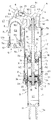
図1に示す本発明の一実施の形態に係る緩衝器Aは、二輪車又は三輪車等の鞍乗型車両に搭載されて、車体の骨格となるフレームと、このフレームの後部に揺動自在に連結されて、後輪を支えるスイングアームとの間に介装されるリヤクッションユニットユニットである。 A shock absorber A according to an embodiment of the present invention shown in FIG. 1 is mounted on a straddle-type vehicle such as a two-wheeled vehicle or a three-wheeled vehicle, and is swingably connected to a frame serving as a skeleton of the vehicle body and a rear portion of the frame. The rear cushion unit unit is interposed between the swing arm that supports the rear wheel.
緩衝器Aは、シリンダ1と、シリンダ1内に摺動自在に挿入されるピストン2と、図1中下端がピストン2に連結されて上端がシリンダ1外へ延びるロッド3と、シリンダ1の図1中上側開口を塞ぎ、ロッド3が貫通する環状のロッドガイド10と、シリンダ1の図1中下側開口を塞ぐボトムキャップ11と、横並びに設けられた有底筒状のホルダ部4とハウジング部5とを有し、ホルダ部4の底部4aにシリンダ1外へ突出するロッド3の図1中上端が連結されるホルダハウジング複合部材Hと、ハウジング部5内に収容される有底筒状のブラダ50と、ブラダ50及びハウジング部5の開口を塞ぐキャップ51と、ホルダハウジング複合部材Hにおけるホルダ部4とハウジング部5との間に取り付けられるベースバルブアッセンブリ6と、ホルダ部4の筒部4bに連結されて筒部4bから図1中下方へ延び、内側にシリンダ1が出入りする外筒7と、外筒7に連結されて外筒7から図1中下方へ延びる環状の延長部材8とを備える。
The shock absorber A includes a
そして、シリンダ1、ピストン2、及びロッド3を有してテレスコピック型のダンパ本体Dが構成される。また、ホルダハウジング複合部材Hのハウジング部5、ブラダ50、及びキャップ51を有してリザーバRが構成され、リザーバR内はダンパ本体D内に通じている。そして、ダンパ本体Dと、ベースバルブアッセンブリ6と、リザーバRとを備えてダンパが構成される。また、ホルダハウジング複合部材Hのホルダ部4、外筒7、延長部材8を有してエアシリンダCが構成されており、エアシリンダCとダンパ本体Dとの間に気体が封入されて、気体ばねが構成されている。
A telescopic damper main body D is configured by including the
さらに、緩衝器Aの軸方向の両端となるホルダ部4の図1中上部とボトムキャップ11の図1中下部には、それぞれブラケット4c,11aが設けられている。そして、ブラケット4cが車体に連結され、ブラケット11aがリンク等を介してスイングアームに連結される。このため、路面凹凸による衝撃が車輪に入力されると、ロッド3がシリンダ1に出入りしてダンパ本体Dが伸縮するとともに、シリンダ1がエアシリンダCに出入りして気体ばねが伸縮し、その結果、緩衝器Aが伸縮する。なお、本発明に係る緩衝器の用途はリヤクッションユニットに限られず、適宜変更できる。
Further,
以下、緩衝器Aを構成する各部材について説明する。 Hereinafter, each member constituting the shock absorber A will be described.
シリンダ1は、筒状であり、図1中上下に延びて、その両端部内周に螺子溝が形成されている。そして、シリンダ1の図1中上端部にロッドガイド10が螺合され、下端部にボトムキャップ11が螺合される。そして、シリンダ1、ロッドガイド10、及びボトムキャップ11で囲われる空間が作動室Lであり、作動室Lは、ピストン2で二つの部屋に区画されている。これら二つの部屋のうち、緩衝器Aの伸長時に圧縮されるロッド3側の部屋を伸側室L1とし、収縮時に圧縮されるピストン2側の部屋を圧側室L2とする。これら伸側室L1と圧側室L2には、それぞれ作動油等の液体が満たされている。
The
ロッドガイド10は、図2に示すように、シリンダ1内に挿入される小径部10aと、小径部10aの図2中上側に連なり、外径が小径部10aの外径よりも大きいピストン部10bとを有しており、ピストン部10bがシリンダ1から径方向外方へ突出する。ピストン部10bは、外筒7の内周に摺接し、エアシリンダCの内部をロッド3側の第一気室G1と、シリンダ1側の第二気室G2に区画する。これらについては、後に詳細に説明する。
As shown in FIG. 2, the
また、ロッドガイド10の内周には、環状のブッシュ12が設けられ、ロッドガイド10は、ブッシュ12を介してロッド3の外周に摺接し、ロッド3を軸方向移動自在に支える。また、ロッドガイド10の内周であってブッシュ12の上側には、ロッド3の外周に摺接し、第一気室G1の気体がシリンダ1内へ侵入するのを防ぐ環状の気体用シール13が設けられ、ブッシュ12の下側には、ロッド3の外周に摺接し、シリンダ1内の液体がシリンダ1外へ流出するのを防ぐ環状の液体用シール14が設けられている。また、ロッドガイド10の小径部10aとシリンダ1との間、及びボトムキャップ11(図1)とシリンダ1との間が、それぞれ符示しないシールで塞がれている。よって、作動室Lが液密に維持される。
An
また、ロッドガイド10には、ロッド3の外周であって、ロッドガイド10、気体用シール13、及び液体用シール14で囲われる空間Kを第二気室G2に連通する圧抜通路10cが形成されるとともに、この圧抜通路10cを空間Kから第二気室G2へ向かう液体の流れのみを許容するチェックバルブ19が設けられている。このチェックバルブ19は、弁体を弁座に着座させることで圧抜通路10cを遮断するが、弁体を弁座に着座させた状態で弁体と弁座との間がシールされるようになっており、第二気室G2内の気体が空間Kへ移動するのを防止する。
Further, the
さらに、ロッドガイド10の図2中下端部内周には、環状の閉塞部材15と、環状のリバウンドクッション16が設けられている。閉塞部材15は、断面逆L字状に形成されていて、ロッド3の外周に摺接する。リバウンドクッション16は、ゴム等のエラストマーで形成されて、弾性を有する。また、リバウンドクッション16は、閉塞部材15におけるロッド3の外周に摺接する部分の外周に設けられるとともに、ロッドガイド10と閉塞部材15で背面を支えられている。そして、ロッド3がシリンダ1から所定量退出すると、ロッド3の外周に固定されたバルブストッパ23がリバウンドクッション16に当接し、リバウンドクッション16が弾性変形して緩衝器Aの最伸長時の衝撃を緩和する。
Further, an
ロッド3は、図1に示すように、ロッドガイド10で支えられる本体部3aと、本体部3aの図1中下側に連なりシリンダ1内に配置されるとともに、外径が本体部3aの外径よりも小さい取付部3bと、本体部3aの図1中上側に連なりシリンダ1外に配置されるとともに、外周に螺子溝が形成される連結部3cとを有する。そして、連結部3cがホルダ部4に連結されるとともに、本体部3aが外筒7とロッドガイド10の内側を通り、取付部3bの外周に環状のピストン2が装着されている。より詳しくは、取付部3bの先端部外周には、螺子溝が形成されており、この先端部の外周に螺合するナット30と、取付部3bの末端にできる段差との間にピストン2が挟まれて固定される。
As shown in FIG. 1, the rod 3 is arranged in the
また、ロッド3には、中心部を軸方向に貫通する縦孔3dと、本体部3aにおける取付部3b近くの側方に開口し、縦孔3dに通じる横孔3eが形成されている。横孔3eは、緩衝器Aの最伸長時に閉塞部材15で塞がれるようになっており、通常のストローク範囲では、伸側室L1に連通する。また、縦孔3dは、常に圧側室L2と連通するので、横孔3eが閉塞されていない通常のストローク範囲では、液体がロッド3内を通って伸側室L1と圧側室L2との間を移動できる。つまり、縦孔3dと横孔3eは、ピストン2に積層される後述の伸側バルブ20及び圧側バルブ21を迂回するバイパス路を構成し、このバイパス路は、緩衝器Aの最伸長時に閉塞部材15で遮断される。さらに、横孔3eは、絞りとして機能し、伸側室L1と圧側室L2との間を移動する液体の流れに抵抗を与える。
Further, the rod 3 is formed with a
ピストン2には、伸側室L1と圧側室L2とを連通する伸側通路2aと圧側通路2bが形成される。また、ピストン2の図1中下側に、伸側通路2aの出口を開閉する上記伸側バルブ20が積層され、ピストン2の図1中上側に、圧側通路2bの出口を開閉する上記圧側バルブ21が積層されている。伸側バルブ20及び圧側バルブ21は、ともにリーフバルブであり、外周側の撓みが許容された状態で、内周部をピストン2とともにロッド3の外周にナット30で固定される。よって、伸側バルブ20は、伸側室L1の圧力を受けて撓むと伸側通路2aを開放でき、圧側バルブ21は、圧側室L2の圧力を受けて撓むと圧側通路2bを開放できる。なお、伸側バルブ20及び圧側バルブ21は、リーフバルブに限られず、ポペット弁又はオリフィス等、適宜変更できる。
The
また、伸側バルブ20の図1中下側と、圧側バルブ21の上側には、それぞれバルブストッパ22,23が積層されている。バルブストッパ22,23は、それぞれに対応する伸側バルブ20又は圧側バルブ21が所定量撓むとバルブの背面に当接し、それ以上バルブが撓むのを防止してバルブの開口量を制限する。また、バルブストッパ23は、リバウンドストッパを兼ねており、前述のように、緩衝器Aの最伸長時にリバウンドクッション16に突き当たる。
Further,
つづいて、ロッド3の図1中上端に連結されるホルダハウジング複合部材Hは、有底筒状で、開口を図1中下方へ向けて配置されるホルダ部4と、このホルダ部4と横並びに設けられ、有底筒状で、開口を図1中下方へ向けて配置されるハウジング部5と、ホルダ部4とハウジング部5を繋ぐ接続部9とを有する。前述のように、ホルダ部4はエアシリンダCの一部であり、ハウジング部5はリザーバRの一部である。また、ホルダハウジング複合部材Hには、縦孔3dを通じて作動室LとリザーバR内を連通する液体用通路90と、エアシリンダC内とリザーバR内を連通する気体用通路91が形成されている。さらに、接続部9には、ベースバルブアッセンブリ6が取り付けられていて、液体用通路90を流れる液体は、ベースバルブアッセンブリ6を介して作動室LとリザーバRとの間を移動する。
Subsequently, the holder housing composite member H connected to the upper end of the rod 3 in FIG. 1 is a bottomed cylindrical shape, and the holder portion 4 is arranged with the opening facing downward in FIG. 1 and includes a
また、ハウジング部5には、有底筒状で拡縮可能なブラダ50が、底部をハウジング部5の底部へ向けて挿入されている。そして、ハウジング部5の筒部の開口端部にキャップ51が装着されており、このキャップ51でブラダ50の開口端部をハウジング部5に固定するとともに、ブラダ50の開口を塞ぐ。ハウジング部5の内部には、ブラダ50とハウジング部5との間に液体が充填される液室L3が形成されるとともに、ブラダ50の内側に気体が封入される気室G3が形成されている。このように、リザーバRは、ダンパ本体Dの外部に設けた別置き型のタンクであり、ブラダ50で区画される液室L3と気室G3を有する。なお、リザーバRにおいて、液室L3と気室G3を区画する部材は、ブラダ50に限らず、フリーピストン又はベローズ等であってもよい。
Further, a
リザーバRの液室L3は、液体用通路90と、ロッド3の縦孔3dを通じて作動室Lに連通し、気室G3は、気体用通路91を通じて第一気室G1に連通する。より詳しくは、キャップ51は、有底筒状に形成されていて、底部51aをハウジング部5の開口側に向けるとともに、筒部51bをハウジング部5の内方へ向けてハウジング部5内に挿入されている。そして、筒部51bの先端部外周にブラダ50が連結されている。また、キャップ51の筒部51bには、当該筒部51bの肉厚を貫通する複数の貫通孔51cが周方向に並んで形成されている。ハウジング部5の内周で、貫通孔51cの開口に対向する部分には、周方向に沿う環状溝5aが形成されており、この環状溝5aの内側に気体用通路91が開口する。また、ハウジング部5における環状溝5aよりも外気側の外周が、シール52で塞がれる。よって、第一気室G1内の気体は、気体用通路91と、環状溝5aによりハウジング部5とキャップ51との間にできる隙間と、貫通孔51cをこの順に通って気室G3内へ移動でき、気室G3内の気体も上記通路を逆に通って第一気室G1内へ移動できる。
The liquid chamber L3 of the reservoir R communicates with the working chamber L through the
また、接続部9に設けたベースバルブアッセンブリ6は、液体用通路90の途中に設けられ、作動室Lと液室L3を区画する図示しない隔壁と、この隔壁に形成されて作動室Lと液室L3とを連通する吸込通路6a及び排出通路6bと、吸込通路6aを液室L3から作動室Lへ向かう液体の流れのみを許容するチェックバルブ60と、排出通路6bを作動室Lから液室L3へ向かう液体の流れに抵抗を与えるとともに、反対方向の流れを阻止する減衰バルブ61とを備える。
In addition, the
また、ホルダ部4は、図1に示すように、底部4aと、この底部4aの外周部から一方へ延びる筒部4bとを有し、筒部4bの先端部内周に外筒7が螺合される。筒部4bは、底部4a側の外径が外筒7の外径よりも小さくなっている。そして、底部4aの図1中上方に、ブラケット4cが設けられており、当該ブラケット4cが車体に連結される。筒部4bの小径な部分は、ロッドガイド10が摺接しない部分であって、内径をロッドガイド10が摺接する外筒7の内径よりも小さくできるので、外径を外筒7の外径よりも小さくできる。このように、エアシリンダCにおいて、ロッドガイド10が摺接しない部分の外径を摺接部の外径よりも小さくすると、摺動部、即ち、外筒7の外径を大きくしたとしても、緩衝器Aを車体に取り付ける際、緩衝器Aと車体との干渉を避けられるとともに、取付を容易にできる。
Further, as shown in FIG. 1, the holder part 4 has a bottom part 4a and a cylindrical part 4b extending from the outer peripheral part of the bottom part 4a to one side, and the
また、底部4aの図1中下方には、筒部4bの内側へ突出する環状のナット部4dが設けられている。このナット部4dの内周にロッド3が螺合されており、ロッド3は、ロックナット31の利用により緩み止めされている。さらに、ロッド3の外周には、ロックナット31の下側にバンプクッション32が取り付けられている。バンプクッション32は、ゴム等のエラストマーで形成されて弾性を有し、ロッド3がシリンダ1に所定量進入すると、ロッドガイド10に当接し、弾性変形して緩衝器Aの最収縮時の衝撃を緩和する。
Further, an annular nut portion 4d that protrudes inward of the cylindrical portion 4b is provided below the bottom portion 4a in FIG. A rod 3 is screwed onto the inner periphery of the nut portion 4 d, and the rod 3 is prevented from loosening by using a lock nut 31. Further, a
つづいて、外筒7は、図1中上下に延びており、上端部外周と、下端部外周に螺子溝が形成される。そして、外筒7は、図1中上端部がホルダ部4の内周に螺合され、図1中下端部が延長部材8の内周に螺合されており、外筒7の内周にロッドガイド10のピストン部10bが摺接する。ピストン部10bの外周には、図2に示すように、環状のブッシュ17が設けられ、ロッドガイド10は、ブッシュ17を介して外筒7の内周に摺接する。また、ピストン部10bの外周にはブッシュ17と縦並びに外筒7の内周に摺接する環状のシール18が設けられ、ロッドガイド10と外筒7との間がシール18で塞がれるとともに、外筒7とホルダ部4との間がシール70(図1)で塞がれる。そして、ロッド3の外周であって、ホルダ部4、外筒7、及びロッドガイド10で囲われる空間にエア等の気体が封入されており、当該部分が第一気室G1となっていて、気密に維持されている。
Subsequently, the
緩衝器Aが収縮する場合、エアシリンダC内にシリンダ1が進入し、ロッドガイド10に対してエアシリンダCが下降するので、ロッドガイド10で第一気室G1内の気体が圧縮されて、第一気室G1内の圧力が高くなる。反対に、緩衝器Aが伸長する場合、エアシリンダCからシリンダ1が退出し、ロッドガイド10に対してエアシリンダCが上昇するので、第一気室G1の容積が拡大して第一気室G1内の圧力が低くなる。このように、ロッドガイド10は第一気室G1内の気体を圧縮するエアピストンとして機能し、エアシリンダC、ロッドガイド10、第一気室G1を有して気体ばねであるメインばねS1が構成される。メインばねS1の弾性力は、緩衝器Aが収縮して第一気室G1内の圧力が上昇するほど大きくなり、メインばねS1は、ダンパ本体Dを伸長方向へ附勢して、車体を弾性支持する懸架ばねとして機能する。
When the shock absorber A contracts, the
前述のように、第一気室G1は、気体用通路91を通じて気室G3に連通している。このため、第一気室G1内の圧力と気室G3内の圧力は等しく、当該気室G3も第一気室G1とともにメインばねS1を構成する。また、図示しないが、気体用通路91には、接続部9の外方へ開口する気体給排路が接続されており、この気体給排路の開口端にエアバルブが取り付けられている。よって、エアバルブを介して第一気室G1及び気室G3内に気体を給排し、これらの圧力を同時に変更できるとともに、メインばねS1の弾性力を調整できる。
As described above, the first air chamber G1 communicates with the air chamber G3 through the
つづいて、延長部材8は、図2に示すように、シリンダ1の挿通を許容する環状の底部8aと、底部8aの外周部から図2中上方へ延びる筒部8bとを有し、筒部8bの先端部が外筒7の外周に螺合されている。底部8aの内周には、環状のブッシュ80が設けられ、延長部材8がブッシュ80を介してシリンダ1の外周に摺接する。さらに、底部8aの内周であってブッシュ80の図2中下方にシリンダ1の外周に摺接する環状のシール81,82が設けられ、延長部材8とシリンダ1との間がシール81,82で塞がれるとともに、外筒7と延長部材8との間がシール83で塞がれる。そして、シリンダ1の外周であって、外筒7、延長部材8、及びロッドガイド10のピストン部10bで囲われる空間にエア等の気体が封入されており、当該部分が第二気室G2となっていて、気密に維持されている。
Subsequently, as shown in FIG. 2, the extending
緩衝器Aが収縮する場合、エアシリンダC内にシリンダ1が進入し、ロッドガイド10に対してエアシリンダCが下降するので、第二気室G2の容積が拡大して第二気室G2内の圧力が低くなる。反対に、緩衝器Aが伸長する場合、エアシリンダCからシリンダ1が退出し、ロッドガイド10に対してエアシリンダCが上昇するので、ピストン部10bで第二気室G2内の気体が圧縮されて、第二気室G2内の圧力が高くなる。このように、ロッドガイド10のピストン部10bは第二気室G2内の気体を圧縮するエアピストンとして機能し、エアシリンダC、ロッドガイド10、第二気室G2を有して気体ばねであるバランスばねS2が構成される。このバランスばねS2の弾性力は、緩衝器Aが伸長して第二気室G2内の圧力が上昇するほど大きくなり、バランスばねS2は、メインばねS1とは反対に、ダンパ本体Dを収縮方向へ附勢する。
When the shock absorber A contracts, the
また、延長部材8には、底部8aを斜めに貫通する気体給排路8c(図2)が形成されるとともに、気体給排路8cにエアバルブ84が取り付けられている。よって、エアバルブ84を介して第二気室G2に気体を給排し、第二気室G2内の圧力を変更できるとともに、バランスばねS2の弾性力を調整できる。さらに、エアバルブ84は、その先端が延長部材8の底部8aから図2中上方へ突出し、第二気室G2内に突出するように配置されている。
The
このように、緩衝器Aは、ダンパ本体Dを附勢する方向が逆向きになるメインばねS1とバランスS2ばねを備えているので、緩衝器Aを車両に搭載した場合、車両の乗り心地を良好にできる。より詳しくは、メインばねS1のみでも車体を弾性支持できるものの、このようにすると、緩衝器全体のばね特性がメインばねS1のみの特性となる。メインばねS1は気体ばねであるので、ばね特性は、非線形特性となる。そして、当該緩衝器のばね特性を最収縮側となるストローク後半の所望の特性に合わせて設定すると、ストローク前半の、特に、最伸長時近傍の弾性力が過剰となって、乗り心地を悪化させる虞がある。そこで、バランスばねS2を追加して、緩衝器Aにおける最伸長時近傍の収縮を助けるようにすると、車両の乗り心地を良好にできる。特に、車両の乗り心地を良好にする上では、緩衝器Aが最伸長時にあるときのメインばねS1の伸長方向に作用する弾性力をバランスばねS2で相殺し、メインばねS1のばね特性とバランスばねS2のばね特性の合成の特性を、ストローク量に対して比例する比例特性に近づけて、コイルばねの特性と近似させるのが好ましい。 As described above, the shock absorber A includes the main spring S1 and the balance S2 spring in which the direction in which the damper main body D is biased is reversed. Therefore, when the shock absorber A is mounted on the vehicle, the ride comfort of the vehicle is improved. Can be good. More specifically, although the vehicle body can be elastically supported only by the main spring S1, the spring characteristic of the entire shock absorber becomes the characteristic of only the main spring S1. Since the main spring S1 is a gas spring, the spring characteristic is a non-linear characteristic. And if the spring characteristic of the shock absorber is set in accordance with the desired characteristic of the second half of the stroke on the most contracted side, the elastic force in the first half of the stroke, particularly in the vicinity of the maximum extension, becomes excessive, thereby deteriorating riding comfort. There is a fear. Therefore, if the balance spring S2 is added to assist the contraction of the shock absorber A in the vicinity of the maximum extension, the riding comfort of the vehicle can be improved. In particular, in order to improve the ride comfort of the vehicle, the elastic force acting in the extension direction of the main spring S1 when the shock absorber A is at its maximum extension is offset by the balance spring S2, and the balance with the spring characteristics of the main spring S1. It is preferable to approximate the combined characteristic of the spring characteristic of the spring S2 to the characteristic of the coil spring by making it close to a proportional characteristic proportional to the stroke amount.
以下、本実施の形態に係る緩衝器Aの作動について説明する。 Hereinafter, the operation of the shock absorber A according to the present embodiment will be described.
ロッド3がシリンダ1から退出するとともに、シリンダ1がエアシリンダCから退出して緩衝器Aが伸長する場合、ピストン2がシリンダ1内を図1中上方へ移動して伸側室L1が圧縮され、圧側室L2が拡大する。すると、圧縮される伸側室L1内の圧力が上昇し、伸側室L1の液体が伸側バルブ20を押し開いて伸側通路2aを通過し、圧側室L2へ移動する。シリンダ1内では、退出したロッド体積分の液体が不足するが、チェックバルブ60が開いて不足分に見合った液体が吸込通路6aを通って液室L3から圧側室L2へ供給される。伸側室L1から圧側室L2へ向かう液体の流れに対して伸側バルブ20で抵抗が与えられるので、伸側室L1内の圧力は上昇する。これに対して、圧側室L2は、液室L3から液体の供給を受けるので、圧側室L2内の圧力がリザーバR内の圧力と略等しくなる。よって、伸側室L1と圧側室L2の圧力に差が生じ、この差圧がピストン2に作用してダンパが緩衝器Aの伸長作動を妨げる減衰力を発揮する。
When the rod 3 is withdrawn from the
また、緩衝器Aの伸長時には、エアシリンダCがシリンダ1に対して上昇するので、第一気室G1の容積が拡大するとともに、第二気室G2の容積が縮小する。さらに、緩衝器Aの伸長時には、シリンダ1から退出するロッド体積分の液体が液室L3から流出するので、その分、ブラダ50が拡大して気室G3容積が拡大する。よって、緩衝器Aが伸長すると、第一気室G1と気室G3を有して構成されるメインばねS1の弾性力は減少するとともに、第二気室G2を有して構成されるバランスばねS2の弾性力が増大し、緩衝器A全体としての車体を押し上げる力が小さくなる。
Further, when the shock absorber A is extended, the air cylinder C rises with respect to the
反対に、ロッド3がシリンダ1に進入するとともに、シリンダ1がエアシリンダCに進入して緩衝器Aが収縮する場合、ピストン2がシリンダ1内を図1中下方へ移動して圧側室L2が圧縮され、伸側室L1が拡大する。すると、圧縮される圧側室L2内の圧力が上昇し、圧側室L2の液体が圧側バルブ21を押し開いて圧側通路2bを通過し、伸側室L1へ移動する。シリンダ1内では、進入したロッド体積分の液体が余剰となるが、この余剰分の液体が減衰バルブ61を押し開いて排出通路6bを通過し、液室L3へ移動する。圧側室L2から伸側室L1及び液室L3へ向かう液体の流れに対して圧側バルブ21及び減衰バルブ61で抵抗が与えられるので、圧側室L2内の圧力は上昇する。これに対して、拡大する伸側室L1内の圧力は低下する。よって、圧側室L2と伸側室L1の圧力に差が生じ、この差圧がピストン2に作用してダンパが緩衝器Aの収縮作動を妨げる減衰力を発揮する。
On the other hand, when the rod 3 enters the
また、緩衝器Aの収縮時には、エアシリンダCがシリンダ1に対して下降するので、第一気室G1の容積が縮小するとともに、第二気室G2の容積が拡大する。さらに、緩衝器Aの収縮時には、シリンダ1に進入するロッド体積分の液体が液室L3に流入するので、その分、ブラダ50が縮小して気室G3容積が縮小する。よって、緩衝器Aが収縮すると、第一気室G1と気室G3を有して構成されるメインばねS1の弾性力が増大するとともに、第二気室G2を有して構成されるバランスばねS2の弾性力が減少し、緩衝器A全体としての車体を押し上げる力が大きくなる。
Further, when the shock absorber A contracts, the air cylinder C descends with respect to the
また、緩衝器Aが通常のストローク範囲で伸縮する場合、ロッド3に設けた横孔3eが伸側室L1と連通する。このため、緩衝器Aの伸縮時に、伸側室L1と圧側室L2との間を移動する液体の一部が伸側通路2a及び圧側通路2bを迂回して、横孔3eと縦孔3dとで構成されるバイパス路を通る。しかし、緩衝器Aが通常のストローク範囲を超えて伸長すると、ロッド3に設けた横孔3eが閉塞部材15で塞がれるのでバイパス路が遮断される。すると、伸側バルブ20を通過する液体の流量が増えるので減衰力が大きくなり、当該大きな減衰力で緩衝器Aの伸長作動を抑制できる。
Further, when the shock absorber A expands and contracts within a normal stroke range, the
さらに、緩衝器Aが通常のストローク範囲を超えて伸長すると、リバウンドクッション16がバルブストッパ23で圧縮されて弾性力を発揮し、緩衝器Aの伸長作動を抑制する。このように、緩衝器Aでは、緩衝器Aが通常のストローク範囲を超えて伸長するのを閉塞部材15によるバイパス路の遮断とリバウンドクッション16の両方で抑制できるので、緩衝器Aの最伸長時の衝撃を緩和する効果が高い。しかし、横孔3e又はリバウンドクッション16の一方を廃するとしてもよい。
Further, when the shock absorber A extends beyond the normal stroke range, the
反対に、緩衝器Aが通常のストローク範囲を超えて収縮した場合には、バンプクッション32がロッドガイド10で圧縮されて弾性力を発揮し、緩衝器Aの収縮作動を抑制する。
On the other hand, when the shock absorber A contracts beyond the normal stroke range, the
また、緩衝器Aが最収縮すると、ロッドガイド10がホルダ部4の底部4aに接近し、第一気室G1の容積が非常に小さくなるものの、当該第一気室G1は気体用通路91を通じてリザーバRの気室G3につながっている。そして、第一気室G1と気室G3とを有してメインばねS1が構成されるので、メインばねS1を構成する気室の容積を確保して、圧縮比が過大になるのを防止できる。よって、緩衝器Aが最収縮しても、メインばねS1を構成する気室容積が小さくなり過ぎず、第一気室G1内の圧力が過大になって、シール13,18,70等に大きな負荷がかかるのを防止できる。
Further, when the shock absorber A is contracted most, the
さらに、緩衝器Aが伸縮を繰り返し、空間Kに液体が蓄積されて空間K内の圧力が上昇したとしても、空間K内の圧力が第二気室G2内の圧力を上回るとチェックバルブ19が開き、空間K内の液体が圧抜通路10cを通って第二気室G2へ移動する。具体的には、第二気室G2内の圧力は、緩衝器Aが収縮するほど低下して、最収縮時には大気圧近くまで下がる。このため、空間K内の圧力が大気圧以上になるとともに、緩衝器Aが最収縮近くまで収縮して第二気室G2の圧力を上回ると、チェックバルブ19が開き、空間K内の液体が第二気室G2へ移動して、空間K内の圧力が第二気室G2内の圧力まで下がる。さらに、緩衝器Aが最収縮すれば、空間K内の圧力は、第二気室G2内の最低圧力以下になる。
Furthermore, even if the shock absorber A repeatedly expands and contracts and liquid is accumulated in the space K and the pressure in the space K rises, the
以下、本実施の形態に係る緩衝器Aの作用効果について説明する。 Hereinafter, the function and effect of the shock absorber A according to the present embodiment will be described.
本実施の形態において、エアシリンダCの図1中上端部(反シリンダ側端部)の外径が下側(シリンダ1側)の外径よりも小さく形成されている。このため、エアシリンダCにおいて、ロッドガイド10が摺接する部分(外筒7)の外径を大きくしたとしても、緩衝器Aを車体に取り付ける際、エアシリンダCが緩衝器Aの周辺部品に干渉するのを防止できるとともに、取付容易になる。また、エアシリンダCにおいて、ロッドガイド10が摺接する部分の外径を大きくすると、その分内径も大きくしてエアピストンであるロッドガイド10の外径を大きくできる。このように、ロッドガイド10の外径を大きくすると、ロッドガイド10において第一気室G1の圧力を受ける受圧面の面積(受圧面積)と、第二気室G2の圧力を受ける受圧面の面積(受圧面積)を大きくできるので、第一気室G1内の圧力と第二気室G2内の圧力を小さくできる。よって、これら気室内に封入される気体の流出を阻止するシール(シール13,18,70,82,81等)にかかる負荷を軽減できる。
In the present embodiment, the outer diameter of the upper end portion (on the opposite side of the cylinder) in FIG. 1 of the air cylinder C is formed smaller than the outer diameter of the lower side (
なお、エアシリンダCの形状は上記に限らず、適宜変更できる。例えば、エアシリンダCの外径が軸方向に一定であってもよい。また、緩衝器Aでは、エアシリンダCが、別体形成されたホルダハウジング複合部材Hのホルダ部4と、外筒7と、延長部材8とを組み立てて構成されるが、ホルダ部4、外筒7、及び延長部材8の何れか、又は全てが一つの部品として一体形成されていてもよい。
The shape of the air cylinder C is not limited to the above and can be changed as appropriate. For example, the outer diameter of the air cylinder C may be constant in the axial direction. Further, in the shock absorber A, the air cylinder C is configured by assembling the holder part 4 of the holder housing composite member H formed separately, the
また、本実施の形態において、緩衝器Aは、第一気室G1の外部に設けられ、作動室Lに連通する液室L3と、第一気室G1に連通する気室G3とを有するリザーバRを備える。当該構成によれば、第一気室G1の外部に設けたリザーバRの気室G3も第一気室G1とともにメインばねS1を構成する。リザーバRはシリンダ1に出入りするロッド体積分のシリンダ内容積変化、及びシリンダ1内に収容される液体の温度変化による体積変化を補償するのに必要な部材である。つまり、緩衝器Aでは、このようなリザーバRの気室G3を、メインばねS1を構成する気室としても利用しているので、メインばねS1を構成する気室容積を確保したとしても、緩衝器Aの重量が増加するのを抑制できる。よって、気室容積を確保して、メインばねS1を構成する気室の圧縮比が大きくなり過ぎるのを抑制したとしても、緩衝器Aの重量が重くなるのを抑制し、メインばねS1を気体ばねにしたことによる軽量化の効果を充分に得られる。
Further, in the present embodiment, the shock absorber A is a reservoir provided outside the first air chamber G1 and having a liquid chamber L3 communicating with the working chamber L and an air chamber G3 communicating with the first air chamber G1. R is provided. According to the said structure, the air chamber G3 of the reservoir | reserver R provided outside the 1st air chamber G1 also comprises the main spring S1 with the 1st air chamber G1. The reservoir R is a member necessary to compensate for a change in volume in the cylinder corresponding to the volume of the rod entering and leaving the
なお、第一気室G1とリザーバRの気室G3を切り離し、メインばねS1を構成する気室が第一気室G1のみからなるとしてもよく、この場合には、リザーバRをシリンダ1の図1中下端部に連結してもよい。そして、当該変更は、エアシリンダCの形状及び構成によらず可能である。 The first air chamber G1 and the air chamber G3 of the reservoir R may be separated, and the air chamber constituting the main spring S1 may be composed only of the first air chamber G1. 1 may be connected to the lower end of the middle. The change is possible regardless of the shape and configuration of the air cylinder C.
また、本実施の形態において、リザーバRは、内部に液室L3と気室G3が形成されるタンクであり、エアシリンダCに連結されている。当該構成によれば、エアシリンダCとリザーバRが相対移動しないので、第一気室G1と気室G3を通路で連通する場合、当該通路の取り回しが容易である。 In the present embodiment, the reservoir R is a tank in which a liquid chamber L3 and an air chamber G3 are formed, and is connected to the air cylinder C. According to this configuration, since the air cylinder C and the reservoir R do not move relative to each other, when the first air chamber G1 and the air chamber G3 are communicated with each other through the passage, the passage can be easily handled.
ここで、リザーバRがシリンダ1のボトムキャップ11側に連結される場合には、緩衝器の伸縮時にリザーバとエアシリンダが干渉しないように配慮する必要があり、エアシリンダの外径がリザーバにより制限されることがある。しかし、上記構成によれば、緩衝器Aの伸縮によるリザーバRとエアシリンダCとの干渉の心配がなく、エアシリンダCの外径を大きくできる。すると、エアシリンダCの内径を大きくして、エアピストンであるロッドガイド10の受圧面積を大きくできるので、第一気室G1内の圧力と第二気室G2内の圧力を小さくできる。よって、これら気室内に封入される気体の流出を阻止するシール(シール13,18,70,82,81等)にかかる負荷を軽減できる。
Here, when the reservoir R is connected to the bottom cap 11 side of the
さらに、上記構成によれば、リザーバRがダンパ本体Dに外付けされるタンクとなっており、エアシリンダCに連結されているので、リザーバRを第一気室G1の外部に設けたとしても、リザーバRが大型化せず、緩衝器Aを軽量にできる。 また、図1に示すように、リザーバRとエアシリンダCが横並びに設けられる場合には、緩衝器Aが軸方向に嵩張らず、車両への搭載性を良好にできる。ここでいう横並びとは、緩衝器Aの取付状態において、リザーバRとエアシリンダCが車両の前後或いは左右に並べて配置された状態のことであり、リザーバRがエアシリンダCに対して何れの方向に傾いていてもよい。 Furthermore, according to the above configuration, the reservoir R is a tank that is externally attached to the damper main body D, and is connected to the air cylinder C. Therefore, even if the reservoir R is provided outside the first air chamber G1. The reservoir R does not increase in size, and the shock absorber A can be reduced in weight. In addition, as shown in FIG. 1, when the reservoir R and the air cylinder C are provided side by side, the shock absorber A is not bulky in the axial direction, and the mountability to the vehicle can be improved. The term “side by side” as used herein refers to a state in which the reservoir R and the air cylinder C are arranged side by side in the front-rear or left-right direction of the vehicle when the shock absorber A is attached. You may lean on.
なお、リザーバRの配置は上記の限りではなく、適宜変更できる。例えば、外筒7の外周を覆うようにハウジングを設け、ハウジングと外筒7との間にできる筒状の隙間にリザーバRの気室G3と液室L3を形成してもよい。また、前述のように、シリンダ1の図1中下部にリザーバRを連結し、ホース等でリザーバRの気室G3と第一気室G1とを接続してもよく、リザーバRと第一気室G1を切り離してもよい。そして、これらの変更は、エアシリンダCの形状及び構成によらず可能である。
The arrangement of the reservoir R is not limited to the above, and can be changed as appropriate. For example, a housing may be provided so as to cover the outer periphery of the
また、本実施の形態において、ロッド3は、第一気室G1内に挿通されており、ロッド3に作動室Lと液室L3とを連通する縦孔(通路)3dが形成されている。このため、リザーバRをエアシリンダCに連結する場合、ダンパ本体Dの外部に、液室L3と作動室Lとを連通する通路を形成するための部材を追加せずに済むので、緩衝器Aの部品数を削減して緩衝器Aの構成を簡易にできる。なお、液室L3と作動室Lとを連通する通路が、ダンパ本体D外に設けられるとしてもよく、液室L3と作動室Lとを連通するための通路の構成は適宜変更できる。そして、当該変更は、エアシリンダCの形状及び構成、並びに、第一気室G1と気室G3の連通・遮断によらず可能である。 Further, in the present embodiment, the rod 3 is inserted into the first air chamber G1, and a vertical hole (passage) 3d that connects the working chamber L and the liquid chamber L3 is formed in the rod 3. Therefore, when connecting the reservoir R to the air cylinder C, it is not necessary to add a member for forming a passage for communicating the liquid chamber L3 and the working chamber L to the outside of the damper body D. Thus, the configuration of the shock absorber A can be simplified. A passage that communicates between the liquid chamber L3 and the working chamber L may be provided outside the damper body D, and the configuration of the passage that communicates between the liquid chamber L3 and the working chamber L can be changed as appropriate. The change can be made regardless of the shape and configuration of the air cylinder C and the communication / blocking of the first air chamber G1 and the air chamber G3.
また、本実施の形態では、第二気室G2に気体を給排するための気体給排路8cに設けたエアバルブ84の先端が第二気室G2内へ突出するように配置されている。このため、第二気室G2内に空間Kから排出された液体が溜まっていたとしても、エアバルブ84の先端が液面から突出する。よって、気体給排路8cから第二気室G2内の気体を抜く場合、エアバルブ84から液体が漏れ出ることがない。また、気体給排路8cから第二気室G2内へ気体を供給する場合には、第二気室G2内の液体が泡立つことがない。なお、エアバルブ84の配置は、図示する限りではなく、適宜変更できる。そして、当該変更は、エアシリンダCの形状及び構成、第一気室G1と気室G3の連通・遮断、並びに、液室L3と作動室Lとを連通するための通路の構成によらず可能である。
Moreover, in this Embodiment, it arrange | positions so that the front-end | tip of the
また、本実施の形態において、緩衝器Aは、内部に液体が収容される作動室Lが形成されるシリンダ1と、シリンダ1内に移動可能に挿入されて、作動室Lを伸側室(部屋)L1と圧側室(部屋)L2に区画するピストン2と、ピストン2に連結されてシリンダ1の外方へ延びるロッド3と、ロッド3に連結されて内側にシリンダ1が移動可能に挿入されるエアシリンダCと、シリンダ1に連結されてロッド3を移動自在に支えるとともに、エアシリンダC内を気体が封入されるロッド3側の第一気室G1とシリンダ1側の第二気室G2とに区画する環状のロッドガイド10と、ロッドガイド10の内周に設けられてロッド3の外周に摺接し、作動室Lを液密に維持する液体用シール14と、ロッドガイド10の内周であって液体用シール14よりも図1中上側(第一気室G1側)に設けられてロッド3の外周に摺接し、第一気室G1を気密に維持する気体用シール13と、ロッドガイド10の内周であって液体用シール14と気体用シール13との間にできる空間Kを第二気室G2へ連通する圧抜通路10cと、圧抜通路10cに設けられ、空間Kから第二気室G2へ向かう液体の流れのみを許容するチェックバルブ19とを備える。
Further, in the present embodiment, the shock absorber A includes a
上記構成によれば、第一気室G1を備えて気体ばねであるメインばねS1が構成され、当該メインばねS1で車体を弾性支持できる。そして、このように気体ばねであるメインばねS1を備えていても、空間K内の圧力が第二気室G2内の圧力よりも高くなるとチェックバルブ19が開き、空間K内の圧力を第二気室G2へ逃がすことができる。よって、空間K内が高圧になるのを防止できるので、気体用シール13の背面(空間K側)が空間K内の圧力で押されて、気体用シール13のシール性が低下し、第一気室G1内の気体がシリンダ1内へ侵入するのを防止できる。そして、シリンダ1内への気体の侵入を防止できるため、緩衝器Aの減衰力発生の応答性を良好に維持できる。
According to the above configuration, the main spring S1 that is a gas spring is provided with the first air chamber G1, and the vehicle body can be elastically supported by the main spring S1. Even if the main spring S1 which is a gas spring is provided in this way, when the pressure in the space K becomes higher than the pressure in the second air chamber G2, the
なお、圧抜通路10cに設ける弁の種類は、チェックバルブに限られず、圧抜通路10cを一方通行にして、空間Kから第二気室G2へ向かう流体の流れのみを許容する限り、適宜変更できる。例えば、圧抜通路10cに設けた弁が、リリーフバルブであってもよい。また、図1,2には、ばね無しのチェックバルブ19を記載しているが、チェックバルブの構成も適宜変更でき、チェックバルブがばねを有する構成であってもよいのは勿論である。そして、このような変更は、エアシリンダCの形状及び構成、第一気室G1と気室G3の連通・遮断、液室L3と作動室Lとを連通するための通路の構成、並びに、エアバルブ84の配置によらず可能である。
The type of valve provided in the
また、上記構成によれば、第二気室G2を備えてバランスばねS2が構成され、このバランスばねS2で緩衝器Aの最伸長時近傍の収縮を助ける。このため、緩衝器Aが車両に搭載される場合には、車両の乗り心地を良好にできる。さらに、メインばねS1とバランスばねS2の両方が気体ばねであるので、軽量化できるのは勿論、緩衝器A全体としてのばね特性が温度変化による影響を受けにくくなる。 Moreover, according to the said structure, the balance spring S2 is comprised including the 2nd air chamber G2, and the shrinkage | contraction near the time of the maximum expansion of the buffer A is assisted by this balance spring S2. For this reason, when the shock absorber A is mounted on the vehicle, the riding comfort of the vehicle can be improved. Furthermore, since both the main spring S1 and the balance spring S2 are gas springs, the weight of the shock absorber A as a whole is less affected by temperature changes as well as being lightened.
なぜなら、例えば、緩衝器Aが熱せられると、第一気室G1及び第二気室G2内の温度が高くなって第一気室G1及び第二気室G2内の圧力が上昇し、メインばねS1及びバランスばねS2の弾性力が大きくなるが、前述のように、メインばねS1の弾性力はダンパ本体Dを伸長させる方向に作用するのに対し、バランスばねS2の弾性力はダンパ本体Dを収縮する方向に作用するので、メインばねS1の弾性力増加分とバランスばねS2の弾性力増加分が打ち消し合う関係となるためである。特に、緩衝器Aが本実施の形態のようにリヤクッションユニットである場合には、エンジン付近に配置されてエンジンの熱で温められるので、メインばねS1とバランスばねS2の両方を気体ばねにするのが特に有効である。 For example, when the shock absorber A is heated, the temperature in the first air chamber G1 and the second air chamber G2 increases, and the pressure in the first air chamber G1 and the second air chamber G2 increases, and the main spring Although the elastic force of S1 and balance spring S2 increases, as described above, the elastic force of main spring S1 acts in the direction of extending damper body D, whereas the elastic force of balance spring S2 causes damper body D to move. This is because the amount of elastic force of the main spring S1 and the amount of elastic force of the balance spring S2 cancel each other because they act in the contracting direction. In particular, when the shock absorber A is a rear cushion unit as in the present embodiment, the shock absorber A is disposed near the engine and is warmed by the heat of the engine, so that both the main spring S1 and the balance spring S2 are gas springs. Is particularly effective.
なお、第二気室G2にコイルばね等の金属製のばねを収容し、当該ばねと気体ばねとでバランスばねを構成してもよい。そして、このような変更は、エアシリンダCの形状及び構成、第一気室G1と気室G3の連通・遮断、液室L3と作動室Lとを連通するための通路の構成、エアバルブ84の配置、並びに、圧抜通路10cに設ける弁の種類及び構成によらず可能である。
Note that a metal spring such as a coil spring may be housed in the second air chamber G2, and a balance spring may be configured by the spring and the gas spring. Such changes include the shape and configuration of the air cylinder C, the communication between the first air chamber G1 and the air chamber G3, the configuration of the passage for connecting the liquid chamber L3 and the working chamber L, the
以上、本発明の好ましい実施の形態を詳細に説明したが、特許請求の範囲から逸脱しない限り、改造、変形および変更が可能である。 The preferred embodiments of the present invention have been described above in detail, but modifications, changes and modifications can be made without departing from the scope of the claims.
A・・・緩衝器、C・・・エアシリンダ、G1・・・第一気室、G2・・・第二気室、K・・・空間、L・・・作動室、L1・・・伸側室(部屋)、L2・・・圧側室(部屋)、1・・・シリンダ、2・・・ピストン、3・・・ロッド、10・・・ロッドガイド、10c・・・圧抜通路、13・・・気体用シール、14・・・液体用シール、19・・・チェックバルブ(弁) A ... shock absorber, C ... air cylinder, G1 ... first air chamber, G2 ... second air chamber, K ... space, L ... working chamber, L1 ... extension Side chamber (room), L2 ... Pressure side chamber (room), 1 ... Cylinder, 2 ... Piston, 3 ... Rod, 10 ... Rod guide, 10c ... Pressure relief passage, 13. ..Gas seal, 14 ... liquid seal, 19 ... check valve (valve)
Claims (1)
前記シリンダ内に移動可能に挿入されて、前記作動室を二つの部屋に区画するピストンと、
前記ピストンに連結されて前記シリンダの外方へ延びるロッドと、
前記ロッドに連結されて内側に前記シリンダが移動可能に挿入されるエアシリンダと、
前記シリンダに連結されて前記ロッドを移動自在に支えるとともに、前記エアシリンダ内を気体が封入される前記ロッド側の第一気室と前記シリンダ側の第二気室とに区画する環状のロッドガイドと、
前記ロッドガイドの内周に設けられて前記ロッドの外周に摺接し、前記作動室を液密に維持する液体用シールと、
前記ロッドガイドの内周であって前記液体用シールよりも前記第一気室側に設けられて前記ロッドの外周に摺接し、前記第一気室を気密に維持する気体用シールと、
前記ロッドガイドの内周であって前記液体用シールと前記気体用シールとの間にできる空間を前記第二気室へ連通する圧抜通路と、
前記圧抜通路に設けられ、前記空間から前記第二気室へ向かう液体の流れのみを許容する弁とを備える
ことを特徴とする緩衝器。
A cylinder in which a working chamber in which liquid is stored is formed;
A piston that is movably inserted into the cylinder and divides the working chamber into two chambers;
A rod connected to the piston and extending outward of the cylinder;
An air cylinder coupled to the rod and into which the cylinder is movably inserted;
An annular rod guide that is connected to the cylinder and supports the rod in a movable manner, and divides the air cylinder into a first air chamber on the rod side and a second air chamber on the cylinder side in which gas is sealed. When,
A liquid seal provided on the inner periphery of the rod guide and in sliding contact with the outer periphery of the rod to maintain the working chamber liquid-tight;
A gas seal which is provided on the inner side of the rod guide and is closer to the first air chamber than the liquid seal and is in sliding contact with the outer periphery of the rod, and maintains the first air chamber airtight;
A depressurization passage communicating with the second air chamber in a space formed between the liquid seal and the gas seal on the inner periphery of the rod guide;
A shock absorber provided with a valve provided in the decompression passage and allowing only a liquid flow from the space toward the second air chamber.
Priority Applications (1)
| Application Number | Priority Date | Filing Date | Title |
|---|---|---|---|
| JP2016052353A JP6630201B2 (en) | 2016-03-16 | 2016-03-16 | Shock absorber |
Applications Claiming Priority (1)
| Application Number | Priority Date | Filing Date | Title |
|---|---|---|---|
| JP2016052353A JP6630201B2 (en) | 2016-03-16 | 2016-03-16 | Shock absorber |
Publications (2)
| Publication Number | Publication Date |
|---|---|
| JP2017166573A true JP2017166573A (en) | 2017-09-21 |
| JP6630201B2 JP6630201B2 (en) | 2020-01-15 |
Family
ID=59908756
Family Applications (1)
| Application Number | Title | Priority Date | Filing Date |
|---|---|---|---|
| JP2016052353A Active JP6630201B2 (en) | 2016-03-16 | 2016-03-16 | Shock absorber |
Country Status (1)
| Country | Link |
|---|---|
| JP (1) | JP6630201B2 (en) |
Cited By (2)
| Publication number | Priority date | Publication date | Assignee | Title |
|---|---|---|---|---|
| CN110645307A (en) * | 2019-09-27 | 2020-01-03 | 浙江中力机械有限公司 | Mechanical spring device for replacing gas spring |
| JP2020168898A (en) * | 2019-04-01 | 2020-10-15 | ヤマハ発動機株式会社 | Suspension system and vehicle |
-
2016
- 2016-03-16 JP JP2016052353A patent/JP6630201B2/en active Active
Cited By (2)
| Publication number | Priority date | Publication date | Assignee | Title |
|---|---|---|---|---|
| JP2020168898A (en) * | 2019-04-01 | 2020-10-15 | ヤマハ発動機株式会社 | Suspension system and vehicle |
| CN110645307A (en) * | 2019-09-27 | 2020-01-03 | 浙江中力机械有限公司 | Mechanical spring device for replacing gas spring |
Also Published As
| Publication number | Publication date |
|---|---|
| JP6630201B2 (en) | 2020-01-15 |
Similar Documents
| Publication | Publication Date | Title |
|---|---|---|
| KR101410155B1 (en) | Hydraulic shock absorber | |
| JP5456618B2 (en) | Hydraulic shock absorber | |
| JP5827871B2 (en) | Hydraulic shock absorber | |
| JP2017003016A (en) | Shock absorber | |
| JP2015163799A (en) | hydraulic shock absorber | |
| CN111108302B (en) | Front fork and method for manufacturing front fork | |
| JP2008298138A (en) | Hydraulic shock absorber | |
| WO2014157336A1 (en) | Shock absorber | |
| JP5936128B2 (en) | Shock absorber | |
| JP5008548B2 (en) | Hydraulic shock absorber | |
| JP5809536B2 (en) | Vehicle shock absorber | |
| JP2009156348A (en) | Hydraulic shock absorber | |
| JP2017166573A (en) | Shock absorber | |
| JP2017166572A (en) | Buffer | |
| JP5812402B2 (en) | Spring leg | |
| JP5759362B2 (en) | Hydraulic shock absorber | |
| US20050127587A1 (en) | Hydraulic shock absorbing apparatus of vehicle | |
| WO2019239954A1 (en) | Shock absorber | |
| JP6174206B1 (en) | Front fork | |
| JP2021081025A (en) | Buffer | |
| JP6496197B2 (en) | Shock absorber | |
| JP5202426B2 (en) | Shock absorber | |
| JP5687938B2 (en) | Shock absorber | |
| JP2010112423A (en) | Hydraulic shock absorber | |
| JP6274925B2 (en) | Shock absorber |
Legal Events
| Date | Code | Title | Description |
|---|---|---|---|
| A621 | Written request for application examination |
Free format text: JAPANESE INTERMEDIATE CODE: A621 Effective date: 20190115 |
|
| A977 | Report on retrieval |
Free format text: JAPANESE INTERMEDIATE CODE: A971007 Effective date: 20191105 |
|
| TRDD | Decision of grant or rejection written | ||
| A01 | Written decision to grant a patent or to grant a registration (utility model) |
Free format text: JAPANESE INTERMEDIATE CODE: A01 Effective date: 20191113 |
|
| A61 | First payment of annual fees (during grant procedure) |
Free format text: JAPANESE INTERMEDIATE CODE: A61 Effective date: 20191206 |
|
| R150 | Certificate of patent or registration of utility model |
Ref document number: 6630201 Country of ref document: JP Free format text: JAPANESE INTERMEDIATE CODE: R150 |
|
| R250 | Receipt of annual fees |
Free format text: JAPANESE INTERMEDIATE CODE: R250 |
|
| R250 | Receipt of annual fees |
Free format text: JAPANESE INTERMEDIATE CODE: R250 |
|
| S533 | Written request for registration of change of name |
Free format text: JAPANESE INTERMEDIATE CODE: R313533 |
|
| R370 | Written measure of declining of transfer procedure |
Free format text: JAPANESE INTERMEDIATE CODE: R370 |
|
| S531 | Written request for registration of change of domicile |
Free format text: JAPANESE INTERMEDIATE CODE: R313531 |
|
| S533 | Written request for registration of change of name |
Free format text: JAPANESE INTERMEDIATE CODE: R313533 |
|
| R350 | Written notification of registration of transfer |
Free format text: JAPANESE INTERMEDIATE CODE: R350 |