JP2017166364A - Spacer and cylinder block cooling structure - Google Patents
Spacer and cylinder block cooling structure Download PDFInfo
- Publication number
- JP2017166364A JP2017166364A JP2016050739A JP2016050739A JP2017166364A JP 2017166364 A JP2017166364 A JP 2017166364A JP 2016050739 A JP2016050739 A JP 2016050739A JP 2016050739 A JP2016050739 A JP 2016050739A JP 2017166364 A JP2017166364 A JP 2017166364A
- Authority
- JP
- Japan
- Prior art keywords
- spacer
- cooling water
- foam
- flow path
- cylinder block
- Prior art date
- Legal status (The legal status is an assumption and is not a legal conclusion. Google has not performed a legal analysis and makes no representation as to the accuracy of the status listed.)
- Granted
Links
Images

Landscapes
- Cylinder Crankcases Of Internal Combustion Engines (AREA)
Abstract
【課題】内燃機関の組付け性を阻害する要因とならず、かつ、冷却水流路に配置された後は、冷却水流路内の冷却水の流れを制御する機能を安定して発揮することができるスペーサ及びシリンダブロックの冷却構造を提供する。
【解決手段】内燃機関1のシリンダブロック2に設けられた冷却水流路4に配置され、冷却水wの流れを規制するスペーサ6であって、冷却水流路4に配置可能な形状に形成された剛性を有するスペーサ本体7と、圧縮された状態でスペーサ本体7と一体に設けられて、冷却水流路4内で所定の外的要因が付加されたことを契機として冷却水流路4の深さ方向aに膨張可能な発泡体8と、を備えている。
【選択図】図2An object of the present invention is to provide a stable function of controlling the flow of cooling water in a cooling water flow path after being disposed in the cooling water flow path without being a factor that hinders assembly of an internal combustion engine. Provided is a spacer and cylinder block cooling structure.
A spacer 6 is disposed in a cooling water flow path 4 provided in a cylinder block 2 of an internal combustion engine 1 and regulates the flow of cooling water w, and is formed in a shape that can be arranged in the cooling water flow path 4. The depth direction of the cooling water flow path 4 triggered by the fact that a predetermined external factor is added in the cooling water flow path 4 provided integrally with the spacer main body 7 in a compressed state in a compressed state. a expandable foam 8.
[Selection] Figure 2
Description
本発明は、内燃機関のシリンダブロックに設けられた冷却水流路(ウォータジャケット)に配置されて用いられるスペーサ及びシリンダブロックの冷却構造に関する。 The present invention relates to a spacer used in a cooling water flow path (water jacket) provided in a cylinder block of an internal combustion engine and a cooling structure for the cylinder block.
前記内燃機関のウォータジャケットには、流通する冷却水の流れ(流量、流速等)を規制するためのスペーサが開口部から挿入されて配置される。スペーサを開口部よりウォータジャケット内に挿入する際、挿入荷重をなくして組付け性を向上することが望まれる。特許文献1には、70℃以上の冷却水と接触すると膨潤してウォータジャケットの壁面に接する接触面を有する過冷却防止部材と樹脂成形支持体とからなる過冷却防止部材構造体(スペーサ)が開示されている。この過冷却防止部材構造体は、ウォータジャケット内に装着する際は過冷却防止部材が非膨潤状態で挿入をし易くし、冷却水の流通後は膨潤して接触面がシリンダボア壁に接し、これによりシリンダボア壁の過冷却を防止する機能を発揮するように構成されている。この例のスペーサの場合、接触面が厚み方向(ウォータジャケットの溝幅方向)に膨潤して、冷却水のシリンダボア壁に対する接触量を減らすことによりシリンダボア壁の過冷却を防止するものである。しかし、スペーサの深さ方向上端部及び下端部は、ウォータジャケットの上壁(シリンダヘッド下面)及び底壁との間に隙間が存在しているため、スペーサの位置は、深さ方向において不安定になる。 In the water jacket of the internal combustion engine, a spacer for restricting the flow (flow rate, flow rate, etc.) of the circulating coolant is inserted from the opening. When the spacer is inserted into the water jacket from the opening, it is desired to improve the assemblability by eliminating the insertion load. Patent Document 1 discloses a supercooling prevention member structure (spacer) comprising a supercooling prevention member having a contact surface that swells when in contact with cooling water at 70 ° C. or higher and contacts the wall surface of the water jacket and a resin molding support. It is disclosed. This supercooling prevention member structure facilitates insertion when the supercooling prevention member is not swollen when mounted in the water jacket, and swells after circulation of the cooling water so that the contact surface comes into contact with the cylinder bore wall. Thus, the cylinder bore wall is configured to exhibit a function of preventing overcooling. In the case of the spacer of this example, the contact surface swells in the thickness direction (the groove width direction of the water jacket), and the amount of cooling water contacting the cylinder bore wall is reduced, thereby preventing overcooling of the cylinder bore wall. However, since there is a gap between the upper and lower walls of the water jacket in the depth direction, the spacer position is unstable in the depth direction. become.
特許文献2には、エンジン高負荷時にウォータジャケットの下部を流れる冷却水の量を増大させるためのバルブ機構を、スペーサに設けた例が記載されている(同文献の図5及びその説明参照)。また、特許文献3には、スペーサに、ウォータジャケットの冷却水導入口の深さ方向下部に位置するようにポケット形状の整流手段を設けて、冷却水導入口から導入された冷却水が、スペーサの下端部からシリンダボア壁側に回り込むことを抑制することが記載されている。
ところで、特許文献2に開示されたスペーサには、前記バルブ機構におけるバルブ本体の開度を増大させるばねなどの伸縮機構を有した部材が組み込まれている。しかし、このような伸縮機構を組込んだスペーサは構造的に複雑である。また、特許文献3に開示されたスペーサにおいては、スペーサとウォータジャケットの底壁及び上壁との間に隙間が存在するため、冷却水の流通時にウォータジャケットの深さ方向においてスペーサが変位し易い。その結果、ウォータジャケットの深さ方向において、スペーサの位置は不安定になり、スペーサが冷却水の流れを制御する機能を安定して発揮することができない懸念がある。
Incidentally, the spacer disclosed in
本発明は、前記に鑑みなされたもので、内燃機関の組付け性を阻害する要因とならず、かつ、冷却水流路に配置された後は、冷却水流路内の冷却水の流れを制御する機能を安定して発揮することができるスペーサ及びシリンダブロックの冷却構造を提供することを目的としている。 The present invention has been made in view of the above, and does not hinder the assembly of the internal combustion engine, and controls the flow of the cooling water in the cooling water flow path after being arranged in the cooling water flow path. It is an object of the present invention to provide a spacer and cylinder block cooling structure that can stably exhibit its functions.
第一の発明に係るスペーサは、内燃機関のシリンダブロックに設けられた冷却水流路に配置され、冷却水の流れを規制するスペーサであって、前記冷却水流路に配置可能な形状に形成された剛性を有するスペーサ本体と、圧縮された状態で前記スペーサ本体と一体に設けられて、前記冷却水流路内で所定の外的要因が付加されたことを契機として前記冷却水流路の深さ方向に膨張可能な発泡体と、を備えていることを特徴とする。 A spacer according to a first aspect of the present invention is a spacer that is disposed in a cooling water passage provided in a cylinder block of an internal combustion engine and regulates the flow of cooling water, and is formed in a shape that can be placed in the cooling water passage. A spacer main body having rigidity, and provided integrally with the spacer main body in a compressed state, in the depth direction of the cooling water flow path when a predetermined external factor is added in the cooling water flow path And an inflatable foam.
本発明に係るスペーサによれば、発泡体を圧縮状態にした当該スペーサを冷却水流路に配置した際、冷却水流路内で深さ方向の上端或いは下端に隙間が存在する状態とされる。したがって、例えば、シリンダブロックにシリンダヘッドを組付ける過程では、シリンダヘッドにスペーサの荷重がかからず、そのため、シリンダヘッドをシリンダブロックにボルト締めする際の締付けトルクに影響を与えることがない。これによって、シリンダブロックに対するシリンダヘッドの組付け性が低下する懸念が少なくなる。そして、当該スペーサが冷却水流路内に配置された状態で発泡体に所定の外的要因が付加されると、これを契機として圧縮状態から膨張し、スペーサは冷却水流路の深さ方向に拡大する。したがって、冷却水流路の深さ方向に存在する隙間を減少させることができ、冷却水流路の深さ方向においてスペーサが変位することを抑制できる。その結果、スペーサは冷却水流路内の冷却水の流れを制御する機能を安定して発揮することができる。 According to the spacer according to the present invention, when the spacer in which the foam is compressed is disposed in the cooling water flow path, a gap is present at the upper or lower end in the depth direction in the cooling water flow path. Therefore, for example, in the process of assembling the cylinder head to the cylinder block, the spacer load is not applied to the cylinder head, so that the tightening torque when the cylinder head is bolted to the cylinder block is not affected. Thereby, there is less concern that the assembling property of the cylinder head with respect to the cylinder block is lowered. Then, when a predetermined external factor is added to the foam in a state where the spacer is disposed in the cooling water flow path, this expands from the compressed state as a trigger, and the spacer expands in the depth direction of the cooling water flow path. To do. Therefore, the clearance gap which exists in the depth direction of a cooling water flow path can be reduced, and it can suppress that a spacer displaces in the depth direction of a cooling water flow path. As a result, the spacer can stably exhibit the function of controlling the flow of the cooling water in the cooling water flow path.
本発明に係るスペーサにおいて、前記発泡体は、当該スペーサの前記冷却水流路の深さ方向における一方の端部が前記冷却水流路の開口部に達し、当該スペーサの前記深さ方向における他方の端部が前記冷却水流路の底部に達するまで前記膨張がなされるように構成されているものとしても良い。
これによれば、発泡体が膨張した際には、冷却水流路の深さ方向における隙間をより減少させることができるため、冷却水流路の深さ方向においてスペーサの位置がずれることをより的確に抑制することができる。
In the spacer according to the present invention, the foam has one end in the depth direction of the cooling water flow path of the spacer reaching the opening of the cooling water flow path, and the other end of the spacer in the depth direction. It is good also as what is comprised so that the said expansion may be made until a part reaches the bottom part of the said cooling water flow path.
According to this, since the gap in the depth direction of the cooling water channel can be further reduced when the foam expands, it is possible to more accurately detect the position of the spacer in the depth direction of the cooling water channel. Can be suppressed.
本発明に係るスペーサにおいて、前記発泡体は、前記冷却水流路の深さ方向における前記スペーサ本体の下端部に設けられているものとしても良い。
これによれば、簡単に発泡体をスペーサ本体に一体に設けることができる。
The spacer which concerns on this invention WHEREIN: The said foam may be provided in the lower end part of the said spacer main body in the depth direction of the said cooling water flow path.
According to this, the foam can be easily provided integrally with the spacer body.
本発明に係るスペーサにおいて、前記発泡体は、前記冷却水流路の深さ方向における前記スペーサ本体の上端部に設けられているものとしても良い。
これによれば、簡単に発泡体をスペーサ本体に一体に設けることができる。
The spacer which concerns on this invention WHEREIN: The said foam may be provided in the upper end part of the said spacer main body in the depth direction of the said cooling water flow path.
According to this, the foam can be easily provided integrally with the spacer body.
本発明に係るスペーサにおいて、前記スペーサ本体は、前記シリンダブロックに設けられるシリンダボアの外形状に沿うよう形成された円弧部を備え、前記発泡体は、前記円弧部に沿うような形状に形成されているものとしても良い。
冷却水流路におけるシリンダボアの外形状に沿う円弧状部分のシリンダボア壁は、シリンダボア壁とは反対側を流れる冷却水がシリンダボア壁側に回り込むことで過冷却され易い。しかし、スペーサ本体がシリンダボアの外形状に沿う形状の円弧部を備え、発泡体は、この円弧部に沿うような形状に形成されているから、円弧部の上側又は下側の隙間を通過してシリンダボア壁側へ回り込む冷却水の量を減少させることができ、当該シリンダボア壁を適正に冷却することができる。
In the spacer according to the present invention, the spacer body includes an arc portion formed along the outer shape of a cylinder bore provided in the cylinder block, and the foam is formed in a shape along the arc portion. It is good as well.
The cylinder bore wall of the arc-shaped portion along the outer shape of the cylinder bore in the cooling water flow path is easily overcooled by the cooling water flowing on the side opposite to the cylinder bore wall flowing around the cylinder bore wall side. However, since the spacer main body has an arc portion having a shape along the outer shape of the cylinder bore, and the foam is formed in a shape along the arc portion, it passes through the gap above or below the arc portion. The amount of cooling water that goes around to the cylinder bore wall side can be reduced, and the cylinder bore wall can be appropriately cooled.
本発明に係るスペーサにおいて、前記発泡体は、水分に接したことを契機として、圧縮された状態から復元可能なセルロース系スポンジからなるものとしても良い。
セルロース系スポンジは、圧縮した状態で乾燥させるとセルロース分子間が水素結合して圧縮状態に維持される一方、この状態から水分に晒されると水分子がセルロース分子間の水素結合を解離して圧縮状態から復元する特性を有する。したがって、発泡体として、このような特性を有するセルロース系スポンジを用いることにより、バインダー溶液やエマルジョン等を使用せずに発泡体を圧縮状態に保つことができ、発泡体を圧縮状態にするための工程を簡素化することができる。また、冷却水や環境に対する悪影響も生じる懸念が小さい。
In the spacer according to the present invention, the foam may be made of a cellulosic sponge that can be restored from a compressed state when contacted with moisture.
When cellulosic sponges are dried in a compressed state, the cellulose molecules are hydrogen-bonded and maintained in a compressed state, while when exposed to moisture from this state, the water molecules dissociate and compress the hydrogen bonds between the cellulose molecules. It has the property of restoring from the state. Therefore, by using a cellulosic sponge having such characteristics as a foam, the foam can be kept in a compressed state without using a binder solution or an emulsion. The process can be simplified. In addition, there is little concern about adverse effects on cooling water and the environment.
第二の発明に係るシリンダブロックの冷却構造は、内燃機関のシリンダブロックに設けられた冷却水流路に冷却水の流れを規制するスペーサが配置されたシリンダブロックの冷却構造において、圧縮された状態で前記冷却水流路の深さ方向において前記スペーサと重なる位置に設けられ、前記冷却水流路内で所定の外的要因が付加されたことを契機として、前記冷却水流路の深さ方向に膨張可能な発泡体を備えていることを特徴とする。 A cylinder block cooling structure according to a second aspect of the invention is a cylinder block cooling structure in which a spacer for restricting the flow of cooling water is disposed in a cooling water flow path provided in a cylinder block of an internal combustion engine. It is provided at a position overlapping the spacer in the depth direction of the cooling water flow path, and can be expanded in the depth direction of the cooling water flow path when a predetermined external factor is added in the cooling water flow path It is characterized by having a foam.
本発明に係るシリンダブロックの冷却構造によれば、冷却水流路の深さ方向においてスペーサと重なる位置に発泡体を設けているので、シリンダブロックにシリンダヘッドを組付ける過程では、シリンダヘッドがスペーサから荷重を受ける懸念が少ない。このため、シリンダブロックに対するシリンダヘッドの組付け性が低下する懸念が少ない。そして、スペーサが冷却水流路内に配置された状態で発泡体に所定の外的要因が付加されると、これを契機として圧縮状態から膨張し、冷却水流路の深さ方向に存在する隙間は減少する。これによって、スペーサが冷却水流路の深さ方向において変位することが抑制される。その結果、スペーサは冷却水流路内の冷却水の流れを制御する機能を安定して発揮でき、シリンダブロックは適正に冷却されるようになる。 According to the cylinder block cooling structure of the present invention, the foam is provided at a position overlapping the spacer in the depth direction of the cooling water flow path. Therefore, in the process of assembling the cylinder head to the cylinder block, the cylinder head is separated from the spacer. There are few concerns about receiving a load. For this reason, there is little fear that the assembly | attachment property of the cylinder head with respect to a cylinder block falls. Then, when a predetermined external factor is added to the foam in a state where the spacer is disposed in the cooling water flow path, this causes the expansion from the compressed state, and the gap existing in the depth direction of the cooling water flow path is Decrease. This suppresses the spacer from being displaced in the depth direction of the cooling water flow path. As a result, the spacer can stably exhibit the function of controlling the flow of the cooling water in the cooling water flow path, and the cylinder block is cooled appropriately.
前記シリンダブロックとシリンダヘッドとで保持されて前記冷却水流路を塞ぐシリンダヘッドガスケットを備え、前記発泡体は、前記シリンダヘッドガスケットの前記冷却水流路に向く面に設けられていることを特徴とするものとしても良い。
これによれば、シリンダヘッドガスケットに発泡体が設けられているから、シリンダヘッドガスケットをシリンダブロックに組付けると、発泡体は冷却水流路に対面する。そして、発泡体は所定の外的要因が付加されたことを契機として膨張する。したがって、冷却水流路内に配置されているスペーサの上端部との隙間を減少させることができる。その結果、スペーサが冷却水流路の深さ方向において変位することは抑制され、スペーサは冷却水流路内の冷却水の流れを制御する機能を安定して発揮でき、シリンダブロックは適正に冷却されるようになる。
A cylinder head gasket is provided which is held by the cylinder block and the cylinder head and closes the cooling water flow path, and the foam is provided on a surface of the cylinder head gasket facing the cooling water flow path. It is good as a thing.
According to this, since the foam is provided in the cylinder head gasket, when the cylinder head gasket is assembled to the cylinder block, the foam faces the cooling water flow path. The foam expands when a predetermined external factor is added. Therefore, the gap with the upper end portion of the spacer disposed in the cooling water flow path can be reduced. As a result, displacement of the spacer in the depth direction of the cooling water flow path is suppressed, the spacer can stably exhibit the function of controlling the flow of cooling water in the cooling water flow path, and the cylinder block is cooled appropriately. It becomes like this.
本発明に係るスペーサ及びシリンダブロックの冷却構造によれば、スペーサが内燃機関の組付け性を阻害する要因とならず、かつ、冷却水流路に配置された後は、冷却水流路内の冷却水の流れを制御する機能を安定して発揮することができる。 According to the spacer and cylinder block cooling structure according to the present invention, after the spacer is disposed in the cooling water flow path, the cooling water in the cooling water flow path is not a factor that hinders the assembly of the internal combustion engine. The function of controlling the flow can be stably exhibited.
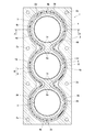
以下に本発明の実施の形態について、図1〜図11を参照して説明する。図1〜図3は、第一の発明に係るスペーサの一実施形態を示し、図1は、同実施形態のスペーサを内燃機関におけるシリンダブロックのウォータジャケットに配置した状態を示している。図1に示すシリンダブロック2は、3気筒の自動車用エンジン(内燃機関)1を構成するものであり、3個のシリンダボア(気筒)3…が隣接状態で直列に連なるように設けられている。2a…は、シリンダヘッド5(図2及び図3(b)参照)をシリンダブロック2に合体締結させるためのボルト(不図示)用挿通孔である。3個のシリンダボア3…の周囲には、オープンデッキタイプの溝形状のウォータジャケット(冷却水流路)4が一連に形成されている。シリンダブロック2には、このウォータジャケット4に通じる冷却水(不凍液も含む)導入口2bと冷却水排出口2cとが設けられている。冷却水排出口2cは、不図示のラジエータに配管接続され、ラジエータのアウトレット側は、ウォータポンプ(不図示)を介して冷却水導入口2bに配管接続される。これによって、ウォータジャケット4とラジエータとの間で冷却水が循環するように構成される。なお、シリンダヘッド5にもウォータジャケット(不図示)が設けられる場合は、シリンダブロック2のウォータジャケット4と、シリンダヘッド5のウォータジャケットとが連通するよう構成される。この場合は、シリンダブロック2には、前記冷却水排出口2cがなくても良く、シリンダヘッド5に冷却水排出口が設けられ、これにラジエータに通じる配管が接続される。
Embodiments of the present invention will be described below with reference to FIGS. 1 to 3 show an embodiment of a spacer according to the first invention, and FIG. 1 shows a state in which the spacer of the embodiment is arranged in a water jacket of a cylinder block in an internal combustion engine. A
ウォータジャケット4における隣接するシリンダボア3,3間の部分には、互いに接近して対をなすくびれ部4a…が形成されている。くびれ部4a…の溝幅は、ウォータジャケット4の他の円弧部4bの溝幅より大とされている。そして、ウォータジャケット4の両内壁面は、シリンダボア3側の内壁面4cと、シリンダボア3とは反対側の内壁面4dとにより構成される。本実施形態のスペーサ6は、図1に示すように、ウォータジャケット4内に、その開口部40から挿入されて配置可能な筒状の形状とされたスペーサ本体7と、スペーサ本体7におけるウォータジャケット4の深さ方向aの下端部7a(図2、図3参照)に固着によって一体に設けられた発泡体8とを備えている。スペーサ本体7は、シリンダボア3の外形状に沿うよう形成された円弧部70と、ウォータジャケット4のくびれ部4aに対応する位置であるとともに円弧部70に連続するくびれ形状部71とを有している。スペーサ本体7は、剛性を有し、図例では、硬質合成樹脂の成型体からなる。また、本実施形態の発泡体8は、冷却水と接触することによって圧縮された状態から復元可能なセルロース系スポンジによって構成されている。セルロース系スポンジとは、パルプ由来のセルロースと、補強繊維として加えられた天然繊維(例えば、綿等)とからなる天然素材である。なお、セルロースは、親水基(OH)を有しており、化学的に水分になじみ易い性質を有する。また、セルロース系スポンジは、多孔質の素材である。セルロース系スポンジは、加圧した状態で乾燥させるとセルロース分子間が水素結合して圧縮状態に維持される一方、この状態から冷却水に晒されると水分子がセルロース分子間の水素結合を解離して圧縮状態から復元する特性を有する。
In the
本実施形態のスペーサ6は、スペーサ本体7の下端部7aに一体に固着された平面視円弧形状の発泡体8を備えている。発泡体8は、スペーサ本体7とウォータジャケット4の深さ方向aにおいて重なる位置に設けられている。発泡体8は、ウォータジャケット4の溝幅方向における幅寸法が、スペーサ本体7の厚みとほぼ同じになるように設けられている。なお、発泡体8はスペーサ本体7のくびれ形状部71の下端部にも一体とされていても良い。このようなスペーサ6は、以下の要領で製造される。即ち、市場で入手可能な発泡状態のセルロース系スポンジのマット状原材を厚み方向に圧縮して乾燥し、シート状体となす。具体例としては、セルロース系スポンジの原材をプレスローラにて加圧及び加熱することで、シート状となす。そして、セルロース系スポンジのシート状体を所定形状に裁断する一方、スペーサ本体7は、射出成型によって別個に作製する。その後、接着剤によって発泡体8の上面8bをスペーサ本体7の所定位置(本実施形態ではスペーサ本体7の下端部7a)に固着させるか、スペーサ本体7の対応箇所を熱溶融させ、この部位に発泡体8を熱溶着によって固着させるようにしても良い。或いは、スペーサ本体7と圧縮されたシート状のセルロース系スポンジとをインサート成型によって一体に作製することも可能である。なお、スペーサ本体7とセルロース系スポンジとがインサート成型によって一体に作製された場合は、スペーサ本体7の樹脂の一部がセルロース系スポンジに含浸することで、発泡体8はスペーサ本体7に固着している。このスペーサ本体7に対する発泡体8の固着は、発泡体8の圧縮方向がウォータジャケット4の深さ方向aに沿うようになされる。
The
このようにして得られたスペーサ6は、ウォータジャケット4に配置可能な形状に形成された剛性を有するスペーサ本体7と、圧縮された状態でスペーサ本体7と一体に設けられて、ウォータジャケット4内で所定の外的要因が付加されたことを契機としてウォータジャケット4の深さ方向aに膨張可能な発泡体8とを備える。この場合、発泡体8を構成するセルロース系スポンジは、未だ圧縮前の状態に復元していない状態で、スペーサ本体7の下端部7aに固着されている。発泡体8が圧縮された状態におけるスペーサ6は、そのウォータジャケット4の深さ方向aに沿った最大高さが、ウォータジャケット4の深さより小さい。そして、スペーサ6は、ウォータジャケット4の開口部40から挿入されてウォータジャケット4内に配置される。後記する冷却水wがウォータジャケット4に冷却水導入口2bから導入されてウォータジャケット4内を流通すると、発泡体8のセルロース系スポンジが冷却水wに晒され、水分子がセルロース分子間の水素結合を解離して発泡体8は圧縮状態から復元する。発泡体8が復元することによって、発泡体8の下面8a(スペーサ6の深さ方向aにおける他方の端部)が、ウォータジャケット4内の底部4eに達して当接する。図2における発泡体8は、セルロース系スポンジが復元した状態を示す。発泡体8の復元によりスペーサ本体7は押し上げられ、スペーサ本体7の上端部7b(スペーサ6の深さ方向aにおける一方の端部)がウォータジャケット4の開口部40に達し、後記するようにシリンダヘッドガスケット9の下面9aに当接する。シリンダヘッドガスケット9がシリンダブロック2とシリンダヘッド5との間に保持されることによって、ウォータジャケット4の開口部40からの冷却水の漏出が防止される。
The
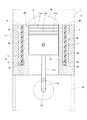
図2は、スペーサ6がシリンダブロック2のウォータジャケット4内に配置された状態を示している。図2は、シリンダブロック2の上面にシリンダヘッド5が一体に締結され、シリンダブロック2の下面にオイルパン10が一体に締結された状態を示している。さらに、図2は、シリンダボア3とオイルパン10間にピストン11が組み込まれた状態を示している。シリンダヘッド5は、シリンダヘッドガスケット9を介してウォータジャケット4の開口部40が塞がれるようにシリンダブロック2に一体に締結される。この締結状態では、シリンダボア3の上側開口部上に燃焼室5aが位置付けられる。シリンダボア3内には、複数(図例では、3個)のピストンリング11a,11b,11cを有するピストン11が、シリンダボア壁2dの内面を摺接してその軸方向に沿って往復動可能に設けられる。このピストン11の往復動は、コンロッド11d及びクランクピン11eを介してクランクシャフト11fの軸回転運動(1点鎖線)に変換される。図2は、ピストン11が上死点にある状態を示している。シリンダヘッドガスケット9がシリンダブロック2とシリンダヘッド5との間に保持されることによって、ウォータジャケット4の開口部40からの冷却水の漏出が防止される。
FIG. 2 shows a state in which the
前記のように構成されるエンジン(内燃機関)が作動すると、燃焼室5aによる熱によってシリンダボア壁2dが加熱される。シリンダボア壁2dの温度が高くなり過ぎると、ピストンリング11a,b,cに付着するオイルの粘性が下がり、これによってオイルが流出して、ピストン11の前記シリンダボア2内での前記往復摺接運動が円滑になされなくなる。然るに、ウォータジャケット4内には、前記冷却水が流通しているから、シリンダボア壁2dの過熱が抑制され、前記オイルの流出を抑えて、ピストン11の円滑な往復動が維持される。そして、ウォータジャケット4内には、発泡体8を備えたスペーサ6が配置されているから、ウォータジャケット4内を流通する冷却水の流れ(流量、流速等)を規制し、シリンダボア壁2dの温度が適正にコントロールされる。
When the engine (internal combustion engine) configured as described above operates, the
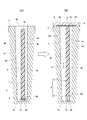
図3(a)(b)は、本実施形態のスペーサ6をウォータジャケット4に組付ける過程を模式的に示している。図3(a)は、前記のように作製されたスペーサ6を、ウォータジャケット4内にその開口部40から挿入して配置した状態を示している。この配置状態では、ウォータジャケット4内で深さ方向aの上端或いは下端に隙間が存在する。したがって、シリンダブロック2にシリンダヘッド5を組付ける過程では、シリンダヘッド5にスペーサ6の荷重がかからず、そのため、シリンダヘッド5をシリンダブロック2にボルト締めする際の締付けトルクに影響を与えることがない。これによって、シリンダブロック2に対するシリンダヘッド5の組付け性が低下する懸念が少なくなる。
FIGS. 3A and 3B schematically show a process of assembling the
そして、図3(b)に示すように、シリンダブロック2にシリンダヘッド5が締結一体とされ、ウォータジャケット4に冷却水w(外的要因)が流通すると、前記のとおり発泡体8を構成するセルロース系スポンジが圧縮状態から復元して前記深さ方向aに膨張する。換言すると、スペーサ6の深さ方向aに沿った高さが拡大する。発泡体8の下面8a(スペーサ6の深さ方向aにおける他方の端部)がウォータジャケット4の底部4eに達して当接する。一方、スペーサ本体7の上端部7b(スペーサ6の深さ方向aにおける一方の端部)がウォータジャケット4の開口部40に達し、シリンダヘッドガスケット9の下面(ウォータジャケット4に向く面)9aに当接する。このような状態では、エンジン1の振動や水流によっても、スペーサ6の変位が抑制されウォータジャケット4内の所定位置にスペーサ6が安定的に固定される。また、発泡体8が膨張すると、ウォータジャケット4の深さ方向aに存在していた隙間を減少させることができ、隙間を通過してシリンダボア3側に回り込む冷却水の流通量を減少させることができるため、シリンダボア壁2dに対する過冷却を抑制することができる。さらに、水流や振動によるウォータジャケット4の深さ方向aにおけるスペーサ6の変位が抑制されるため、スペーサ6とウォータジャケット4の内壁面4c、4dとの摩擦によるスペーサ6の摩耗を抑制でき、ウォータジャケット4内における異物の発生量を減らすことができる。加えて、スペーサ6の変位による、スペーサ6とシリンダヘッドガスケット9のようなシリンダブロック2の構成部分との干渉を抑制することができる。
Then, as shown in FIG. 3B, when the
また、本実施形態では、発泡体8は、スペーサ本体の円弧部70に沿うような形状に形成されている。ウォータジャケット4におけるシリンダボア3の外形状に沿う円弧状部分のシリンダボア壁2dは、シリンダボア壁2dとは反対側を流れる冷却水がシリンダボア壁2d側に回り込むことで過冷却され易い。しかし、本実施形態では発泡体8がスペーサ本体7の円弧部70に沿うような形状に形成されているから、円弧部70の上側及び下側の隙間を通過して円弧部70におけるシリンダボア壁側へ回り込む冷却水の量を減少させることができる。その結果、スペーサ6により、当該シリンダボア壁2dを適正に冷却することができる。
なお、以下の実施形態においても、発泡体8がスペーサ本体7の円弧部70に沿うような形状に形成されているものとする。
Moreover, in this embodiment, the
In the following embodiments, it is also assumed that the
さらに、本実施形態では、発泡体としてセルロース系スポンジを用いているから、化学薬品等を使用せずに発泡体8を圧縮状態に保つことができ、発泡体8の加工工程を簡素化することができる。また、冷却水wや環境に対する悪影響も生じる懸念がなく、しかも、セルロース系スポンジは、天然素材からなるから、安価に入手することができる上に、自然環境に悪影響を及ぼすこともなく、廃棄処理等も焼却等によって容易に行うことができる。さらに、スペーサ本体7と発泡体8とは面同士で結合されており、スペーサ本体7に対する発泡体8の位置を安定させることができる。因みに、発泡体8としてバインダーを用いて発泡ゴムを圧縮状態に固定する場合は、発泡ゴムの表面がバインダーで被覆されることになり、バインダーがスペーサ本体と発泡ゴムとの界面に存在する。このようなスペーサが冷却水に晒されると、スペーサ本体と発泡ゴムとの界面に介在するバインダーも冷却水に晒されて冷却水に溶け出し、スペーサ本体と発泡ゴムとの接着強度が低下する懸念がある。これに対して、セルロース系スポンジを用いる場合は、このような懸念が生じない。
Furthermore, in this embodiment, since the cellulosic sponge is used as the foam, the
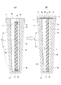
図4(a)(b)〜図9(a)(b)は、第一の発明に係るスペーサの他の実施形態を示す。以下、順次説明する。
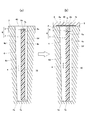
図4(a)(b)に示すスペーサ6においては、スペーサ本体7の上端部7bに発泡体8の下面8aが固着されている。この場合のスペーサ6も、図4(a)に示すように、ウォータジャケット4内に配置される。この配置状態で図4(b)に示すように、シリンダブロック2にシリンダヘッド5が締結一体とされる。ここで、シリンダブロック2にシリンダヘッド5を組付ける過程では、シリンダヘッド5にスペーサ6の荷重がかからず、そのため、シリンダヘッド5をシリンダブロック2にボルト締めする際の締付けトルクに影響を与えることがない。これによって、シリンダブロック2に対するシリンダヘッド5の組付け性が低下する懸念が少なくなる。そして、ウォータジャケット4に冷却水w(外的要因)が流通すると、前記のとおり発泡体8を構成するセルロース系スポンジが圧縮状態から復元して前記深さ方向aに膨張し、発泡体8の上面8b(スペーサ6の深さ方向aにおける一方の端部)がウォータジャケット4の開口部40に達し、シリンダヘッドガスケット9の下面9aに当接する。また、スペーサ本体7の下端部7a(スペーサ6の深さ方向aにおける他方の端部)がウォータジャケット4の底部4eに達して当接する。
4 (a), 4 (b) to 9 (a), 9 (b) show other embodiments of the spacer according to the first invention. Hereinafter, the description will be made sequentially.
In the
また、本実施形態の場合、発泡体8は、冷却水の流れを規制する機能を有するが、完全に冷却水の通過を遮断するものではない。そして発泡体8が復元すると、スペーサ本体7の下端部7aがウォータジャケット4の底部4eに当接することになるから、発泡体8をスペーサ本体7の下端部7aに設ける場合に比べて、スペーサ本体7の下端部7a側からの冷却水の回り込みを抑制し、シリンダボア壁2dの下側部分の過冷却を防止する効果が大きくなる。さらに、シリンダブロック2とシリンダヘッド5との間に介在されるシリンダヘッドガスケット9に発泡体8が干渉しても、発泡体8はスペーサ本体7より剛性が少ないから、シリンダヘッドガスケット9を傷つける恐れが少ない。
本実施形態のスペーサ6のその他の作用・効果も前記実施形態と同様に奏し、また、その他の構成も前記実施形態と同様であるから、共通部分に同一の符号を付し、これらの説明は割愛する。
In the present embodiment, the
The other actions and effects of the
図5(a)(b)に示すスペーサ6においては、スペーサ本体7の下端部7a及び上端部7bに、それぞれ発泡体8,8が固着されている。スペーサ本体7の下端部7aには、下側に位置する発泡体8の上面8bが固着される一方、スペーサ本体7の上端部7bには、上側に位置する発泡体8の下面8aが固着されている。この場合のスペーサ6も、図5(a)に示すように、ウォータジャケット4内に配置される。この配置状態で図5(b)に示すように、シリンダブロック2にシリンダヘッド5が締結一体とされる。ここで、シリンダブロック2にシリンダヘッド5を組付ける過程では、シリンダヘッド5にスペーサ6の荷重がかからず、そのため、シリンダヘッド5をシリンダブロック2にボルト締めする際の締付けトルクに影響を与えることがない。これによって、シリンダブロック2に対するシリンダヘッド5の組付け性が低下する懸念が少なくなる。そして、ウォータジャケット4に冷却水w(外的要因)が流通すると、前記のとおり上下の両発泡体8,8を構成するセルロース系スポンジが圧縮状態から復元して前記深さ方向aに膨張し、上側の発泡体8の上面8b(スペーサ6の深さ方向aにおける一方の端部)は、ウォータジャケット4の開口部40に達し、シリンダヘッドガスケット9の下面9aに当接する。また、下側の発泡体8の下面8a(スペーサ6の深さ方向aにおける他方の端部)がウォータジャケット4の底部4eに達して当接する。
In the
本実施形態のスペーサ6は、実質的に、前記第一の実施形態及び第二の実施形態のスペーサ6を複合したものであり、したがって、前記両実施形態のスペーサ6のそれぞれの作用・効果を併せ持つことになる。また、その他の構成も前記実施形態と同様であるから、共通部分に同一の符号を付し、これらの説明は割愛する。
The
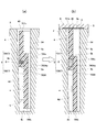
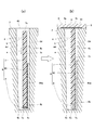
図6(a)(b)及び図7(a)(b)に示すスペーサ6は、スペーサ本体7が前記深さ方向aに分割されてなる下側分割体700及び上側分割体701を備える。下側分割体700はスペーサ本体7における下側に位置する一方、上側分割体701はスペーサ本体7における上側に位置する。また、スペーサ6は、両分割体700,701間に介在する発泡体8を備える。
図6(a)(b)に示すスペーサ6においては、スペーサ本体7における下側分割体700の上部にウォータジャケット4の外側内壁面4d側に向く突出部700Aが設けられ、この突出700Aの上面700Aaに発泡体8の下面8aが固着されている。また、上側分割体701の下端部701aには、発泡体8の上面8bが固着されている。下側分割体700と上側分割体701とは、それぞれの一部がウォータジャケット4の溝幅方向bに重なり、この重なり部分では、互いに摺接可能に構成されている。この場合のスペーサ6も、図6(a)に示すように、ウォータジャケット4内に配置される。この配置状態で、図6(b)に示すように、シリンダブロック2にシリンダヘッド5が締結一体とされる。ここで、シリンダブロック2にシリンダヘッド5を組付ける過程では、シリンダヘッド5にスペーサ6の荷重がかからず、そのため、シリンダヘッド5をシリンダブロック2にボルト締めする際の締付けトルクに影響を与えることがない。これによって、シリンダブロック2に対するシリンダヘッド5の組付け性が低下する懸念が少なくなる。そして、ウォータジャケット4に冷却水w(外的要因)が流通すると、前記のとおり発泡体8を構成するセルロース系スポンジが圧縮状態から復元して前記深さ方向aに膨張する。これに伴い、スペーサ本体7における上側分割体701は上向きに変位し、その上端部701b(スペーサ6の深さ方向aにおける一方の端部)が、ウォータジャケット4の開口部40に達し、シリンダヘッドガスケット9の下面9aに当接する。また、スペーサ本体7における下側分割体700が下向きに変位し、その下端部700a(スペーサ6の深さ方向aにおける他方の端部)がウォータジャケット4の底部4eに達して当接する。
なお、本実施形態において、発泡体8は、スペーサ本体7における分割体700,701の両方に固着されているが、これに限らず少なくともいずれか一方に固着されていても良い。その他の作用・効果及びその他の構成は前記例と同様であるから、これらの説明は割愛する。
In the
In the present embodiment, the
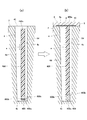
図7(a)(b)に示すスペーサ6においては、スペーサ本体7における下側分割体700の上部に上向きに開口する凹溝部700Bが設けられ、この凹溝部700Bの底面700Baに発泡体8の下面8aが固着されている。また、上側分割体701の下端部701aには、発泡体8の上面8bが固着されている。この場合のスペーサ6も、図7(a)に示すように、ウォータジャケット4内に配置される。この配置状態で図7(b)に示すように、シリンダブロック2にシリンダヘッド5が締結一体とされ、ウォータジャケット4に冷却水w(外的要因)が流通すると、前記のとおり発泡体8を構成するセルロース系スポンジが圧縮状態から復元して前記深さ方向aに膨張する。これに伴い、スペーサ本体7における上側分割体701は上向きに変位し、その上端部701b(スペーサ6の深さ方向aにおける一方の端部)が、ウォータジャケット4の開口部40に達し、シリンダヘッドガスケット9の下面9aに当接する。また、スペーサ本体7における下側分割体700が下向きに変位し、その下端部700a(スペーサ6の深さ方向aにおける他方の端部)がウォータジャケット4の底部4eに達して当接する。したがって、図6に示す例と同様の作用・効果を奏する。
その他の構成は、図6に示す例と同様であるから、共通部分に同一の符号を付し、その説明は割愛する。
In the
Since the other configuration is the same as the example shown in FIG. 6, the same reference numerals are given to the common parts, and the description thereof is omitted.
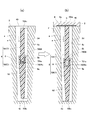
図8(a)(b)及び図9(a)(b)に示すスペーサ6は、図2及び図3に示す第一の実施形態に加えて、スペーサ本体7におけるシリンダボア壁2d側に向く内側面7cに固着された別の発泡体80をさらに有している。図8(a)(b)に示すスペーサ6においては、発泡体80がスペーサ本体7の下端部7aに固着された発泡体8と前記溝幅方向bにおいて重ならない位置で、その圧縮方向がウォータジャケット4の前記溝幅方向bに向くようにスペーサ本体7の内側面7cに固着されている。一方、図9(a)(b)に示すスペーサ6においては、発泡体80が発泡体8と前記溝幅方向bに一部が重なる位置で、前記と同様にその圧縮方向が前記溝幅方向bに向くようにスペーサ本体7の内側面7cに固着されている。発泡体8と発泡体80との重なり部分は互いに固着されていない。
The
これらの場合のスペーサ6も、図8(a)及び図9(a)に示すように、ウォータジャケット4内に配置される。この配置状態で、図8(b)及び図9(b)に示すように、シリンダブロック2にシリンダヘッド5が締結一体とされ、ウォータジャケット4に冷却水w(外的要因)が流通すると、前記のとおり発泡体8を構成するセルロース系スポンジが圧縮状態から復元して前記深さ方向aに膨張する。これに伴い、スペーサ本体7の上端部7b(スペーサ6の深さ方向aにおける一方の端部)が、ウォータジャケット4の開口部40に達し、シリンダヘッドガスケット9の下面9aに当接する。また、下側の発泡体8a(スペーサ6の深さ方向における他方の端部)は、ウォータジャケット4の底部4eに達して当接する。さらに、発泡体80が前記溝幅方向bに沿って膨張し、発泡体80のシリンダボア壁2d側に向く面80aが、ウォータジャケット4の内側内壁面4cに当接する。
The
図8及び図9に示す実施形態では、スペーサ本体7の下端部7aに固着された発泡体8によって、図2及び図3に示す例と同様の作用・効果を奏する。加えて、発泡体80がウォータジャケット4の内側内壁面4cに当接することにより、ウォータジャケット4内でのスペーサ6の位置はより安定化される。また、スペーサ本体7の内側面7cとウォータジャケット4の内側内壁面4cとの間に発泡体80が介在することにより、この部分を流通する冷却水wの流れが規制されて、シリンダボア壁2dの冷却が適正になされる。
その他の作用・効果及びその他の構成は前記例と同様であるから、これらの説明は割愛する。
In the embodiment shown in FIGS. 8 and 9, the
Since other operations / effects and other configurations are the same as those in the above example, a description thereof will be omitted.
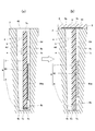
図10(a)(b)及び図11(a)(b)は、第二の発明に係るシリンダブロックの冷却構造の実施形態を示す。これらの実施形態のシリンダブロックの冷却構造は、ウォータジャケット4内に冷却水wの流れを規制するスペーサ600が配置され、圧縮された状態でウォータジャケット4の深さ方向aにおいてスペーサ600と重なる位置に設けられ、ウォータジャケット4内で所定の外的要因が付加されたことを契機として、ウォータジャケット4の深さ方向aに膨張可能な発泡体800を備えていることを特徴とする。発泡体800は、その圧縮方向がウォータジャケット4の深さ方向aに沿うように位置付けられる。
FIGS. 10A, 10B and 11A, 11B show an embodiment of a cooling structure for a cylinder block according to the second invention. In the cooling structure of the cylinder block of these embodiments, the
図10(a)(b)に示すシリンダブロックの冷却構造においては、シリンダヘッドガスケット9の下面9aに前記と同様のセルロース系スポンジからなる発泡体800が固着されている。そして、ウォータジャケット4内には、ウォータジャケット4の形状に沿った筒状の樹脂成型体からなるスペーサ600が、開口部40から挿入されて配置される。この配置状態で、図10(b)に示すように、シリンダブロック2にシリンダヘッド5が締結一体とされ、ウォータジャケット4に冷却水w(外的要因)が流通すると、前記のとおり発泡体800を構成するセルロース系スポンジが圧縮状態から復元して前記深さ方向aに膨張する。これに伴い、発泡体800の下面800aがスペーサ600の上端部600aに当接し、発泡体800がさらに膨張することによりスペーサ600が前記深さ方向aに沿って押し下げられ、スペーサ600の下端部600bがウォータジャケット4の底部4eに達して当接する。その結果、スペーサ600がウォータジャケット4の深さ方向aにおいて変位することが抑制される。これによって、スペーサ600はウォータジャケット4内の冷却水wの流れを制御する機能を安定して発揮でき、シリンダブロック2は適正に冷却されるようになる。
In the cooling structure of the cylinder block shown in FIGS. 10 (a) and 10 (b), a
図11(a)(b)に示すシリンダブロックの冷却構造においては、発泡体800は、シリンダヘッドガスケット9にもスペーサ600にも一体とされず、スペーサ600とは個別にウォータジャケット4内に配置される。図11(a)では、発泡体800がウォータジャケット4の底部4e側に、スペーサ600が前記深さ方向aの上側に位置するように配置された例を示しているが、この逆の配置関係でも良い。つまり、発泡体800がウォータジャケット4の深さ方向aの上側に、スペーサ600がウォータジャケット4の底部4e側に配置されていても良い。図11(a)に示す配置状態で、図11(b)に示すように、シリンダブロック2にシリンダヘッド5が締結一体とされ、ウォータジャケット4に冷却水w(外的要因)が流通すると、前記のとおり発泡体800を構成するセルロース系スポンジが圧縮状態から復元して前記深さ方向aに膨張する。これに伴い、発泡体800の下面800aがウォータジャケット4の底部4eに当接すると共に、発泡体800の上面800bがスペーサ600の下端部600bに当接する。発泡体800がさらに膨張することによりスペーサ600が前記深さ方向aに沿って押し上げられ、スペーサ600の上端部600aがシリンダヘッドガスケット9の下面9aに達して当接する。その結果、スペーサ600がウォータジャケット4の深さ方向aにおいて変位することが抑制される。これによって、スペーサ600はウォータジャケット4内の冷却水wの流れを制御する機能を安定して発揮でき、シリンダブロック2は適正に冷却されるようになる。
なお、第二の発明に係るシリンダブロックの冷却構造では、発泡体800がウォータジャケット4の深さ方向aにおいてスペーサ600と重なる位置に設けられておれば、その他の態様については特に限定されない。例えば、発泡体800はウォータジャケット4の底部4eに一体に設けられていても良いし、スペーサ600に一体に設けられていても良い。
In the cooling structure of the cylinder block shown in FIGS. 11 (a) and 11 (b), the
In the cylinder block cooling structure according to the second aspect of the present invention, other aspects are not particularly limited as long as the
なお、前記実施形態では、ウォータジャケット4の溝幅方向における幅寸法がスペーサ本体7の厚みとほぼ同じ発泡体8,800の例について述べたが、これに限らない。例えば、発泡体8,800の幅寸法は、スペーサ本体7の厚みより大きくてもよいし、スペーサ本体7の厚みより小さくても良い。発泡体8,80,800の平面視形状は、円弧形状に限らない。例えば、発泡体8,80,800をスペーサ本体7の平面視形状と同様な平面視筒形状に変更しても良い。発泡体8,80,800としてセルロース系スポンジを用いた例について述べたが、これに限らず、水に可溶性或いは熱に溶融性(外的要因)のバインダーで圧縮状態に固定されたゴム発泡体を用いることも可能である。また、セルロース系スポンジとして、種々の種類のものが挙げられるが、特に限定されない。例えば、気泡の大きさが非常に小さい微粒品、気泡の大きさが小程度の小粒品、気泡の大きさが中程度の中粒品のいずれを用いても良い。具体的には、気泡の大きさ(径)が0.1〜5mm程度のセルロース系スポンジを用いても良い。これらの気泡の大きさはセルロース系スポンジの作製過程で使用される結晶ぼう硝の粒度によって決定される。また、セルロース系スポンジは、セルロースと補強繊維とからなるものに限らず、セルロース単独で構成されるものであっても良い。また、セルロース系スポンジとは、セルロース自体からなるスポンジの他、圧縮状態を保持できる程度にセルロースの水酸基を残したセルロース誘導体、例えば、セルロースエ−テル類、セルロースエステル類等からなるスポンジ、或いは、これらの混合物からなるスポンジのいずれかから選ばれるものであっても良い。
In the above-described embodiment, the example of the
また、スペーサ6或いはスペーサ600が合成樹脂の成型体からなる例について述べたが、金属など、セルロース系スポンジより剛性を有するものであれば、他の材料からなるものであっても良い。また、スペーサ6,600をウォータジャケット4の全体形状に整合する筒形状としたが、例えば、シリンダボア3の外形状に沿うように形成され、ウォータジャケット4内の適所に部分的に配置されるいわゆる部分スペーサであっても良い。さらにまた、本発明のスペーサが適用される内燃機関として、3気筒のエンジンを例示したが、これに限らず他の気筒数のエンジンにも適用可能である。また、本発明のスペーサは、クローズドデッキタイプのウォータジャケットを備えたエンジンにも適用可能である。また、本発明のスペーサは、直列エンジンに限らず、V型エンジン、水平対向エンジンにも適用可能である。前記実施形態における上側及び下側とは、重力作用する方向を基準としたのではなく、ウォータジャケット4の深さ方向aを基準としたものである。前記実施形態における上側及び下側とは、水平対向エンジンに適用される場合、ウォータジャケット4の開口部40側及び底部4e側と読み替えても良い。加えて、発泡体の膨張によって、スペーサ、スペーサ本体が直接或は発泡体を介して、ウォータジャケットの底部及びシリンダヘッドガスケットの下面に当接する例について述べたが、どちらか一方が近接する状態、或いは両方共が近接する状態となることも除外されるものではない。
In addition, the example in which the
1 エンジン(内燃機関)
2 シリンダブロック
3 シリンダボア
4 ウォータジャケット(冷却水流路)
4e 底部
40 開口部
5 シリンダヘッド
6,600 スペーサ
7 スペーサ本体
7a 下端部
7b 上端部
70 円弧部
8,80,800 発泡体
9 シリンダヘッドガスケット
9a 下面(冷却水流路に向く面)
a ウォータジャケット(冷却水流路)の深さ方向
w 冷却水(外的要因)
1 engine (internal combustion engine)
2
a Water jacket (cooling water flow path) depth direction w Cooling water (external factor)
Claims (8)
前記冷却水流路に配置可能な形状に形成された剛性を有するスペーサ本体と、
圧縮された状態で前記スペーサ本体と一体に設けられて、前記冷却水流路内で所定の外的要因が付加されたことを契機として前記冷却水流路の深さ方向に膨張可能な発泡体と、を備えていることを特徴とするスペーサ。 A spacer that is disposed in a cooling water flow path provided in a cylinder block of an internal combustion engine and regulates the flow of cooling water,
A rigid spacer body formed in a shape that can be disposed in the cooling water flow path;
A foam that is provided integrally with the spacer main body in a compressed state, and is expandable in the depth direction of the cooling water flow channel when a predetermined external factor is added in the cooling water flow channel, A spacer characterized by comprising:
前記発泡体は、当該スペーサの前記冷却水流路の深さ方向における一方の端部が前記冷却水流路の開口部に達し、当該スペーサの前記深さ方向における他方の端部が前記冷却水流路の底部に達するまで前記膨張がなされるように構成されていることを特徴とするスペーサ。 The spacer according to claim 1,
In the foam, one end of the spacer in the depth direction of the cooling water channel reaches the opening of the cooling water channel, and the other end of the spacer in the depth direction of the cooling water channel. A spacer configured to be expanded until reaching the bottom.
前記発泡体は、前記冷却水流路の深さ方向における前記スペーサ本体の下端部に設けられていることを特徴とするスペーサ。 The spacer according to claim 1 or 2,
The said foam is provided in the lower end part of the said spacer main body in the depth direction of the said cooling water flow path, The spacer characterized by the above-mentioned.
前記発泡体は、前記冷却水流路の深さ方向における前記スペーサ本体の上端部に設けられていることを特徴とするスペーサ。 In the spacer according to any one of claims 1 to 3,
The said foam is provided in the upper end part of the said spacer main body in the depth direction of the said cooling water flow path, The spacer characterized by the above-mentioned.
前記スペーサ本体は、前記シリンダブロックに設けられるシリンダボアの外形状に沿うよう形成された円弧部を備え、
前記発泡体は、前記円弧部に沿うような形状に形成されていることを特徴とするスペーサ。 In the spacer according to any one of claims 1 to 4,
The spacer body includes an arc portion formed along the outer shape of a cylinder bore provided in the cylinder block,
The said foam is formed in the shape which follows the said circular arc part, The spacer characterized by the above-mentioned.
前記発泡体は、水分に接したことを契機として、圧縮された状態から復元可能なセルロース系スポンジからなることを特徴とするスペーサ。 In the spacer according to any one of claims 1 to 5,
The said foaming body consists of a cellulosic sponge which can be restored | restored from the compressed state by having contacted the water | moisture content.
圧縮された状態で前記冷却水流路の深さ方向において前記スペーサと重なる位置に設けられ、前記冷却水流路内で所定の外的要因が付加されたことを契機として、前記冷却水流路の深さ方向に膨張可能な発泡体を備えていることを特徴とするシリンダブロックの冷却構造。 In the cooling structure of the cylinder block in which the spacer for restricting the flow of the cooling water is arranged in the cooling water flow path provided in the cylinder block of the internal combustion engine,
The depth of the cooling water flow path is provided at a position overlapping with the spacer in the depth direction of the cooling water flow path in a compressed state, and when a predetermined external factor is added in the cooling water flow path A cooling structure for a cylinder block comprising a foam that is expandable in a direction.
前記シリンダブロックとシリンダヘッドとで保持されて前記冷却水流路を塞ぐシリンダヘッドガスケットを備え、
前記発泡体は、前記シリンダヘッドガスケットの前記冷却水流路に向く面に設けられていることを特徴とするシリンダブロックの冷却構造。 In the cooling structure of the cylinder block according to claim 7,
A cylinder head gasket that is held by the cylinder block and the cylinder head and closes the cooling water flow path;
The cooling structure of a cylinder block, wherein the foam is provided on a surface of the cylinder head gasket facing the cooling water flow path.
Priority Applications (1)
| Application Number | Priority Date | Filing Date | Title |
|---|---|---|---|
| JP2016050739A JP6711513B2 (en) | 2016-03-15 | 2016-03-15 | Cylinder block cooling structure |
Applications Claiming Priority (1)
| Application Number | Priority Date | Filing Date | Title |
|---|---|---|---|
| JP2016050739A JP6711513B2 (en) | 2016-03-15 | 2016-03-15 | Cylinder block cooling structure |
Publications (2)
| Publication Number | Publication Date |
|---|---|
| JP2017166364A true JP2017166364A (en) | 2017-09-21 |
| JP6711513B2 JP6711513B2 (en) | 2020-06-17 |
Family
ID=59909871
Family Applications (1)
| Application Number | Title | Priority Date | Filing Date |
|---|---|---|---|
| JP2016050739A Active JP6711513B2 (en) | 2016-03-15 | 2016-03-15 | Cylinder block cooling structure |
Country Status (1)
| Country | Link |
|---|---|
| JP (1) | JP6711513B2 (en) |
Cited By (3)
| Publication number | Priority date | Publication date | Assignee | Title |
|---|---|---|---|---|
| CN111287858A (en) * | 2018-12-06 | 2020-06-16 | 现代自动车株式会社 | Structure installed in water jacket for cylinder block |
| JP2021080858A (en) * | 2019-11-18 | 2021-05-27 | マツダ株式会社 | Water jacket spacer |
| EP4579073A1 (en) * | 2023-12-27 | 2025-07-02 | Mazda Motor Corporation | Water jacket spacer and engine |
Citations (9)
| Publication number | Priority date | Publication date | Assignee | Title |
|---|---|---|---|---|
| JPH02168924A (en) * | 1988-12-23 | 1990-06-29 | Lion Corp | cleaning tools |
| JPH0461523U (en) * | 1990-10-03 | 1992-05-27 | ||
| JP2005030297A (en) * | 2003-07-11 | 2005-02-03 | Aisan Ind Co Ltd | Water jacket spacer and cylinder block provided with the spacer |
| JP2005256661A (en) * | 2004-03-10 | 2005-09-22 | Toyota Motor Corp | Cylinder block cooling structure |
| JP2007071039A (en) * | 2005-09-05 | 2007-03-22 | Uchiyama Mfg Corp | Water jacket spacer |
| JP2008031939A (en) * | 2006-07-31 | 2008-02-14 | Toyota Motor Corp | Heat medium passage partition member for cooling internal combustion engine, internal combustion engine cooling mechanism, and internal combustion engine cooling mechanism forming method |
| JP2011106391A (en) * | 2009-11-19 | 2011-06-02 | Honda Motor Co Ltd | Cooling structure for internal combustion engine |
| JP2015075065A (en) * | 2013-10-11 | 2015-04-20 | 内山工業株式会社 | Water jacket spacer manufacturing method |
| JP2015132217A (en) * | 2014-01-14 | 2015-07-23 | 内山工業株式会社 | Water jacket spacer fixing structure |
-
2016
- 2016-03-15 JP JP2016050739A patent/JP6711513B2/en active Active
Patent Citations (9)
| Publication number | Priority date | Publication date | Assignee | Title |
|---|---|---|---|---|
| JPH02168924A (en) * | 1988-12-23 | 1990-06-29 | Lion Corp | cleaning tools |
| JPH0461523U (en) * | 1990-10-03 | 1992-05-27 | ||
| JP2005030297A (en) * | 2003-07-11 | 2005-02-03 | Aisan Ind Co Ltd | Water jacket spacer and cylinder block provided with the spacer |
| JP2005256661A (en) * | 2004-03-10 | 2005-09-22 | Toyota Motor Corp | Cylinder block cooling structure |
| JP2007071039A (en) * | 2005-09-05 | 2007-03-22 | Uchiyama Mfg Corp | Water jacket spacer |
| JP2008031939A (en) * | 2006-07-31 | 2008-02-14 | Toyota Motor Corp | Heat medium passage partition member for cooling internal combustion engine, internal combustion engine cooling mechanism, and internal combustion engine cooling mechanism forming method |
| JP2011106391A (en) * | 2009-11-19 | 2011-06-02 | Honda Motor Co Ltd | Cooling structure for internal combustion engine |
| JP2015075065A (en) * | 2013-10-11 | 2015-04-20 | 内山工業株式会社 | Water jacket spacer manufacturing method |
| JP2015132217A (en) * | 2014-01-14 | 2015-07-23 | 内山工業株式会社 | Water jacket spacer fixing structure |
Cited By (4)
| Publication number | Priority date | Publication date | Assignee | Title |
|---|---|---|---|---|
| CN111287858A (en) * | 2018-12-06 | 2020-06-16 | 现代自动车株式会社 | Structure installed in water jacket for cylinder block |
| CN111287858B (en) * | 2018-12-06 | 2023-05-30 | 现代自动车株式会社 | Structure mounted in water jacket for cylinder block |
| JP2021080858A (en) * | 2019-11-18 | 2021-05-27 | マツダ株式会社 | Water jacket spacer |
| EP4579073A1 (en) * | 2023-12-27 | 2025-07-02 | Mazda Motor Corporation | Water jacket spacer and engine |
Also Published As
| Publication number | Publication date |
|---|---|
| JP6711513B2 (en) | 2020-06-17 |
Similar Documents
| Publication | Publication Date | Title |
|---|---|---|
| JP6115928B2 (en) | Regulatory member | |
| JP6780836B2 (en) | Spacer | |
| KR950007627B1 (en) | Pistons for internal combustion engines and similar machinery | |
| JP2017166364A (en) | Spacer and cylinder block cooling structure | |
| JP2000504395A (en) | Hydraulic clamping device for traction mechanism | |
| JP2016128256A (en) | Composite molded product and manufacturing method thereof | |
| US9222434B2 (en) | Engine housing of an internal combustion engine and internal combustion engine fitted therewith | |
| JP2006317002A (en) | Slide bearing | |
| JP2009002478A (en) | Liquid sealed type vibration-control support device | |
| JP2004232653A (en) | Single cylinder type hydraulic shock absorber | |
| JP6842107B2 (en) | Internal combustion engine cooling structure | |
| JP6970956B2 (en) | Spacer | |
| JP6710391B2 (en) | Regulating member and cellulosic sponge | |
| JP6863576B2 (en) | Spacer | |
| KR20190112659A (en) | High-pressure fuel pump for a fuel injection system | |
| EP2841790B1 (en) | Assembly mount | |
| JP6974837B2 (en) | Spacer | |
| JP2016156277A (en) | Regulatory member | |
| JP3120892U (en) | Vibration isolator | |
| CN211819546U (en) | Oil stabilizer and engine having the same | |
| CN216866869U (en) | Diesel oil delivery system for diesel engine and diesel engine | |
| CN113931822B (en) | Cylinder block, pump body subassembly, compressor and refrigerator | |
| JP2007032711A (en) | Hydraulic auto-tensioner | |
| CN222316041U (en) | One-way valve | |
| JP6874975B2 (en) | Spacer |
Legal Events
| Date | Code | Title | Description |
|---|---|---|---|
| RD02 | Notification of acceptance of power of attorney |
Free format text: JAPANESE INTERMEDIATE CODE: A7422 Effective date: 20171011 |
|
| A621 | Written request for application examination |
Free format text: JAPANESE INTERMEDIATE CODE: A621 Effective date: 20190225 |
|
| A977 | Report on retrieval |
Free format text: JAPANESE INTERMEDIATE CODE: A971007 Effective date: 20191128 |
|
| A131 | Notification of reasons for refusal |
Free format text: JAPANESE INTERMEDIATE CODE: A131 Effective date: 20191210 |
|
| A521 | Request for written amendment filed |
Free format text: JAPANESE INTERMEDIATE CODE: A523 Effective date: 20200210 |
|
| TRDD | Decision of grant or rejection written | ||
| A01 | Written decision to grant a patent or to grant a registration (utility model) |
Free format text: JAPANESE INTERMEDIATE CODE: A01 Effective date: 20200421 |
|
| A61 | First payment of annual fees (during grant procedure) |
Free format text: JAPANESE INTERMEDIATE CODE: A61 Effective date: 20200521 |
|
| R150 | Certificate of patent or registration of utility model |
Ref document number: 6711513 Country of ref document: JP Free format text: JAPANESE INTERMEDIATE CODE: R150 |
|
| R250 | Receipt of annual fees |
Free format text: JAPANESE INTERMEDIATE CODE: R250 |
|
| R250 | Receipt of annual fees |
Free format text: JAPANESE INTERMEDIATE CODE: R250 |
|
| R250 | Receipt of annual fees |
Free format text: JAPANESE INTERMEDIATE CODE: R250 |