JP2017166329A - Diaphragm fuel pump for general-purpose engines - Google Patents
Diaphragm fuel pump for general-purpose engines Download PDFInfo
- Publication number
- JP2017166329A JP2017166329A JP2016049628A JP2016049628A JP2017166329A JP 2017166329 A JP2017166329 A JP 2017166329A JP 2016049628 A JP2016049628 A JP 2016049628A JP 2016049628 A JP2016049628 A JP 2016049628A JP 2017166329 A JP2017166329 A JP 2017166329A
- Authority
- JP
- Japan
- Prior art keywords
- rod
- diaphragm
- plunger
- pin
- fuel pump
- Prior art date
- Legal status (The legal status is an assumption and is not a legal conclusion. Google has not performed a legal analysis and makes no representation as to the accuracy of the status listed.)
- Granted
Links
Images


Classifications
-
- F—MECHANICAL ENGINEERING; LIGHTING; HEATING; WEAPONS; BLASTING
- F04—POSITIVE - DISPLACEMENT MACHINES FOR LIQUIDS; PUMPS FOR LIQUIDS OR ELASTIC FLUIDS
- F04B—POSITIVE-DISPLACEMENT MACHINES FOR LIQUIDS; PUMPS
- F04B43/00—Machines, pumps, or pumping installations having flexible working members
- F04B43/02—Machines, pumps, or pumping installations having flexible working members having plate-like flexible members, e.g. diaphragms
- F04B43/023—Machines, pumps, or pumping installations having flexible working members having plate-like flexible members, e.g. diaphragms double acting plate-like flexible member
-
- F—MECHANICAL ENGINEERING; LIGHTING; HEATING; WEAPONS; BLASTING
- F02—COMBUSTION ENGINES; HOT-GAS OR COMBUSTION-PRODUCT ENGINE PLANTS
- F02M—SUPPLYING COMBUSTION ENGINES IN GENERAL WITH COMBUSTIBLE MIXTURES OR CONSTITUENTS THEREOF
- F02M37/00—Apparatus or systems for feeding liquid fuel from storage containers to carburettors or fuel-injection apparatus; Arrangements for purifying liquid fuel specially adapted for, or arranged on, internal-combustion engines
- F02M37/04—Feeding by means of driven pumps
- F02M37/046—Arrangements for driving diaphragm-type pumps
-
- F—MECHANICAL ENGINEERING; LIGHTING; HEATING; WEAPONS; BLASTING
- F15—FLUID-PRESSURE ACTUATORS; HYDRAULICS OR PNEUMATICS IN GENERAL
- F15B—SYSTEMS ACTING BY MEANS OF FLUIDS IN GENERAL; FLUID-PRESSURE ACTUATORS, e.g. SERVOMOTORS; DETAILS OF FLUID-PRESSURE SYSTEMS, NOT OTHERWISE PROVIDED FOR
- F15B15/00—Fluid-actuated devices for displacing a member from one position to another; Gearing associated therewith
- F15B15/08—Characterised by the construction of the motor unit
- F15B15/10—Characterised by the construction of the motor unit the motor being of diaphragm type
Landscapes
- Engineering & Computer Science (AREA)
- Mechanical Engineering (AREA)
- General Engineering & Computer Science (AREA)
- Chemical & Material Sciences (AREA)
- Combustion & Propulsion (AREA)
- Physics & Mathematics (AREA)
- Fluid Mechanics (AREA)
- Reciprocating Pumps (AREA)
Abstract
【課題】1種類の汎用エンジン用ダイヤフラム式燃料ポンプを、低圧用と高圧用とに変更可能とする。【解決手段】ダイヤフラム式燃料ポンプ42は、ダイヤフラム60に一端部71を連結されたロッド70と、前記ロッドの他端部72に対してスライド可能に嵌合したプランジャ80と、前記プランジャを前記ロッドの他端部側へ付勢したプランジャ付勢部材91とを含む。前記ロッドの他端部は、径外方へ延びた第1ピン92を有する。前記プランジャは、径方向に貫通した貫通孔83を有する。前記貫通孔は、前記第1ピンが前記貫通孔に対して前記ロッドの長手方向に変位可能な大きさである。前記第1ピンは、前記貫通孔の一方の縁84aに接している。前記貫通孔の他方の縁84bと前記ロッドの他端面74との間には、前記第1ピンに平行な第2ピン93を嵌め込み可能な隙間75を有する。【選択図】図2A diaphragm fuel pump for a general-purpose engine can be changed between a low pressure type and a high pressure type. A diaphragm fuel pump includes a rod having one end connected to a diaphragm, a plunger slidably fitted to the other end of the rod, and the plunger connected to the rod. And a plunger urging member 91 urged toward the other end side. The other end of the rod has a first pin 92 extending radially outward. The plunger has a through hole 83 penetrating in the radial direction. The through hole has a size such that the first pin can be displaced in the longitudinal direction of the rod with respect to the through hole. The first pin is in contact with one edge 84a of the through hole. Between the other edge 84b of the through hole and the other end surface 74 of the rod, there is a gap 75 in which a second pin 93 parallel to the first pin can be fitted. [Selection] Figure 2
Description
本発明は、汎用エンジン用ダイヤフラム式燃料ポンプの改良技術に関する。 The present invention relates to a technique for improving a diaphragm fuel pump for a general-purpose engine.
車両に搭載されたエンジンの燃料供給ラインに用いられる燃料ポンプは、電磁ポンプ等の電気的なポンプによって構成されている。しかし、汎用エンジンは、バッテリを備えていないものが一般的である。このため、汎用エンジンの用いられる燃料ポンプは、汎用エンジンの始動時に電力の供給を受けられない。エンジン始動時の燃料供給を可能とするためには、燃料ポンプを機械式ポンプの構成にする必要がある。 A fuel pump used for a fuel supply line of an engine mounted on a vehicle is constituted by an electric pump such as an electromagnetic pump. However, general-purpose engines generally do not include a battery. For this reason, the fuel pump used for the general-purpose engine cannot receive power supply when the general-purpose engine is started. In order to enable fuel supply at the time of engine start, the fuel pump needs to be configured as a mechanical pump.
この機械式ポンプは、汎用エンジンの外部に配置されている燃料タンクから、汎用エンジンへ燃料を供給するものであり、汎用エンジンのカム軸によって駆動される。この機械式ポンプは、例えばダイヤフラム式燃料ポンプによって構成される。このようなダイヤフラム式燃料ポンプは、特許文献1から知られている。 This mechanical pump supplies fuel to a general-purpose engine from a fuel tank arranged outside the general-purpose engine, and is driven by a camshaft of the general-purpose engine. This mechanical pump is constituted by, for example, a diaphragm fuel pump. Such a diaphragm fuel pump is known from US Pat.
特許文献1で知られている汎用エンジン用ダイヤフラム式燃料ポンプは、ハウジングとダイヤフラムとロッドとプランジャとプランジャ付勢部材とを含む。ダイヤフラムは、ハウジングの内部をポンプ室とエア室とに区画している。ロッドは、ダイヤフラムに一端部を連結されるとともに、他端部をエア室からハウジングの外方へ突出しており、ハウジングにスライド可能に支持されている。プランジャは、ロッドの他端部に対して同心上に位置し、且つロッドに対してスライド可能に嵌合している。プランジャ付勢部材は、プランジャをロッドの他端部側へ付勢している。
A diaphragm type fuel pump for a general-purpose engine known from
ロッドの他端部は、この他端部の径外方へ延びたピンを有する。プランジャは、ロッドの他端部を嵌合可能な筒部を有した、有底筒状に形成されている。筒部には、この筒部を径方向に貫通した長孔が形成されている。この長孔は、プランジャの長手方向に細長い。この長孔の縁のなかの、ダイヤフラム側の縁にはピンが接している。 The other end of the rod has a pin extending radially outward from the other end. The plunger is formed in a bottomed cylinder shape having a cylinder part into which the other end part of the rod can be fitted. The tube portion is formed with a long hole penetrating the tube portion in the radial direction. The long hole is elongated in the longitudinal direction of the plunger. Among the edges of the long holes, pins are in contact with the edges on the diaphragm side.
燃料ポンプの吐出圧力は、ダイヤフラム用付勢部材の付勢力に依存した、比較的低圧となる。このダイヤフラム用付勢部材は、ダイヤフラムをエア室からポンプ室へ向かって付勢している。 The discharge pressure of the fuel pump becomes a relatively low pressure depending on the biasing force of the diaphragm biasing member. This diaphragm biasing member biases the diaphragm from the air chamber toward the pump chamber.
ところで、バッテリを備えていない汎用エンジンであっても、電子式燃料噴射装置を設けることが好ましい場合もある。この電子式燃料噴射装置は、高圧の燃料を噴射するので、負圧を利用して燃料を霧化するキャブレタに比べて、霧化の状態を制御しやすいという特徴がある。電子式燃料噴射装置へ燃料を供給するための燃料ポンプの吐出圧力は、高圧であることが求められる。 By the way, even in a general-purpose engine that does not include a battery, it may be preferable to provide an electronic fuel injection device. Since this electronic fuel injection device injects high-pressure fuel, it has a feature that the state of atomization can be controlled more easily than a carburetor that atomizes fuel using negative pressure. The discharge pressure of the fuel pump for supplying fuel to the electronic fuel injection device is required to be high.
しかし、上述のように、特許文献1で知られている汎用エンジン用ダイヤフラム式燃料ポンプの吐出圧力は、低圧である。吐出圧力を高圧にするためには、ダイヤフラム用付勢部材の付勢力を高める必要がある。しかし、ダイヤフラム用付勢部材の付勢力を高め過ぎると、汎用エンジンのカム軸に設けられているカム山の変位速度に対して、ダイヤフラムの弾性変位の速度が追従しきれない。従って、汎用エンジン用ダイヤフラム式燃料ポンプの吐出圧力を高めるには、限界がある。電子式燃料噴射装置が、燃料の霧化を適切に行うためには、改良の余地がある。
However, as described above, the discharge pressure of the diaphragm fuel pump for general-purpose engines known from
そこで、特許文献1で知られている汎用エンジン用ダイヤフラム式燃料ポンプの、ロッドの他端部をプランジャに直結する、又はロッドの他端部にプランジャを一体に形成することが考えられる。プランジャが、汎用エンジンのカムによって押し上げられたときに、ダイヤフラムはプランジャによりポンプ室へ向かって、強制的に弾性変位させられる。このため、燃料ポンプの吐出圧力は比較的高圧となる。
Therefore, in the diaphragm fuel pump for general-purpose engines known from
しかし、単にロッドの他端部をプランジャに直結する、又はロッドの他端部にプランジャを一体に形成するのでは、構成が複雑になる。しかも、ダイヤフラム式燃料ポンプのコストアップの要因となる。また、汎用エンジン用ダイヤフラム式燃料ポンプを、低圧用と高圧用とで別々に生産することにならざるを得ない。このため、低圧用と高圧用とでは、ダイヤフラム式燃料ポンプの形状や寸法も異なり得る。更なる改良の余地がある。 However, simply connecting the other end of the rod directly to the plunger, or forming the plunger integrally with the other end of the rod complicates the configuration. In addition, this increases the cost of the diaphragm fuel pump. In addition, diaphragm fuel pumps for general-purpose engines must be produced separately for low pressure and high pressure. For this reason, the shape and size of the diaphragm fuel pump can be different for low pressure and high pressure. There is room for further improvement.
本発明は、1種類の汎用エンジン用ダイヤフラム式燃料ポンプを、低圧用と高圧用とに容易に変更可能な技術を提供することを課題とする。 It is an object of the present invention to provide a technology that can easily change one type of diaphragm fuel pump for a general-purpose engine between low pressure and high pressure.
第1の発明によれば、汎用エンジン用ダイヤフラム式燃料ポンプは、ハウジングと、このハウジングの内部をポンプ室とエア室とに区画したダイヤフラムと、このダイヤフラムに一端部を連結されるとともに、他端部を前記エア室から前記ハウジングの外方へ突出しており、前記ハウジングにスライド可能に支持されたロッドと、このロッドの他端部に対して同心上に位置し、且つ前記ロッドに対してスライド可能に嵌合したプランジャと、このプランジャを前記ロッドの他端部側へ付勢したプランジャ付勢部材とを含む。 According to the first invention, a diaphragm fuel pump for a general-purpose engine includes a housing, a diaphragm in which the housing is partitioned into a pump chamber and an air chamber, one end connected to the diaphragm, and the other end. The rod protrudes outward from the air chamber, is slidably supported by the housing, and is concentrically positioned with respect to the other end of the rod and slides relative to the rod. A plunger that can be fitted, and a plunger urging member that urges the plunger toward the other end of the rod.
前記ロッドの他端部は、この他端部の径外方へ延びた第1ピンを有する。前記プランジャは、前記ロッドの他端部を嵌合可能な筒部を有した、有底筒状に形成されている。前記筒部には、この筒部を径方向に貫通した貫通孔が形成されている。この貫通孔は、前記第1ピンが前記貫通孔に対して前記ロッドの長手方向に変位可能な大きさに設定されている。前記貫通孔の縁のなかの、前記ダイヤフラム側の縁を一方の縁とし、前記プランジャの底側の縁を他方の縁とする。前記一方の縁には、前記第1ピンが接している。 The other end of the rod has a first pin extending radially outward from the other end. The plunger is formed in a bottomed cylinder shape having a cylinder part into which the other end part of the rod can be fitted. The cylindrical portion is formed with a through hole penetrating the cylindrical portion in the radial direction. The through hole is set to a size such that the first pin can be displaced in the longitudinal direction of the rod with respect to the through hole. Of the edges of the through holes, the diaphragm side edge is one edge, and the bottom edge of the plunger is the other edge. The first pin is in contact with the one edge.
前記貫通孔の前記他方の縁と前記ロッドの他端面との間には、前記第1ピンに平行な第2ピンを嵌め込み可能な隙間を有する。この隙間に前記第2ピンが嵌められてなる構成とすることで、前記ロッドの他端部は、前記第1ピンと前記第2ピンとにより、前記プランジャに対して前記ロッドの長手方向への移動を規制されていることを特徴とする。 Between the other edge of the through hole and the other end surface of the rod, there is a gap into which a second pin parallel to the first pin can be fitted. By adopting a configuration in which the second pin is fitted in the gap, the other end of the rod is moved in the longitudinal direction of the rod with respect to the plunger by the first pin and the second pin. It is characterized by being regulated.
このように、第1の発明では、第1ピンの他に、この第1ピンに平行な第2ピンを有することが可能である。第2ピンの有無にかかわらず、プランジャは、プランジャ付勢部材によってロッドの他端部側へ付勢されている。第1ピンは、貫通孔の縁のなかの、ダイヤフラム側の縁(一方の縁)に常に接している。第1ピンのみを用いた場合には、ロッドの他端部は、プランジャに対してロッドの長手方向への移動が可能である。この場合には、ダイヤフラムをエア室からポンプ室へ向かって付勢するダイヤフラム用付勢部材を設けることになる。従って、汎用エンジンのカムによって、プランジャがダイヤフラム側へ押し上げられたときに、このダイヤフラムは、ダイヤフラム用付勢部材によりポンプ室へ向かって付勢される。燃料ポンプの吐出圧力は、ダイヤフラム用付勢部材の付勢力に依存した、比較的低圧となる。 Thus, in the first invention, in addition to the first pin, it is possible to have a second pin parallel to the first pin. Regardless of the presence or absence of the second pin, the plunger is urged toward the other end of the rod by the plunger urging member. The first pin is always in contact with the diaphragm side edge (one edge) in the edge of the through hole. When only the first pin is used, the other end of the rod can be moved in the longitudinal direction of the rod with respect to the plunger. In this case, a diaphragm biasing member that biases the diaphragm from the air chamber toward the pump chamber is provided. Therefore, when the plunger is pushed up to the diaphragm side by the cam of the general-purpose engine, the diaphragm is biased toward the pump chamber by the diaphragm biasing member. The discharge pressure of the fuel pump becomes a relatively low pressure depending on the biasing force of the diaphragm biasing member.
一方、第1ピンと第2ピンの両方を用いた場合には、第2ピンは、貫通孔の縁のなかの、プランジャの底側の縁(他方の縁)と、ロッドの他端面との間に介在し、且つこれらの両者に接する。つまり、第2ピンは、貫通孔の縁のなかの、プランジャの底側の縁(他方の縁)に接している。ロッドの他端部は、第1ピンと第2ピンとにより、プランジャに対してロッドの長手方向への移動を規制(つまりロック)される。この結果、ロッドはプランジャに直結される。この場合には、前記ダイヤフラム用付勢部材の有無は任意である。従って、汎用エンジンのカムによって、プランジャがダイヤフラム側へ押し上げられたときに、このダイヤフラムはプランジャによりポンプ室へ向かって、強制的に弾性変位させられる。このため、燃料ポンプの吐出圧力は、ダイヤフラム用付勢部材の付勢力に依存しない、比較的高圧となる。 On the other hand, when both the first pin and the second pin are used, the second pin is located between the bottom edge (the other edge) of the plunger and the other end surface of the rod in the edge of the through hole. And is in contact with both of them. In other words, the second pin is in contact with the bottom edge (the other edge) of the plunger among the edges of the through hole. The other end portion of the rod is restricted (that is, locked) by the first pin and the second pin with respect to the plunger in the longitudinal direction of the rod. As a result, the rod is directly connected to the plunger. In this case, the presence or absence of the diaphragm biasing member is optional. Therefore, when the plunger is pushed up to the diaphragm side by the cam of the general-purpose engine, the diaphragm is forcibly elastically displaced toward the pump chamber by the plunger. For this reason, the discharge pressure of the fuel pump is a relatively high pressure that does not depend on the biasing force of the diaphragm biasing member.
このように、第2ピンの有無によって、燃料ポンプの吐出圧力を任意に変更することができる。しかも、第2ピンの有無を選択するという、簡単な構成によって極めて容易に変更できる。加えて、燃料ポンプの吐出圧力を変更しても、この燃料ポンプの形状や寸法は、全く同じである。従って、低圧用の燃料ポンプと高圧用の燃料ポンプとを入れ替えるだけで、そのまま使用することができる。このため、汎用エンジンの燃料供給ラインにおいて、キャブレータ仕様のラインと電子制御噴射装置仕様のラインとの、変更を容易に行うことができる。加えて、第2ピンの有無だけによって、1種類の汎用エンジン用ダイヤフラム式燃料ポンプを、低圧用と高圧用とに変更できるので、量産効果が高まる。その結果、汎用エンジン用ダイヤフラム式燃料ポンプのコストダウンを図ることができる。 Thus, the discharge pressure of the fuel pump can be arbitrarily changed depending on the presence or absence of the second pin. Moreover, it can be changed very easily by a simple configuration of selecting the presence or absence of the second pin. In addition, even if the discharge pressure of the fuel pump is changed, the shape and dimensions of the fuel pump are exactly the same. Therefore, it can be used as it is by simply replacing the low-pressure fuel pump and the high-pressure fuel pump. For this reason, it is possible to easily change the carburetor specification line and the electronic control injection device specification line in the fuel supply line of the general-purpose engine. In addition, since only one type of diaphragm fuel pump for general-purpose engines can be changed between low pressure and high pressure only by the presence or absence of the second pin, the mass production effect is enhanced. As a result, the cost of the diaphragm fuel pump for general-purpose engines can be reduced.
好ましくは、前記第2ピンと前記プランジャの内底との間には、スペーサが嵌められている。このため、第2ピンの長手中央部を、スペーサを介してプランジャの内底により支持することができる。従って、第2ピンの曲げ強度を高めることができる。 Preferably, a spacer is fitted between the second pin and the inner bottom of the plunger. For this reason, the longitudinal center part of the second pin can be supported by the inner bottom of the plunger via the spacer. Therefore, the bending strength of the second pin can be increased.
また、第2の発明によれば、汎用エンジン用ダイヤフラム式燃料ポンプは、ハウジングと、このハウジングの内部をポンプ室とエア室とに区画したダイヤフラムと、このダイヤフラムに一端部を連結されるとともに、他端部を前記エア室から前記ハウジングの外方へ突出しており、前記ハウジングにスライド可能に支持されたロッドと、このロッドの他端部に対して同心上に位置し、且つ前記ロッドに対してスライド可能に嵌合したプランジャと、このプランジャを前記ロッドの他端部側へ付勢したプランジャ付勢部材とを含む。 According to the second invention, a diaphragm fuel pump for a general-purpose engine includes a housing, a diaphragm that divides the interior of the housing into a pump chamber and an air chamber, and one end connected to the diaphragm. The other end protrudes from the air chamber to the outside of the housing, is slidably supported by the housing, and is concentrically located with respect to the other end of the rod, and with respect to the rod And a plunger that is slidably fitted, and a plunger urging member that urges the plunger toward the other end of the rod.
前記ロッドの他端部は、この他端部の径外方へ延びた第1ピンを有する。前記プランジャは、前記ロッドの他端部を嵌合可能な筒部を有した、有底筒状に形成されている。前記筒部には、この筒部を径方向に貫通した貫通孔が形成されている。この貫通孔は、前記第1ピンが前記貫通孔に対して前記ロッドの長手方向に変位可能な大きさに設定されている。前記貫通孔の縁のなかの、前記ダイヤフラム側の縁には、前記第1ピンが接している。 The other end of the rod has a first pin extending radially outward from the other end. The plunger is formed in a bottomed cylinder shape having a cylinder part into which the other end part of the rod can be fitted. The cylindrical portion is formed with a through hole penetrating the cylindrical portion in the radial direction. The through hole is set to a size such that the first pin can be displaced in the longitudinal direction of the rod with respect to the through hole. The first pin is in contact with the diaphragm side edge of the through hole.
前記ロッドの他端面と前記プランジャの内底との間には、スペーサを嵌め込み可能な隙間を有する。この隙間に前記スペーサが嵌められてなる構成とすることで、前記ロッドの他端部は、前記第1ピンと前記スペーサとにより、前記プランジャに対して前記ロッドの長手方向への移動を規制されていることを特徴とする。 Between the other end surface of the rod and the inner bottom of the plunger, there is a gap into which a spacer can be fitted. By adopting a configuration in which the spacer is fitted in the gap, the other end of the rod is restricted from moving in the longitudinal direction of the rod with respect to the plunger by the first pin and the spacer. It is characterized by being.
このように、第2の発明では、第1ピンの他にスペーサを有することが可能である。スペーサの有無にかかわらず、プランジャは、プランジャ付勢部材によってロッドの他端部側へ付勢されている。第1ピンは、貫通孔の縁のなかの、ダイヤフラム側の縁(一方の縁)に常に接している。第1ピンのみを用いた場合には、ロッドの他端部は、プランジャに対してロッドの長手方向への移動が可能である。この場合には、ダイヤフラムをエア室からポンプ室へ向かって付勢するダイヤフラム用付勢部材を設けることになる。従って、汎用エンジンのカムによって、プランジャがダイヤフラム側へ押し上げられたときに、このダイヤフラムは、ダイヤフラム用付勢部材によりポンプ室へ向かって付勢される。燃料ポンプの吐出圧力は、ダイヤフラム用付勢部材の付勢力に依存した、比較的低圧となる。 Thus, in the second invention, it is possible to have a spacer in addition to the first pin. Regardless of the presence or absence of the spacer, the plunger is urged toward the other end of the rod by the plunger urging member. The first pin is always in contact with the diaphragm side edge (one edge) in the edge of the through hole. When only the first pin is used, the other end of the rod can be moved in the longitudinal direction of the rod with respect to the plunger. In this case, a diaphragm biasing member that biases the diaphragm from the air chamber toward the pump chamber is provided. Therefore, when the plunger is pushed up to the diaphragm side by the cam of the general-purpose engine, the diaphragm is biased toward the pump chamber by the diaphragm biasing member. The discharge pressure of the fuel pump becomes a relatively low pressure depending on the biasing force of the diaphragm biasing member.
一方、第1ピンとスペーサの両方を用いた場合には、スペーサは、ロッドの他端面とプランジャの内底との間に介在し、且つこれらの両者に接する。ロッドの他端部は、第1ピンとスペーサとにより、プランジャに対してロッドの長手方向への移動を規制(つまりロック)される。この結果、ロッドはプランジャに直結される。この場合には、前記ダイヤフラム用付勢部材の有無は任意である。従って、汎用エンジンのカムによって、プランジャがダイヤフラム側へ押し上げられたときに、このダイヤフラムはプランジャによりポンプ室へ向かって、強制的に弾性変位させられる。このため、燃料ポンプの吐出圧力は、ダイヤフラム用付勢部材の付勢力に依存しない、比較的高圧となる。 On the other hand, when both the first pin and the spacer are used, the spacer is interposed between the other end surface of the rod and the inner bottom of the plunger and is in contact with both of them. The other end of the rod is restricted (that is, locked) in the longitudinal direction of the rod with respect to the plunger by the first pin and the spacer. As a result, the rod is directly connected to the plunger. In this case, the presence or absence of the diaphragm biasing member is optional. Therefore, when the plunger is pushed up to the diaphragm side by the cam of the general-purpose engine, the diaphragm is forcibly elastically displaced toward the pump chamber by the plunger. For this reason, the discharge pressure of the fuel pump is a relatively high pressure that does not depend on the biasing force of the diaphragm biasing member.
このように、スペーサの有無によって、燃料ポンプの吐出圧力を任意に変更することができる。しかも、スペーサの有無を選択するという、簡単な構成によって極めて容易に変更できる。加えて、燃料ポンプの吐出圧力を変更しても、この燃料ポンプの形状や寸法は、全く同じである。従って、低圧用の燃料ポンプと高圧用の燃料ポンプとを入れ替えるだけで、そのまま使用することができる。このため、汎用エンジンの燃料供給ラインにおいて、キャブレータ仕様のラインと電子制御噴射装置仕様のラインとの、変更を容易に行うことができる。加えて、第2ピンの有無だけによって、1種類の汎用エンジン用ダイヤフラム式燃料ポンプを、低圧用と高圧用とに変更できるので、量産効果が高まる。その結果、汎用エンジン用ダイヤフラム式燃料ポンプのコストダウンを図ることができる。 Thus, the discharge pressure of the fuel pump can be arbitrarily changed depending on the presence or absence of the spacer. In addition, it can be changed very easily by a simple configuration in which the presence or absence of the spacer is selected. In addition, even if the discharge pressure of the fuel pump is changed, the shape and dimensions of the fuel pump are exactly the same. Therefore, it can be used as it is by simply replacing the low-pressure fuel pump and the high-pressure fuel pump. For this reason, it is possible to easily change the carburetor specification line and the electronic control injection device specification line in the fuel supply line of the general-purpose engine. In addition, since only one type of diaphragm fuel pump for general-purpose engines can be changed between low pressure and high pressure only by the presence or absence of the second pin, the mass production effect is enhanced. As a result, the cost of the diaphragm fuel pump for general-purpose engines can be reduced.
本発明では、第1ピンの他に、もう一つの部品(第2ピンやスペーサ)の有無によって、燃料ポンプの吐出圧力を任意に変更することができる。しかも、もう一つの部品の有無を選択するという、簡単な構成によって極めて容易に変更できる。加えて、燃料ポンプの吐出圧力を変更しても、この燃料ポンプの形状や寸法は、全く同じである。従って、低圧用の燃料ポンプと高圧用の燃料ポンプとを入れ替えるだけで、そのまま使用することができる。このため、汎用エンジンの燃料供給ラインにおいて、キャブレータ仕様のラインと電子制御噴射装置仕様のラインとの、変更を容易に行うことができる。加えて、もう一つの部品の有無だけによって、1種類の汎用エンジン用ダイヤフラム式燃料ポンプを、低圧用と高圧用とに変更できるので、量産効果が高まる。その結果、汎用エンジン用ダイヤフラム式燃料ポンプのコストダウンを図ることができる。 In the present invention, the discharge pressure of the fuel pump can be arbitrarily changed depending on the presence or absence of another component (second pin or spacer) in addition to the first pin. Moreover, it can be changed very easily by a simple configuration of selecting the presence or absence of another component. In addition, even if the discharge pressure of the fuel pump is changed, the shape and dimensions of the fuel pump are exactly the same. Therefore, it can be used as it is by simply replacing the low-pressure fuel pump and the high-pressure fuel pump. For this reason, it is possible to easily change the carburetor specification line and the electronic control injection device specification line in the fuel supply line of the general-purpose engine. In addition, since one type of diaphragm fuel pump for general-purpose engines can be changed between low pressure and high pressure only by the presence or absence of another component, the mass production effect is enhanced. As a result, the cost of the diaphragm fuel pump for general-purpose engines can be reduced.
本発明を実施するための形態を添付図に基づいて以下に説明する。 EMBODIMENT OF THE INVENTION The form for implementing this invention is demonstrated below based on an accompanying drawing.
実施例に係る汎用エンジン用ダイヤフラム式燃料ポンプについて図面に基づき説明する。 A diaphragm fuel pump for a general-purpose engine according to an embodiment will be described with reference to the drawings.
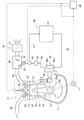
図1は、汎用エンジン10の吸排気ライン31,32と燃料供給ライン40とを模式的に示している。汎用エンジン10は、船外機や作業機等の汎用機に搭載されており、クランクケース11とシリンダブロック12とヘッドカバー13とクランク軸14とピストン15とを含む。シリンダブロック12には、ピストン15が往復動するシリンダ16が設けられている。さらに、汎用エンジン10は、クランク軸14によって駆動する発電機17を備えている。
FIG. 1 schematically shows intake and
ヘッドカバー13には、点火プラグ18が設けられている。さらに、ヘッドカバー13は、吸気口21と排気口22とを有する。吸気口21は、吸気弁23によって開閉される。排気口22は、排気弁24によって開閉される。吸気弁23と排気弁24は、ロッカアームシャフト25により、バルブロッカアーム26を介して開閉駆動される。ロッカアームシャフト25は、カム軸の一種であって、クランク軸14によって駆動される。以下、ロッカアームシャフト25のことを、適宜「カム軸25」と言い換える。
A
吸気口21には、吸気ライン31が接続されている。排気口22には、排気ライン32が接続されている。吸気ライン31は、エアクリーナ33とスロットルボデイ34とインテークマニホールド35とを有する。スロットルボデイ34には、スロットル弁36と電子制御噴射装置37とが設けられている。
An
燃料供給ライン40は、燃料タンク41と、汎用エンジン用ダイヤフラム式燃料ポンプ42と燃料フィルタ43と燃料圧力レギュレータ44と前記電子制御噴射装置37とを有する。汎用エンジン用ダイヤフラム式燃料ポンプ42(以下、単に「燃料ポンプ42」と略称する。)は、カム軸25に設けられたカム25a(カム山25a)によって駆動される、機械式燃料ポンプの一種である。
The
燃料タンク41内の燃料は、燃料吸入配管45によって燃料ポンプ42の吸入口42aに供給される。燃料ポンプ42の吐出口42bから吐出された燃料は、燃料吐出配管46を介して、燃料フィルタ43と燃料圧力レギュレータ44とを通り、電子制御噴射装置37へ供給される。この電子制御噴射装置37によって霧化された燃料は、スロットルボデイ34内に供給されて、燃焼用空気と共に汎用エンジン10の燃焼室19へ供給される。
The fuel in the
燃料ポンプ42から吐出された燃料は脈動している。燃料圧力レギュレータ44は、燃料の吐出圧を平準化するものであり、余分な燃料を戻り配管47を介して燃料タンク41に戻している。
The fuel discharged from the
制御部48は、発電機17から電力を受けており、少なくとも点火プラグ18と電子制御噴射装置37とを制御する。
The
図2及び図3は、「高圧用」の燃料ポンプとして用いられる汎用エンジン用ダイヤフラム式燃料ポンプ42を示している。
2 and 3 show a
この燃料ポンプ42(汎用エンジン用ダイヤフラム式燃料ポンプ42)は、ハウジング50とダイヤフラム60とロッド70とプランジャ80とプランジャ付勢部材91と第1ピン92とを含む。
The fuel pump 42 (
ハウジング50は、第1ハウジング半体51と第2ハウジング半体52との二分割品であり、ボルト止めによって一体化されている。このハウジング50は、ダイヤフラム室53と吸入室54と吐出室55と前記吸入口42aと前記吐出口42bを有する。ダイヤフラム室53は、第1ハウジング半体51と第2ハウジング半体52との間に形成されている。吸入室54と吐出室55と前記吸入口42aと前記吐出口42bとは、第1ハウジング半体51に設けられている。
The
ダイヤフラム60は、第1ハウジング半体51と第2ハウジング半体52との間、つまりダイヤフラム室53に設けられており、このダイヤフラム室53(ハウジング50の内部53)をポンプ室56とエア室57とに区画している。エア室57は、外気に連通している。吸入口42aは、吸入室54と吸入用逆止弁58とを介してポンプ室56に連通している。吐出口42bは、吐出室55と吐出用逆止弁59とを介してポンプ室56に連通している。吸入用逆止弁58は、吸入室54からポンプ室56へ向かう燃料の流れのみを許容する。吐出用逆止弁59は、ポンプ室56から吐出室55へ向かう燃料の流れのみを許容する。
The
ロッド70は、第2ハウジング半体52(ハウジング50)にスライド可能に支持されている。ロッド70の一端部71は、ダイヤフラム60に連結されている。ロッド70の他端部72は、エア室57から第2ハウジング半体52(ハウジング50)の外方へ、つまりカム25aへ向かって突出している。
The
プランジャ80は、ロッド70の他端部72を嵌合可能な筒部81を有した、有底筒状に形成されている。プランジャ80の底82は、カム25aに対向している。このプランジャ80は、ロッド70の他端部72に対して同心上に位置し、且つロッド70に対して相対的にスライド可能に嵌合している。
The
プランジャ付勢部材91は、ロッド70に巻かれた圧縮コイルバネによって構成されている。プランジャ付勢部材91は、プランジャ80をロッド70の他端部72側(カム25a側)へ付勢している。
The
第1ピン92は、ロッド70の他端部72に有している。この第1ピン92は、ロッド70の他端部72の径外方へ延びている。つまり、ロッド70の他端部72には、径方向に貫通したピン嵌合孔73が形成されている。第1ピン92は、ピン嵌合孔73に嵌合されるとともに、ロッド70の径方向の両側へ延びている。
The
プランジャ80の筒部81には、この筒部81を径方向に貫通した貫通孔83が形成されている。この貫通孔83は、第1ピン92が貫通孔83に対してロッド70の長手方向に変位可能な大きさに設定されている。この貫通孔83は、真円状の丸孔によって構成されている。なお、この貫通孔83は、プランジャ80の長手方向に細長い長孔であってもよい。貫通孔83の縁84のなかの、ダイヤフラム60側の縁84aを「一方の縁84a」とし、プランジャ80の底82側の縁84bを「他方の縁84b」とする。一方の縁84aには、第1ピン92が接している。
The
貫通孔83の他方の縁84bと、ロッド70の他端部72の端面74(他端面74)との間には、第1ピン92に平行な第2ピン93を嵌め込み可能な隙間75を有する。この隙間75に第2ピン93が嵌められてなる構成とすることで、ロッド70の他端部72は、第1ピン92と第2ピン93とにより、プランジャ80に対してロッド70の長手方向への移動を規制されている。第1及び第2ピン92,93の長さは、プランジャ80の筒部81の外径以下に設定されることが好ましい。
Between the
高圧用の燃料ポンプ42の作用は、次の通りである。プランジャ80は、カム25aの回転変位に従い、ダイヤフラム60に対して往復動する。プランジャ80にロックされているロッド70は、プランジャ80と共に往復動して、ダイヤフラム60を弾性変位させる。この結果、ポンプ室56の容積が変動することによって、吸入口42aから吸入した燃料を吐出口42bへ吐出する。
The operation of the high-
このように「高圧用」の燃料ポンプとして用いられる汎用エンジン用ダイヤフラム式燃料ポンプ42は、「高圧の燃料を噴射する電子式燃料噴射装置37(図1参照)」に燃料を供給するのに最適である。
As described above, the
図4及び図5は、「低圧用」の燃料ポンプとして用いられる汎用エンジン用ダイヤフラム式燃料ポンプ42を示している。汎用エンジン用ダイヤフラム式燃料ポンプ42が低圧用の燃料ポンプとして用いられる場合には、第1ピン92のみを有し、図1及び図2に示される第2ピン93を有していない。また、この場合には、ダイヤフラム60をエア室57側からポンプ室56へ向かって付勢する「ダイヤフラム用付勢部材100」を設けることになる。その他の構成は、上記図2及び図3に示される高圧用のダイヤフラム式燃料ポンプ42と同じなので、説明を省略する。
4 and 5 show a
低圧用の燃料ポンプ42の作用は、次の通りである。プランジャ80は、カム25aの回転変位に従い、ダイヤフラム60に対して往復動する。プランジャ80がダイヤフラム60側へ変位した場合には、ロッド70は、プランジャ80に対して軸方向にフリーとなる。ロッド70とダイヤフラム60は、ダイヤフラム用付勢部材100の付勢力によって、ポンプ室56側へ弾性変位する。その後、プランジャ80がカム25a側へ変位した場合には、ロッド70とダイヤフラム60は、ダイヤフラム用付勢部材100の付勢力に抗してカム25a側へ引き戻される。この結果、ポンプ室56の容積が変動することによって、吸入口42aから吸入した燃料を吐出口42bへ吐出する。
The operation of the low-
このように「低圧用」の燃料ポンプとして用いられる汎用エンジン用ダイヤフラム式燃料ポンプ42は、「負圧を利用して燃料を霧化するキャブレタ(図示せず)」に燃料を供給するのに最適である。
Thus, the
以上の説明をまとめると、次の通りである。
図2に示されるように、汎用エンジン用ダイヤフラム式燃料ポンプ42は、第1ピン92の他に、この第1ピン92に平行な第2ピン93を有することが可能である。第2ピン93の有無にかかわらず、プランジャ80は、プランジャ付勢部材91によってロッド70の他端部72側へ付勢されている。第1ピン92は、貫通孔83の縁84のなかの、ダイヤフラム側の縁84a(一方の縁84a)に常に接している。
The above description is summarized as follows.
As shown in FIG. 2, the
図4に示されるように、第1ピン92のみを用いた場合には、ロッド70の他端部72は、プランジャ80に対してロッド70の長手方向への移動が可能である。この場合には、ダイヤフラム60をエア室57側からポンプ室56へ向かって付勢する「ダイヤフラム用付勢部材100」を設けることになる。従って、汎用エンジン10のカム25aによって、プランジャ80がダイヤフラム60側へ押し上げられたときに、このダイヤフラム60は、ダイヤフラム用付勢部材100によりポンプ室56へ向かって付勢される。燃料ポンプ42の吐出圧力は、ダイヤフラム用付勢部材100の付勢力に依存した、比較的低圧となる。
As shown in FIG. 4, when only the
一方、図2に示されるように、第1ピン92と第2ピン93の両方を用いた場合には、第2ピン93は、貫通孔83の縁84のなかの、プランジャ80の底82側の縁84b(他方の縁84b)と、ロッド70の他端面74との間に介在し、且つこれらの両者84b,74に接する。つまり、第2ピン93は、貫通孔83の縁84のなかの、他方の縁84bに接している。ロッド70の他端部72は、第1ピン92と第2ピン93とにより、プランジャ80に対してロッド70の長手方向への移動を規制(つまりロック)される。この結果、ロッド70はプランジャ80に直結される。この場合には、前記ダイヤフラム用付勢部材100(図4参照)の有無は任意である。
On the other hand, as shown in FIG. 2, when both the
従って、汎用エンジン10のカム25aによって、プランジャ80がダイヤフラム60側へ押し上げられたときに、このダイヤフラム60はプランジャ80によりポンプ室56へ向かって、強制的に弾性変位させられる。このため、燃料ポンプ42の吐出圧力は、ダイヤフラム用付勢部材100の付勢力に依存しない、比較的高圧となる。
Therefore, when the
このように、第2ピン93(図2参照)の有無によって、燃料ポンプ42の吐出圧力を任意に変更することができる。しかも、第2ピン93の有無を選択するという、簡単な構成によって極めて容易に変更できる。加えて、燃料ポンプ42の吐出圧力を変更しても、この燃料ポンプ42の形状や寸法は、全く同じである。従って、低圧用の燃料ポンプと高圧用の燃料ポンプとを入れ替えるだけで、そのまま使用することができる。このため、汎用エンジン10の燃料供給ライン40において、キャブレータ仕様のラインと電子制御噴射装置仕様のラインとの、変更を容易に行うことができる。
Thus, the discharge pressure of the
加えて、第2ピン93の有無だけによって、1種類の汎用エンジン用ダイヤフラム式燃料ポンプ42を、低圧用と高圧用とに変更できるので、量産効果が高まる。その結果、汎用エンジン用ダイヤフラム式燃料ポンプ42のコストダウンを図ることができる。
In addition, since only one type of
ところで、図2に示されるように、第2ピン93とプランジャ80の内底85との間には、スペーサ94が嵌められることが、より好ましい。このようにすることで、第2ピン93の長手中央部を、スペーサ94を介してプランジャ80の内底85(内底面85)により支持することができる。従って、第2ピン93の曲げ強度を高めることができる。
Incidentally, as shown in FIG. 2, it is more preferable that a
次に、汎用エンジン用ダイヤフラム式燃料ポンプ42の変形例を、図6に基づき説明する。変形例の汎用エンジン用ダイヤフラム式燃料ポンプ42Aは、上記図2及び図3に示される燃料ポンプ42に対して、次の点で相違するだけであり、他の構成については、燃料ポンプ42と同一である。
第1の相違点は、ロッド70の他端面74とプランジャ80の内底85との間には、スペーサ94Aを嵌め込み可能な隙間95を有することである。
第2の相違点は、この隙間95にスペーサ94Aが嵌められてなる構成とすることで、ロッド70の他端部72は、第1ピン92とスペーサ94Aとにより、プランジャ80に対してロッド70の長手方向への移動を規制されていることである。
Next, a modified example of the
The first difference is that there is a
The second difference is that the
変形例では、図6に示されるように、汎用エンジン用ダイヤフラム式燃料ポンプ42は、第1ピン92の他に、スペーサ94Aを有することが可能である。スペーサ94Aの有無にかかわらず、プランジャ80は、プランジャ付勢部材91によってロッド70の他端部72側へ付勢されている。第1ピン92は、貫通孔83の縁84のなかの、ダイヤフラム側の縁84a(一方の縁84a)に常に接している。
In the modification, as shown in FIG. 6, the
図4に示されるように、第1ピン92のみを用いた場合には、ロッド70の他端部72は、プランジャ80に対してロッド70の長手方向への移動が可能である。この場合には、ダイヤフラム60をエア室57側からポンプ室56へ向かって付勢する「ダイヤフラム用付勢部材100」を設けることになる。従って、汎用エンジン10のカム25aによって、プランジャ80がダイヤフラム60側へ押し上げられたときに、このダイヤフラム60は、ダイヤフラム用付勢部材100によりポンプ室56へ向かって付勢される。燃料ポンプ42の吐出圧力は、ダイヤフラム用付勢部材100の付勢力に依存した、比較的低圧となる。
As shown in FIG. 4, when only the
一方、図2に示されるように、第1ピン92とスペーサ94Aの両方を用いた場合には、スペーサ94Aは、ロッド70の他端面74とプランジャ80の内底85との間に介在し、且つこれらの両者に接する。ロッド70の他端部72は、第1ピン92とスペーサ94Aとにより、プランジャ80に対してロッド70の長手方向への移動を規制(つまりロック)される。この結果、ロッド70はプランジャ80に直結される。この場合には、前記ダイヤフラム用付勢部材100(図4参照)の有無は任意である。
On the other hand, as shown in FIG. 2, when both the
従って、汎用エンジン10のカム25aによって、プランジャ80がダイヤフラム60側へ押し上げられたときに、このダイヤフラム60はプランジャ80によりポンプ室56へ向かって、強制的に弾性変位させられる。このため、燃料ポンプ42の吐出圧力は、ダイヤフラム用付勢部材100の付勢力に依存しない、比較的高圧となる。
Therefore, when the
このように、スペーサ94Aの有無によって、燃料ポンプ42の吐出圧力を任意に変更することができる。しかも、スペーサ94Aの有無を選択するという、簡単な構成によって極めて容易に変更できる。加えて、燃料ポンプ42の吐出圧力を変更しても、この燃料ポンプ42の形状や寸法は、全く同じである。従って、低圧用の燃料ポンプと高圧用の燃料ポンプとを入れ替えるだけで、そのまま使用することができる。このため、汎用エンジン10の燃料供給ライン40において、キャブレータ仕様のラインと電子制御噴射装置仕様のラインとの、変更を容易に行うことができる。
Thus, the discharge pressure of the
加えて、スペーサ94Aの有無だけによって、1種類の汎用エンジン用ダイヤフラム式燃料ポンプ42を、低圧用と高圧用とに変更できるので、量産効果が高まる。その結果、汎用エンジン用ダイヤフラム式燃料ポンプ42のコストダウンを図ることができる。
In addition, since only one type of general-purpose engine
本発明の汎用エンジン用ダイヤフラム式燃料ポンプ42,42Aは、船外機や作業機等の汎用機の汎用エンジンに採用するのに好適である。 The diaphragm fuel pumps 42 and 42A for general-purpose engines of the present invention are suitable for use in general-purpose engines for general-purpose machines such as outboard motors and work machines.
42 汎用エンジン用ダイヤフラム式燃料ポンプ
50 ハウジング
53 ダイヤフラム室(ハウジングの内部)
56 ポンプ室
57 エア室
60 ダイヤフラム
70 ロッド
71 一端部
72 他端部
74 他端面
75 隙間
80 プランジャ
81 筒部
82 プランジャの底
83 貫通孔
84 貫通孔の縁
84a ダイヤフラム側の縁(一方の縁)
84b プランジャの底側の縁(他方の縁)
85 プランジャの内底
91 プランジャ付勢部材
92 第1ピン
93 第2ピン
100 ダイヤフラム用付勢部材
94 スペーサ
94A スペーサ
95 隙間
42 Diaphragm fuel pump for general-
56
84b Bottom edge of the plunger (the other edge)
85 Inner bottom of
Claims (3)
このハウジングの内部をポンプ室とエア室とに区画したダイヤフラムと、
このダイヤフラムに一端部を連結されるとともに、他端部を前記エア室から前記ハウジングの外方へ突出しており、前記ハウジングにスライド可能に支持されたロッドと、
このロッドの他端部に対して同心上に位置し、且つ前記ロッドに対してスライド可能に嵌合したプランジャと、
このプランジャを前記ロッドの他端部側へ付勢したプランジャ付勢部材とを含む汎用エンジン用ダイヤフラム式燃料ポンプにおいて、
前記ロッドの他端部は、この他端部の径外方へ延びた第1ピンを有し、
前記プランジャは、前記ロッドの他端部を嵌合可能な筒部を有した、有底筒状に形成されており、
前記筒部には、この筒部を径方向に貫通した貫通孔が形成され、
この貫通孔は、前記第1ピンが前記貫通孔に対して前記ロッドの長手方向に変位可能な大きさに設定され、
前記貫通孔の縁のなかの、前記ダイヤフラム側の縁を一方の縁とし、前記プランジャの底側の縁を他方の縁とし、
前記一方の縁には、前記第1ピンが接しており、
前記貫通孔の前記他方の縁と前記ロッドの他端面との間には、前記第1ピンに平行な第2ピンを嵌め込み可能な隙間を有し、
この隙間に前記第2ピンが嵌められてなる構成とすることで、前記ロッドの他端部は、前記第1ピンと前記第2ピンとにより、前記プランジャに対して前記ロッドの長手方向への移動を規制されていることを特徴とする汎用エンジン用ダイヤフラム式燃料ポンプ。 A housing;
A diaphragm that partitions the interior of the housing into a pump chamber and an air chamber;
One end of the diaphragm is connected to the diaphragm, and the other end projects from the air chamber to the outside of the housing. The rod is slidably supported by the housing;
A plunger located concentrically with respect to the other end of the rod and slidably fitted to the rod;
In the diaphragm fuel pump for general-purpose engines, including a plunger urging member that urges the plunger toward the other end of the rod.
The other end of the rod has a first pin extending radially outward of the other end,
The plunger is formed in a bottomed cylindrical shape having a cylindrical portion capable of fitting the other end of the rod.
The cylindrical portion is formed with a through-hole penetrating the cylindrical portion in the radial direction,
The through hole is set to a size such that the first pin can be displaced in the longitudinal direction of the rod with respect to the through hole.
Of the edges of the through hole, the diaphragm side edge is one edge, and the bottom edge of the plunger is the other edge,
The first pin is in contact with the one edge,
Between the other edge of the through hole and the other end surface of the rod, there is a gap into which a second pin parallel to the first pin can be fitted,
By adopting a configuration in which the second pin is fitted in the gap, the other end of the rod is moved in the longitudinal direction of the rod with respect to the plunger by the first pin and the second pin. A diaphragm-type fuel pump for general-purpose engines, which is regulated.
このハウジングの内部をポンプ室とエア室とに区画したダイヤフラムと、
このダイヤフラムに一端部を連結されるとともに、他端部を前記エア室から前記ハウジングの外方へ突出しており、前記ハウジングにスライド可能に支持されたロッドと、
このロッドの他端部に対して同心上に位置し、且つ前記ロッドに対してスライド可能に嵌合したプランジャと、
このプランジャを前記ロッドの他端部側へ付勢したプランジャ付勢部材とを含む汎用エンジン用ダイヤフラム式燃料ポンプにおいて、
前記ロッドの他端部は、この他端部の径外方へ延びた第1ピンを有し、
前記プランジャは、前記ロッドの他端部を嵌合可能な筒部を有した、有底筒状に形成されており、
前記筒部には、この筒部を径方向に貫通した貫通孔が形成され、
この貫通孔は、前記第1ピンが前記貫通孔に対して前記ロッドの長手方向に変位可能な大きさに設定され、
前記貫通孔の縁のなかの、前記ダイヤフラム側の縁には、前記第1ピンが接しており、
前記ロッドの他端面と前記プランジャの内底との間には、スペーサを嵌め込み可能な隙間を有し、
この隙間に前記スペーサが嵌められてなる構成とすることで、前記ロッドの他端部は、前記第1ピンと前記スペーサとにより、前記プランジャに対して前記ロッドの長手方向への移動を規制されていることを特徴とする汎用エンジン用ダイヤフラム式燃料ポンプ。 A housing;
A diaphragm that partitions the interior of the housing into a pump chamber and an air chamber;
One end of the diaphragm is connected to the diaphragm, and the other end projects from the air chamber to the outside of the housing. The rod is slidably supported by the housing;
A plunger located concentrically with respect to the other end of the rod and slidably fitted to the rod;
In the diaphragm fuel pump for general-purpose engines, including a plunger urging member that urges the plunger toward the other end of the rod.
The other end of the rod has a first pin extending radially outward of the other end,
The plunger is formed in a bottomed cylindrical shape having a cylindrical portion capable of fitting the other end of the rod.
The cylindrical portion is formed with a through-hole penetrating the cylindrical portion in the radial direction,
The through hole is set to a size such that the first pin can be displaced in the longitudinal direction of the rod with respect to the through hole.
The first pin is in contact with the diaphragm side edge of the through hole.
Between the other end surface of the rod and the inner bottom of the plunger, there is a gap into which a spacer can be fitted,
By adopting a configuration in which the spacer is fitted in the gap, the other end of the rod is restricted from moving in the longitudinal direction of the rod with respect to the plunger by the first pin and the spacer. A diaphragm fuel pump for general-purpose engines.
Priority Applications (2)
| Application Number | Priority Date | Filing Date | Title |
|---|---|---|---|
| JP2016049628A JP6591319B2 (en) | 2016-03-14 | 2016-03-14 | Diaphragm fuel pump for general-purpose engines |
| US15/454,467 US10156230B2 (en) | 2016-03-14 | 2017-03-09 | Diaphragm type fuel pump for general purpose engine |
Applications Claiming Priority (1)
| Application Number | Priority Date | Filing Date | Title |
|---|---|---|---|
| JP2016049628A JP6591319B2 (en) | 2016-03-14 | 2016-03-14 | Diaphragm fuel pump for general-purpose engines |
Publications (2)
| Publication Number | Publication Date |
|---|---|
| JP2017166329A true JP2017166329A (en) | 2017-09-21 |
| JP6591319B2 JP6591319B2 (en) | 2019-10-16 |
Family
ID=59786375
Family Applications (1)
| Application Number | Title | Priority Date | Filing Date |
|---|---|---|---|
| JP2016049628A Expired - Fee Related JP6591319B2 (en) | 2016-03-14 | 2016-03-14 | Diaphragm fuel pump for general-purpose engines |
Country Status (2)
| Country | Link |
|---|---|
| US (1) | US10156230B2 (en) |
| JP (1) | JP6591319B2 (en) |
Cited By (1)
| Publication number | Priority date | Publication date | Assignee | Title |
|---|---|---|---|---|
| CN110388294A (en) * | 2018-04-16 | 2019-10-29 | 泰凯气化器株式会社 | Fuel supply system |
Families Citing this family (1)
| Publication number | Priority date | Publication date | Assignee | Title |
|---|---|---|---|---|
| EP4130471B1 (en) * | 2021-08-03 | 2024-04-10 | Idromeccanica Bertolini S.p.A. | Reciprocation pump |
Family Cites Families (4)
| Publication number | Priority date | Publication date | Assignee | Title |
|---|---|---|---|---|
| US6171081B1 (en) * | 1998-02-17 | 2001-01-09 | Keihin Corporation | Fuel pump assembly |
| JP2000282994A (en) * | 1999-03-30 | 2000-10-10 | Mikuni Adec Corp | Fuel pump |
| JP4439723B2 (en) * | 2000-12-28 | 2010-03-24 | 株式会社ミクニ | Fuel pump |
| JP4563613B2 (en) | 2001-05-10 | 2010-10-13 | 本田技研工業株式会社 | Fuel pump mounting structure for outboard engine |
-
2016
- 2016-03-14 JP JP2016049628A patent/JP6591319B2/en not_active Expired - Fee Related
-
2017
- 2017-03-09 US US15/454,467 patent/US10156230B2/en active Active
Cited By (1)
| Publication number | Priority date | Publication date | Assignee | Title |
|---|---|---|---|---|
| CN110388294A (en) * | 2018-04-16 | 2019-10-29 | 泰凯气化器株式会社 | Fuel supply system |
Also Published As
| Publication number | Publication date |
|---|---|
| JP6591319B2 (en) | 2019-10-16 |
| US10156230B2 (en) | 2018-12-18 |
| US20170260975A1 (en) | 2017-09-14 |
Similar Documents
| Publication | Publication Date | Title |
|---|---|---|
| US8701631B2 (en) | Pressure relief valve and high pressure pump with such valve | |
| US10876509B2 (en) | High-pressure fuel pump | |
| US10941740B2 (en) | High-pressure fuel pump having a piston, a damper, and a pressure relief valve having a valve body and a spring | |
| CN109268180A (en) | A kind of diesel electric-controlled high-pressure common rail oil feed pump | |
| JP6591319B2 (en) | Diaphragm fuel pump for general-purpose engines | |
| JP2010180775A (en) | Fuel supply system for engine | |
| JP2017529487A (en) | Pump unit for supplying fuel, preferably diesel oil, to an internal combustion engine | |
| US8608456B2 (en) | High pressure pump | |
| US9109558B2 (en) | Fuel pump | |
| JP4814657B2 (en) | 2-cycle engine | |
| ATE417200T1 (en) | HIGH PRESSURE PUMP FOR A FUEL INJECTION DEVICE OF AN INTERNAL COMBUSTION ENGINE | |
| JP5529681B2 (en) | Constant residual pressure valve | |
| US10094349B2 (en) | Fluid valve assembly | |
| US6966301B2 (en) | Accumulator fuel system | |
| JP2010196687A (en) | High-pressure pump | |
| CN108071535B (en) | Fuel supply pump | |
| CN107614866A (en) | engine | |
| JP6776963B2 (en) | High pressure pump | |
| KR20110062122A (en) | High pressure fuel pump | |
| JP2007315254A (en) | Mixture generator | |
| JP2018059436A (en) | High pressure pump device and fuel supply system | |
| US8863725B2 (en) | Apparatus for reducing pumping loss and engine including the same | |
| KR20170014831A (en) | High presure fuel pump for direct injection type gasoline engine | |
| JP6520650B2 (en) | High pressure pump | |
| JP2007009750A (en) | Fuel pump seal structure and fuel pump having the seal structure |
Legal Events
| Date | Code | Title | Description |
|---|---|---|---|
| RD03 | Notification of appointment of power of attorney |
Free format text: JAPANESE INTERMEDIATE CODE: A7423 Effective date: 20160411 |
|
| A621 | Written request for application examination |
Free format text: JAPANESE INTERMEDIATE CODE: A621 Effective date: 20181127 |
|
| A977 | Report on retrieval |
Free format text: JAPANESE INTERMEDIATE CODE: A971007 Effective date: 20190822 |
|
| TRDD | Decision of grant or rejection written | ||
| A01 | Written decision to grant a patent or to grant a registration (utility model) |
Free format text: JAPANESE INTERMEDIATE CODE: A01 Effective date: 20190910 |
|
| A61 | First payment of annual fees (during grant procedure) |
Free format text: JAPANESE INTERMEDIATE CODE: A61 Effective date: 20190918 |
|
| R150 | Certificate of patent or registration of utility model |
Ref document number: 6591319 Country of ref document: JP Free format text: JAPANESE INTERMEDIATE CODE: R150 |
|
| LAPS | Cancellation because of no payment of annual fees |