JP2017163784A - Stator of rotary electric machine - Google Patents
Stator of rotary electric machine Download PDFInfo
- Publication number
- JP2017163784A JP2017163784A JP2016048338A JP2016048338A JP2017163784A JP 2017163784 A JP2017163784 A JP 2017163784A JP 2016048338 A JP2016048338 A JP 2016048338A JP 2016048338 A JP2016048338 A JP 2016048338A JP 2017163784 A JP2017163784 A JP 2017163784A
- Authority
- JP
- Japan
- Prior art keywords
- stator
- refrigerant
- rotating electrical
- electrical machine
- coil
- Prior art date
- Legal status (The legal status is an assumption and is not a legal conclusion. Google has not performed a legal analysis and makes no representation as to the accuracy of the status listed.)
- Granted
Links
- 239000003507 refrigerant Substances 0.000 claims abstract description 118
- 239000002826 coolant Substances 0.000 claims description 9
- 238000007599 discharging Methods 0.000 claims description 3
- 230000004048 modification Effects 0.000 description 6
- 238000012986 modification Methods 0.000 description 6
- 239000004020 conductor Substances 0.000 description 2
- 230000008602 contraction Effects 0.000 description 2
- 238000001816 cooling Methods 0.000 description 2
- 239000000463 material Substances 0.000 description 2
- 239000011347 resin Substances 0.000 description 2
- 229920005989 resin Polymers 0.000 description 2
- 238000005452 bending Methods 0.000 description 1
- 230000005540 biological transmission Effects 0.000 description 1
- 239000012530 fluid Substances 0.000 description 1
- 230000020169 heat generation Effects 0.000 description 1
- 230000000149 penetrating effect Effects 0.000 description 1
- 230000002093 peripheral effect Effects 0.000 description 1
- 238000005507 spraying Methods 0.000 description 1
- 230000009466 transformation Effects 0.000 description 1
Images


Classifications
-
- H—ELECTRICITY
- H02—GENERATION; CONVERSION OR DISTRIBUTION OF ELECTRIC POWER
- H02K—DYNAMO-ELECTRIC MACHINES
- H02K3/00—Details of windings
- H02K3/04—Windings characterised by the conductor shape, form or construction, e.g. with bar conductors
- H02K3/24—Windings characterised by the conductor shape, form or construction, e.g. with bar conductors with channels or ducts for cooling medium between the conductors
-
- H—ELECTRICITY
- H02—GENERATION; CONVERSION OR DISTRIBUTION OF ELECTRIC POWER
- H02K—DYNAMO-ELECTRIC MACHINES
- H02K9/00—Arrangements for cooling or ventilating
- H02K9/19—Arrangements for cooling or ventilating for machines with closed casing and closed-circuit cooling using a liquid cooling medium, e.g. oil
- H02K9/197—Arrangements for cooling or ventilating for machines with closed casing and closed-circuit cooling using a liquid cooling medium, e.g. oil in which the rotor or stator space is fluid-tight, e.g. to provide for different cooling media for rotor and stator
-
- H—ELECTRICITY
- H02—GENERATION; CONVERSION OR DISTRIBUTION OF ELECTRIC POWER
- H02K—DYNAMO-ELECTRIC MACHINES
- H02K9/00—Arrangements for cooling or ventilating
- H02K9/19—Arrangements for cooling or ventilating for machines with closed casing and closed-circuit cooling using a liquid cooling medium, e.g. oil
Landscapes
- Engineering & Computer Science (AREA)
- Power Engineering (AREA)
- Motor Or Generator Cooling System (AREA)
Abstract
Description
本発明は、ステータコイルを効果的に冷却可能な回転電機のステータに関する。 The present invention relates to a stator for a rotating electrical machine capable of effectively cooling a stator coil.
従来より、電気自動車やハイブリッド自動車等の回転電機を動力源として備えた車両が開発されている。近年では、駆動用の回転電機が高出力化しており、ステータコイルの温度上昇に伴って回転電機の性能が劣化するため、ステータコイルを冷却するなどの対策が検討されている。 Conventionally, vehicles equipped with a rotating electrical machine such as an electric vehicle and a hybrid vehicle as a power source have been developed. In recent years, the output of a rotating electric machine for driving has been increased, and the performance of the rotating electric machine has deteriorated as the temperature of the stator coil has increased. Therefore, measures such as cooling the stator coil have been studied.
特許文献1の回転電機では、回転電機内のコイルエンド外周から上方に離間した位置に樋を設け、樋の底面に設けられた複数の冷却液供給口からガイドを伝いコイルエンドに冷媒を供給することが記載されている。
In the rotating electrical machine disclosed in
特許文献2の回転電機では、冷媒分配経路が形成されている冷媒分配部をコイルエンドの冷媒供給対象部位に対して上方に配置することが記載されている。
In the rotating electrical machine of
特許文献3の回転電機では、ステータが固定される外筒リングの外周面に、外筒リングの円周方向からコイルエンドの方向に向かって冷媒を流すガイドベーンを設けることが記載されている。 In the rotating electric machine of Patent Document 3, it is described that a guide vane for flowing a refrigerant from the circumferential direction of the outer cylinder ring toward the coil end is provided on the outer circumferential surface of the outer cylinder ring to which the stator is fixed.
しかしながら、特許文献1及び特許文献2に記載の回転電機では、樋又は冷媒分配経路がコイルエンドの上方に配置されているため、下部に位置するステータコイルまで冷媒を導くことが難しく、下部に位置するステータコイルで部分的な発熱を生じてしまう虞があった。
However, in the rotating electrical machines described in
また、特許文献3に記載の回転電機では、ステータが固定される外筒リングの外周面にガイドベーンを形成するため、回転電機の外形寸法が大きくなり搭載性が悪化する虞があった。 Further, in the rotating electrical machine described in Patent Document 3, since the guide vanes are formed on the outer peripheral surface of the outer cylindrical ring to which the stator is fixed, the outer dimensions of the rotating electrical machine may be increased and the mountability may be deteriorated.
本発明は、前述した課題に鑑みてなされたものであり、その目的は、回転電機の外形寸法に影響を与えずに、下部に位置するステータコイルまで冷媒を導くことのできる回転電機のステータを提供することにある。 The present invention has been made in view of the above-described problems, and an object of the present invention is to provide a stator for a rotating electrical machine capable of guiding a refrigerant to a stator coil located below without affecting the outer dimensions of the rotating electrical machine. It is to provide.
上記目的を達成するために、請求項1に係る発明は、
周方向に所定の間隔で複数のスロット(例えば、後述の実施形態におけるスロット14)が形成されたステータコア(例えば、後述の実施形態におけるステータコア13)と、
前記スロットに挿通されたステータコイル(例えば、後述の実施形態におけるステータコイル15)と、を備え、冷媒により冷却される回転電機(例えば、後述の実施形態における回転電機10)のステータ(例えば、後述の実施形態におけるステータ12)であって、
前記ステータコアの端面(例えば、後述の実施形態における前面13F)から突出する前記ステータコイルの少なくとも一方のコイルエンド(例えば、後述の実施形態におけるコイルエンド30F)と前記ステータコアの前記端面との間には、冷媒を周方向に導く冷媒ガイド(例えば、後述の実施形態における冷媒ガイド50)が設けられている。
In order to achieve the above object, the invention according to
A stator core (for example, a
A stator coil (for example, a
Between at least one coil end (for example,
請求項2に係る発明は、請求項1の構成に加えて、
前記冷媒ガイドは、前記ステータコイルの全周に亘って連続するリング形状を有する。
In addition to the configuration of
The refrigerant guide has a ring shape that is continuous over the entire circumference of the stator coil.
請求項3に係る発明は、請求項1又は2の構成に加えて、
前記冷媒ガイドには、径方向に突出する固定片(例えば、後述の実施形態における固定片55)が設けられ、
前記固定片は、前記コイルエンドと前記ステータコアの前記端面との間の隙間に挟み込まれている。
In addition to the configuration of
The refrigerant guide is provided with a fixing piece (for example, a
The fixed piece is sandwiched in a gap between the coil end and the end face of the stator core.
請求項4に係る発明は、請求項1〜3のいずれか1項の構成に加えて、
前記冷媒ガイドは、少なくとも一部の断面において、凸部(例えば、後述の実施形態における凸部52)又は凹部(例えば、後述の実施形態における凹部51)を有する。
In addition to the structure of any one of Claims 1-3, the invention which concerns on Claim 4
The refrigerant guide has a convex portion (for example, a
請求項5に係る発明は、請求項1〜4のいずれか1項の構成に加えて、
前記冷媒ガイドは、冷媒を導入する冷媒導入孔(例えば、後述の実施形態における冷媒導入孔57)と冷媒を排出する冷媒導出孔(例えば、後述の実施形態における冷媒導出孔58)とが形成された中空体から構成されている。
In addition to the structure of any one of Claims 1-4, the invention which concerns on Claim 5 is
The refrigerant guide is formed with a refrigerant introduction hole (for example, a
請求項6に係る発明は、請求項1〜5のいずれか1項の構成に加えて、
前記冷媒ガイドは、拡径可能な弾性体から構成されている。
In addition to the structure of any one of Claims 1-5, the invention which concerns on Claim 6 is
The refrigerant guide is made of an elastic body capable of expanding its diameter.
請求項7に係る発明は、請求項1〜6のいずれか1項の構成に加えて、
前記冷媒ガイドは、捻られた状態で取り付けられている。
In addition to the structure of any one of Claims 1-6, the invention which concerns on Claim 7 is
The refrigerant guide is attached in a twisted state.
請求項1に記載の発明によれば、ステータコアの端面から突出するコイルエンドとステータコアの端面との間に冷媒ガイドが設けられ、ステータに供給された冷媒が冷媒ガイドにより周方向に導かれるので、下部に位置するステータコイルまで冷媒を導くことができ、コイル温度が局所的に高くなるのを抑制できる。 According to the first aspect of the present invention, the refrigerant guide is provided between the coil end protruding from the end face of the stator core and the end face of the stator core, and the refrigerant supplied to the stator is guided in the circumferential direction by the refrigerant guide. The refrigerant can be guided to the stator coil located at the lower portion, and the coil temperature can be suppressed from becoming locally high.
請求項2に記載の発明によれば、特別な固定部を要せず冷媒ガイドをステータコイルの周囲に固定することができる。また、冷媒が届きにくいステータコアの下部に位置するステータコイルにも冷媒を供給することができる。
According to invention of
請求項3に記載の発明によれば、冷媒ガイドの固定片をコイルエンドとステータコアの端面との間の隙間に挟み込むことで、冷媒ガイドをステータコイルの周囲により確実に固定することができる。 According to the third aspect of the present invention, the refrigerant guide can be more reliably fixed around the stator coil by sandwiching the fixing piece of the refrigerant guide in the gap between the coil end and the end face of the stator core.
請求項4に記載の発明によれば、凸部又は凹部により冷媒ガイドの冷媒を導く機能を高めることができる。 According to invention of Claim 4, the function which guide | induces the refrigerant | coolant of a refrigerant | coolant guide by a convex part or a recessed part can be improved.
請求項5に記載の発明によれば、冷媒導出孔の位置を調整することで所望の位置に確実に冷媒を供給することができる。 According to the fifth aspect of the present invention, the refrigerant can be reliably supplied to a desired position by adjusting the position of the refrigerant outlet hole.
請求項6に記載の発明によれば、冷媒ガイドを拡径させることで、予めステータコイルが取り付けられていても、これを跨いで容易に冷媒ガイドを取り付けることができる。即ち、ステータコアに対し冷媒ガイドを位置決めした状態でステータコイルを取り付ける場合に比べて、冷媒ガイドを後付けできるので、冷媒ガイドの組み付け性が良い。また、拡径された冷媒ガイドの収縮力を用いて、冷媒ガイドをステータコイルの周囲に固定することができる。 According to the sixth aspect of the present invention, the refrigerant guide can be easily attached across the stator coil by expanding the diameter of the refrigerant guide even if the stator coil is previously attached. That is, since the refrigerant guide can be retrofitted compared to the case where the stator coil is attached with the refrigerant guide positioned relative to the stator core, the assembly of the refrigerant guide is good. Further, the refrigerant guide can be fixed around the stator coil by using the contraction force of the expanded refrigerant guide.
請求項7に記載の発明によれば、冷媒ガイドが捻られた状態で取り付けられているため、ねじりにより冷媒が誘導され所望の位置に積極的に冷媒を供給することができる。 According to the invention described in claim 7, since the refrigerant guide is attached in a twisted state, the refrigerant is guided by twisting and can be positively supplied to a desired position.
以下、本発明の回転電機のステータの一実施形態を、添付図面に基づいて説明する。なお、図面は符号の向きに見るものとする。 Hereinafter, an embodiment of a stator for a rotating electrical machine according to the present invention will be described with reference to the accompanying drawings. The drawings are viewed in the direction of the reference numerals.
図1〜図4に示すように、回転電機10のステータ12は、ハウジング11内に収容され、ステータ12の内側には、図示しないロータが回転自在に配置されている。
As shown in FIGS. 1 to 4, the
ステータ12は、軸方向に貫通する複数のスロット14(図3参照。)が周方向に所定の間隔で配置されたステータコア13と、スロット14に収容される複数相(例えば、U相、V相、W相)のステータコイル15と、を備える。
The
ステータコア13は、径方向に突出する複数の取付け部17aに設けられたボルト穴17bにボルト16を挿通させ、ハウジング11に固定されている。
The
回転電機10のステータコイル15は、セグメントコンダクタ型コイルであり、図5に示すように、一対の脚部21と、両脚部21を一方の端部で接続する連結部22とからなる複数(本実施形態では4本)の略U字状のコイルセグメント20を1列に整列させて1つの束として、それぞれの脚部21を各スロット14に挿入し、スロット14から突出した脚部21の突出部分を周方向に折り曲げて対応するもの同士を接合して形成される。ステータコア13の軸方向両側には、それぞれコイルエンド30が突出して形成されている。即ち、スロット14から脚部21が突出するステータコア13の後面13R側には、コイルエンド30Rが形成され、これとは反対側となる連結部22が配置されるステータコア13の前面13F側には、コイルエンド30Fが形成される。
The
ステータコイル15のコイルエンド30Fは、図4に示すように、複数のコイルセグメント20の連結部22が周方向に連続し、且つ、周方向で隣り合う連結部22同士が軸方向から見て部分的に重なるように配置されている。また、連結部22はスロット14の外径側に突出し、ステータコア13の前面13Fとコイルエンド30Fとの間には、周方向に連続した溝部40が例えば設けられる。
As shown in FIG. 4, the
図2に示すように、ステータコア13の上方には、ステータコイル15に冷媒を供給するための少なくとも1本の冷媒管19が軸方向に延設されている。冷媒管19には、溝部40の鉛直方向上方位置に冷媒吐出孔18が設けられている。冷媒吐出孔18は、不図示の冷媒供給装置から供給されるATF(Automatic Transmission Fluid)などの冷媒を、溝部40の上方から所定の位置のコイルエンド30F(例えば、最上部に位置するコイルエンド30F)に吐出(滴下、噴射を含む。)してステータコイル15を冷却する。
As shown in FIG. 2, at least one
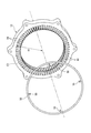
ステータコア13の前面13Fとコイルエンド30Fの連結部22との間には、ステータコイル15の全周に亘って連続するリング形状を有する冷媒ガイド50が配置されている。例として記載した溝部40が形成されていれば、より冷媒ガイド50をこの溝部40に位置決めし易くなるが、溝部40が無くとも適切に配置が可能である。
Between the
冷媒ガイド50は、樹脂やゴム等の非磁性体から構成され、スロット14の外径側端部を結んだ円周C1の径寸法d1(図2、図3参照。)以上、連結部22の最外径部を結んだ円周C2の径寸法d2(図1、図2参照。)以下の径寸法を有する。冷媒ガイド50の断面形状は、例えば、図6(a)に示すように円形状でもよく、多角形状でもよい。多角形状としては、例えば図6(b)に示すように、正方形の四隅が小さい正方形によって切り欠かれた凹部51が設けられているもの、図6(c)に示すように、正七角形の各辺に正三角形状の凸部52が設けられて、隣り合う凸部52間が凹部51となっているもの等でもよい。図1〜図10に示す例では冷媒ガイド50は円断面となっているが、図6(b)及び図6(c)のような凸部52又は凹部51を冷媒ガイド50に形成することで、冷媒ガイド50の冷媒を導く機能を高めることができる。特に、凹部51が設けられた冷媒ガイド50が捻られた状態で溝部40に配置されることで、所望の位置に積極的に冷媒を供給することができる。
The
冷媒ガイド50がゴム等の弾性体から構成されている場合、冷媒ガイド50を拡径させることで、予めステータコイル15が取り付けられていても、これを跨いでステータコア13の溝部40に容易に冷媒ガイド50を取り付けることができる。即ち、ステータコア13に対し冷媒ガイド50を位置決めした状態でステータコイル15を取り付ける場合に比べて、冷媒ガイド50を後付けできるので、冷媒ガイド50の組み付け性が良い。また、拡径された冷媒ガイド50の収縮力を用いて、冷媒ガイド50をステータコイル15の周囲に固定することができる。
When the
一方、冷媒ガイド50が樹脂等の非弾性体から構成されている場合、コイルエンド30Fの前面13Fに予め冷媒ガイド50を配置し、冷媒ガイド50をコイルエンド30Fの前面13Fに位置決めした状態でステータコア13にステータコイル15を組み付けることで、ステータコア13の前面13Fとコイルエンド30Fの連結部22との間に形成された溝部40に冷媒ガイド50が配置される。
On the other hand, when the
また、第1変形例として、冷媒ガイド50が非弾性体の場合、冷媒ガイド50には、少なくとも1つ以上の固定片55が設けられていることが好ましい。図7に示す例では、周方向に所定の間隔(90°)で4つの固定片55が径方向内方に突出するように形成されている。図8に示すように、冷媒ガイド50の固定片55をコイルエンド30Fとステータコア13の前面13Fとの間の隙間に挟み込むことで、冷媒ガイド50をステータコイル15の周囲により確実に固定することができる。なお、複数の固定片55のうちのいくつかを径方向外方に突出するように形成し、固定片55を捻ってコイルエンド30Fとステータコア13の前面13Fとの間の隙間に挟み込むことで、冷媒ガイド50が捻られた状態で溝部40に配置されるようにしてもよい。
As a first modification, when the
また、第2変形例として、冷媒ガイド50が非弾性体の場合、冷媒ガイド50を中空状として、冷媒管19の冷媒吐出孔18に対応するように、冷媒導入孔57を設けるとともに、所定の周方向位置(本実施形態では45°間隔)にコイルエンド30Fに向かって複数の冷媒導出孔58を設けることで、冷媒導入孔57と複数の冷媒導出孔58とが中空状の冷媒ガイド50内の環状流路59で接続され、所望の位置に冷媒を供給することができる。
As a second modification, when the
以上説明したように、本実施形態に係る回転電機10のステータ12によれば、ステータコア13の一端面である前面13Fから突出するコイルエンド30Fとステータコア13の前面13Fとの間に冷媒ガイド50が設けられ、ステータ12に供給された冷媒が冷媒ガイド50により周方向に導かれるので、下部に位置するステータコイル15まで冷媒を導くことができ、コイル温度が局所的に高くなるのを抑制できる。
As described above, according to the
また、冷媒ガイド50は、ステータコイル15の全周に亘って連続するリング形状を有するので、特別な固定部を要せず冷媒ガイド50をステータコイル15の周囲に固定することができる。また、冷媒が届きにくいステータコア13の下部に位置するステータコイル15にも冷媒を供給することができる。
Further, since the
尚、本発明は、前述した各実施形態に限定されるものではなく、適宜、変形、改良、等が可能である。
上記実施形態は、ステータコイル15として、セグメントコンダクタ型コイルを例示したが、これに限らず、各スロット間のティースにコイルが分割して巻回された分割コイルでもよく、一般的な連続巻のコイルでもよい。
In addition, this invention is not limited to each embodiment mentioned above, A deformation | transformation, improvement, etc. are possible suitably.
In the above embodiment, the segment conductor type coil is exemplified as the
また、冷媒ガイド50は、必ずしもリング形状である必要はなく、一部が切り欠かれた円弧形状でもよい。
また、ステータコア13の前面13Fと後面13Rの両側にそれぞれ冷媒ガイド50を設けてもよい。
The
Further, the refrigerant guides 50 may be provided on both sides of the
10 回転電機
12 ステータ
13 ステータコア
13F 前面(端面)
14 スロット
15 ステータコイル
30F コイルエンド
51 凹部
52 凸部
55 固定片
57 冷媒導入孔
58 冷媒導出孔
10 Rotating
14
Claims (7)
前記スロットに挿通されたステータコイルと、を備え、冷媒により冷却される回転電機のステータであって、
前記ステータコアの端面から突出する前記ステータコイルの少なくとも一方のコイルエンドと前記ステータコアの前記端面との間には、冷媒を周方向に導く冷媒ガイドが設けられている、回転電機のステータ。 A stator core having a plurality of slots formed at predetermined intervals in the circumferential direction;
A stator coil inserted into the slot, and a stator of a rotating electrical machine cooled by a refrigerant,
A stator for a rotating electrical machine, wherein a refrigerant guide for guiding a refrigerant in a circumferential direction is provided between at least one coil end of the stator coil protruding from an end face of the stator core and the end face of the stator core.
前記冷媒ガイドは、前記ステータコイルの全周に亘って連続するリング形状を有する、回転電機のステータ。 A stator for a rotating electrical machine according to claim 1,
The said refrigerant | coolant guide is a stator of a rotary electric machine which has a ring shape continuous over the perimeter of the said stator coil.
前記冷媒ガイドには、径方向に突出する固定片が設けられ、
前記固定片は、前記コイルエンドと前記ステータコアの前記端面との間の隙間に挟み込まれている、回転電機のステータ。 A stator for a rotating electrical machine according to claim 1 or 2,
The refrigerant guide is provided with a fixed piece protruding in a radial direction,
The stator of the rotating electrical machine, wherein the fixed piece is sandwiched in a gap between the coil end and the end face of the stator core.
前記冷媒ガイドは、少なくとも一部の断面において、凸部又は凹部を有する、回転電機のステータ。 A stator for a rotating electrical machine according to any one of claims 1 to 3,
The refrigerant guide has a convex portion or a concave portion in at least a part of a cross section thereof.
前記冷媒ガイドは、冷媒を導入する冷媒導入孔と冷媒を排出する冷媒導出孔とが形成された中空体から構成されている、回転電機のステータ。 A stator for a rotating electrical machine according to any one of claims 1 to 4,
The refrigerant guide is a stator of a rotating electrical machine that is formed of a hollow body in which a refrigerant introduction hole for introducing a refrigerant and a refrigerant outlet hole for discharging the refrigerant are formed.
前記冷媒ガイドは、拡径可能な弾性体から構成されている、回転電機のステータ。 A stator for a rotating electrical machine according to claim 1 or 2,
The refrigerant guide is a stator of a rotating electrical machine, which is composed of an elastic body capable of expanding its diameter.
前記冷媒ガイドは、捻られた状態で取り付けられている、回転電機のステータ。 A stator for a rotating electrical machine according to any one of claims 1 to 6,
The refrigerant guide is a stator of a rotating electrical machine attached in a twisted state.
Priority Applications (2)
| Application Number | Priority Date | Filing Date | Title |
|---|---|---|---|
| JP2016048338A JP6488250B2 (en) | 2016-03-11 | 2016-03-11 | Rotating electric machine stator |
| US15/455,131 US20170264156A1 (en) | 2016-03-11 | 2017-03-10 | Stator of rotating electric machine |
Applications Claiming Priority (1)
| Application Number | Priority Date | Filing Date | Title |
|---|---|---|---|
| JP2016048338A JP6488250B2 (en) | 2016-03-11 | 2016-03-11 | Rotating electric machine stator |
Publications (2)
| Publication Number | Publication Date |
|---|---|
| JP2017163784A true JP2017163784A (en) | 2017-09-14 |
| JP6488250B2 JP6488250B2 (en) | 2019-03-20 |
Family
ID=59788384
Family Applications (1)
| Application Number | Title | Priority Date | Filing Date |
|---|---|---|---|
| JP2016048338A Expired - Fee Related JP6488250B2 (en) | 2016-03-11 | 2016-03-11 | Rotating electric machine stator |
Country Status (2)
| Country | Link |
|---|---|
| US (1) | US20170264156A1 (en) |
| JP (1) | JP6488250B2 (en) |
Citations (8)
| Publication number | Priority date | Publication date | Assignee | Title |
|---|---|---|---|---|
| JPS56162488U (en) * | 1980-05-07 | 1981-12-03 | ||
| JPH06303741A (en) * | 1993-04-13 | 1994-10-28 | Central Japan Railway Co | Rotary electric machine |
| JPH09322479A (en) * | 1996-05-28 | 1997-12-12 | Toshiba Ave Corp | Motor |
| JP2004072812A (en) * | 2002-08-01 | 2004-03-04 | Meidensha Corp | Dynamo electric machine |
| JP2004236415A (en) * | 2003-01-29 | 2004-08-19 | Honda Motor Co Ltd | Stator |
| WO2010041673A1 (en) * | 2008-10-09 | 2010-04-15 | 株式会社 明電舎 | Rotating machine cooling structure |
| JP2011223737A (en) * | 2010-04-09 | 2011-11-04 | Toyota Motor Corp | Cooling device for rotating electric machine |
| JP2015130719A (en) * | 2014-01-06 | 2015-07-16 | トヨタ自動車株式会社 | Cooling structure of motor |
Family Cites Families (5)
| Publication number | Priority date | Publication date | Assignee | Title |
|---|---|---|---|---|
| US5844333A (en) * | 1996-11-12 | 1998-12-01 | Unifin International, Inc. | Device and method for cooling a motor |
| US20040236415A1 (en) * | 2003-01-02 | 2004-11-25 | Richard Thomas | Medical devices having drug releasing polymer reservoirs |
| US7307363B2 (en) * | 2005-09-22 | 2007-12-11 | Gm Global Technology Operations, Inc. | Stator cooling system for a hybrid transmission |
| DE102011003163A1 (en) * | 2011-01-26 | 2012-07-26 | Robert Bosch Gmbh | Injection valve with flow restrictor |
| EA028785B1 (en) * | 2012-02-03 | 2017-12-29 | Карлсберг Брюириз А/С | Method of dispensing carbonated beverage and beverage dispensing system (embodiments) |
-
2016
- 2016-03-11 JP JP2016048338A patent/JP6488250B2/en not_active Expired - Fee Related
-
2017
- 2017-03-10 US US15/455,131 patent/US20170264156A1/en not_active Abandoned
Patent Citations (8)
| Publication number | Priority date | Publication date | Assignee | Title |
|---|---|---|---|---|
| JPS56162488U (en) * | 1980-05-07 | 1981-12-03 | ||
| JPH06303741A (en) * | 1993-04-13 | 1994-10-28 | Central Japan Railway Co | Rotary electric machine |
| JPH09322479A (en) * | 1996-05-28 | 1997-12-12 | Toshiba Ave Corp | Motor |
| JP2004072812A (en) * | 2002-08-01 | 2004-03-04 | Meidensha Corp | Dynamo electric machine |
| JP2004236415A (en) * | 2003-01-29 | 2004-08-19 | Honda Motor Co Ltd | Stator |
| WO2010041673A1 (en) * | 2008-10-09 | 2010-04-15 | 株式会社 明電舎 | Rotating machine cooling structure |
| JP2011223737A (en) * | 2010-04-09 | 2011-11-04 | Toyota Motor Corp | Cooling device for rotating electric machine |
| JP2015130719A (en) * | 2014-01-06 | 2015-07-16 | トヨタ自動車株式会社 | Cooling structure of motor |
Also Published As
| Publication number | Publication date |
|---|---|
| JP6488250B2 (en) | 2019-03-20 |
| US20170264156A1 (en) | 2017-09-14 |
Similar Documents
| Publication | Publication Date | Title |
|---|---|---|
| US10658895B2 (en) | Rotary electric machine | |
| US20140252893A1 (en) | Electrical machine | |
| CN104953767A (en) | Electric machine having rotor cooling assembly | |
| JP2014039464A (en) | Core component for motor, and method of improving slot filling rate and material utilization rate of core component for motor | |
| US11374445B2 (en) | Stator unit of rotary electric machine | |
| US20130062974A1 (en) | Electric machine module cooling system and method | |
| WO2015181889A1 (en) | Rotating electric machine | |
| US20220045575A1 (en) | Cooling Device for a Stator of an Electrical Machine, Electrical Machine and Motor Vehicle | |
| JP2019515642A (en) | Electric machine flange | |
| WO2017082023A1 (en) | Dynamo-electric machine | |
| JP6452164B2 (en) | Rotating electric machine stator | |
| JP5631133B2 (en) | Fixing method of metal pipe to rotor core in rotor for rotary electric machine | |
| JP6140645B2 (en) | Cooling structure of rotating electric machine | |
| WO2015182346A1 (en) | Rotating electrical machine and production method for rotating electrical machine | |
| JP6488250B2 (en) | Rotating electric machine stator | |
| BR102018071235A2 (en) | METHOD OF MANUFACTURE OF ROTATING ELECTRIC MACHINE CORE AND ROTATING ELECTRIC MACHINE CORE | |
| US20200366175A1 (en) | Rotating electric machine | |
| JP2019161948A (en) | Rotary electric machine | |
| JP6374797B2 (en) | Cooling structure of rotating electric machine | |
| KR20130032828A (en) | Electric machine module cooling system and method | |
| US11056952B2 (en) | Electric machine with internal cooling passageways | |
| JPWO2021250790A5 (en) | ||
| KR20130123317A (en) | Electric machine module cooling system and method | |
| JP2010206994A (en) | Motor | |
| JP2008259399A (en) | Stator for rotary electric machine equipped with toroidal winding structure |
Legal Events
| Date | Code | Title | Description |
|---|---|---|---|
| A977 | Report on retrieval |
Free format text: JAPANESE INTERMEDIATE CODE: A971007 Effective date: 20171214 |
|
| A131 | Notification of reasons for refusal |
Free format text: JAPANESE INTERMEDIATE CODE: A131 Effective date: 20171219 |
|
| A521 | Request for written amendment filed |
Free format text: JAPANESE INTERMEDIATE CODE: A523 Effective date: 20180216 |
|
| A131 | Notification of reasons for refusal |
Free format text: JAPANESE INTERMEDIATE CODE: A131 Effective date: 20180717 |
|
| A521 | Request for written amendment filed |
Free format text: JAPANESE INTERMEDIATE CODE: A523 Effective date: 20180913 |
|
| TRDD | Decision of grant or rejection written | ||
| A01 | Written decision to grant a patent or to grant a registration (utility model) |
Free format text: JAPANESE INTERMEDIATE CODE: A01 Effective date: 20190212 |
|
| A61 | First payment of annual fees (during grant procedure) |
Free format text: JAPANESE INTERMEDIATE CODE: A61 Effective date: 20190225 |
|
| R150 | Certificate of patent or registration of utility model |
Ref document number: 6488250 Country of ref document: JP Free format text: JAPANESE INTERMEDIATE CODE: R150 |
|
| LAPS | Cancellation because of no payment of annual fees |