JP2017160759A - Solar cell module, roof structure and gutter extension member for solar cell module - Google Patents

Solar cell module, roof structure and gutter extension member for solar cell module Download PDF

Info

Publication number
JP2017160759A
JP2017160759A JP2016048998A JP2016048998A JP2017160759A JP 2017160759 A JP2017160759 A JP 2017160759A JP 2016048998 A JP2016048998 A JP 2016048998A JP 2016048998 A JP2016048998 A JP 2016048998A JP 2017160759 A JP2017160759 A JP 2017160759A
Authority
JP
Japan
Prior art keywords
solar cell
cell module
eaves
roof
latching
Prior art date
Legal status (The legal status is an assumption and is not a legal conclusion. Google has not performed a legal analysis and makes no representation as to the accuracy of the status listed.)
Granted
Application number
JP2016048998A
Other languages
Japanese (ja)
Other versions
JP6703422B2 (en
Inventor
直樹 平尾
Naoki Hirao
直樹 平尾
直之 柊山
Naoyuki Kukiyama
直之 柊山
Current Assignee (The listed assignees may be inaccurate. Google has not performed a legal analysis and makes no representation or warranty as to the accuracy of the list.)
Kaneka Corp
Original Assignee
Kaneka Corp
Priority date (The priority date is an assumption and is not a legal conclusion. Google has not performed a legal analysis and makes no representation as to the accuracy of the date listed.)
Filing date
Publication date
Application filed by Kaneka Corp filed Critical Kaneka Corp
Priority to JP2016048998A priority Critical patent/JP6703422B2/en
Publication of JP2017160759A publication Critical patent/JP2017160759A/en
Application granted granted Critical
Publication of JP6703422B2 publication Critical patent/JP6703422B2/en
Active legal-status Critical Current
Anticipated expiration legal-status Critical

Links

Images

Classifications

    • YGENERAL TAGGING OF NEW TECHNOLOGICAL DEVELOPMENTS; GENERAL TAGGING OF CROSS-SECTIONAL TECHNOLOGIES SPANNING OVER SEVERAL SECTIONS OF THE IPC; TECHNICAL SUBJECTS COVERED BY FORMER USPC CROSS-REFERENCE ART COLLECTIONS [XRACs] AND DIGESTS
    • Y02TECHNOLOGIES OR APPLICATIONS FOR MITIGATION OR ADAPTATION AGAINST CLIMATE CHANGE
    • Y02BCLIMATE CHANGE MITIGATION TECHNOLOGIES RELATED TO BUILDINGS, e.g. HOUSING, HOUSE APPLIANCES OR RELATED END-USER APPLICATIONS
    • Y02B10/00Integration of renewable energy sources in buildings
    • Y02B10/10Photovoltaic [PV]
    • YGENERAL TAGGING OF NEW TECHNOLOGICAL DEVELOPMENTS; GENERAL TAGGING OF CROSS-SECTIONAL TECHNOLOGIES SPANNING OVER SEVERAL SECTIONS OF THE IPC; TECHNICAL SUBJECTS COVERED BY FORMER USPC CROSS-REFERENCE ART COLLECTIONS [XRACs] AND DIGESTS
    • Y02TECHNOLOGIES OR APPLICATIONS FOR MITIGATION OR ADAPTATION AGAINST CLIMATE CHANGE
    • Y02EREDUCTION OF GREENHOUSE GAS [GHG] EMISSIONS, RELATED TO ENERGY GENERATION, TRANSMISSION OR DISTRIBUTION
    • Y02E10/00Energy generation through renewable energy sources
    • Y02E10/50Photovoltaic [PV] energy

Abstract

PROBLEM TO BE SOLVED: To provide a solar cell module capable of varying the length of a gutter part for every roof on which the solar cell module is laid and capable of restraining an increase in manufacturing cost, and to provide a roof structure formed by laying the solar cell module and a gutter extension member for the solar cell module adopted for the solar cell module.SOLUTION: A gutter extension member 65 to be installed in a gutter part 22 of a solar cell module 3 is formed. The gutter extension member 65 is formed as a structure to be installed in a state of overlapping in the vertical direction with at least a part including one end in the flow direction of rainwater of the gutter part 22, and is formed as a structure that a space formed on the inside of the gutter part 22 and a space formed on the inside of the gutter extension member 65 form a space extending in a shape of series of grooves.SELECTED DRAWING: Figure 25

Description

本発明は、雨水を流すための樋部を備えた太陽電池モジュールに関するものであり、また、そのような太陽電池モジュールを敷設して形成される屋根構造に関する。さらに、本発明は、雨水を流すための樋部を備えた太陽電池モジュールに取り付けて使用する太陽電池モジュール用樋延長部材に関する。   The present invention relates to a solar cell module provided with a flange for flowing rainwater, and also relates to a roof structure formed by laying such a solar cell module. Furthermore, this invention relates to the eaves extension member for solar cell modules used attaching to the solar cell module provided with the eaves part for flowing rain water.

近年、一般住宅の屋根上やビルの屋上といった建屋上に太陽電池モジュールを設置し、太陽光発電によってその建屋で使用する電力を賄うと共に、余剰電力を電力会社に売却するといった太陽光発電システムが普及してきている。   In recent years, there has been a photovoltaic power generation system in which a solar cell module is installed on a roof such as a roof of a general house or a roof of a building, and the power used in the building is covered by solar power generation and surplus power is sold to an electric power company. It has become widespread.

この種の太陽光発電システムで採用する太陽電池モジュールは、一般的に、光電変換素子を備えた太陽電池パネルを金属製のフレームに装着することで形成されている。ここで、太陽電池モジュールの一部を構成する金属製のフレームには、太陽電池パネルを装着する本体部分と隣接する位置に、雨水を流すための樋部を形成したものがある。   A solar cell module employed in this type of solar power generation system is generally formed by mounting a solar cell panel provided with a photoelectric conversion element on a metal frame. Here, some metal frames constituting a part of the solar cell module have a flange portion for flowing rainwater at a position adjacent to a main body portion on which the solar cell panel is mounted.

例えば、特許文献1には、太陽電池パネルを載置するための面状部分である太陽電池配置部と、太陽電池配置部を隣接する位置に形成される溝状の樋部とが一体となった基材(フレーム)が開示されている。
すなわち、特許文献1に開示された太陽電池モジュールは、この基材に太陽電池パネルを取り付けて形成されるものであり、その長手方向における片側端部に、軒棟方向に延びる溝状の雨樋が一体に形成されたものとなっている。つまり、特許文献1に開示された太陽電池モジュールは、雨樋が一体に形成された雨樋一体型の太陽電池モジュールとなっている。
For example, in Patent Document 1, a solar cell arrangement portion that is a planar portion for placing a solar cell panel and a groove-shaped flange portion formed at a position adjacent to the solar cell arrangement portion are integrated. A substrate (frame) is disclosed.
That is, the solar cell module disclosed in Patent Document 1 is formed by attaching a solar cell panel to this base material, and has a groove-like rain gutter extending in the eaves-ridge direction at one end in the longitudinal direction. Are integrally formed. That is, the solar cell module disclosed in Patent Document 1 is a rain gutter integrated solar cell module in which gutters are integrally formed.

特開2009−299465号公報JP 2009-299465 A

ここで、雨樋一体型の太陽電池モジュール(以下、単に太陽電池モジュールとも称す)を屋根上に敷設する際には、樋部の軒側端部は、軒側に位置する他の太陽電池モジュールの上方か、瓦等の屋根部材の上方であって、且つ、これらの棟端部分から軒側に十分に離れた位置に配置している。
このような配置によると、棟側に位置する太陽電池モジュールの樋部を流れた雨水が、樋部の軒端部分からさらに軒側へ流れ出る際、軒側に位置する他の太陽電池モジュールや屋根部材の上面へと流れ出し、そのまま他の太陽電池モジュールや屋根部材の上面を軒側に向かって流れていくこととなる。
Here, when laying a gutter-integrated solar cell module (hereinafter also simply referred to as a solar cell module) on the roof, the eave side end of the eaves is another solar cell module located on the eave side. Or above roof members such as tiles and at positions sufficiently away from the ridge end portions on the eaves side.
According to such an arrangement, when the rainwater that has flowed through the eaves part of the solar cell module located on the ridge side flows out further from the eaves end portion of the eave part to the eaves side, another solar cell module or roof member located on the eave side. It flows out to the upper surface of the solar cell module and flows as it is toward the eaves side through the upper surfaces of other solar cell modules and roof members.

その一方で、仮に、この樋部の軒側端部が軒側に位置する他の太陽電池モジュールや屋根部材の棟側端部近傍に位置してしまうと、太陽電池モジュールや屋根部材の棟側端部近傍に形成される隙間から、雨水が屋根下地側へと流れ込んでしまうおそれがある。
詳細に説明すると、軒棟方向で隣接する太陽電池モジュール同士の境界となる部分や、太陽電池モジュールと屋根部材の境界となる部分には、構造上、屋根下地側へと連なる僅かな隙間が形成されることがある。したがって、この隙間の付近に雨水の流出部分となる樋部の軒側端部が位置してしまうと、この隙間から屋根下地側へと雨水が流れ込んでしまう可能性がある。
On the other hand, if the eaves side end of this eaves part is located near the ridge side end of another solar cell module or roof member located on the eave side, the solar cell module or roof member ridge side There is a possibility that rainwater flows into the roof base side from the gap formed in the vicinity of the end.
Explaining in detail, there is a slight gap between the solar cell modules adjacent to each other in the eaves building direction and the boundary between the solar cell modules and the roof member. May be. Therefore, if the eaves side end of the eaves portion that becomes the outflow portion of rainwater is located in the vicinity of this gap, rainwater may flow from this gap to the roof base side.

ところで、太陽電池モジュールを敷設する建屋の屋根上では、太陽電池モジュールと共に瓦(屋根部材)を敷設することがあり、この際に共に敷設する瓦の種類は、建屋毎に適宜選択されることとなる。具体例として、屋根上の一部に太陽電池モジュールを敷設し、他の部分に平板瓦を敷設する場合や、屋根上の一部に太陽電池モジュールを敷設し、他の部分に板金瓦を敷設する場合等がある。これらは、いずれも太陽電池モジュールと1種類の瓦を混ぜ葺きするものであり、それぞれ敷設される瓦の種類が異なるものとなっている。
そして、屋根上に敷設する瓦の種類が異なる場合、その種類毎に働き長さ(設置時に他の瓦と重なる部分を除いた部分の長さ)が異なる場合があった。例えば、平板瓦と板金瓦とでは、それぞれ働き長さが異なっている場合があった。さらには、同じ瓦であっても、屋根上に敷設する際、働き長さが異なるように敷設する場合があった。例えば、太陽電池モジュールの周囲に板金瓦を敷設する際、通常の働き長さとなるように敷設する場合もあれば、通常よりも長い(又は短い)働き長さとなるように同じ板金瓦を敷設するということがあった。
By the way, on the roof of the building where the solar cell module is laid, tiles (roof members) may be laid together with the solar cell module, and the type of tiles laid together at this time is appropriately selected for each building. Become. As a specific example, when a solar cell module is laid on a part of the roof and a flat roof tile is laid on the other part, or a solar cell module is laid on a part of the roof and a sheet metal roof is laid on the other part. There is a case to do. These are all mixed with a solar cell module and one type of roof tile, and the types of roof tiles to be laid are different.
When the types of tiles laid on the roof are different, the working length (the length of the portion excluding the portion overlapping with other tiles at the time of installation) may be different for each type. For example, there are cases where the working length differs between a flat roof tile and a sheet metal roof tile. Furthermore, even when the same tile is laid, it may be laid so that the working length is different when laying on the roof. For example, when a sheet metal tile is laid around the solar cell module, it may be laid to have a normal working length, or the same sheet metal tile is laid to have a longer (or shorter) working length than usual. That happened.

このことから、様々な建屋の屋根上に敷設する雨樋一体型の太陽電池モジュールの樋部の長さを一律の長さにできないという問題が生じていた。
例を挙げて具体的に説明すると、共に敷設される平板瓦の通常の働き長さに応じて、樋部の軒端部分が上述の適切な位置に配置されるように設定した場合、屋根上の一部に太陽電池モジュールを敷設し、他の部分に通常の働き長さで平板瓦を敷設する場合には、当然のことながら問題なく雨樋一体型の太陽電池モジュールの敷設が可能となる。
しかしながら、同一設定の樋部を有する太陽電池モジュールと共に、板金瓦を敷設する場合には、樋部の長さが不足してしまい、樋部の軒端部分が軒側に位置する他の太陽電池モジュールや屋根部材の棟端部分の近傍に位置してしまうことがあった。
For this reason, there has been a problem that the length of the eaves portion of the rain gutter integrated solar cell module laid on the roofs of various buildings cannot be made uniform.
To explain specifically with an example, according to the normal working length of the flat roof tiles laid together, the eaves end portion of the eaves is set to be arranged at the appropriate position described above, on the roof When a solar cell module is laid on a part and a flat roof tile is laid on the other part with a normal working length, a rain gutter integrated solar cell module can be laid without any problem.
However, when a sheet metal roof tile is laid together with a solar cell module having the same setting of the collar part, the length of the collar part is insufficient, and another solar cell module in which the eaves end part of the collar part is located on the eaves side Or in the vicinity of the ridge end portion of the roof member.

すなわち、平板瓦の通常の働き長さと板金瓦の通常の働き長さが僅かに異なるのであれば、同一設定の樋部を有する太陽電池モジュールを多少の調整で適切に敷設することが可能となる場合がある。しかしながら、板金瓦を通常とは異なる働き長さで設置した場合のように、平板瓦の通常の働き長さと板金瓦の実質的な働き長さが大きく異なる場合には、雨樋一体型の太陽電池モジュールの樋の長さを変更する必要があった。
つまり、雨樋一体型の太陽電池モジュールの樋部の長さは、共に敷設される屋根部材の働き長さに応じて変更しなければならない場合があった。
In other words, if the normal working length of the flat roof tile and the normal working length of the sheet metal roof are slightly different, it becomes possible to appropriately lay the solar cell module having the same setting collar portion with some adjustment. There is a case. However, if the normal working length of a flat roof tile is substantially different from the actual working length of a sheet metal roof, as in the case where a sheet metal roof is installed with a different working length, the solar gutter integrated solar It was necessary to change the length of the battery module cage.
In other words, the length of the ridge portion of the rain gutter integrated solar cell module may have to be changed according to the working length of the roof member laid together.

しかしながら、雨樋一体型の太陽電池モジュールの樋部の長さを一律の長さとせず、適宜その長さを変更する場合、太陽電池モジュールの大量生産が困難となり、その結果、太陽電池モジュールの製造コストが高くなってしまう。
すなわち、太陽電池モジュールを製造する際には、同一の仕様のものを大量に製造することが製造コストの低減のために好ましい。これに対して、共に敷設する屋根部材の働き長さに応じて樋の長さの異なる太陽電池モジュールを製造する場合には、それぞれ仕様の異なる太陽電池モジュールを製造することとなり、生産効率が上がらず、必然的に製造コストが高くなってしまう。
However, if the length of the ridge portion of the solar cell module integrated with the rain gutter is not made uniform, and the length is appropriately changed, mass production of the solar cell module becomes difficult. Manufacturing cost will be high.
That is, when manufacturing a solar cell module, it is preferable to manufacture a large amount of the same specifications in order to reduce the manufacturing cost. On the other hand, when manufacturing solar cell modules having different ridge lengths according to the working lengths of the roof members laid together, solar cell modules having different specifications are manufactured, which increases production efficiency. Therefore, the manufacturing cost is inevitably increased.

そこで本発明は、上記した従来技術の問題に鑑み、樋部の長さを可変させることが可能であり、且つ、製造コストの上昇を抑制することが可能な太陽電池モジュールを提供することを課題とする。また、そのような太陽電池モジュールを敷設して形成される屋根構造と、そのような太陽電池モジュールに採用される太陽電池モジュール用樋延長部材を提供することを課題とする。   In view of the above-described problems of the prior art, the present invention has an object to provide a solar cell module capable of varying the length of the collar portion and suppressing an increase in manufacturing cost. And Another object of the present invention is to provide a roof structure formed by laying such a solar cell module and a solar cell module eaves extending member employed in such a solar cell module.

上記課題を解決するための請求項1に記載の発明は、雨水を流すための樋部を備え、屋根下地上に取り付ける瓦一体型の太陽電池モジュールであって、前記樋部に対して取り付け可能であり、前記樋部と共に一連の雨水の流通路を形成可能である樋延長部材をさらに有し、前記樋部は、樋底板部と、前記樋底板部から立設される少なくとも2つの樋側壁部を備えており、前記樋底板部と対向する2つの前記樋側壁部とによって囲まれた内側部分に溝状に延びる樋内溝状空間が形成されており、前記樋延長部材は、延長側底板部と、前記延長側底板部から立設される少なくとも2つの延長側側壁部を備え、前記延長側底板部と対向する2つの前記延長側側壁部とによって囲まれた内側部分に溝状に延びる延長内溝状空間が形成されており、前記流通路は、前記樋部の雨水の流れ方向における一端を含む少なくとも一部と、前記樋延長部材の一部とが上下方向で重なり、前記樋内溝状空間の少なくとも一部と、前記延長内溝状空間の一部とが一連の溝状に延びる空間を形成していることを特徴とする太陽電池モジュールである。   The invention according to claim 1 for solving the above-described problem is a roof tile-integrated solar cell module that is provided with a ridge for flowing rainwater and is mounted on a roof base, and is attachable to the ridge And a heel extension member capable of forming a series of rainwater flow passages together with the heel portion, wherein the heel portion includes a heel bottom plate portion and at least two heel side walls erected from the heel bottom plate portion. And an inner groove-shaped space extending in the shape of a groove is formed in an inner portion surrounded by the two wall surfaces facing the wall bottom plate, and the wall extending member is formed on the extended side. A groove is formed in an inner portion surrounded by a bottom plate portion and at least two extension side wall portions standing from the extension side bottom plate portion, and surrounded by the two extension side wall portions facing the extension side bottom plate portion. An extended inner groove-like space is formed, The passage includes at least a part including one end in the rainwater flow direction of the eaves part and a part of the eaves extension member in the vertical direction, and at least a part of the eaves groove-like space and the extended inner groove The solar cell module is characterized in that a part of the shaped space forms a space extending in a series of grooves.

本発明の太陽電池モジュールは、樋部と共に一連の雨水の流通路を形成可能である樋延長部材を有しており、樋部を樋延長部材に対して取り付けることで、樋部と共に一連の雨水の流通路を形成可能となっている。したがって、まず、樋部に対して樋延長部材を着脱することで、雨水の流通路の流路長を可変させることができる。さらに、樋延長部材が、樋部の雨水の流れ方向における一端を含む少なくとも一部と、前記樋延長部材の一部とが上下方向で重ねて取り付けることが可能な構造であるため、この重なり部分の長さを可変させることでも、雨水の流通路の流路長を可変させることができる。すなわち、本発明の太陽電池モジュールによると、細かい流路長の調整が可能となる。
そして、本発明の太陽電池モジュールは、一律の長さの樋部と樋延長部材によって、細かい流路長の調整が可能とする構造のため、太陽電池モジュールの大量生産が可能である。
The solar cell module of the present invention has a heel extension member capable of forming a series of rainwater flow passages together with the heel portion, and a series of rainwater together with the heel portion by attaching the heel portion to the heel extension member. The flow path can be formed. Therefore, first, the flow path length of the rainwater flow path can be varied by attaching and detaching the heel extension member to the heel section. Furthermore, since the eaves extension member has a structure in which at least a part including one end in the rainwater flow direction of the eaves part and a part of the eaves extension member can be attached in a vertical direction, this overlapping portion The flow path length of the rainwater flow path can also be varied by varying the length of the rainwater. That is, according to the solar cell module of the present invention, it is possible to finely adjust the flow path length.
And since the solar cell module of this invention is a structure which enables adjustment of a fine flow path length with the uniform length collar part and collar extension member, mass production of a solar cell module is possible.

請求項2に記載の発明は、前記流通路の一部では、前記樋部の少なくとも一部と前記延長内溝状空間の一部とが密着嵌合している、又は、前記樋内溝状空間の少なくとも一部と前記樋延長部材の一部とが密着嵌合していることを特徴とする請求項1に記載の太陽電池モジュールである。   According to a second aspect of the present invention, in a part of the flow passage, at least a part of the flange part and a part of the extended inner groove-like space are closely fitted, or the groove-inner groove shape 2. The solar cell module according to claim 1, wherein at least a part of the space and a part of the eaves extension member are in close contact with each other.

かかる構成では、樋部を樋延長部材の内側に嵌め込む、又は、樋延長部材を樋部の内側に嵌め込むだけで取り付けが可能であるので、樋延長部材の着脱作業を容易に実施できる。   In such a configuration, attachment can be performed simply by fitting the collar portion inside the collar extension member, or by fitting the collar extension member inside the collar portion, so that the collar extension member can be easily attached and detached.

請求項3に記載の発明は、前記流通路は、前記樋部の雨水の流れ方向における下流端を含む少なくとも一部と、前記樋延長部材の一部とが上下方向で重なったものであり、前記樋延長部材の一部が、前記流通路の下流端側を形成するものであって、前記延長側底板部のうち、前記流通路の下流端側を形成する部分には、前記流通路の下流端側を外部部材に掛止するための掛止部が設けられていることを特徴とする請求項1又は2に記載の太陽電池モジュールである。   In the invention according to claim 3, in the flow passage, at least a part including a downstream end in the rainwater flow direction of the eaves part and a part of the eaves extension member overlap in the vertical direction, A part of the eaves extension member forms a downstream end side of the flow passage, and a portion of the extension-side bottom plate portion that forms a downstream end side of the flow passage includes a portion of the flow passage. The solar cell module according to claim 1, wherein a latching portion for latching the downstream end side to the external member is provided.

かかる構成では、樋部と流路延長部材による雨水の流通路のうち、雨水の流れ方向における下流端側を流路延長部材が形成しており、その下流端側に、流路延長部材に形成された掛止部が位置している。
そのため、雨水の流出口となる雨水の流通路の下流端を外部部材に掛止することが可能となる。そのため、雨水の流通路を屋根上に形成する際の下流端部分の位置決めが容易であり、且つ、この下流端部分の位置ずれを防止することができる。
In such a configuration, the flow path extension member is formed on the downstream end side in the rainwater flow direction in the rainwater flow path by the collar and the flow path extension member, and the flow path extension member is formed on the downstream end side thereof. The latched portion is located.
Therefore, it becomes possible to hook the downstream end of the rainwater flow path serving as the rainwater outlet to the external member. Therefore, it is easy to position the downstream end portion when the rainwater flow passage is formed on the roof, and the position shift of the downstream end portion can be prevented.

請求項4に記載の発明は、前記樋側壁部と前記延長側側壁部のうちで外側に位置する部分には、前記樋部と前記樋延長部材のうちの一方に対する他方の上下方向への相対移動を規制する規制片部が形成されていることを特徴とする請求項1乃至3のいずれかに記載の太陽電池モジュールである。   According to a fourth aspect of the present invention, in the portion located on the outside of the heel side wall portion and the extension side wall portion, the other of the heel portion and the heel extension member relative to the other in the vertical direction. The solar cell module according to any one of claims 1 to 3, wherein a restriction piece for restricting movement is formed.

かかる構成では、樋部と樋延長部材のうちの一方に対する他方の上下方向への相対移動を規制できるので、樋延長部材を樋部に取り付けた状態において、樋延長部材の樋部からの意図しない脱落を防止できる。すなわち、敷設作業時等において、樋延長部材を樋部に取り付けた状態で持ち運ぶとき、樋延長部材が予期せずに外れてしまうことを防止できる。   In such a configuration, since it is possible to restrict relative movement in the other vertical direction with respect to one of the collar part and the collar extension member, there is no intention from the collar part of the collar extension member when the collar extension member is attached to the collar part. Dropping can be prevented. That is, when carrying the heel extension member attached to the heel part during laying work or the like, it is possible to prevent the heel extension member from coming off unexpectedly.

請求項5に記載の発明は、請求項1乃至4のいずれかに記載の太陽電池モジュールを有しており、少なくとも一つの前記太陽電池モジュールの前記樋部に前記樋延長部材を取り付けた状態とし、さらに前記太陽電池モジュールを建屋の屋根上に敷設して形成される屋根構造であって、前記太陽電池モジュールの少なくとも一つは、前記樋部と前記樋延長部材とによって形成される前記流通路を有しており、前記流通路の上側及び軒側が、側方に隣接配置される他の前記太陽電池モジュールによって覆われていることを特徴とする屋根構造である。   Invention of Claim 5 has the solar cell module in any one of Claim 1 thru | or 4, It is set as the state which attached the said collar extension member to the said collar part of at least one said solar cell module. Further, the roof structure is formed by laying the solar cell module on the roof of a building, wherein at least one of the solar cell modules is formed by the eaves portion and the eaves extension member. The roof structure is characterized in that the upper side and the eaves side of the flow passage are covered with the other solar cell modules arranged adjacent to the side.

本発明の屋根構造は、上記した太陽電池モジュールを有しているため、細かい流路長の調整が可能となる。また、一の太陽電池モジュールが備える雨水が流れる流通路を他の前記太陽電池モジュールによって覆っていることから、雨水が流れる流通路の全て(略全て)の部分が外部に露出せず、外観の美しい屋根構造を形成することが可能となる。   Since the roof structure of the present invention has the above-described solar cell module, it is possible to finely adjust the flow path length. Moreover, since the flow path through which rainwater included in one solar cell module flows is covered with the other solar cell module, all (almost all) portions of the flow path through which rainwater flows are not exposed to the outside, A beautiful roof structure can be formed.

請求項6に記載の発明は、請求項3に記載の太陽電池モジュールを有しており、少なくとも一つの前記太陽電池モジュールの前記樋部に前記樋延長部材を取り付けた状態とし、さらに前記太陽電池モジュールを建屋の屋根上に敷設して形成される屋根構造であって、前記太陽電池モジュールは、軒側に位置する外部部材に軒側部分を掛止するためのモジュール軒側掛止部と、棟側に位置する外部部材を掛止するためのモジュール棟側掛止部を備えており、軒棟方向で隣接配置される前記太陽電池モジュールのうち、棟側に位置する前記太陽電池モジュールのモジュール軒側掛止部と、当該太陽電池モジュールの前記樋部に取り付けられた前記樋延長部材の前記掛止部が、軒側に位置する前記太陽電池モジュールのモジュール棟側掛止部に掛止されていることを特徴とする屋根構造である。   Invention of Claim 6 has the solar cell module of Claim 3, it is set as the state which attached the said collar extension member to the said collar part of the said at least 1 said solar cell module, and also the said solar cell It is a roof structure formed by laying a module on the roof of a building, and the solar cell module is a module eaves side latching part for latching an eaves side part to an external member located on the eaves side, The module of the solar cell module located on the ridge side among the solar cell modules arranged adjacent to each other in the eaves ridge direction, having a module ridge side latching portion for latching an external member located on the ridge side The eaves side latching part and the latching part of the eaves extension member attached to the eaves part of the solar cell module are latched to the module building side latching part of the solar cell module located on the eaves side A roof structure, characterized by being.

かかる構成では、棟側に位置する太陽電池モジュールが軒側に位置する前記太陽電池モジュールのモジュール棟側掛止部に掛止されており、棟側に位置する太陽電池モジュールを固定するとき、その軒側に固定用の中間取付け金具を設ける必要がなく、屋根構造の施工費用を低減することができる。
また、このモジュール棟側掛止部を、棟側に位置する太陽電池モジュールの雨水の流通路の下流端を掛止するための部分としても使用することで、軒側に金具等を設けることなく、流通路の掛止が可能となる。そして、流通路の下端部分を掛止することで、上述のように、流通路の下流端部分の位置決めが容易に実施可能であり、この下流端部分の位置ずれを防止できる。
In such a configuration, the solar cell module located on the ridge side is hooked on the module ridge side latching portion of the solar cell module located on the eave side, and when fixing the solar cell module located on the ridge side, It is not necessary to provide an intermediate mounting bracket for fixing on the eaves side, and the construction cost of the roof structure can be reduced.
Moreover, by using this module building side latching part as a part for latching the downstream end of the rainwater flow passage of the solar cell module located on the building side, there is no need to provide metal fittings or the like on the eaves side. The flow passage can be hooked. Then, by engaging the lower end portion of the flow passage, as described above, the positioning of the downstream end portion of the flow passage can be easily performed, and the position shift of the downstream end portion can be prevented.

請求項7に記載の発明は、前記太陽電池モジュールの少なくとも一つは、前記樋部と前記樋延長部材とによって形成される前記流通路を有しており、前記流通路の上側及び軒側が、側方に隣接配置される他の前記太陽電池モジュールによって覆われていることを特徴とする請求項6に記載の屋根構造である。   The invention according to claim 7 is that at least one of the solar cell modules has the flow passage formed by the flange portion and the flange extension member, and the upper side and the eave side of the flow passage are The roof structure according to claim 6, wherein the roof structure is covered with another solar cell module adjacently disposed laterally.

かかる構造によると、上述と同様に、雨水が流れる流通路の全て(略全て)の部分が外部に露出せず、外観の美しい屋根構造を形成することが可能となる。   According to such a structure, as described above, all (almost all) portions of the flow path through which rainwater flows are not exposed to the outside, and a roof structure with a beautiful appearance can be formed.

請求項8に記載の発明は、前記太陽電池モジュールの側方又は軒棟方向に隣接する位置に敷設する屋根部材をさらに有し、前記屋根部材は、軒側に位置する外部部材に軒側部分を掛止するための屋根材軒側掛止部と、棟側に位置する外部部材を掛止するための屋根材棟側掛止部とを備えており、前記太陽電池モジュールは、他の前記太陽電池モジュール及び前記屋根部材のいずれか一方又は双方と軒棟方向で隣接配置されるものであり、棟側に位置する前記太陽電池モジュールのモジュール軒側掛止部と、当該太陽電池モジュールの前記樋部に取り付けられた前記樋延長部材の前記掛止部が、軒側に位置する前記太陽電池モジュールのモジュール棟側掛止部及び軒側に位置する屋根材棟側掛止部の少なくとも一方に掛止されており、前記太陽電池モジュールの少なくとも一つは、前記樋部と前記樋延長部材とによって形成される前記流通路を有しており、前記流通路の上側及び軒側が、側方に隣接配置される他の前記太陽電池モジュール、又は側方に隣接配置される前記屋根部材によって覆われていることを特徴とする請求項6又は7に記載の屋根構造である。   The invention according to claim 8 further includes a roof member laid at a position adjacent to the side of the solar cell module or the eaves ridge direction, and the roof member is connected to an eave side portion of the external member located on the eave side. A roof material eaves side latching part for latching, and a roofing material ridge side latching part for latching an external member located on the ridge side, the solar cell module, One or both of the solar cell module and the roof member are disposed adjacent to each other in the eaves ridge direction, the module eaves side latching portion of the solar cell module located on the ridge side, and the solar cell module At least one of the hook part of the solar cell module located on the eaves side and the roof part ridge side hook part located on the eaves side of the hook extension member attached to the eaves side The sun is hanging At least one of the pond modules has the flow path formed by the eaves part and the eaves extension member, and the upper side and the eaves side of the flow path are arranged adjacent to each other in the side. The roof structure according to claim 6 or 7, wherein the roof structure is covered with a battery module or the roof member disposed adjacent to the side.

かかる構成によると、棟側に位置する太陽電池モジュールを軒側に位置する前記太陽電池モジュールのモジュール棟側掛止部や、屋根部材の屋根材棟側掛止部に掛止されており、棟側に位置する太陽電池モジュールを固定するとき、その軒側に固定用の中間取付け金具を設ける必要がなく、屋根構造の施工費用を低減することができる。
また、このモジュール棟側掛止部や屋根材棟側掛止部を、棟側に位置する太陽電池モジュールの雨水の流通路の下流端を掛止するための部分としても使用することで、軒側に金具等を設けることなく、流通路の掛止が可能となる。そして、流通路の下端部分を掛止することで、上述のように、流通路の下流端部分の位置決めが容易に実施可能であり、この下流端部分の位置ずれを防止できる。
さらに、一の太陽電池モジュールが備える雨水が流れる流通路を他の前記太陽電池モジュールや屋根部材によって覆っていることから、雨水が流れる流通路の全て(略全て)の部分が外部に露出せず、外観の美しい屋根構造を形成することが可能となる。
つまり、太陽電池モジュールや屋根部材を、他の太陽電池モジュールや屋根部材を固定するための部材として機能させたり、雨水の流通路を覆うための部材として機能させたりすることで、屋根構造全体における部材数を増加させる事無く、上述のような効果を奏することが可能となる。
According to such a configuration, the solar cell module located on the building side is hooked to the module building side latching portion of the solar cell module located on the eave side, or the roof material building side latching portion of the roof member, When the solar cell module located on the side is fixed, there is no need to provide an intermediate mounting bracket for fixing on the eave side, and the construction cost of the roof structure can be reduced.
In addition, by using this module building side latching part and roofing material building side latching part as a part for latching the downstream end of the rainwater flow path of the solar cell module located on the building side, eaves The flow path can be hooked without providing a metal fitting or the like on the side. Then, by engaging the lower end portion of the flow passage, as described above, the positioning of the downstream end portion of the flow passage can be easily performed, and the position shift of the downstream end portion can be prevented.
Furthermore, since the flow path through which the rainwater provided in one solar cell module flows is covered with the other solar cell module and the roof member, all (almost all) portions of the flow path through which the rainwater flows are not exposed to the outside. It is possible to form a roof structure with a beautiful appearance.
In other words, the solar cell module and the roof member function as a member for fixing other solar cell modules and the roof member, or function as a member for covering the flow path of rainwater. The effects as described above can be achieved without increasing the number of members.

請求項9に記載の発明は、雨水を流すための樋部を備えた太陽電池モジュールに取り付けるものであり、前記太陽電池モジュールの前記樋部に対して取り付けることで、前記樋部と共に一連の雨水の流通路を形成する太陽電池モジュール用樋延長部材であって、延長側底板部と、前記延長側底板部から立設される少なくとも2つの延長側側壁部を備えており、前記延長側底板部と対向する2つの前記延長側底板部によって囲まれた内側部分に溝状に延びる延長内溝状空間が形成されており、前記樋部のうちで雨水の流れ方向における一端に位置する部分を含む少なくとも一部を前記延長内溝状空間の一部に配する、又は、前記樋部の雨水の流れ方向における一端に位置する部分の内側に一部分を配することで前記樋部への取り付けが可能であり、前記延長内溝状空間の一部が前記樋部の内側と一連の溝状に延びる空間を形成することを特徴とする太陽電池モジュール用樋延長部材である。   Invention of Claim 9 is attached to the solar cell module provided with the collar part for flowing rainwater, A series of rainwater with the said collar part is attached to the said collar part of the said solar cell module. A solar cell module eaves extending member for forming a flow path of the solar cell module, comprising: an extended side bottom plate portion; and at least two extended side wall portions erected from the extended side bottom plate portion, wherein the extended side bottom plate portion An extended inner groove-like space extending in the shape of a groove is formed in an inner portion surrounded by the two extension-side bottom plate portions facing each other, and includes a portion located at one end in the rainwater flow direction in the collar portion At least a part is arranged in a part of the extended inner groove-like space, or by attaching a part inside a part located at one end in the rainwater flow direction of the saddle part, attachment to the saddle part is possible. In A gutter extending member for a solar cell module, wherein a part of the extension in the groove-shaped space is formed inside a series of grooves shaped extending space of the trough.

本発明の太陽電池モジュール用樋延長部材は、太陽電池モジュールの樋部に装着することで、樋部によって形成される雨水の流通路の長さを実質的に延長することができる。このとき、樋部の一部と上下方向で重ねて取り付けることが可能な構造であるため、この重なり部分の長さを可変させることで、樋部を含んで形成される一連の雨水の流通路の長さを可変可能となっている。   By attaching the eaves extending member for a solar cell module of the present invention to the eaves portion of the solar cell module, the length of the rainwater flow passage formed by the eaves portion can be substantially extended. At this time, since it is a structure that can be attached to a part of the collar part in the vertical direction, a series of rainwater flow paths formed including the collar part by changing the length of the overlapping part. The length of can be varied.

請求項10に記載の発明は、前記樋部のうちで雨水の流れ方向における下流端に位置する部分を含む少なくとも一部を前記延長内溝状空間の一部に配する、又は、前記樋部の雨水の流れ方向における下流端に位置する部分の内側にその一部分を配することで前記樋部への取り付けが可能であり、前記延長側底板部のうち、雨水の流れ方向における下流端側を形成する部分に、下流端を含む一端側を外部部材に掛止するための掛止部が設けられていることを特徴とする請求項9に記載の太陽電池モジュール用樋延長部材である。   In the invention according to claim 10, at least a part including a part located at the downstream end in the rainwater flow direction among the flanges is arranged in a part of the extended inner groove-like space, or the flanges It is possible to attach to the eaves part by arranging a part thereof inside the portion located at the downstream end in the rainwater flow direction, and the downstream end side in the rainwater flow direction of the extended bottom plate portion The hook extending member for a solar cell module according to claim 9, wherein a hooking portion for hooking one end side including a downstream end to an external member is provided in a portion to be formed.

かかる構成では、延長側底板部のうち、雨水の流れ方向における下流端側を形成する部分に、下流端を含む一端側を外部部材に掛止するための掛止部が設けられている。このことから、雨水の流出口となる下流端部分を外部部材に掛止することが可能となる。そのため、雨水の流通路を屋根上に形成する際の下流端部分の位置決めが容易であり、且つ、この下流端部分の位置ずれを防止することができる。   In such a configuration, a hook portion for hooking one end side including the downstream end to the external member is provided in a portion of the extended bottom plate portion that forms the downstream end side in the rainwater flow direction. From this, it becomes possible to latch the downstream end part used as the outflow port of rainwater to an external member. Therefore, it is easy to position the downstream end portion when the rainwater flow passage is formed on the roof, and the position shift of the downstream end portion can be prevented.

請求項11に記載の発明は、前記延長側側壁部には、前記延長内溝状空間の内側に配された前記樋部に対する上下方向への相対移動を規制する規制片部が形成されていることを特徴とする請求項9又は10に記載の太陽電池モジュール用樋延長部材である。   According to an eleventh aspect of the present invention, a restriction piece for restricting relative movement in the vertical direction with respect to the flange portion disposed inside the extension inner groove-like space is formed on the extension side wall portion. The solar cell module extension member according to claim 9 or 10.

かかる構成によると、太陽電池モジュールの樋部に取り付けたときに、この樋部からの意図しない脱落を防止できる。   According to such a configuration, when the solar cell module is attached to the buttocks, unintentional dropping from the buttocks can be prevented.

本発明によると、太陽電池モジュールの樋部の長さを共に敷設する屋根部材に応じて調整できるので、働き長さの異なる様々な屋根部材と共に敷設可能な太陽電池モジュールを安価に提供することができる。また、様々な傾斜角度の屋根面上に構築可能な屋根構造を安価に提供できる。   According to the present invention, since the length of the collar portion of the solar cell module can be adjusted according to the roof member laid together, it is possible to provide a solar cell module that can be laid with various roof members having different working lengths at a low cost. it can. Moreover, the roof structure which can be constructed | assembled on the roof surface of various inclination angles can be provided at low cost.

本発明の第1実施形態に係る屋根構造を示す斜視図である。It is a perspective view showing the roof structure concerning a 1st embodiment of the present invention. 図1の屋根構造に採用される軒先金具を示す図であり、(a)は斜視図、(b)は断面図、(c)は(a)とは異なる角度からみた状態を示す斜視図である。It is a figure which shows the eaves-edge metal fitting employ | adopted for the roof structure of FIG. 1, (a) is a perspective view, (b) is sectional drawing, (c) is a perspective view which shows the state seen from the angle different from (a). is there. 図1の太陽電池モジュールを示す斜視図である。It is a perspective view which shows the solar cell module of FIG. 図3の太陽電池モジュールの裏面側を示す斜視図である。It is a perspective view which shows the back surface side of the solar cell module of FIG. 図3の太陽電池モジュールを示す断面図である。It is sectional drawing which shows the solar cell module of FIG. 図3の太陽電池モジュールに対して樋延長部材を取り付ける様子を示す説明図であり、(a)、(b)の順に取り付ける。It is explanatory drawing which shows a mode that a collar extension member is attached with respect to the solar cell module of FIG. 3, and attaches in order of (a) and (b). 図6の樋延長部材を示す図であり、(a)は斜視図、(b)は(a)のA−A断面図である。It is a figure which shows the collar extension member of FIG. 6, (a) is a perspective view, (b) is AA sectional drawing of (a). 図1の瓦部材を示す斜視図であり、一部を拡大して示す。It is a perspective view which shows the roof tile member of FIG. 1, and expands and shows a part. 図8の瓦部材の裏面側を示す斜視図である。It is a perspective view which shows the back surface side of the roof tile member of FIG. 第1実施形態の屋根構造の施工手順を示す図であり、屋根下地に軒先金具を取り付けた状態を示す説明図である。It is a figure which shows the construction procedure of the roof structure of 1st Embodiment, and is explanatory drawing which shows the state which attached the eaves-end metal fitting to the roof base. 図10において屋根下地に軒先金具を取り付ける様子を示す断面図である。It is sectional drawing which shows a mode that the eaves-end metal fitting is attached to a roof base | substrate in FIG. 図10に続いて、軒側第1段目における1つ目の瓦部材が取り付けられる様子を示す説明図である。It is explanatory drawing which shows a mode that the 1st roof tile member in the eaves side 1st step is attached following FIG. 図12において、軒側第1段目における1つ目の瓦部材が取り付けられる様子を示す断面図である。In FIG. 12, it is sectional drawing which shows a mode that the 1st roof tile member in the eaves side 1st step | stage is attached. 図12に続いて、軒側第1段目における1つ目の太陽電池モジュールが取り付けられる様子を示す説明図である。FIG. 13 is an explanatory diagram showing a state in which the first solar cell module in the first stage on the eaves side is attached following FIG. 12. 図14に続いて、軒側第1段目における2つ目の太陽電池モジュールが取り付けられる様子を示す説明図である。FIG. 15 is an explanatory diagram illustrating a state in which the second solar cell module in the first eave side first stage is attached following FIG. 14. 図15に続いて、軒側第1段目における2つ目の太陽電池モジュールが取り付けられた様子を示す説明図である。FIG. 16 is an explanatory diagram illustrating a state where the second solar cell module in the first stage on the eaves side is attached following FIG. 15. 図16のA1で囲まれた部分を示す断面図である。It is sectional drawing which shows the part enclosed by A1 of FIG. 図16に続いて、軒側第1段目における3つ目の太陽電池モジュールが取り付けられた後、2つ目の瓦部材が取り付けられる様子を示す説明図である。FIG. 17 is an explanatory diagram illustrating a state in which a second roof tile member is attached after the third solar cell module in the first eave side first stage is attached following FIG. 16. 図18に続いて、軒側第1段目における2つ目の瓦部材が取り付けられた様子を示す説明図である。It is explanatory drawing which shows a mode that the 2nd roof tile member in the eaves side 1st step was attached following FIG. 図19のA2で囲まれた部分を示す断面図である。It is sectional drawing which shows the part enclosed by A2 of FIG. 図19に続いて、軒側第2段目における1つ目の瓦部材が取り付けられる様子を示す説明図である。It is explanatory drawing which shows a mode that the 1st roof tile member in the eaves side 2nd step is attached following FIG. 図21において、軒側第2段目における1つ目の瓦部材が取り付けられる様子を示す断面図である。In FIG. 21, it is sectional drawing which shows a mode that the 1st roof tile member in the eaves side 2nd step is attached. 図21に続いて、軒側第2段目における1つ目の太陽電池モジュールが取り付けられる様子を示す説明図である。FIG. 22 is an explanatory diagram showing a state where the first solar cell module in the second eave side second stage is attached following FIG. 21. 図23に続いて、軒側第2段目における1つ目の太陽電池モジュールが取り付けられた様子を示す説明図である。It is explanatory drawing which shows a mode that the 1st solar cell module in the eaves side 2nd step was attached following FIG. 図24の要部を示す説明図であり、一部を拡大して示す。It is explanatory drawing which shows the principal part of FIG. 24, and expands and shows a part. 図24に続いて、軒側第2段目における2つ目の太陽電池モジュールが取り付けられた後、軒側第2段目における3つ目の太陽電池モジュールが取り付けられる様子を示す説明図である。FIG. 25 is an explanatory diagram illustrating a state in which, after the second solar cell module in the second eave side is attached, the third solar cell module in the second eave side is attached, following FIG. 24. . 図26に続いて、軒側第2段目における3つ目の太陽電池モジュールが取り付けられた様子を示す説明図である。FIG. 27 is an explanatory diagram showing a state where the third solar cell module in the second eave side second stage is attached, following FIG. 26. 図27のA3で囲まれた部分を示す断面図であり、要部のみを模式的に示す。It is sectional drawing which shows the part enclosed by A3 of FIG. 27, and shows only the principal part typically. 図27の軒側第2段目における3つ目の太陽電池モジュール及びその周辺を示す説明図であり、一部を拡大して示す。It is explanatory drawing which shows the 3rd solar cell module in the eaves side 2nd step | paragraph of FIG. 27, and its periphery, and shows a part expanded. 図27に続いて、軒側第2段目における2つ目の瓦部材が取り付けられる様子を示す説明図である。It is explanatory drawing which shows a mode that the 2nd roof tile member in the eaves side 2nd step is attached following FIG. 軒側第2段目における3つ目の太陽電池モジュールに形成された雨水流通路を示す断面図であり、要部のみを模式的に示す。It is sectional drawing which shows the rainwater flow path formed in the 3rd solar cell module in the eaves side 2nd stage, and shows only the principal part typically. 本発明の第2実施形態に係る屋根構造を示す斜視図である。It is a perspective view which shows the roof structure which concerns on 2nd Embodiment of this invention. 図32の平板瓦を示す斜視図である。It is a perspective view which shows the flat roof tile of FIG. 第2実施形態の屋根構造の施工手順を示す図であり、屋根下地に軒先金具を取り付けた状態を示す説明図である。It is a figure which shows the construction procedure of the roof structure of 2nd Embodiment, and is explanatory drawing which shows the state which attached the eaves-end metal fitting to the roof base. 図34に続いて、軒側第1段目における1つ目の平板瓦が取り付けられる様子を示す説明図である。It is explanatory drawing which shows a mode that the 1st flat roof tile in the eaves side 1st step | stage is attached following FIG. 図35において、軒側第1段目における1つ目の平板瓦が取り付けられる様子を示す断面図である。In FIG. 35, it is sectional drawing which shows a mode that the 1st flat roof tile in the eaves side 1st step | stage is attached. 図35に続いて、軒側第1段目における2つ目の平板瓦が取り付けられた後、1つ目の太陽電池モジュールが取り付けられる様子を示す説明図である。FIG. 36 is an explanatory diagram showing a state where the first solar cell module is attached after the second flat roof tile in the first eave side first stage is attached following FIG. 35. 図37に続いて、軒側第1段目に並列配置される太陽電池モジュールが全て取り付けられた後、3つ目の平板瓦が取り付けられる様子を示す説明図である。FIG. 38 is an explanatory diagram showing a state in which the third flat roof tile is attached after all the solar cell modules arranged in parallel in the first eave side first stage are attached following FIG. 37. 図38に続いて、軒側第1段目における3つ目の平板瓦が取り付けられた状態において、この3つ目の平板瓦の下方側を示す断面図である。FIG. 39 is a cross-sectional view showing the lower side of the third flat roof tile in a state where the third flat roof tile in the first eave side first stage is attached, following FIG. 38. 図38に続いて、軒側第1段目の平板瓦と太陽電池モジュールの取り付けが完了した後、軒側第2段目における1つ目の平板瓦が取り付けられる様子を示す説明図である。FIG. 39 is an explanatory diagram illustrating a state in which the first flat roof tile in the second eave-side second stage is attached after the eave-side first stage flat roof tile and the solar cell module are attached. 図40において、軒側第2段目における1つ目の平板瓦が取り付けられる様子を示す断面図である。In FIG. 40, it is sectional drawing which shows a mode that the 1st flat roof tile in the eaves side 2nd step is attached. 図40に続いて、軒側第2段目における2つ目の平板瓦が取り付けられた後、軒側第2段目に並列配置される太陽電池モジュールが全て取り付けられた状態を示す説明図である。FIG. 41 is an explanatory diagram showing a state in which, after the second flat roof tile in the second eave side second stage is attached, all the solar cell modules arranged in parallel in the second eave side second stage are attached. is there. 図42に続いて、軒側第2段目における3つ目の平板瓦と4つ目の平板瓦が取り付けられた状態を示す説明図である。FIG. 43 is an explanatory diagram showing a state where the third flat roof tile and the fourth flat roof tile in the second eave side second stage are attached, following FIG. 42. 軒側第2段目における3つ目の平板瓦が取り付けられた状態において、この3つ目の平板瓦の下方側を示す断面図である。It is sectional drawing which shows the lower side of this 3rd flat roof tile in the state in which the 3rd flat roof tile in the eaves side 2nd step was attached.

以下、本発明の実施形態に係る屋根構造1について図面を参照しつつ詳細に説明する。なお、以下の説明において、前後方向、上下方向、左右方向、並びに桁行方向(左右方向であり幅方向)、梁間方向(屋根の傾斜方向)については、特に断りのない限り図1で示される通常の設置状態を基準として説明する。   Hereinafter, a roof structure 1 according to an embodiment of the present invention will be described in detail with reference to the drawings. In the following description, the front-rear direction, the up-down direction, the left-right direction, the row direction (the left-right direction and the width direction), and the inter-beam direction (the roof inclination direction) are usually shown in FIG. 1 unless otherwise specified. A description will be given with reference to the installation state.

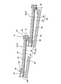
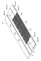
第1実施形態の屋根構造1は、図1で示されるように、建屋の屋根下地95の上に軒先金具2(図1では図示しない、図2等参照)を取り付け、さらに太陽電池モジュール3や、瓦部材4(屋根部材)を敷設して形成されるものである。また、必要部分には、破風板、水切り、化粧板等の屋根形成用部材(図示を省略する)を適宜取り付けている。   As shown in FIG. 1, the roof structure 1 of the first embodiment has an eaves fitting 2 (not shown in FIG. 1, see FIG. 2) attached on a roof base 95 of a building, and further includes a solar cell module 3 and The tile member 4 (roof member) is laid. Moreover, roof forming members (not shown) such as a windbreak plate, a drainer, and a decorative plate are appropriately attached to necessary portions.

軒先金具2は、図2で示されるように、一枚の金属板材を折り曲げ加工して形成されるものであり、平板状の取付板部10と、取付板部10の前端側(軒先側)から上方に突出する立板部11と、立板部11の上端から前方に向かって突出する屋根材掛止部12を備えている。   As shown in FIG. 2, the eaves-end fitting 2 is formed by bending a single metal plate, and includes a flat mounting plate portion 10 and a front end side (eave-end side) of the mounting plate portion 10. And a roof material latching portion 12 projecting forward from the upper end of the standing plate portion 11.

図2(a)で示されるように、取付板部10のうち、左右方向における一端側であり、後方側(棟側)に位置する部分には、左右方向における縁部分から中心側へ向かって延びる切欠部13が設けられている。この切欠部13は、取付板部10の一部を欠落させて形成される部分であり、平面視した形状が略四角形状となっている。より具体的には、この切欠部13は、取付板部10の後端からやや前方に位置する部分から、前後方向における中心よりもやや前方に位置する部分に至るまでの間で、左右方向における縁部分から中心側へ向かって延びている。   As shown in FIG. 2 (a), a portion of the mounting plate 10 that is on one end side in the left-right direction and is located on the rear side (ridge side) from the edge portion in the left-right direction toward the center side. An extending cutout 13 is provided. The cutout portion 13 is a portion formed by removing a part of the mounting plate portion 10 and has a substantially quadrangular shape in plan view. More specifically, the notch 13 is formed in the left-right direction from a portion located slightly forward from the rear end of the mounting plate portion 10 to a portion located slightly forward from the center in the front-rear direction. It extends toward the center side from the edge portion.

さらに、この取付板部10には、前後方向における中心近傍となる位置には、左右方向で間隔を空けて並列する2つの取付孔14が設けられている。すなわち、一方の取付孔14が左右方向における一端側から他端側に離れた位置に形成され、もう一方の取付孔14がさらに他端側に離れた位置であり、切欠部13と隣接する位置に形成されている。
それぞれの取付孔14は、取付板部10を厚さ方向(上下方向)に貫通する開口形状が円形の貫通孔となっている。
Further, the mounting plate portion 10 is provided with two mounting holes 14 that are arranged in parallel in the left-right direction at a position near the center in the front-rear direction. That is, one attachment hole 14 is formed at a position away from one end side to the other end side in the left-right direction, and the other attachment hole 14 is further away from the other end side, and is adjacent to the notch 13. Is formed.
Each attachment hole 14 is a through hole having a circular opening shape that penetrates the attachment plate portion 10 in the thickness direction (vertical direction).

立板部11は、取付板部10の前方側に位置する部分を上方に折り曲げて形成される立板状の部分であり、言い換えると、直立した姿勢をとる板状の部分となっている。より具体的には、図2(b)、図2(c)で示されるように、取付板部10の前方側に位置する部分のうち、2つの前方板片部15を除く部分を上方に折り曲げて形成している。
ここで、前方板片部15は、取付板部10と一体に形成され、平面視した形状が略四角形状となる平板状の部分である。この前方板片部15は、取付板部10の前方側で、左右方向で間隔を空けて並列した状態となっている。加えて、前方板片部15のそれぞれの上面は、取付板部10の上面と同一平面を形成しており、前方板片部15のそれぞれの下面は、取付板部10の下面と同一平面を形成している。すなわち、取付板部10と2つの前方板片部15とが一体となった板体が、取付板部10のうちで最も下方側に位置する平板状の部分を形成している。
The standing plate portion 11 is a standing plate-like portion formed by bending a portion located on the front side of the mounting plate portion 10 upward. In other words, the standing plate portion 11 is a plate-like portion taking an upright posture. More specifically, as shown in FIGS. 2 (b) and 2 (c), the portion excluding the two front plate pieces 15 in the portion located on the front side of the mounting plate portion 10 is directed upward. It is formed by bending.
Here, the front plate piece portion 15 is a flat plate portion that is formed integrally with the mounting plate portion 10 and has a substantially quadrangular shape in plan view. This front plate piece portion 15 is in a state of being arranged in parallel with a space in the left-right direction on the front side of the mounting plate portion 10. In addition, each upper surface of the front plate piece portion 15 forms the same plane as the upper surface of the mounting plate portion 10, and each lower surface of the front plate piece portion 15 is flush with the lower surface of the mounting plate portion 10. Forming. That is, the plate body in which the mounting plate portion 10 and the two front plate piece portions 15 are integrated forms a flat plate-like portion positioned on the lowermost side of the mounting plate portion 10.

立板部11のうち、前方板片部15の上方に位置する部分には、水抜孔16が形成されている。この水抜孔16は、立板部11を厚さ方向(前後方向)に貫通する開口形状が略四角形状の貫通孔となっている。より具体的には、この水抜孔16は、正面視した形状が略四角形状となる貫通孔であり、立板部11の下端から上下方向における中心よりやや上側に至るまでの間で延びる切欠き状の部分となっている。   A drain hole 16 is formed in a portion of the standing plate portion 11 located above the front plate piece portion 15. The drain hole 16 is a through hole having a substantially quadrangular opening shape that penetrates the upright plate portion 11 in the thickness direction (front-rear direction). More specifically, the drain hole 16 is a through-hole whose front view is a substantially rectangular shape, and is a notch extending from the lower end of the upright plate portion 11 to a position slightly above the center in the vertical direction. It has become a part of the shape.

屋根材掛止部12は、平板状の部分であり、その上面(又は下面)を含んで形成される平面と、取付板部10の上面(又は下面)を含んで形成される平面とが互いに平行となるように形成されている。さらに、屋根材掛止部12の下面と前方板片部15上面とが離間対向した状態となっており、これらが互いに平行な面となっている。
この屋根材掛止部12の下方であり、立板部11の前方側に位置する部分には、太陽電池モジュール3や瓦部材4の軒側端部を掛止するための掛止空間17が形成された状態となっている。つまり、この屋根材掛止部12は、太陽電池モジュール3や瓦部材4といった屋根下地95の上に敷設する部材を掛止するための部分となっている。
The roof material latching portion 12 is a flat portion, and a plane formed including the upper surface (or lower surface) thereof and a plane formed including the upper surface (or lower surface) of the mounting plate portion 10 are mutually connected. It is formed to be parallel. Furthermore, the lower surface of the roof material latching portion 12 and the upper surface of the front plate piece portion 15 are in a state of being opposed to each other, and these are parallel to each other.
A latching space 17 for latching the eaves side end of the solar cell module 3 or the tile member 4 is located below the roof material latching portion 12 and on the front side of the upright plate portion 11. It is in a formed state. That is, the roof material latching portion 12 is a portion for latching a member laid on the roof base 95 such as the solar cell module 3 or the tile member 4.

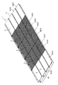
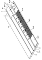
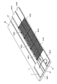
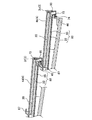
太陽電池モジュール3は、図3で示されるように、太陽電池パネル20をフレーム部材21に対して一体に取り付けることで形成されるものであり、長手方向(左右方向)における一端側に樋部22を備えた雨樋付きの太陽電池モジュール3となっている。すなわち、本実施形態のフレーム部材21は、樋部22が一体に形成された部材となっている。
この太陽電池モジュール3は、瓦や屋根板等の屋根部材の上に固定されるのではなく、これらの屋根部材に替わって屋根下地95(詳しくは、後述する)の上に直接取り付ける瓦一体型の太陽電池モジュール3となっている。
As shown in FIG. 3, the solar cell module 3 is formed by integrally attaching the solar cell panel 20 to the frame member 21, and has a flange 22 on one end side in the longitudinal direction (left-right direction). It becomes the solar cell module 3 with the rain gutter provided with. That is, the frame member 21 of the present embodiment is a member in which the flange portion 22 is integrally formed.
This solar cell module 3 is not fixed on a roof member such as a tile or a roof plate, but is a tile-integrated type that is directly mounted on a roof base 95 (details will be described later) instead of these roof members. It becomes the solar cell module 3.

太陽電池パネル20は、光エネルギーを電気エネルギーに変換する光電変換装置であり、面状に広がりを持った薄板状の装置となっている。すなわち、太陽電池パネル20は、平面視した形状が略横長長方形状の板体となっている。
この太陽電池パネル20には、特に限定されるものではないが、所謂結晶型太陽電池パネルと称されるものや、薄膜型太陽電池パネルと称されるものを好適に採用することができる。なお、結晶型太陽電池パネルとは、ガラス板と封止部材との間に複数の太陽電池を配し、この太陽電池間を配線部材によって電気的に接続したものである。対して、薄膜型太陽電池パネルとは、ガラス板に導電膜や半導体膜を積層し、これに複数の溝を設けて所定数の単体電池(太陽電池)を形成し、各太陽電池を電気的に接続したものである。
The solar cell panel 20 is a photoelectric conversion device that converts light energy into electrical energy, and is a thin plate-like device having a planar shape. That is, the solar cell panel 20 is a plate body having a substantially horizontally long rectangular shape in plan view.
Although it does not specifically limit to this solar cell panel 20, What is called what is called a crystal type solar cell panel and what is called a thin film type solar cell panel can be employ | adopted suitably. The crystal solar cell panel is a solar cell panel in which a plurality of solar cells are arranged between a glass plate and a sealing member, and the solar cells are electrically connected by a wiring member. On the other hand, a thin-film solar cell panel is formed by laminating a conductive film or a semiconductor film on a glass plate and providing a plurality of grooves in the glass plate to form a predetermined number of unit cells (solar cells). Is connected to.

この太陽電池パネル20の裏面側には、図4で示されるように、端子ボックス23が一体に取り付けられており、端子ボックス23からは、二本のケーブルが延設されている。このケーブルは、太陽電池パネル20で発電した電力を伝送するための出力ケーブルであり、他の太陽電池モジュール3や、外部負荷に対して接続可能なものとなっている。
この端子ボックス23は、太陽電池パネル20をフレーム部材21に装着した状態において、フレーム部材21の本体板部30に形成されたボックス挿通孔45(詳しくは後述する)に挿通され、太陽電池モジュール3の裏面側に露出した状態となっている。
As shown in FIG. 4, a terminal box 23 is integrally attached to the back surface side of the solar cell panel 20, and two cables are extended from the terminal box 23. This cable is an output cable for transmitting the electric power generated by the solar cell panel 20, and can be connected to another solar cell module 3 and an external load.
The terminal box 23 is inserted into a box insertion hole 45 (described later in detail) formed in the main body plate portion 30 of the frame member 21 in a state where the solar cell panel 20 is mounted on the frame member 21, and the solar cell module 3. It is in the state exposed to the back side.

フレーム部材21は、図4、図5で示されるように、本体板部30と、フロントカバー31と、発泡断熱材32と、押さえ板部材33(図3、図5参照)とを備えている。   As shown in FIGS. 4 and 5, the frame member 21 includes a main body plate portion 30, a front cover 31, a foam heat insulating material 32, and a pressing plate member 33 (see FIGS. 3 and 5). .

本体板部30は、図4で示されるように、大別して、太陽電池パネル20を取り付けるための部分であるモジュール形成部30aと、樋部22とを備えた構造となっている。
この本体板部30のモジュール形成部30aは、図5で示されるように、太陽電池パネル20を載置する載置板部38と、載置板部38の前端側(軒側)を下方に折り曲げて形成される立板状のカバー取付部39と、載置板部38の後端側(棟側)を上方に折り曲げて形成される立板状の連結板部40と、連結板部40の後端から後方に突出する平板状の押さえ板取付部41と、押さえ板取付部41の後端側と連続する棟側辺部42を備えた構造となっている。
As shown in FIG. 4, the main body plate portion 30 is roughly divided into a structure including a module forming portion 30 a that is a portion for attaching the solar cell panel 20 and a flange portion 22.
As shown in FIG. 5, the module forming portion 30 a of the main body plate portion 30 has a placement plate portion 38 on which the solar cell panel 20 is placed and a front end side (eave side) of the placement plate portion 38 downward. A standing plate-like cover mounting portion 39 formed by bending, a standing plate-like connecting plate portion 40 formed by bending the rear end side (ridge side) of the mounting plate portion 38 upward, and a connecting plate portion 40. It has a structure including a flat pressing plate mounting portion 41 protruding rearward from the rear end and a ridge side portion 42 continuous with the rear end side of the pressing plate mounting portion 41.

ここで、図4で示されるように、載置板部38の中心部分、すなわち、載置板部38の前後方向における中心近傍であり、左右方向における中心近傍となる部分には、端子ボックス23を挿通するためのボックス挿通孔45が形成されている。
このボックス挿通孔45は、本体板部30を厚さ方向(上下方向)に貫通する貫通孔であり、平面視した形状が略四角形状となる孔となっている。また、このボックス挿通孔45は、その左右方向の長さが端子ボックス23の左右方向の長さよりも長く、前後方向の長さが端子ボックス23の前後方向の長さよりも長くなっている。すなわち、ボックス挿通孔45の開口面積は、端子ボックス23の平面視面積(上下方向に投影した際の面)よりも大きくなっている。
Here, as shown in FIG. 4, a terminal box 23 is provided in the central portion of the mounting plate portion 38, that is, in the vicinity of the center in the front-rear direction of the mounting plate portion 38 and in the vicinity of the center in the left-right direction. A box insertion hole 45 is formed for inserting the.
The box insertion hole 45 is a through hole that penetrates the main body plate portion 30 in the thickness direction (vertical direction), and is a hole whose shape in plan view is a substantially rectangular shape. Further, the length of the box insertion hole 45 in the left-right direction is longer than the length in the left-right direction of the terminal box 23, and the length in the front-rear direction is longer than the length in the front-rear direction of the terminal box 23. That is, the opening area of the box insertion hole 45 is larger than the planar view area of the terminal box 23 (surface when projected in the vertical direction).

また、棟側辺部42は、図5で示されるように、押さえ板取付部41の後方に位置する部分を折り曲げることで形成される部分であり、押さえ板取付部41の後端から上方に突出する段差形成部42aと、段差形成部42aの後端から後方に突出する平板状の棟側端形成部42bとを備えた構造となっている。   Further, as shown in FIG. 5, the ridge side portion 42 is a portion formed by bending a portion located behind the pressing plate mounting portion 41, and upward from the rear end of the pressing plate mounting portion 41. The structure includes a protruding step forming portion 42a and a flat ridge side end forming portion 42b protruding backward from the rear end of the step forming portion 42a.

樋部22は、図3、図4で示されるように、本体板部30の一部であり、本体板部30の長手方向(左右方向)における一端側を折り曲げ加工して形成される部分である。
より具体的には、樋部22は、図3で示されるように、本体板部30の長手方向における一端側に位置する縁部分近傍を折り曲げ加工して形成されるものであり、モジュール形成部30aの長手方向における一端側に隣接するように形成されている。
As shown in FIGS. 3 and 4, the flange portion 22 is a part of the main body plate portion 30, and is a portion formed by bending one end side in the longitudinal direction (left-right direction) of the main body plate portion 30. is there.
More specifically, as shown in FIG. 3, the flange portion 22 is formed by bending the vicinity of an edge portion located on one end side in the longitudinal direction of the main body plate portion 30. It is formed so as to be adjacent to one end side in the longitudinal direction of 30a.

この樋部22は、平板状の樋底板部22aと、樋底板部22aの後方部分を上方に折り曲げて形成される樋後方壁部22bと、樋底板部22a左右方向における端部のうちで外側に位置する端部から上方に突出する外側樋側壁部22c(樋側壁部)と、樋底板部22a左右方向における端部のうちで内側に位置する端部から上方に突出する内側樋側壁部22d(樋側壁部)とを備えた構造となっている。そして、外側樋側壁部22cと内側樋側壁部22dとが、左右方向で離間対向した状態となっている。   The flange portion 22 includes a flat bottom plate portion 22a, a reverse wall portion 22b formed by bending a rear portion of the reverse plate portion 22a upward, and an end portion in the left-right direction of the reverse plate portion 22a. Outer side wall side part 22c (upper side wall part) that protrudes upward from the end part located on the inner side, and inner side wall side wall part 22d that protrudes upward from the end part located on the inner side among the end parts in the left and right direction of the bottom side plate part 22a It is a structure provided with (a heel side wall part). And the outer side wall side wall part 22c and the inner side wall side wall part 22d are in a state of facing each other in the left-right direction.

ここで、樋後方壁部22bの左右方向における両端部のそれぞれと、外側樋側壁部22cの後端部分、内側樋側壁部22dの後端部分は連続した状態となっている。そして、樋底板部22aの上方に形成される空間は、樋後方壁部22b、外側樋側壁部22c、内側樋側壁部22dによって3方を囲まれた状態となっている。すなわち、樋部22は、上方部分と、前方部分(軒側部分)が開放された略有底箱状の部分となっている。そして、樋底板部22aの上方に形成される空間であり、樋後方壁部22b、外側樋側壁部22c、内側樋側壁部22dによって3方を囲まれた空間である樋内溝状空間24が、雨水が流れるための流路として機能する。   Here, each of both ends in the left-right direction of the heel rear wall portion 22b, the rear end portion of the outer heel side wall portion 22c, and the rear end portion of the inner heel side wall portion 22d are in a continuous state. The space formed above the bottom plate portion 22a is surrounded by three sides by the rear wall portion 22b, the outer side wall portion 22c, and the inner side wall portion 22d. That is, the collar part 22 is a substantially bottomed box-like part in which an upper part and a front part (eave side part) are opened. The inner groove-like space 24, which is a space formed above the bottom plate 22a, is a space surrounded by the rear wall 22b, the outer side wall 22c, and the inner side wall 22d. Functions as a flow path for rainwater to flow through.

つまり、この樋内溝状空間24は、前後方向(屋根上設置時における軒棟方向)に延びた、溝状の空間となっている。すなわち、樋部22の内側に形成され、棟側(後側)から軒側(前側)へ雨水を流すための空間となっている。   That is, the in-gutter groove-like space 24 is a groove-like space extending in the front-rear direction (in the direction of the eaves building when installed on the roof). That is, it is formed inside the collar part 22 and is a space for flowing rainwater from the ridge side (rear side) to the eaves side (front side).

また、樋底板部22aの前端部分には、前方傾斜部46が形成されている。前方傾斜部46は、樋底板部22aの前端部分を下方側に向かって僅かに曲げることで形成されており、その上面が、前方側に向かって下り勾配となるように緩やかに傾斜した傾斜面となっている。
より具体的には、この前方傾斜部46は、樋底板部22aのうち、樋後方壁部22b及び外側樋側壁部22cの前端よりも前方に位置する部分を折り曲げ加工して形成されるものであり、言い換えると、樋底板部22aの前端部分は、樋後方壁部22b、外側樋側壁部22cの前端よりも前方に位置した状態となっている。
Further, a front inclined portion 46 is formed at the front end portion of the bottom plate portion 22a. The front inclined portion 46 is formed by slightly bending the front end portion of the bottom plate 22a toward the lower side, and the inclined surface is gently inclined so that the upper surface thereof becomes a downward gradient toward the front side. It has become.
More specifically, the front inclined portion 46 is formed by bending a portion of the heel bottom plate portion 22a located forward of the front ends of the heel rear wall portion 22b and the outer heel side wall portion 22c. Yes, in other words, the front end portion of the heel bottom plate portion 22a is positioned in front of the front ends of the heel rear wall portion 22b and the outer heel side wall portion 22c.

フロントカバー31は、図5で示されるように、立板状の前方保護板部48と、前方保護板部48の上端を後方に折り曲げて形成される平板状の上端平板部49と、前方保護板部48の下端を後方に折り曲げて形成される平板状のモジュール軒側掛止部50とを備えた構造となっている。
すなわち、このフロントカバー31は、図3、図5で示されるように、断面形状が略「コ」字状となり、左右方向に延びる長尺体となっている。
As shown in FIG. 5, the front cover 31 includes an upright plate-shaped front protective plate portion 48, a flat upper end flat plate portion 49 formed by bending the upper end of the front protective plate portion 48 rearward, and a front protection. It has a structure provided with a flat module eaves side latching portion 50 formed by bending the lower end of the plate portion 48 backward.
That is, as shown in FIGS. 3 and 5, the front cover 31 has a substantially “U” cross-sectional shape and is a long body extending in the left-right direction.

このフロントカバー31は、図5で示されるように、前方保護板部48とカバー取付部39と前後方向で重ね合わせた状態とし、これらにネジ、釘等の締結要素を挿通することで、本体板部30に対して一体に取り付けられるものである。言い換えると、前方保護板部48の背面(後端面)と、カバー取付部39の前面(前端面)を接触させ、締結要素を挿通することで、本体板部30に対して固定されるものとなっている。
なお、本実施形態における締結要素とは、ビス、ネジ(木ネジを含む)、釘等の上位概念とする。
As shown in FIG. 5, the front cover 31 is in a state where the front protection plate portion 48 and the cover mounting portion 39 are overlapped in the front-rear direction, and a fastening element such as a screw or a nail is inserted through these, It is attached to the plate part 30 integrally. In other words, the back surface (rear end surface) of the front protection plate portion 48 and the front surface (front end surface) of the cover mounting portion 39 are brought into contact with each other and are fixed to the main body plate portion 30 by inserting the fastening element. It has become.
The fastening elements in this embodiment are superordinate concepts such as screws, screws (including wood screws), nails and the like.

ここで、フレーム部材21において、フロントカバー31が本体板部30に取り付けられた状態では、上端平板部49と、前方保護板部48と、載置板部38によって囲まれた部分に、太陽電池パネル20の軒側端部を保持するための軒側保持凹部55が形成されることとなる。
この軒側保持凹部55は、前方に向かって窪む凹部となっている。すなわち、軒側保持凹部55は、上下方向で離間対向とする上端平板部49と、載置板部38の軒側端部との間であって、前方保護板部48の後方に位置する空間となっている。
Here, in the frame member 21, in a state where the front cover 31 is attached to the main body plate portion 30, the solar cell is placed in a portion surrounded by the upper end flat plate portion 49, the front protection plate portion 48, and the mounting plate portion 38. The eaves-side holding recess 55 for holding the eaves-side end portion of the panel 20 is formed.
The eaves side holding recess 55 is a recess that is recessed forward. In other words, the eaves-side holding recess 55 is a space located between the upper end flat plate portion 49 that is spaced apart in the vertical direction and the eaves-side end portion of the placement plate portion 38 and behind the front protection plate portion 48. It has become.

発泡断熱材32は、図4で示されるように、太陽電池モジュール3の強度や断熱性を確保するために本体板部30の裏面に取り付けられる発泡樹脂製の部材である。
この発泡断熱材32は、本体板部30の長手方向(左右方向)に沿って延びる断熱材本体部32aと、断熱材本体部32aの長手方向の両端部分からそれぞれ前方へ突出する前方平板部32bとを備えており、これらが一体になって形成されている。言い換えると、発泡断熱材32は、平面視した形状が略「コ」字状となるように延びる部材となっている。
As shown in FIG. 4, the foam heat insulating material 32 is a member made of foamed resin that is attached to the back surface of the main body plate portion 30 in order to ensure the strength and heat insulation of the solar cell module 3.
The foamed heat insulating material 32 includes a heat insulating material main body 32a extending along the longitudinal direction (left-right direction) of the main body plate portion 30, and a front flat plate portion 32b protruding forward from both end portions of the heat insulating material main body 32a in the longitudinal direction. And these are formed integrally. In other words, the foam heat insulating material 32 is a member that extends so that the shape in plan view is a substantially “U” shape.

ここで、断熱材本体部32aは、前方平板部32bよりも厚くなっている。そして、断熱材本体部32aと前方平板部32bが連続する部分には、丸みを帯びた湾曲面が形成されており、この湾曲面が、太陽電池モジュール3の表面側後方(図4における下方後側)に向かって凹となる凹曲面であって、後方に向かうにつれて高さが高くなる面となっている。   Here, the heat insulating main body 32a is thicker than the front flat plate 32b. And the rounded curved surface is formed in the part which the heat insulating main-body part 32a and the front flat plate part 32b continue, and this curved surface is the surface side back of the solar cell module 3 (lower back in FIG. 4). It is a concave curved surface that becomes concave toward the side), and is a surface that increases in height toward the rear.

また、断熱材本体部32aには、前後方向に延びるケーブル配置溝56が複数(本実施形態では3つ)形成されている。このケーブル配置溝56は、断熱材本体部32aの前端から後端まで延びるものであり、周囲の部分よりも厚さの薄くなった部分でもある。
より具体的には、3つのケーブル配置溝56が左右方向で間隔を空けて並列しており、断熱材本体部32aの左右方向における中心近傍に1つのケーブル配置溝56が形成され、このケーブル配置溝56よりも左右方向における片側端部側に離れた位置に2つ目のケーブル配置溝56が形成され、左右方向における他方端部側に離れた位置に3つ目のケーブル配置溝56が形成されている。
In addition, a plurality (three in this embodiment) of cable arrangement grooves 56 extending in the front-rear direction are formed in the heat insulating material main body 32a. The cable arrangement groove 56 extends from the front end to the rear end of the heat insulating material main body 32a, and is also a portion that is thinner than the surrounding portion.
More specifically, three cable arrangement grooves 56 are arranged in parallel in the left-right direction, and one cable arrangement groove 56 is formed near the center in the left-right direction of the heat insulating body main body 32a. A second cable arrangement groove 56 is formed at a position away from one end in the left-right direction from the groove 56, and a third cable arrangement groove 56 is formed at a position away from the other end in the left-right direction. Has been.

さらに、断熱材本体部32aには、左右方向に直線状に延びる取付用溝57が形成されている。この取付用溝57は、断熱材本体部32aの左右方向における一端から他端まで延びており、ケーブル配置溝56が形成されている部分と、ケーブル配置溝56が形成されていない部分を跨って延びている。そして、それぞれの部分において、周囲の部分よりも厚さの薄くなった部分となっている。   Furthermore, a mounting groove 57 extending linearly in the left-right direction is formed in the heat insulating material main body 32a. The mounting groove 57 extends from one end to the other end in the left-right direction of the heat insulating material main body 32a, and straddles a portion where the cable arrangement groove 56 is formed and a portion where the cable arrangement groove 56 is not formed. It extends. In each portion, the portion is thinner than the surrounding portion.

ところで、この発泡断熱材32は、図4で示されるように、その全体が樋部22よりの位置に配されている。すなわち、本体板部30の左右方向の端部のうち、樋部22側に位置する端部から、他方側の端部よりやや中心よりの位置までの間に配されている。
このため、本体板部30のうち、左右方向における端部であり、樋部22よりの端部と対となる端部の周辺には、前端から後端までの間に端子ボックス23及び発泡断熱材32を含む他部材が取り付けられておらず、本体板部30のみが位置する樋部配置領域58が形成されている。
By the way, as shown in FIG. 4, the whole foam heat insulating material 32 is arranged at a position from the flange portion 22. That is, among the end portions in the left-right direction of the main body plate portion 30, the main body plate portion 30 is disposed between the end portion located on the flange portion 22 side and the position slightly closer to the center than the other end portion.
For this reason, it is an edge part in the left-right direction among the main body board parts 30, and the terminal box 23 and foam heat insulation between the front end and the rear end in the circumference | surroundings of the edge part which becomes a pair with the edge part from the collar part 22. Other members including the material 32 are not attached, and a collar arrangement region 58 in which only the main body plate portion 30 is located is formed.

この樋部配置領域58は、左右方向(幅方向)の長さが樋部22の左右方向(幅方向)の長さよりもやや長くなっている。具体的には、樋部22に樋延長部材65を装着して形成される雨水の流通路(詳しくは後述する)の長さよりもやや長くなっている。   The length of the collar part arrangement region 58 is slightly longer in the left-right direction (width direction) than the length of the collar part 22 in the left-right direction (width direction). Specifically, it is slightly longer than the length of a rainwater flow path (details will be described later) formed by attaching the eaves extension member 65 to the eaves portion 22.

押さえ板部材33は、図3、図5で示されるように、左右方向に延びる平板状の部分であり、長尺状に延びた部材となっている。そして、この押さえ板部材33には、モジュール棟側掛止部59と、取付用孔(図示しない)とが形成されている。なお、この取付用孔は、押さえ板部材33を上下方向に貫通する貫通孔であり、本実実施形態では、複数の取付用孔が左右方向で間隔を空けて配された状態となっている。   As shown in FIGS. 3 and 5, the pressing plate member 33 is a flat plate portion extending in the left-right direction, and is a member extending in a long shape. The pressing plate member 33 is formed with a module ridge side latching portion 59 and a mounting hole (not shown). This mounting hole is a through-hole penetrating the pressing plate member 33 in the vertical direction. In the present embodiment, a plurality of mounting holes are arranged at intervals in the left-right direction. .

モジュール棟側掛止部59は、押さえ板部材33の一部を切り起こして形成される部分であり、図5で示されるように、上方に向かって突出する立板状の支持板部59aと、支持板部59aの上端から前方に突出する掛止板部59bとを備えている。すなわち、モジュール棟側掛止部59は、支持板部59a、掛止板部59bが一体となって形成される部分であり、断面形状が略「L」字状で左右方向に延びる部分となっている。
本実施形態の押さえ板部材33では、このモジュール棟側掛止部59が複数設けられており、左右方向で間隔を空けて配された状態となっている。
The module ridge-side latching portion 59 is a portion formed by cutting and raising a part of the pressing plate member 33, and as shown in FIG. 5, a standing plate-like support plate portion 59a protruding upward And a latch plate portion 59b protruding forward from the upper end of the support plate portion 59a. That is, the module building side latching portion 59 is a portion where the support plate portion 59a and the latching plate portion 59b are integrally formed, and the cross-sectional shape is a substantially “L” shape and is a portion extending in the left-right direction. ing.
In the pressing plate member 33 of the present embodiment, a plurality of the module ridge side latching portions 59 are provided and are arranged at intervals in the left-right direction.

この押さえ板部材33は、図5で示されるように、押さえ板部材33の後側部分を、本体板部30の押さえ板取付部41に上下方向で重ねた状態とし、これらに締結要素を挿通することで、一体に固定する。
押さえ板部材33が本体板部30に取り付けられると、押さえ板部材33の前側部分と、連結板部40と、載置板部38によって囲まれた部分に、太陽電池パネル20の棟側端部を保持するための棟側保持凹部60が形成されることとなる。
この棟側保持凹部60は、前端(図5では右端)に内外を連通する開口部分を有し、後方(図5では左側)に向かって窪む凹部となっている。すなわち、棟側保持凹部60は、上下方向で離間対向とする押さえ板部材33と、載置板部38の棟側端部との間であって、連結板部40の前方に位置する空間となっている。付言すると、図5では、この空間に、ガスケット部材を取り付けた太陽電池パネル20の棟側端部を配した状態を示している。
As shown in FIG. 5, the pressing plate member 33 is configured such that the rear side portion of the pressing plate member 33 is overlapped with the pressing plate mounting portion 41 of the main body plate portion 30 in the vertical direction, and a fastening element is inserted therethrough. To fix it together.
When the pressing plate member 33 is attached to the main body plate portion 30, the ridge side end portion of the solar cell panel 20 is surrounded by the front portion of the pressing plate member 33, the connecting plate portion 40, and the mounting plate portion 38. A ridge-side holding concave portion 60 for holding the wing is formed.
The ridge-side holding recess 60 has a front end (right end in FIG. 5) having an opening that communicates inside and outside, and is a recess that is recessed toward the rear (left side in FIG. 5). That is, the ridge-side holding recess 60 is a space between the pressing plate member 33 that is spaced apart in the vertical direction and the ridge-side end portion of the placement plate portion 38 and located in front of the connecting plate portion 40. It has become. If it adds, in FIG. 5, the state which has arrange | positioned the ridge side edge part of the solar cell panel 20 which attached the gasket member in this space is shown.

次に、太陽電池パネル20をフレーム部材21に取り付ける際の取り付け手順、すなわち、太陽電池モジュール3の組み立て手順について説明する。
太陽電池モジュール3を組み立てる際には、まず、押さえ板部材33を取り外した状態のフレーム部材21に対して、太陽電池パネル20を載置板部38の上に載置する。
このとき、太陽電池パネル20の軒側端部を軒側保持凹部55の内側に挿入し、太陽電池パネル20の軒側端部が軒側保持凹部55によって保持された状態とする。なお、必要に応じて太陽電池パネル20と軒側保持凹部55の間にガスケット部材を介在させる。
さらにこのとき、太陽電池パネル20の裏面側に位置する端子ボックス23と、この端子ボックス23から延設されるケーブルとを、載置板部38に形成されたボックス挿通孔45に上方から挿入する(図4等参照)。このことにより、図4で示されるように、太陽電池モジュール3を下方側からみたとき、端子ボックス23とケーブルが外部に露出した状態となる。言い換えると、端子ボックス23の大部分とケーブルとが、ボックス挿通孔45の下方側(図4では上方側)の開口よりもさらに下方側(図4では上方)に位置した状態となる。
Next, an attachment procedure when attaching the solar cell panel 20 to the frame member 21, that is, an assembly procedure of the solar cell module 3 will be described.
When assembling the solar cell module 3, first, the solar cell panel 20 is placed on the placement plate portion 38 with respect to the frame member 21 with the pressing plate member 33 removed.
At this time, the eaves side end of the solar cell panel 20 is inserted inside the eaves side holding recess 55, and the eaves side end of the solar cell panel 20 is held by the eaves side holding recess 55. In addition, a gasket member is interposed between the solar cell panel 20 and the eaves side holding recessed part 55 as needed.
Further, at this time, the terminal box 23 positioned on the back side of the solar cell panel 20 and the cable extending from the terminal box 23 are inserted into the box insertion hole 45 formed in the mounting plate portion 38 from above. (See FIG. 4 etc.). As a result, as shown in FIG. 4, when the solar cell module 3 is viewed from below, the terminal box 23 and the cable are exposed to the outside. In other words, most of the terminal box 23 and the cable are located further below (upward in FIG. 4) than the opening on the lower side (upper in FIG. 4) of the box insertion hole 45.

この状態において、押さえ板部材33を本体板部30(押さえ板取付部41)に対して固定する。すなわち、押さえ板部材33と押さえ板取付部41を上下方向で重ねた状態とし、押さえ板部材33の取付用孔(図示しない)が位置する部分に締結要素を挿通することで、一体に固定する。このことにより、上記したように棟側保持凹部60が形成され、太陽電池パネル20の棟側端部が棟側保持凹部60によって保持された状態となる。なお、このときもまた、必要に応じて太陽電池パネル20と棟側保持凹部60の間にガスケット部材を介在させる。
すなわち、フレーム部材21の軒側保持凹部55、棟側保持凹部60によって太陽電池パネル20の軒側端部、棟側端部のそれぞれが保持された状態となり、フレーム部材21に太陽電池パネル20が一体に取り付けられた状態となる。
In this state, the pressing plate member 33 is fixed to the main body plate portion 30 (the pressing plate mounting portion 41). That is, the pressing plate member 33 and the pressing plate mounting portion 41 are overlapped in the vertical direction, and the fastening element is inserted into a portion where the mounting hole (not shown) of the pressing plate member 33 is located, so that they are fixed integrally. . As a result, the ridge-side holding recess 60 is formed as described above, and the ridge-side end portion of the solar cell panel 20 is held by the ridge-side holding recess 60. Also at this time, a gasket member is interposed between the solar cell panel 20 and the ridge-side holding recess 60 as necessary.
That is, the eaves side holding recess 55 and the ridge side holding recess 60 of the frame member 21 hold the eaves side end and the ridge side end of the solar cell panel 20, and the solar cell panel 20 is attached to the frame member 21. It is in a state of being attached integrally.

このように組み立てられた太陽電池モジュール3では、図3、図5で示されるように、太陽電池パネル20の軒端側の一部の上方に、押さえ板部材33及びモジュール棟側掛止部59が位置した状態となる。言い換えると、太陽電池モジュール3の棟端よりも所定距離れた位置に、モジュール棟側掛止部59が位置した状態となる。そして、太陽電池パネル20の軒端側の一部と棟端側の一部を除く大部分が受光面として、外部に露出した状態となる。
言い換えると、太陽電池パネル20の受光面の棟側に隣接する位置に、押さえ板部材33及びモジュール棟側掛止部59が位置し、軒側に隣接する位置にフロントカバー31が位置した状態となる。
In the solar cell module 3 assembled in this way, as shown in FIG. 3 and FIG. 5, the pressing plate member 33 and the module building side latching portion 59 are provided above a part of the eaves end side of the solar cell panel 20. It will be in the position. In other words, the module building side latching portion 59 is located at a position a predetermined distance from the building edge of the solar cell module 3. And most of the solar cell panel 20 excluding a part on the eaves end side and a part on the ridge end side is exposed to the outside as a light receiving surface.
In other words, the pressing plate member 33 and the module building side latching portion 59 are located at a position adjacent to the ridge side of the light receiving surface of the solar cell panel 20, and the front cover 31 is located at a position adjacent to the eave side. Become.

ここで、図3で示されるように、押さえ板部材33は、太陽電池パネル20の棟側にのみ位置し、樋部22の棟側や上方には位置しない状態となっている。同様に、フロントカバー31は、太陽電池パネル20の軒側(前方)にのみ位置し、樋部22の軒側(前方)には位置しない状態となっている。すなわち、本実施形態の太陽電池モジュール3は、平面視において軒側から順にフロントカバー31、太陽電池パネル20、押さえ板部材33、棟側辺部42が位置する太陽電池モジュール本体部63と、この太陽電池モジュール本体部63と隣接する位置に形成される樋部22とに区分される構造となっており、樋部22の前方(軒側)、後方(棟側)、上方、下方には、太陽電池モジュール本体部63が位置しない状態となっている。すなわち、本実施形態の太陽電池モジュール3は、太陽電池モジュール本体部63が形成される本体側領域と、樋部22が形成される樋形成領域に区画されているといえる。   Here, as shown in FIG. 3, the pressing plate member 33 is located only on the ridge side of the solar cell panel 20 and is not located on the ridge side or above the collar portion 22. Similarly, the front cover 31 is located only on the eaves side (front) of the solar cell panel 20 and is not located on the eaves side (front) of the collar portion 22. That is, the solar cell module 3 of the present embodiment includes, in plan view, the solar cell module main body 63 in which the front cover 31, the solar cell panel 20, the pressing plate member 33, and the ridge side portion 42 are located in this order from the eaves side. It is structured to be divided into the solar cell module main body 63 and the flange portion 22 formed at an adjacent position, and the front (eave side), rear (ridge side), upper, and lower sides of the flange portion 22 The solar cell module main body 63 is not positioned. That is, it can be said that the solar cell module 3 of the present embodiment is divided into a main body side region where the solar cell module main body portion 63 is formed and a ridge forming region where the flange portion 22 is formed.

そして、樋部22の前端(軒側端部)は、太陽電池モジュール本体部63の前端(軒側端部)よりも後方(棟側)に位置しており、樋部22の後端(棟側端部)は、太陽電池モジュール本体部63の後端(棟側端部)の側方に位置している。より具体的には、樋部22の前端は、フロントカバー31におけるモジュール軒側掛止部50の後端よりも後方に位置しており、樋部22と太陽電池モジュール本体部63のそれぞれの後端(棟側端部)は、その前後方向(軒棟方向)における位置が略同一となっている。このことから、樋部22の前後方向(軒棟方向)における長さは、太陽電池モジュール本体部63の前後方向(軒棟方向)における長さよりも短くなっており、樋部22は、太陽電池モジュール本体部63の後端(棟側端部)の側方から、太陽電池モジュール本体部63の前端(軒側端部)よりもやや後方(棟側)となる位置の側方までの間で延びる部分となっている。   And the front end (eave side end part) of the collar part 22 is located in the back (building side) rather than the front end (eave side edge part) of the solar cell module main-body part 63, and the rear end (building side) of the collar part 22 The side end portion is located on the side of the rear end (ridge side end) of the solar cell module main body 63. More specifically, the front end of the flange portion 22 is located behind the rear end of the module eaves side latching portion 50 in the front cover 31, and the rear end of each of the flange portion 22 and the solar cell module main body portion 63. The end (ridge-side end) has substantially the same position in the front-rear direction (eave building direction). From this, the length in the front-rear direction (eave building direction) of the collar part 22 is shorter than the length in the front-rear direction (eave building direction) of the solar cell module main body 63, and the collar part 22 is a solar cell. From the side of the rear end (ridge side end) of the module main body 63 to the side of the position slightly behind (building side) the front end (eave side end) of the solar cell module main body 63. It is an extended part.

また、樋部22の上端は、太陽電池モジュール本体部63の上端よりも下方に位置しており、より詳細には、この樋部22の上端は、太陽電池パネル20の上面(受光面)よりも下方側に位置している。そして、樋部22の下端は、フロントカバー31の下端よりも上方であり、太陽電池パネル20の下面よりも下方側に位置している。
つまり、樋部22は、太陽電池モジュール本体部63の上下方向における中心近傍の側方に位置する部分となっている。
Moreover, the upper end of the collar part 22 is located below the upper end of the solar cell module main body part 63. More specifically, the upper end of the collar part 22 is from the upper surface (light-receiving surface) of the solar cell panel 20. Is also located on the lower side. And the lower end of the collar part 22 is located above the lower end of the front cover 31, and is located below the lower surface of the solar cell panel 20.
That is, the flange portion 22 is a portion located on the side near the center in the vertical direction of the solar cell module main body portion 63.

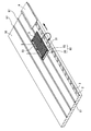
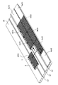
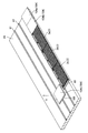
また、本実施形態の太陽電池モジュール3では、図6で示されるように、樋部22に対して樋延長部材65を一体に取り付けることにより、雨水の流通路の長さを延長することが可能となっている。すなわち、樋部22と樋延長部材65によって雨水の流通路を形成することで、樋部22のみによって雨水の流通路を形成した場合に比べ、前後方向(軒棟方向)に長い雨水の流通路を形成可能となっている。
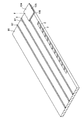
   Moreover, in the solar cell module 3 of this embodiment, as shown in FIG. 6, it is possible to extend the length of the rainwater flow path by integrally attaching the eaves extension member 65 to the eaves portion 22. It has become. In other words, the rainwater flow path is formed by the eaves part 22 and the eaves extension member 65, so that the rainwater flow path is longer in the front-rear direction (eave building direction) than when the rainwater flow path is formed only by the eaves part 22. Can be formed.

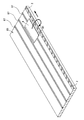
樋延長部材65は、図7で示されるように、前後方向(軒棟方向)に延びる平板状の底板形成部70(延長側底板部)と、底板形成部70の短手方向の一端側に位置する内側側壁部71(延長側側壁部)と、他端側に位置する外側側壁部72(延長側側壁部)とを備えた構造となっている。   As shown in FIG. 7, the eaves extending member 65 is formed on a flat bottom plate forming portion 70 (extension side bottom plate portion) extending in the front-rear direction (eave building direction) and one end side in the short direction of the bottom plate forming portion 70. The inner side wall portion 71 (extended side wall portion) located and the outer side wall portion 72 (extended side wall portion) located on the other end side are provided.

底板形成部70の前端(軒側端部)には、底板形成部70の前端側を下方側に折り曲げた後、さらにその下端側を後方へ折り曲げて形成される延長樋掛止部73(掛止部)が形成されている。言い換えると、延長樋掛止部73は、底板形成部70の前端から下方側へと延び、その後に後方側へと延びた部分となっている。
すなわち、延長樋掛止部73は、底板形成部70の前端側から下方に延びる立板状の接続板部73aと、接続板部73aの下端から後方へ延びる平板状の掛止板体部73bとを備えている。言い換えると、この延長樋掛止部73は、側面視形状が略「L」字状となるように曲成した鉤状の部分であるともいえる。
At the front end (eave side end) of the bottom plate forming portion 70, an extension hook retaining portion 73 (hanging) formed by bending the front end side of the bottom plate forming portion 70 downward and further bending the lower end side rearward. Stop) is formed. In other words, the extended hook latching portion 73 is a portion that extends downward from the front end of the bottom plate forming portion 70 and then extends to the rear side.
That is, the extended hook latching portion 73 includes a vertical plate-like connecting plate portion 73a extending downward from the front end side of the bottom plate forming portion 70 and a flat plate-like latching plate body portion 73b extending rearward from the lower end of the connecting plate portion 73a. And. In other words, it can be said that the extended hook locking portion 73 is a hook-like portion that is bent so that the side view shape is substantially “L” shape.

内側側壁部71は、底板形成部70の短手方向の一端を上方に折り曲げて形成されており、底板形成部70から上方に突出する立板状の部分である。
この内側側壁部71は、樋延長部材65の短手方向にそれぞれ位置して離間対向する2つの側壁部分の一方を形成する部分であり、図6で示されるように、樋部22への装着時に太陽電池モジュール本体部63側に位置する側壁部分を形成している。すなわち、内側側壁部71は、底板形成部70の短手方向における内側端部から上方に突出する部分となっている。
The inner side wall portion 71 is formed by bending one end of the bottom plate forming portion 70 in the short direction upward, and is a vertical plate-like portion protruding upward from the bottom plate forming portion 70.
The inner side wall portion 71 is a portion that forms one of two side wall portions that are positioned in the lateral direction of the heel extension member 65 and are opposed to each other, and is attached to the heel portion 22 as shown in FIG. Sometimes a side wall portion located on the solar cell module main body 63 side is formed. That is, the inner side wall portion 71 is a portion protruding upward from the inner end portion in the short direction of the bottom plate forming portion 70.

外側側壁部72は、図7で示されるように、底板形成部70の短手方向の一端を上方に折り曲げた後、さらにその上端部分を底板形成部70の短手方向の中心側に向かって折り曲げて形成されている。
すなわち、外側側壁部72は、底板形成部70の短手方向の片側端部から上方に突出する立板状の側壁形成板部72aと、側壁形成板部72aの上端から他方側端部(内側側壁部71が位置する端部)へ向かって突出する平板状の規制板部72b(規制片部)とを備えている。
As shown in FIG. 7, the outer side wall 72 is bent upward at one end in the short direction of the bottom plate forming portion 70, and further, the upper end portion is directed toward the center side in the short direction of the bottom plate forming portion 70. It is formed by bending.
That is, the outer side wall portion 72 includes an upright plate-like side wall forming plate portion 72a that protrudes upward from one side end portion in the short direction of the bottom plate forming portion 70, and the other end portion (inner side from the upper end of the side wall forming plate portion 72a. And a flat plate-like restricting plate portion 72b (regulating piece portion) that protrudes toward an end portion where the side wall portion 71 is located.

この外側側壁部72は、樋延長部材65の短手方向にそれぞれ位置して離間対向する2つの側壁部分の一方を形成する部分であり、図6で示されるように、樋部22への装着時に太陽電池モジュール本体部63から外側に位置する側壁部分を形成している。すなわち、外側側壁部72は、底板形成部70の短手方向における外側端部と連続する部分となっている。   The outer side wall portion 72 is a portion that forms one of two side wall portions that are positioned in the lateral direction of the eaves extension member 65 and are opposed to each other. As shown in FIG. Sometimes a side wall portion located outside the solar cell module main body 63 is formed. That is, the outer side wall portion 72 is a portion that is continuous with the outer end portion in the short direction of the bottom plate forming portion 70.

この樋延長部材65では、底板形成部70の上方に形成される空間であり、底板形成部70、内側側壁部71、外側側壁部72によって、3方を囲まれた空間である延長内溝状空間74が、雨水が流れるための流路として機能する。
延長内溝状空間74は、前後方向に延びた溝状の空間となっている。言い換えると、一の太陽電池モジュール3の樋部22に装着し、この太陽電池モジュール3を屋根上に設置した状態(詳しくは、後述する)において、軒棟方向に延びる溝状の空間となっている。
この延長内溝状空間74は、樋延長部材65の内側に形成され、棟側(後側)から軒側(前側)へ雨水を流すための空間となっている。
In this eaves extending member 65, it is a space formed above the bottom plate forming portion 70, and is an extended inner groove shape that is a space surrounded by the bottom plate forming portion 70, the inner side wall portion 71, and the outer side wall portion 72. The space 74 functions as a flow path for flowing rainwater.
The extended inner groove-like space 74 is a groove-like space extending in the front-rear direction. In other words, in a state where the solar cell module 3 is mounted on the roof portion 22 of one solar cell module 3 and installed on the roof (details will be described later), a groove-like space extending in the eaves-ridge direction is formed. Yes.
This extended inner groove-like space 74 is formed inside the eaves extension member 65 and is a space for flowing rainwater from the ridge side (rear side) to the eaves side (front side).

ここで、この樋延長部材65は、上記したように、太陽電池モジュール3の樋部22へ取り付け可能な太陽電池モジュール用の樋の延長部材となっている(図6参照)。
すなわち、図6で示されるように、樋延長部材65は、樋部22に対して前方(軒側)から嵌め込むことで、樋部22に一体的に取り付けることが可能となっている。言い換えると、樋延長部材65の内側空間である延長内溝状空間74に、樋部22の少なくとも一部を挿通した状態とすることで、樋部22への取り付けが可能となっている。
Here, as described above, the heel extension member 65 is a heel extension member for a solar cell module that can be attached to the heel portion 22 of the solar cell module 3 (see FIG. 6).
That is, as shown in FIG. 6, the eaves extension member 65 can be integrally attached to the eaves portion 22 by being fitted into the eaves portion 22 from the front (eave side). In other words, by attaching at least a part of the flange portion 22 to the extended inner groove-like space 74 that is the inner space of the flange extension member 65, the attachment to the flange portion 22 is possible.

このとき、樋部22の挿通長さを可変させることにより、樋部22と樋延長部材65によって形成される雨水の流通路(以下、単に雨水流通路80とも称す)の全体長さを可変させることができる。
なお、この雨水流通路80は、樋内溝状空間24と延長内溝状空間74の一部が前後方向で連なり、前後方向(軒棟方向)に沿って溝状に延びる空間となっている。
At this time, the entire length of the rainwater flow path (hereinafter also simply referred to as the rainwater flow path 80) formed by the collar 22 and the collar extension member 65 is varied by varying the insertion length of the collar 22. be able to.
The rainwater flow passage 80 is a space in which a part of the inner groove-like space 24 and the extended inner groove-like space 74 are continuous in the front-rear direction and extend in the groove shape along the front-rear direction (eave building direction). .

具体的に説明すると、例えば、延長内溝状空間74に樋部22の全体を挿通した状態(図6(b)参照)から、樋延長部材65を前方側(軒側)へとスライド移動させ、延長内溝状空間74に樋部22の前端を含む前方側の部分のみを挿通した状態とする。この場合、スライド移動させた距離だけ、雨水流通路80の距離が長くなる。
すなわち、上下方向で重なる樋部22と樋延長部材65の重なり部分の長さを可変させることで、雨水流通路80の全体長さを可変させることが可能となる。
Specifically, for example, the heel extension member 65 is slid to the front side (eave side) from the state where the entire ridge portion 22 is inserted into the extended inner groove-like space 74 (see FIG. 6B). Only the front side portion including the front end of the flange portion 22 is inserted into the extended inner groove-like space 74. In this case, the distance of the rainwater flow passage 80 is increased by the distance moved by sliding.
That is, it is possible to vary the overall length of the rainwater flow passage 80 by varying the length of the overlapping portion of the collar portion 22 and the collar extension member 65 that overlap in the vertical direction.

より詳細には、樋延長部材65の内側空間に樋部22を挿通する際、樋部22の前端を含む前方側の部分のみ、又は、樋部22の全体を延長内溝状空間74に挿通することとなる。すなわち、樋部22のうち、少なくとも前方側(軒側)の一部を含む部分を挿通することとなる。
このとき、樋部22のうちで延長内溝状空間74に挿入した部分では、樋部22と樋延長部材65が上下方向で重なる重なり部を形成する。つまり、樋部22の少なくとも一部の下側に樋延長部材65の一部が位置しており、言い換えると、樋部22の少なくとも一部の外側に樋延長部材65の一部が位置している。したがって、この重なり部の各部に注目すると、樋底板部22aが樋延長部材65の底板形成部70と上下方向で重なった状態となり、内側樋側壁部22dが樋延長部材65の内側側壁部71と左右方向で重なった状態となり、外側樋側壁部22cが樋延長部材65の外側側壁部72と左右方向で重なった状態となっている。
言い換えると、樋部22のうちで樋延長部材65の内側空間に挿入した部分は、下方と、内側側方、外側側方の3方を樋延長部材65によって囲まれた部分となる。
More specifically, when the collar portion 22 is inserted into the inner space of the collar extension member 65, only the front side portion including the front end of the collar portion 22 or the entire collar portion 22 is inserted into the extended inner groove-shaped space 74. Will be. That is, a portion including at least a part on the front side (eave side) of the collar portion 22 is inserted.
At this time, in the portion of the collar portion 22 inserted into the extended inner groove-like space 74, an overlapping portion is formed in which the collar portion 22 and the collar extension member 65 overlap in the vertical direction. That is, a part of the heel extension member 65 is located below at least a part of the heel part 22, in other words, a part of the heel extension member 65 is located outside at least a part of the heel part 22. Yes. Therefore, paying attention to each part of the overlapping portion, the heel bottom plate portion 22a overlaps the bottom plate forming portion 70 of the heel extension member 65 in the vertical direction, and the inner heel side wall portion 22d is connected to the inner side wall portion 71 of the heel extension member 65. The outer heel side wall portion 22c is overlapped with the outer side wall portion 72 of the heel extension member 65 in the left and right direction.
In other words, the portion of the collar portion 22 that is inserted into the inner space of the collar extension member 65 is a part surrounded by the collar extension member 65 on the lower side, the inner side, and the outer side.

したがって、樋部22のうちで延長内溝状空間74に挿入した部分の長さを短くするにつれ、雨水流通路80の全体長さ(前後方向の長さ)が長くなる。つまり、雨水流通路80の全長は、樋部22の長さ(前後方向の長さ)と、樋延長部材65の長さ(前後方向の長さ)の合計から、樋部22と樋延長部材65の重なり部の長さ(前後方向の長さ)を引いた値となる。そして、樋部22のうちで樋延長部材65の内側空間に挿入した部分の長さは、樋部22と樋延長部材65の重なり部の長さでもあるので、内側空間に挿入した部分が短くするにつれ、雨水流通路80の全体長さが長くなる。
なお、樋延長部材65の内側空間に挿通される部分の長さを長くすると、雨水流通路80の長さが短くなるものの、樋部22と樋延長部材65が強固に取り付けられた状態(抜け落ちにくい状態)となる。
Therefore, as the length of the portion of the collar portion 22 inserted into the extended inner groove-like space 74 is shortened, the overall length (length in the front-rear direction) of the rainwater flow passage 80 is increased. In other words, the total length of the rainwater flow passage 80 is calculated based on the sum of the length of the collar portion 22 (length in the front-rear direction) and the length of the collar extension member 65 (length in the front-rear direction). It is a value obtained by subtracting the length of 65 overlapping portions (length in the front-rear direction). And since the length of the part inserted in the inner space of the collar extension member 65 in the collar part 22 is also the length of the overlapping part of the collar part 22 and the collar extension member 65, the part inserted in the inner space is short. As a result, the entire length of the rainwater flow passage 80 becomes longer.
When the length of the portion inserted into the inner space of the eaves extension member 65 is increased, the length of the rainwater flow passage 80 is reduced, but the eaves portion 22 and the eaves extension member 65 are firmly attached (dropped off). Difficult state).

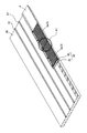
さらに、本実施形態の樋部22は、樋延長部材65の内側空間に挿通したとき、略丁度嵌り込む形状となっている。言い換えると、樋部22と樋延長部材65の重なり部では、樋部22の少なくとも一部と樋延長部材65の一部とが密着嵌合した状態となっている。
つまり、樋延長部材65の底板形成部70の幅(左右方向における長さ)は、樋部22の樋底板部22aの幅(左右方向における長さ)よりも僅かに長くなっている。また、樋延長部材65の外側側壁部72の上下方向の長さは、樋底板部22aの外側樋側壁部22cの上下方向の長さよりも長くなっている。具体的には、側壁形成板部72aの長さが、外側樋側壁部22cの上下方向の長さよりも長くなっている。
以上のことから、樋部22を樋延長部材65の内側空間に挿通したとき、樋部22における樋底板部22aの下面と、樋延長部材65における底板形成部70の上面とが密着した状態となる。同様に、樋部22における内側樋側壁部22dの外側面と、樋延長部材65における内側側壁部71の内側面が密着した状態となり、樋部22における外側樋側壁部22cの外側面と、樋延長部材65における外側側壁部72の内側面が密着した状態となる。
Further, the collar portion 22 of the present embodiment has a shape that fits almost exactly when inserted into the inner space of the collar extension member 65. In other words, at the overlapping portion of the collar portion 22 and the collar extension member 65, at least a part of the collar portion 22 and a part of the collar extension member 65 are in close contact with each other.
That is, the width (length in the left-right direction) of the bottom plate forming portion 70 of the heel extension member 65 is slightly longer than the width (length in the left-right direction) of the heel bottom plate portion 22a of the heel portion 22. Further, the vertical length of the outer side wall portion 72 of the eaves extension member 65 is longer than the vertical length of the outer side wall portion 22c of the eaves bottom plate portion 22a. Specifically, the length of the side wall forming plate portion 72a is longer than the length of the outer side wall side wall portion 22c in the vertical direction.
From the above, when the collar part 22 is inserted into the inner space of the collar extension member 65, the bottom surface of the collar bottom plate part 22a in the collar part 22 and the upper surface of the bottom plate forming part 70 in the collar extension member 65 are in close contact with each other. Become. Similarly, the outer side surface of the inner side wall side wall portion 22d of the flange portion 22 and the inner side surface of the inner side wall portion 71 of the flange extension member 65 are in close contact with each other, and the outer side surface of the outer side wall side wall portion 22c of the flange portion 22 The inner side surface of the outer side wall portion 72 of the extension member 65 is in close contact.

なお、樋部22の前方傾斜部46(図6等参照)は、上記したように、樋底板部22aの前端部分(軒側端部)を下方側へ僅かに折り曲げることで、形成されている。
このため、この前方傾斜部46は弾性変形が可能な部分となっており、樋延長部材65の装着時には、下方側から樋延長部材65の底板形成部70を添え当てられることで変形し、この底板形成部70の上面に沿って前方側へ延びる形状となる。すなわち、変形した前方傾斜部46の下面と、底板形成部70の上面とが密着(又は略密着)した状態となる。
In addition, the front inclination part 46 (refer FIG. 6 etc.) of the collar part 22 is formed by slightly bending the front-end part (eave side edge part) of the collar bottom board part 22a below as mentioned above. .
Therefore, the front inclined portion 46 is a portion that can be elastically deformed. When the heel extension member 65 is attached, the front inclined portion 46 is deformed by attaching the bottom plate forming portion 70 of the heel extension member 65 from the lower side. The shape extends to the front side along the upper surface of the bottom plate forming portion 70. In other words, the deformed lower surface of the front inclined portion 46 and the upper surface of the bottom plate forming portion 70 are in close contact (or substantially in close contact).

また、樋部22を樋延長部材65の内側空間に挿通した状態では、規制板部72bが、樋延長部材65の下方への移動を規制するための規制部として機能する。
すなわち、樋延長部材65を樋部22に取り付けた状態において、樋延長部材65が重力等により下方側へと落下しようとしても、樋延長部材65の規制板部72bの下面が、樋部22の外側樋側壁部22cの上端と当接することで、その移動を規制する。このことにより、樋延長部材65の脱落等を防止可能となり、樋部22に樋延長部材65を取り付けたまま、太陽電池モジュール3の持ち運びが可能となる。
Further, in a state where the collar portion 22 is inserted into the inner space of the collar extension member 65, the regulation plate portion 72 b functions as a regulation section for regulating the downward movement of the collar extension member 65.
That is, in the state where the heel extension member 65 is attached to the heel part 22, even if the heel extension member 65 attempts to drop downward due to gravity or the like, the lower surface of the restriction plate part 72 b of the heel extension member 65 is The movement is regulated by coming into contact with the upper end of the outer flange side wall portion 22c. As a result, it is possible to prevent the eaves extension member 65 from falling off, and the solar cell module 3 can be carried with the eaves extension member 65 attached to the eaves portion 22.

瓦部材4は、図8、図9で示されるように、金属製の板体を適宜折り曲げて形成される屋根板であり、軒端側下方に位置する軒側瓦掛止部85(屋根材軒側掛止部)と、平板状の瓦本体板部86と、棟側瓦掛止部87(屋根材棟側掛止部)を備えた構造となっている。加えて、瓦部材4の後端部(棟側端部)よりやや前方に位置する部分には、瓦部材4を屋根上に固定するため瓦取付孔88が設けられている。この瓦取付孔88は、複数(図8では2つ)形成されており、左右方向で間隔を空けて並列するように形成されている。
さらに、瓦本体板部86の裏面には、図9で示されるように、瓦下発泡断熱材89が取り付けられている。
As shown in FIGS. 8 and 9, the tile member 4 is a roof plate formed by appropriately bending a metal plate, and the eaves side tile hooking portion 85 (roof material eaves) located below the eave end side. Side latching portion), a flat tile body plate portion 86, and a ridge side tile latching portion 87 (roof material ridge side latching portion). In addition, a tile mounting hole 88 is provided in a portion located slightly ahead of the rear end portion (ridge side end portion) of the tile member 4 in order to fix the tile member 4 on the roof. A plurality (two in FIG. 8) of the tile mounting holes 88 are formed, and are formed so as to be arranged in parallel at intervals in the left-right direction.
Furthermore, as shown in FIG. 9, an under-tile foam heat insulating material 89 is attached to the back surface of the tile main body plate portion 86.

軒側瓦掛止部85は、瓦本体板部86の前端側(軒端側)を下方側に折り曲げた後、さらにその下端側を後方へ折り曲げて形成される部分である。
すなわち、軒側瓦掛止部85は、瓦本体板部86の前端側から下方に延びる立板状の部分と、この立板状の部分の下端から後方へ延びる平板状の部分とを備えており、下方側へと延びた後に後方側へと延びる鉤状の部分となっている。
The eaves side tile retaining portion 85 is a portion formed by bending the front end side (eave end side) of the tile main body plate portion 86 downward and further bending the lower end side rearward.
That is, the eaves side tile hooking portion 85 includes a vertical plate-like portion extending downward from the front end side of the tile main body plate portion 86 and a flat plate-like portion extending rearward from the lower end of the vertical plate-like portion. It is a bowl-shaped portion that extends downward and then extends backward.

瓦本体板部86の左右方向における両端部分のそれぞれには、左右方向における端部を下方側へ折り曲げて形成される立板状の瓦側壁部90が設けられている。
瓦側壁部90は、その下端の高さが軒側瓦掛止部85の下端の高さよりも高くなっており、瓦部材4の前端(軒端)よりもやや後方(棟側)に位置する部分から、瓦部材4の後端よりもやや前方に位置する部分までの間で延びている。
Each of both end portions in the left-right direction of the tile main body plate portion 86 is provided with a standing-plate-like roof tile side wall portion 90 formed by bending an end portion in the left-right direction downward.
The tile side wall 90 has a lower end that is higher than the lower end of the eaves side tile hook 85 and is located slightly rearward (ridge side) from the front end (eave end) of the tile member 4. To a portion located slightly forward of the rear end of the roof tile member 4.

棟側瓦掛止部87は、金属製の板体の一部を表面側に凸となるように折り曲げて形成される部分であり、瓦部材4の表裏方向において裏面側から表面側へ向かう方向(下側から上側へ向かう方向)に突出するように形成された立板状の突出壁部87aと、突出壁部87aの上端から前方(軒側)へ向かう方向に突出するように形成された平板状の上側板部87bを備えた構造となっている。すなわち、棟側瓦掛止部87は、側面視した形状が略「L」字状となり、左右方向に延びる部分となっている。   The ridge-side tile hooking portion 87 is a portion formed by bending a part of a metal plate so as to be convex on the front side, and in the front and back direction of the roof tile member 4, the direction from the back side to the front side. A protruding plate-like protruding wall portion 87a formed so as to protrude in the direction from the lower side to the upper side, and formed so as to protrude in the direction from the upper end of the protruding wall portion 87a toward the front side (eave side). It has a structure provided with a flat upper plate part 87b. That is, the ridge-side tile retaining portion 87 has a substantially “L” shape when viewed from the side, and is a portion extending in the left-right direction.

瓦下発泡断熱材89は、図9で示されるように、発泡樹脂製の部材の表面を適宜アルミ膜等で覆って形成されるものであり、外形が略直方体状となっている。より具体的には、この瓦下発泡断熱材89は、後側(棟側)に向かうにつれてその厚さが薄くなっていくように形成しており、且つ、前端側(軒端側)上方に位置する角部分を欠落させて丸みを帯びた形状とすると共に、後端側(棟端側)上方に位置する角部分を欠落させて傾斜面を形成している。
また、この瓦下発泡断熱材89は、瓦部材4の長手方向(左右方向)における片側端部側の部分を欠落させた形状となっている。すなわち、この瓦下発泡断熱材89は、長手方向の片側端部からやや中心側に離れた位置から、他方端部の近傍に至る位置まで延びている。言い換えると、瓦下発泡断熱材89の長手方向における片側端部は、瓦部材4の長手方向における片側端部よりもやや中心側に位置しており、瓦下発泡断熱材89の長手方向における他方端部は、瓦部材4の長手方向における他方端部の近傍に位置している(略同一の位置に配されている)。
つまり、瓦下発泡断熱材89が瓦部材4の左右方向における他方端部よりに配されており、瓦部材4の長手方向における片側端部の周辺には、瓦下発泡断熱材89が取り付けられていない部分である樋部配置領域91が形成されている。
As shown in FIG. 9, the under-tile foam heat insulating material 89 is formed by appropriately covering the surface of a foamed resin member with an aluminum film or the like, and has a substantially rectangular parallelepiped shape. More specifically, the under-foam foam heat insulating material 89 is formed so that its thickness becomes thinner toward the rear side (ridge side), and is positioned above the front end side (eave end side). The corner portion to be cut off is formed into a rounded shape, and the inclined portion is formed by removing the corner portion positioned above the rear end side (ridge end side).
Further, the under-brick foam heat insulating material 89 has a shape in which a portion on one end side in the longitudinal direction (left-right direction) of the roof tile member 4 is omitted. That is, the under-brick foam heat insulating material 89 extends from a position slightly distant from the one end portion in the longitudinal direction to a position reaching the vicinity of the other end portion. In other words, the one end portion in the longitudinal direction of the under-tile foam heat insulating material 89 is located slightly closer to the center side than the one end portion in the longitudinal direction of the tile member 4, and the other end in the longitudinal direction of the under-tile foam heat insulating material 89. The end portion is located in the vicinity of the other end portion in the longitudinal direction of the roof tile member 4 (arranged at substantially the same position).
That is, the under-brick foam heat insulating material 89 is arranged from the other end portion in the left-right direction of the tile member 4, and the under-brick foam heat insulating material 89 is attached around one end portion in the longitudinal direction of the tile member 4. A buttocks arrangement area 91 that is not a part is formed.

樋部配置領域91は、瓦下発泡断熱材89の片側端部と、瓦側壁部90の間に形成される部分であり、その左右方向(幅方向)の長さが上記した樋部22の左右方向の長さよりもやや長くなっている。さらに具体的には、その左右方向(幅方向)の長さが、樋部22に樋延長部材65を装着して形成される雨水流通路80(図6等参照)の左右方向(幅方向)の長さよりもやや長くなっている。この樋部配置領域91では、瓦下発泡断熱材89が取り付けられた部分よりもその厚さが薄くなっている。   The collar part arrangement | positioning area | region 91 is a part formed between the one side edge part of the under-brick foam heat insulating material 89, and the tile side wall part 90, The length of the left-right direction (width direction) of the collar part 22 mentioned above It is slightly longer than the length in the left-right direction. More specifically, the length in the left-right direction (width direction) is the left-right direction (width direction) of the rainwater flow passage 80 (see FIG. 6 and the like) formed by attaching the heel extension member 65 to the heel portion 22. It is slightly longer than the length of. In this collar part arrangement | positioning area | region 91, the thickness is thinner than the part to which the under-sill foam insulation material 89 was attached.

続いて、本実施形態の屋根構造1について、施工手順に沿って詳細に説明する。   Then, the roof structure 1 of this embodiment is demonstrated in detail along a construction procedure.

まず、図10で示されるように、屋根下地95の軒側端部に対し、軒先金具2を取り付けていく工程を実施する。なお、作図の都合上、軒先金具2の一部にのみ符号を付し、その他への符号を省略する。   First, as shown in FIG. 10, a process of attaching the eaves edge fitting 2 to the eaves side end of the roof base 95 is performed. For the sake of drawing, only a part of the eaves metal fitting 2 is given a reference numeral, and the other reference numerals are omitted.

屋根下地95は、所定角度で傾斜した敷設対象となる建屋の屋根面に、軒先水切り(図示しない)や防水シート等のルーフィング材(図示しない)が取り付けられ、さらに、縦桟木(図示しない)、横桟木97、広小舞98(図10では図示しない、図11参照)が取り付けられて形成されている。
また、軒先金具2は、図11で示されるように、広小舞98に対して固定されるものであり、広小舞98の上に配した状態で、取付孔14(図2参照)に締結要素を挿通し、一体に固定している。
The roof foundation 95 is attached to a roof surface of a building to be laid at a predetermined angle by a roofing material (not shown) such as an eaves drain (not shown) or a waterproof sheet, and further, a vertical pier (not shown), A horizontal crosspiece 97 and Hirokomai 98 (not shown in FIG. 10, refer to FIG. 11) are attached and formed.
Further, as shown in FIG. 11, the eaves-end metal fitting 2 is fixed to the wide Komai 98, and is arranged on the wide Komai 98 in the mounting hole 14 (see FIG. 2). The fastening element is inserted and fixed integrally.

本実施形態では、図10で示されるように、左右方向(桁行方向)に沿って複数の軒先金具2が並列するように固定されている。   In the present embodiment, as shown in FIG. 10, a plurality of eaves-end fittings 2 are fixed in parallel along the left-right direction (the column direction).

続いて、軒先金具2を取り付けた屋根下地95に対し、軒側第1段目に属する瓦部材4と太陽電池モジュール3を固定する工程を実施する。
軒側第1段目に属する瓦部材4を固定する際には、図12で示されるように、瓦部材4の軒側瓦掛止部85(図8等参照)を複数の軒先金具2の掛止空間17(図11参照)に挿通し、瓦部材4の軒側部分を複数の軒先金具2に引っ掛けた状態とする。言い換えると、瓦部材4の軒側部分を外部部材である軒先金具2に掛止した状態とする。そして、瓦部材4の軒側部分を回動支点として、棟側部分が下方へ向かう方向に回動させる。さらに、桁行方向(左右方向)にスライド移動させ、瓦部材4を設置位置まで移動させると、その棟側部分に締結要素を挿通し、屋根下地95の上に固定する。
すなわち、スライド移動後、図13で示されるように、瓦部材4の瓦取付孔88を横桟木97と重ねた状態とし、これらに締結要素を挿通させることで、瓦部材4を屋根下地95の上に一体に固定する。
Then, the process of fixing the tile member 4 and the solar cell module 3 which belong to the eaves side 1st step with respect to the roof base | substrate 95 which attached the eaves-end metal fitting 2 is implemented.
When fixing the roof tile member 4 belonging to the first eaves side first stage, as shown in FIG. 12, the roof side tile latching portion 85 (see FIG. 8, etc.) of the roof tile member 4 is attached to the plurality of eaves end brackets 2. It is assumed that the eaves side portion of the roof tile member 4 is hooked on the plurality of eaves end fittings 2 through the hooking space 17 (see FIG. 11). In other words, the eaves side portion of the roof tile member 4 is in a state of being hooked to the eaves tip metal fitting 2 which is an external member. And the ridge side part is rotated in the direction which goes below using the eaves side part of the tile member 4 as a rotation fulcrum. Further, when the tile member 4 is moved to the installation position by sliding in the column direction (left and right direction), the fastening element is inserted into the ridge side portion and fixed on the roof base 95.
That is, after the slide movement, as shown in FIG. 13, the tile mounting holes 88 of the roof tile member 4 are overlapped with the cross beams 97, and the fastening elements are inserted through these to make the roof tile 95 the roof tile 95. Fasten together on top.

軒側第1段目に属する太陽電池モジュール3を固定する際には、図14で示されるように、太陽電池モジュール3のモジュール軒側掛止部50(図3、図5等参照)を複数の軒先金具2の掛止空間17(図11参照)に挿通し、軒先金具2に引っ掛けた状態とする。このとき、雨水流通路80の軒端に位置する延長樋掛止部73(図6等参照)もまた、必要に応じて軒先金具2に引っ掛けた状態とする。つまり、太陽電池モジュール3の軒側部分を外部部材である軒先金具2に引っ掛けた状態とする。そして、太陽電池モジュール3の軒側部分を回動支点として、棟側部分が下方へ向かう方向に回動させる。さらに、桁行方向(左右方向)にスライド移動させ、太陽電池モジュール3を設置位置まで移動させると、その棟側部分に締結要素を挿通し、屋根下地95の上に固定する。
より具体的には、スライド移動後、押さえ板部材33に形成した取付用孔(図示しない)と、横桟木97とが上下方向で重なる状態とし、これらに締結要素を挿通させることで、太陽電池モジュール3を屋根下地95の上に一体に固定する。
When the solar cell module 3 belonging to the first eave side first stage is fixed, as shown in FIG. 14, a plurality of module eaves side latching portions 50 (see FIGS. 3 and 5) of the solar cell module 3 are provided. It is inserted into the hooking space 17 (see FIG. 11) of the eaves-end fitting 2 and is hooked on the eaves-end fitting 2. At this time, the extended hook locking portion 73 (see FIG. 6 and the like) located at the eaves end of the rainwater flow passage 80 is also in a state of being hooked to the eaves fitting 2 as necessary. That is, it is set as the state which hooked the eaves side part of the solar cell module 3 on the eaves tip metal fitting 2 which is an external member. And the eaves side part of the solar cell module 3 is made to rotate in the direction which a ridge side part goes to the downward direction using a rotation fulcrum. Further, when the solar cell module 3 is moved to the installation position by sliding in the column direction (left and right direction), the fastening element is inserted into the ridge side portion and fixed on the roof base 95.
More specifically, after the slide movement, a mounting hole (not shown) formed in the pressing plate member 33 and the horizontal crosspiece 97 overlap each other in the vertical direction, and a fastening element is inserted through these, so that the solar cell The module 3 is fixed integrally on the roof base 95.

このように、軒側第1段目に属する瓦部材4と太陽電池モジュール3をそれぞれ固定していく。
ここで、本実施形態における屋根構造1の軒側第1段目では、図1等で示されるように、桁行方向における両外側に瓦部材4を固定し、その間に複数の太陽電池モジュール3が桁行方向に並列された状態で固定される構造としている。
In this manner, the roof tile member 4 and the solar cell module 3 belonging to the first eave side first stage are fixed.
Here, in the first stage on the eaves side of the roof structure 1 in the present embodiment, as shown in FIG. 1 and the like, the roof tile members 4 are fixed to both outer sides in the crossing direction, and a plurality of solar cell modules 3 are interposed therebetween. It is structured to be fixed in a state of being aligned in the column direction.

したがって、図15、図16で示されるように、軒側第1段目における1つ目の太陽電池モジュール3aを固定した後、左右方向(桁行方向)で隣接する位置に、2つ目の太陽電池モジュール3bを固定する。この2つ目の太陽電池モジュール3bもまた、上記した1つ目の太陽電池モジュール3aの固定と同様の手順で固定する。   Therefore, as shown in FIG. 15 and FIG. 16, after fixing the first solar cell module 3 a in the first stage on the eave side, the second solar cell is positioned adjacent to the left and right direction (column direction). The battery module 3b is fixed. The second solar cell module 3b is also fixed in the same procedure as the fixing of the first solar cell module 3a described above.

ここで、1つ目の太陽電池モジュール3aと、2つ目の太陽電池モジュール3bの境界となる部分(例えば、図16のA1で示される部分)に注目すると、1つ目の太陽電池モジュール3aの樋部22を含む雨水流通路80(図15参照)が、図16で示されるように、2つ目の太陽電池モジュール3bの下方に位置した状態となっている。
具体的には、1つ目の太陽電池モジュール3aに属する雨水流通路80が、2つ目の太陽電池モジュール3bの樋部配置領域58(図4参照)に収納された状態となっている。
Here, when attention is paid to a portion (for example, a portion indicated by A1 in FIG. 16) serving as a boundary between the first solar cell module 3a and the second solar cell module 3b, the first solar cell module 3a. As shown in FIG. 16, the rainwater flow passage 80 (see FIG. 15) including the flange portion 22 is located below the second solar cell module 3 b.
Specifically, the rainwater flow path 80 belonging to the first solar cell module 3a is in a state of being housed in the heel arrangement region 58 (see FIG. 4) of the second solar cell module 3b.

このことから、図17で示されるように、1つ目の太陽電池モジュール3aに属する雨水流通路80の軒端よりさらに軒側には、2つ目の太陽電池モジュール3bのフロントカバー31(前方保護板部48)が位置し、上端よりもさらに上側には、2つ目の太陽電池モジュール3bの太陽電池モジュール本体部63が位置している。
つまり、1つ目の太陽電池モジュール3aに属する雨水流通路80の前方(軒側)及び上方が、隣接配置される2つ目の太陽電池モジュール3bによって覆われた状態となっており、略全ての部分が外部に露出することのない構造となっている。言い換えると、1つ目の太陽電池モジュール3aに属する雨水流通路80の後端(棟側端部)から前端(軒側端部)に至る全域の上方と、その前方に、2つ目の太陽電池モジュール3b(太陽電池モジュール本体部63)が位置した状態となっている。
From this, as shown in FIG. 17, the front cover 31 (front protection) of the second solar cell module 3b is located further on the eaves side than the eaves end of the rainwater flow passage 80 belonging to the first solar cell module 3a. The plate portion 48) is located, and the solar cell module main body 63 of the second solar cell module 3b is located further above the upper end.
That is, the front (eave side) and the upper side of the rainwater flow passage 80 belonging to the first solar cell module 3a are covered with the second solar cell module 3b arranged adjacent to each other, and almost all This part has a structure that is not exposed to the outside. In other words, the second solar cell is located above and in front of the entire area from the rear end (ridge side end) to the front end (eave side end) of the rainwater flow passage 80 belonging to the first solar cell module 3a. The battery module 3b (solar cell module main body 63) is positioned.

続いて、図18、図19で示されるように、2つ目の太陽電池モジュール3bと隣接する位置に3つ目の太陽電池モジュール3cを固定し、さらに、3つ目の太陽電池モジュール3cと隣接する位置に2つ目の瓦部材4を固定する。
なお、このとき、3つ目の太陽電池モジュール3bもまた、上記した1つ目の太陽電池モジュール3aの固定と同様の手順で固定し、2つ目の瓦部材4bもまた、上記した瓦部材4(一つ目の瓦部材4a)の固定と同様の手順で固定する。
Subsequently, as shown in FIG. 18 and FIG. 19, the third solar cell module 3c is fixed to a position adjacent to the second solar cell module 3b, and further, the third solar cell module 3c The second roof tile member 4 is fixed at an adjacent position.
At this time, the third solar cell module 3b is also fixed in the same procedure as the fixing of the first solar cell module 3a, and the second tile member 4b is also fixed to the above-described tile member. 4 (first roof tile member 4a) is fixed in the same procedure.

このとき、2つ目の太陽電池モジュール3bと、3つ目の太陽電池モジュール3cの境界部分でもまた、上記と同様に、2つ目の太陽電池モジュール3bに属する雨水流通路80が、3つ目の太陽電池モジュール3cの樋部配置領域58(図4参照)に収納された状態となっている。   At this time, at the boundary portion between the second solar cell module 3b and the third solar cell module 3c, there are also three rainwater flow passages 80 belonging to the second solar cell module 3b as described above. It is in the state of being housed in the buttocks arrangement region 58 (see FIG. 4) of the solar cell module 3c of the eye.

そして、3つ目の太陽電池モジュール3cと2つ目の瓦部材4bの境界となる部分(例えば、図19のA2で示される部分)に注目すると、図20で示されるように、3つ目の太陽電池モジュール3cの樋部22を含む雨水流通路80が、2つ目の瓦部材4bの下方に位置した状態となっている。
具体的には、3つ目の太陽電池モジュール3cに属する雨水流通路80が、2つ目の瓦部材4bの樋部配置領域91(図9参照)に収納された状態となっている。
When attention is paid to a portion (for example, a portion indicated by A2 in FIG. 19) serving as a boundary between the third solar cell module 3c and the second roof tile member 4b, as shown in FIG. The rainwater flow path 80 including the flange portion 22 of the solar cell module 3c is located below the second roof tile member 4b.
Specifically, the rainwater flow path 80 belonging to the third solar cell module 3c is in a state of being housed in the heel arrangement region 91 (see FIG. 9) of the second roof tile member 4b.

このことから、図20で示されるように、3つ目の太陽電池モジュール3cに属する雨水流通路80の軒端よりさらに軒側に、2つ目の瓦部材4bの軒側瓦掛止部85が位置し、上端よりもさらに上側には、2つ目の瓦部材4bの瓦本体板部86が位置している。
つまり、3つ目の太陽電池モジュール3cに属する雨水流通路80の前方(軒側)及び上方が、隣接配置される2つ目の瓦部材4bによって覆われた状態となっており、略全ての部分が外部に露出することのない構造となっている。言い換えると、3つ目の太陽電池モジュール3cに属する雨水流通路80の後端(棟側端部)から前端(軒側端部)に至る全域の上方と、その前方に、2つ目の瓦部材4bが位置した状態となっている。
From this, as shown in FIG. 20, the eaves-side tile hooking portion 85 of the second tile member 4b is further on the eaves side than the eaves end of the rainwater flow passage 80 belonging to the third solar cell module 3c. The tile main body plate portion 86 of the second tile member 4b is located further above the upper end.
That is, the front (eave side) and upper side of the rainwater flow passage 80 belonging to the third solar cell module 3c are covered with the second tile member 4b arranged adjacent to each other, and almost all The structure is such that the portion is not exposed to the outside. In other words, the second tile is located above and in front of the entire area from the rear end (ridge side end) to the front end (eave side end) of the rainwater flow passage 80 belonging to the third solar cell module 3c. The member 4b is in a positioned state.

以上で、軒側第1段目に属する瓦部材4と太陽電池モジュール3を固定する工程が完了する。これに続いて、軒側第2段目に属する瓦部材4と太陽電池モジュール3を固定する工程を実施する。   This completes the process of fixing the roof tile member 4 and the solar cell module 3 belonging to the first eaves side. Following this, a step of fixing the roof tile member 4 and the solar cell module 3 belonging to the second eave side stage is performed.

軒側第2段目に属する瓦部材4を固定する際には、例えば、図21で示されるように、軒側第2段目に属する瓦部材4cの軒側瓦掛止部85を、軒側第1段目に属する瓦部材4aの棟側瓦掛止部87と、軒側第1段目に属する太陽電池モジュール3aのモジュール棟側掛止部59とに引っ掛けた状態とする。すなわち、軒側瓦掛止部85の一部を棟側瓦掛止部87に引っ掛け、他の一部をモジュール棟側掛止部59に引っ掛けた状態とする。
そして、軒側第2段目に属する瓦部材4cの軒側部分を回動支点として、棟側部分が下方へ向かう方向に回動させる。さらに、桁行方向(左右方向)にスライド移動させ、軒側第2段目に属する瓦部材4cを設置位置まで移動させると、その棟側部分に締結要素を挿通し、屋根下地95の上に固定する。
すなわち、軒側瓦掛止部85を外部部材に引っ掛けて回動させ、さらにスライド移動させた後に、図22で示されるように、瓦部材4cの瓦取付孔88を横桟木97と重ねた状態とし、これらに締結要素を挿通させることで、瓦部材4cを屋根下地95の上に一体に固定する。
When fixing the roof tile member 4 belonging to the eaves-side second stage, for example, as shown in FIG. It is set as the state hooked on the ridge side tile latching part 87 of the tile member 4a belonging to the first side of the side and the module ridge side latching part 59 of the solar cell module 3a belonging to the first stage of the eaves side. That is, a part of the eaves side tile hooking portion 85 is hooked on the ridge side tile hooking portion 87 and the other part is hooked on the module ridge side hooking portion 59.
Then, the eaves side portion of the roof tile member 4c belonging to the eaves side second stage is rotated in the direction in which the ridge side portion is directed downward, with the rotation side fulcrum as a rotation fulcrum. Furthermore, when the tile member 4c belonging to the eave side second stage is moved to the installation position by sliding in the column direction (left and right direction), a fastening element is inserted into the ridge side portion and fixed on the roof base 95. To do.
That is, after the eaves-side tile hooking portion 85 is hooked on an external member, rotated, and further slid, as shown in FIG. 22, the tile attachment hole 88 of the tile member 4c is overlapped with the horizontal beam 97. The tile member 4c is integrally fixed on the roof base 95 by inserting fastening elements through them.

軒側第2段目に属する太陽電池モジュール3を固定する際には、例えば、図23で示されるように、軒側第2段目に属する太陽電池モジュール3dのモジュール軒側掛止部50(図3、図5等参照)を、軒側第1段目において隣接配置される2つの太陽電池モジュール3(太陽電池モジュール3a、太陽電池モジュール3b)のモジュール棟側掛止部59に引っ掛けた状態とする。すなわち、モジュール軒側掛止部50の一部を、一方の太陽電池モジュール3aのモジュール棟側掛止部59に引っ掛け、モジュール軒側掛止部50の他の一部を、他方の太陽電池モジュール3bのモジュール棟側掛止部59に引っ掛けた状態とする。
そして、軒側第2段目に属する太陽電池モジュール3の軒側部分を回動支点として、棟側部分が下方へ向かう方向に回動させる。さらに、桁行方向(左右方向)にスライド移動させ、太陽電池モジュール3を設置位置まで移動させると、その棟側部分に締結要素を挿通し、屋根下地95の上に固定する(図24参照)。
より具体的には、モジュール軒側掛止部50を外部部材に引っ掛けて回動させ、さらにスライド移動させた後に、押さえ板部材33に形成した取付用孔(図示しない)と、横桟木97とが上下方向で重なる状態とし、これらに締結要素を挿通させることで、太陽電池モジュール3を屋根下地95の上に一体に固定する。
When fixing the solar cell module 3 belonging to the eaves-side second stage, for example, as shown in FIG. 23, the module eaves side latching portion 50 ( 3, FIG. 5, etc.) are hooked on the module building side latching portion 59 of two solar cell modules 3 (solar cell module 3 a, solar cell module 3 b) that are adjacently arranged in the first eave side. And That is, a part of the module eaves side latching part 50 is hooked on the module building side latching part 59 of one solar cell module 3a, and the other part of the module eaves side latching part 50 is hooked on the other solar cell module. It is assumed that it is hooked on the module building side latching portion 59 of 3b.
Then, the eaves-side portion of the solar cell module 3 belonging to the eave-side second stage is rotated in the direction in which the ridge-side portion is directed downward, using the rotation fulcrum as a rotation fulcrum. Further, when the solar cell module 3 is moved to the installation position by sliding in the column direction (left and right direction), the fastening element is inserted into the ridge side portion and fixed on the roof base 95 (see FIG. 24).
More specifically, after the module eaves side latching part 50 is hooked on the external member, rotated, and further slid, the mounting hole (not shown) formed in the pressing plate member 33, the cross beam 97, Are overlapped in the vertical direction, and a fastening element is inserted through them to fix the solar cell module 3 integrally on the roof base 95.

以上のように、軒側第2段目に属する瓦部材4や太陽電池モジュール3を固定する工程では、これらを回動させる位置、言い換えると、設置位置から桁行方向にずれた位置において、その軒側に固定されている瓦部材4や太陽電池モジュール3に対して軒側部分を引っ掛けた状態とし、その後に回動させている。つまり、軒側第1段目において、隣接配置される瓦部材4と太陽電池モジュール3からなる組や、2つの太陽電池モジュール3からなる組に対して引っ掛けた状態とし、回動させている。
したがって、詳しくは後述するが、軒側第1段目において2つの瓦部材4を桁行方向に隣接配置させた場合等においては、軒側第2段目に属する瓦部材4や太陽電池モジュール3の軒側端部を、2つの瓦部材4に対して引っ掛けた状態とし、回動させてもよい。つまり、軒側第2段目に属する瓦部材4や太陽電池モジュール3を回動させる位置において、その軒側に位置する瓦部材4と太陽電池モジュール3のいずれか一方又は双方からなる1以上の部材に対して引っ掛けた状態とし、その後に回動させればよい。
As described above, in the step of fixing the roof tile member 4 and the solar cell module 3 belonging to the second stage of the eaves side, in the position where they are rotated, in other words, in the position shifted in the direction of the column from the installation position. The eaves side portion is hooked on the roof tile member 4 and the solar cell module 3 fixed on the side, and then rotated. In other words, in the first stage on the eaves side, the state is hooked and rotated with respect to a group composed of the tile member 4 and the solar cell module 3 arranged adjacent to each other or a group composed of the two solar cell modules 3.
Therefore, as will be described in detail later, in the case where two roof tile members 4 are arranged adjacent to each other in the first row of the eaves side, the roof tile members 4 and the solar cell modules 3 belonging to the second stage of the eaves side are arranged. The eaves side end may be hooked on the two roof tile members 4 and rotated. That is, at the position where the roof tile member 4 and the solar cell module 3 belonging to the second eave side are rotated, one or more of the roof tile member 4 and the solar cell module 3 located on the eave side are provided. What is necessary is just to make it the state hooked with respect to the member, and to rotate after that.

ここで、図1等で示されるように、本実施形態の屋根構造1における軒側第2段目でもまた、桁行方向における両外側に瓦部材4を固定し、その間に複数の太陽電池モジュール3が並列するように固定された構造としている。   Here, as shown in FIG. 1 and the like, the roof member 1 of the roof structure 1 of the present embodiment also has the roof member 1 on the eaves side second stage, and the roof tile members 4 are fixed to both outer sides in the crossing direction, and a plurality of solar cell modules 3 are interposed therebetween. Are fixed in parallel.

したがって、軒側第1段目と同様に、軒側第2段目においても、1つ目の瓦部材4cを固定した後、桁行方向の一端側から順に複数の太陽電池モジュール3を固定していき、その後に、2つ目の瓦部材4dを固定する。   Therefore, similarly to the first stage on the eave side, after fixing the first roof tile member 4c in the second stage on the eave side, a plurality of solar cell modules 3 are fixed in order from one end side in the row direction. Then, the second roof tile member 4d is fixed.

なお、本実施形態の屋根構造1では、軒棟方向(屋根の傾斜方向)で隣接する2つの瓦部材4は、その桁行方向(左右方向)における両端位置が揃った状態で取り付けている。つまり、軒側第1段目に位置する瓦部材4aの上方には、軒側第2段目に位置する瓦部材4cが位置しており、且つ、軒側の瓦部材4aの桁行方向における両端部のそれぞれと棟側で隣接する位置に、棟側の瓦部材4cの桁行方向における両端部のそれぞれが位置している。
これと同様に、軒棟方向で隣接する太陽電池モジュール3同士の桁行方向における両端位置もまた、揃った状態となっている。
In addition, in the roof structure 1 of this embodiment, the two tile members 4 adjacent in the eaves ridge direction (roof inclination direction) are attached in a state where both end positions in the row direction (left and right direction) are aligned. That is, above the roof tile member 4a located on the first eave side, the roof tile member 4c located on the second eave side is located, and both ends of the roof tile member 4a in the row direction are located. Each of the both ends of the roof tile tile 4c in the direction of the row is located at a position adjacent to each of the sections on the ridge side.
Similarly, the both end positions in the column direction of the solar cell modules 3 adjacent in the eaves-ridge direction are also aligned.

ここで、図24、図25で示されるように、軒側第2段目における1つ目の太陽電池モジュール3dが設置位置に配された状態では、この太陽電池モジュール3dの太陽電池モジュール本体部63の軒側には、軒側第1段目で隣接配置される2つの太陽電池モジュール3の一方(太陽電池モジュール3a)が位置している。対して、この太陽電池モジュール3dの雨水流通路80の軒端には、2つの太陽電池モジュール3の他方(太陽電池モジュール3b)が位置している。   Here, as shown in FIG. 24 and FIG. 25, in the state where the first solar cell module 3 d in the second eave side second stage is arranged at the installation position, the solar cell module main body of this solar cell module 3 d On one side of the eave 63, one of the two solar cell modules 3 (solar cell module 3a) adjacently disposed in the first eave side is located. On the other hand, the other of the two solar cell modules 3 (solar cell module 3b) is located at the eaves end of the rainwater flow passage 80 of the solar cell module 3d.

すなわち、軒側第2段目における1つ目の太陽電池モジュール3dのモジュール軒側掛止部50(図3等参照)は、軒側第1段目で隣接配置される一方の太陽電池モジュール3aのモジュール棟側掛止部59(図23等参照)に掛止されている。
そして、太陽電池モジュール3dの延長樋掛止部73は、図25で示されるように、隣接配置される他方の太陽電池モジュール3bのモジュール棟側掛止部59に掛止されている。言い換えると、延長樋掛止部73を外部部材であるモジュール棟側掛止部59に掛止している。
That is, the module eaves side latching part 50 (refer FIG. 3 etc.) of the 1st solar cell module 3d in the eaves side 2nd step | paragraph is one solar cell module 3a adjacently arranged by the eaves side 1st step | paragraph. The module building side latching portion 59 (see FIG. 23, etc.).
Then, as shown in FIG. 25, the extended rod hooking portion 73 of the solar cell module 3d is hooked to the module building side hooking portion 59 of the other solar cell module 3b that is adjacently disposed. In other words, the extended hook latching portion 73 is latched to the module building side latching portion 59 which is an external member.

なお、軒側第1段目の太陽電池モジュール3aを基準とすると、棟側の太陽電池モジュール3dは、この太陽電池モジュール3aの外部部材となる。すなわち、軒側第1段目の太陽電池モジュール3aのモジュール棟側掛止部59に対して、外部部材となる、太陽電池モジュール3dのモジュール軒側掛止部50が掛止されているともいえる。
同様に、軒側第1段目の太陽電池モジュール3bのモジュール棟側掛止部59に対して、外部部材となる、太陽電池モジュール3dの延長樋掛止部73が掛止されているともいえる。
If the solar cell module 3a at the first eave side is used as a reference, the solar cell module 3d on the ridge side is an external member of the solar cell module 3a. That is, it can be said that the module eaves side latching part 50 of the solar cell module 3d, which is an external member, is latched to the module building side latching part 59 of the eaves side first stage solar cell module 3a. .
Similarly, it can be said that the extended hook latching portion 73 of the solar cell module 3d, which is an external member, is latched to the module building side latching portion 59 of the solar cell module 3b on the eaves side first stage. .

このことにより、軒側第2段目における1つ目の太陽電池モジュール3dの雨水流通路80の軒側端部は、軒側に隣接する太陽電池モジュール3bの棟側端部から離れた位置であり、具体的には、軒側に隣接する太陽電池モジュール3bの押さえ板部材33の軒端部分近傍となる位置の上側に固定された状態となっている。   As a result, the eaves-side end of the rainwater flow passage 80 of the first solar cell module 3d in the eave-side second stage is away from the ridge-side end of the solar cell module 3b adjacent to the eaves. Yes, specifically, it is fixed to the upper side of the position near the eave end portion of the pressing plate member 33 of the solar cell module 3b adjacent to the eave side.

続いて、図26、図27で示されるように、1つ目の太陽電池モジュール3dと隣接する位置に2つ目の太陽電池モジュール3eを固定し、さらに、2つ目の太陽電池モジュール3eと隣接する位置に3つ目の太陽電池モジュール3fを固定する。
このとき、これらの太陽電池モジュール3(太陽電池モジュール3e、太陽電池モジュール3f)もまた、上記した太陽電池モジュール3dの固定と同様の手順で固定する。
Subsequently, as shown in FIG. 26 and FIG. 27, the second solar cell module 3e is fixed at a position adjacent to the first solar cell module 3d, and the second solar cell module 3e The third solar cell module 3f is fixed at an adjacent position.
At this time, these solar cell modules 3 (solar cell module 3e and solar cell module 3f) are also fixed in the same procedure as the fixing of the solar cell module 3d described above.

ここで、軒側2段目における2つの太陽電池モジュール3の境界となる部分に注目する。図24、図26で示されるように、1つ目の太陽電池モジュール3dと、2つ目の太陽電池モジュール3eの境界となる部分では、1つ目の太陽電池モジュール3dの雨水流通路80が(図24参照)、2つ目の太陽電池モジュール3eの下方に位置した状態となっている(図26参照)。つまり、1つ目の太陽電池モジュール3dに属する雨水流通路80が、2つ目の太陽電池モジュール3eの樋部配置領域58(図4参照)に収納された状態となっている。   Here, attention is paid to a portion that becomes a boundary between the two solar cell modules 3 in the second stage on the eaves side. As shown in FIG. 24 and FIG. 26, the rainwater flow path 80 of the first solar cell module 3d is provided at the boundary between the first solar cell module 3d and the second solar cell module 3e. (Refer FIG. 24) It has been in the state located under the 2nd solar cell module 3e (refer FIG. 26). That is, the rainwater flow path 80 belonging to the first solar cell module 3d is in a state of being accommodated in the heel arrangement region 58 (see FIG. 4) of the second solar cell module 3e.

つまり、軒側第1段目における2つの太陽電池モジュール3(太陽電池モジュール3a、太陽電池モジュール3b)の境界部分と同様に、一の太陽電池モジュール3dに属する雨水流通路80の後端(棟側端部)から前端(軒側端部)に至る全域の上方と、その前方に、桁行方向で隣接配置される他の太陽電池モジュール3eが位置した状態となっている。
すなわち、図28で示されるように、軒側第2段目では、太陽電池モジュール3の軒側部分であるモジュール軒側掛止部50や延長樋掛止部73が、軒先金具2でなく、軒側に位置する太陽電池モジュール3のモジュール棟側掛止部59に掛止されている点で軒側第1段目とは異なっている。しかしながら、軒側第1段目と同様に、桁行方向に隣接配置される太陽電池モジュール3によって雨水流通路80が覆われることで、雨水流通路80が外部に露出しない構造となっている。
That is, similarly to the boundary portion between the two solar cell modules 3 (the solar cell module 3a and the solar cell module 3b) in the first stage on the eaves side, the rear end (building) of the rainwater flow passage 80 belonging to one solar cell module 3d. The other solar cell modules 3e arranged adjacent to each other in the row direction are located above and in front of the entire region from the side end) to the front end (eave end).
That is, as shown in FIG. 28, in the eave side second stage, the module eaves side hooking portion 50 and the extended eaves hooking portion 73 that are the eaves side portion of the solar cell module 3 are not the eaves end bracket 2, This is different from the first eave side first stage in that the solar cell module 3 located on the eaves side is hooked to the module building side latching portion 59. However, as in the first stage on the eaves side, the rainwater flow passage 80 is covered with the solar cell modules 3 arranged adjacent to each other in the row direction so that the rainwater flow passage 80 is not exposed to the outside.

同様に、2つ目の太陽電池モジュール3eと、3つ目の太陽電池モジュール3fの境界となる部分においても、2つ目の太陽電池モジュール3eに属する雨水流通路80が、3つ目の太陽電池モジュール3fの樋部配置領域58(図4参照)に収納された状態となっている。   Similarly, the rainwater flow path 80 belonging to the second solar cell module 3e is also the third solar cell at the boundary between the second solar cell module 3e and the third solar cell module 3f. The battery module 3f is in a state of being housed in the collar part arrangement region 58 (see FIG. 4).

ここで、図27で示されるように、軒側第2段目における3つ目の太陽電池モジュール3fが設置位置に配された状態では、この太陽電池モジュール3fの太陽電池モジュール本体部63の軒側には、軒側第1段目に配置される太陽電池モジュール3cが位置している。対して、この太陽電池モジュール3fの雨水流通路80の軒端には、軒側第1段目に配置される瓦部材4bが位置している。   Here, as shown in FIG. 27, in the state where the third solar cell module 3f in the second stage on the eave side is arranged at the installation position, the eaves of the solar cell module main body 63 of this solar cell module 3f. On the side, the solar cell module 3c arranged in the first stage on the eave side is located. On the other hand, the roof tile member 4b arranged at the eave side first stage is located at the eaves end of the rainwater flow passage 80 of the solar cell module 3f.

すなわち、軒側第2段目における3つ目の太陽電池モジュール3fのモジュール軒側掛止部50(図3等参照)は、軒側第1段目で隣接配置される太陽電池モジュール3cと瓦部材4のうち、太陽電池モジュール3cに形成されたモジュール棟側掛止部59(図23等参照)に掛止されている。そして、太陽電池モジュール3fの延長樋掛止部73は、図29で示されるように、瓦部材4bに形成された棟側瓦掛止部87に掛止されている。言い換えると、棟側瓦掛止部87には、外部部材であるところの延長樋掛止部73が掛止された状態となっている。   That is, the module eaves side hooking portion 50 (see FIG. 3 and the like) of the third solar cell module 3f in the second eave side has the roof tile and the solar cell module 3c arranged adjacent to each other in the first eave side. Among the members 4, the module 4 is hooked on a module ridge side hooking portion 59 (see FIG. 23 and the like) formed on the solar cell module 3c. Then, as shown in FIG. 29, the extended rod hooking portion 73 of the solar cell module 3f is hooked to the ridge side roof tile hooking portion 87 formed on the roof tile member 4b. In other words, the ridge side tile hooking portion 87 is in a state in which the extended hook hooking portion 73 that is an external member is hooked.

このことにより、軒側第2段目における3つ目の太陽電池モジュール3fの雨水流通路80の軒側端部は、軒側に隣接する瓦部材4bの棟側端部から離れた位置であり、具体的には、軒側に隣接する瓦部材4bの瓦本体板部86の上側に固定された状態となっている。   Accordingly, the eaves side end of the rainwater flow passage 80 of the third solar cell module 3f in the second eave side is a position away from the ridge side end of the tile member 4b adjacent to the eaves. Specifically, it is fixed to the upper side of the tile main body plate portion 86 of the tile member 4b adjacent to the eaves side.

続いて、図30で示されるように、軒側第2段目における3つ目の太陽電池モジュール3fと隣接する位置に、軒側第2段目における2つ目の瓦部材4dを固定する。
なお、この瓦部材4dは、上記した瓦部材4(一つ目の瓦部材4b)の固定と同様の手順で固定する。
Subsequently, as shown in FIG. 30, the second roof tile member 4d in the second eave side is fixed to a position adjacent to the third solar cell module 3f in the second eave side.
The roof tile member 4d is fixed by the same procedure as that for fixing the roof tile member 4 (first roof tile member 4b).

ここで、3つ目の太陽電池モジュール3fと2つ目の瓦部材4dの境界となる部分に注目すると、図31で示されるように、3つ目の太陽電池モジュール3fの樋部22を含む雨水流通路80が、2つ目の瓦部材4dの下方に位置した状態となっている。
具体的には、3つ目の太陽電池モジュール3fに属する雨水流通路80が、2つ目の瓦部材4dの樋部配置領域91(図9参照)に収納された状態となっている。
Here, when attention is paid to a portion that becomes a boundary between the third solar cell module 3f and the second roof tile member 4d, as shown in FIG. 31, the flange portion 22 of the third solar cell module 3f is included. The rainwater flow passage 80 is located below the second tile member 4d.
Specifically, the rainwater flow passage 80 belonging to the third solar cell module 3f is in a state of being housed in the heel arrangement region 91 (see FIG. 9) of the second roof tile member 4d.

つまり、軒側第1段目における太陽電池モジュール3cと瓦部材4bとの境界部分と同様に、一の太陽電池モジュール3dに属する雨水流通路80の後端(棟側端部)から前端(軒側端部)に至る全域の上方と、その前方に、桁行方向で隣接配置される瓦部材4bが位置した状態となっている。
すなわち、図31で示されるように、軒側第2段目では、太陽電池モジュール3fの軒側部分が、軒先金具2でなく、軒側に位置する太陽電池モジュール3cのモジュール棟側掛止部59と、軒側に位置する瓦部材4bの棟側瓦掛止部87に掛止されている点で軒側第1段目とは異なっている。しかしながら、軒側第1段目と同様に、桁行方向に隣接配置される瓦部材4bによって雨水流通路80が覆われることで、雨水流通路80が外部に露出しない構造となっている。
That is, like the boundary portion between the solar cell module 3c and the roof tile member 4b in the first stage on the eaves side, from the rear end (ridge side end) of the rainwater flow passage 80 belonging to one solar cell module 3d to the front end (eave The roof tiles 4b are arranged adjacent to each other in the direction of the rows in the upper part of the entire area up to the side end part) and in front of it.
That is, as shown in FIG. 31, in the second stage of the eaves side, the eaves side portion of the solar cell module 3 f is not the eaves end fitting 2, but the module building side latching portion of the solar cell module 3 c located on the eave side. 59 and the eaves-side first stage is different in that it is hooked to the ridge-side tile hooking portion 87 of the roof tile member 4b located on the eaves side. However, as in the first stage on the eaves side, the rainwater flow passage 80 is covered with the roof tile members 4b arranged adjacent to each other in the direction of the beam so that the rainwater flow passage 80 is not exposed to the outside.

以上で、軒側第2段目に属する瓦部材4と太陽電池モジュール3を固定する工程が完了する。以降同様に、軒側第3段目以降に属する瓦部材4と太陽電池モジュール3をそれぞれの段毎に固定する工程を実施する。加えて、最も棟側に位置する段のさらに棟側に、化粧部材等(図示しない)を必要に応じて取り付けることで、図1で示されるような、屋根構造1が形成される。   With the above, the process of fixing the roof tile member 4 and the solar cell module 3 belonging to the second eave side is completed. Thereafter, similarly, a step of fixing the roof tile member 4 and the solar cell module 3 belonging to the eaves-side third and subsequent stages for each stage is performed. In addition, a roof structure 1 as shown in FIG. 1 is formed by attaching a decorative member or the like (not shown) to the ridge side of the step located closest to the ridge side as necessary.

上記した第1実施形態では、樋延長部材65の内側空間に樋部22を挿通させ、樋部22の下方側に樋延長部材65を位置させて雨水流通路80を形成する例を示したが、本発明はこれに限るものではない。
上記した第1実施形態の樋延長部材65よりも小型の樋延長部材を形成し、樋部22の内側空間に樋延長部材を挿通させ、樋延長部材の下方側に樋部22を位置させて雨水流通路を形成してもよい。なお、この場合、樋延長部材の側壁部分ではなく、樋部22の側壁部分に規制片部を形成してもよい。
In the above-described first embodiment, the rainwater flow passage 80 is formed by inserting the collar portion 22 into the inner space of the collar extension member 65 and positioning the collar extension member 65 on the lower side of the collar portion 22. However, the present invention is not limited to this.
A heel extension member that is smaller than the heel extension member 65 of the first embodiment described above is formed, the heel extension member is inserted into the inner space of the heel portion 22, and the heel portion 22 is positioned below the heel extension member. A rainwater flow passage may be formed. In this case, the restriction piece portion may be formed not on the side wall portion of the heel extension member but on the side wall portion of the heel portion 22.

上記した実施形態では、太陽電池モジュール3の軒側部分に複数のモジュール棟側掛止部59を形成した例を示したが、本発明はこれに限るものではない。桁行方向に長いモジュール棟側掛止部を1つのみ設けてもよい。この場合、桁行方向の片側端部から他方側端部まで延びるものであってもよい。   In the above-described embodiment, an example in which a plurality of module building side latching portions 59 are formed in the eaves side portion of the solar cell module 3 is shown, but the present invention is not limited to this. You may provide only one module ridge side latching part long in the column direction. In this case, it may extend from one end in the column direction to the other end.

上記した実施形態では、軒棟方向(屋根の傾斜方向)で隣接する2つの瓦部材4の桁行方向における両端位置を揃え、且つ、軒棟方向で隣接する太陽電池モジュール3同士の桁行方向における両端位置を揃えて敷設した屋根構造1の例を示したが、本発明はこれに限るものではない。
例えば、棟側に位置する太陽電池モジュール3の桁行方向における中心部分が、軒側で桁行方向に隣接配置される2つの太陽電池モジュール3の境界部分の棟側に位置するように形成してもよい。すなわち、軒棟方向で隣接する太陽電池モジュール3同士の桁行方向における両端位置を揃えていなくてもよい。このような構成によると、棟側に位置する太陽電池モジュール3の雨水流通路80を、軒側で隣接配置される2つの太陽電池モジュール3の境界部分から遠い位置に配することが可能となる。このように、雨水流通路80を、屋根上に敷設する2つの部材の境界部分から離れた位置に配すると、境界部分に形成されるおそれのある隙間からの屋根下地95への雨水の浸入をより確実に防止できるので、好ましい。
なお、軒棟方向で隣接する太陽電池モジュール3同士の桁行方向における両端位置を揃えない場合には、それぞれの段に配置する瓦部材4の桁行方向の長さや配置する数を変更して、瓦部材と太陽電池モジュール3を屋根上に敷き詰めるという構造が考えられる。
In the above-described embodiment, both ends of the two tile members 4 adjacent in the eave building direction (the inclination direction of the roof) are aligned in the row direction, and both ends in the row direction of the solar cell modules 3 adjacent in the eave building direction are aligned. Although the example of the roof structure 1 laid with the same position is shown, the present invention is not limited to this.
For example, the solar cell module 3 located on the ridge side may be formed such that the center portion in the row direction is located on the ridge side of the boundary portion between two solar cell modules 3 that are adjacently arranged on the eave side in the row direction. Good. That is, it is not necessary to arrange the both end positions in the column direction of the solar cell modules 3 adjacent in the eaves-ridge direction. According to such a configuration, it becomes possible to arrange the rainwater flow passage 80 of the solar cell module 3 located on the ridge side at a position far from the boundary portion between the two solar cell modules 3 that are adjacently arranged on the eaves side. . As described above, when the rainwater flow passage 80 is arranged at a position away from the boundary portion between the two members laid on the roof, the rainwater intrusion into the roof base 95 from the gap that may be formed in the boundary portion is prevented. Since it can prevent more reliably, it is preferable.
In addition, when the both end positions in the column direction of the solar cell modules 3 adjacent in the eave building direction are not aligned, the length in the column direction and the number of the tile members 4 arranged in the respective steps are changed, and the tiles are arranged. A structure in which the members and the solar cell module 3 are spread on the roof is conceivable.

上記した実施形態では、裏面に瓦下発泡断熱材89を取り付けた瓦部材4を敷設して形成する屋根構造1の例を示したが、本発明はこれに限るものではない。
必ずしも瓦部材4に瓦下発泡断熱材89を取り付ける必要はなく、例えば、上記した瓦部材4から瓦下発泡断熱材89を取り除いた瓦部材を敷設してもよい。すなわち、裏面側に瓦下発泡断熱材89を設けない板金屋根材を敷設してもよい。さらには、後述する屋根構造101のように、そもそも瓦下発泡断熱材89を設けられていない一般的な平板瓦104を敷設してもよい。
In the above-described embodiment, the example of the roof structure 1 formed by laying and forming the tile member 4 to which the under-tile foam heat insulating material 89 is attached on the back surface is shown, but the present invention is not limited to this.
It is not always necessary to attach the under-tile foam heat insulating material 89 to the tile member 4. For example, a tile member obtained by removing the under-tile foam heat insulating material 89 from the above-described tile member 4 may be laid. That is, a sheet metal roof material without the under-tile foam heat insulating material 89 may be laid on the back side. Furthermore, a general flat roof tile 104 that is not provided with the under-tile foam insulation material 89 may be laid in the first place as in the roof structure 101 described later.

上記した実施形態の太陽電池モジュール3は、上記のように、軒側瓦掛止部85や棟側瓦掛止部87を有する瓦部材4と共に敷設して屋根構造1を構築するだけでなく、一般的な平板瓦104と共に敷設して屋根構造101(図32参照)を構築することが可能である。
このような第2実施形態の屋根構造101につき、以下で詳細に説明する。また、上記した第1実施形態の同様の部分については、同じ符号を付し、重複する説明を省略する。
As described above, the solar cell module 3 of the above-described embodiment not only constructs the roof structure 1 by laying it together with the tile member 4 having the eaves-side tile latching portion 85 and the ridge-side tile latching portion 87, It is possible to construct the roof structure 101 (see FIG. 32) by laying it together with a general flat roof tile 104.
The roof structure 101 according to the second embodiment will be described in detail below. In addition, the same parts as those in the first embodiment described above are denoted by the same reference numerals, and redundant description is omitted.

平板瓦104は、公知のそれと同様のものであり、図33で示されるように、略平板状の瓦本体部105と、瓦本体部105よりも高さが低くなるように形成されたアンダー部106を備えている。
そして、瓦本体部105は、板状部分の前端側の一部が下方に向かって屈曲したような形状となっており、平板状の板状本体105aと、板状本体105aの前端から前方下側へ延びる前面形成部105bとを備えている。したがって、この平板瓦104のうち、板状本体105aの下方側であって、前面形成部105bの後方側に、空間が形成されることとなる。
アンダー部106は、瓦本体部105の左右方向における片側側方に位置しており、その上面が瓦本体部105の上面よりも低位置にある。より具体的には、瓦本体部105の上面とアンダー部106の上面とが段差を介して連続している。さらに、アンダー部106の前端外側には、周囲より窪んだ窪み部106aが形成されている。
The flat roof tile 104 is similar to the known roof tile 104, and as shown in FIG. 33, a substantially flat roof tile main body portion 105 and an under portion formed so as to be lower in height than the roof tile main body portion 105. 106 is provided.
The roof tile main body 105 has a shape such that a part of the front end side of the plate-like portion is bent downward, and the plate-like plate-like main body 105a and the front lower end from the front end of the plate-like main body 105a. And a front surface forming portion 105b extending to the side. Therefore, in this flat roof tile 104, a space is formed on the lower side of the plate-like main body 105a and on the rear side of the front surface forming portion 105b.
The under part 106 is located on one side in the left-right direction of the roof tile main body 105, and the upper surface thereof is lower than the upper surface of the roof tile main body 105. More specifically, the upper surface of the roof tile main body portion 105 and the upper surface of the under portion 106 are continuous through a step. Further, a recessed portion 106 a that is recessed from the periphery is formed outside the front end of the under portion 106.

続いて、本実施形態の屋根構造101について、施工手順に沿って詳細に説明する。
まず、図34で示されるように、屋根下地95の軒側端部の一部に対し、軒先金具2を取り付けていく工程を実施する。なお、作図の都合上、軒先金具2の一部にのみ符号を付し、その他への符号を省略する。
Then, the roof structure 101 of this embodiment is demonstrated in detail along a construction procedure.
First, as shown in FIG. 34, a process of attaching the eaves end fitting 2 to a part of the eaves side end portion of the roof base 95 is performed. For the sake of drawing, only a part of the eaves metal fitting 2 is given a reference numeral, and the other reference numerals are omitted.

本実施形態では、上記した第1実施形態と異なり、屋根下地95の軒側端部のうち、桁行方向における中心側にのみ軒先金具2を取り付けており、端部側には軒先金具2を取り付けていない。すなわち、軒側第1段目の太陽電池モジュール3の軒側部分が配される領域のみに軒先金具2を取り付け、軒側第1段目の平板瓦104の軒側部分が配される領域には軒先金具2を取り付けていない。   In the present embodiment, unlike the first embodiment described above, the eaves metal fitting 2 is attached only to the center side in the crossing direction of the eaves side edge of the roof base 95, and the eaves metal fitting 2 is attached to the end side. Not. That is, the eaves end fitting 2 is attached only to the area where the eaves side portion of the eaves side first-stage solar cell module 3 is arranged, and the eave side part of the eaves side first stage flat roof tile 104 is arranged in the area. Does not have the eaves bracket 2 attached.

続いて、軒側第1段目に属する平板瓦104と太陽電池モジュール3を固定する工程を実施する。すなわち、図35で示されるように、軒側第1段目における1つ目の平板瓦104aを始めとして、桁行方向における一端側から順に取り付けていく。
軒側第1段目に属する平板瓦104を固定する際には、図36で示されるように、瓦部材4の前端側を広小舞98に載置し、後端側を横桟木97に載置した上で、平板瓦104の後端側の部分を横桟木97に固定する。すなわち、平板瓦104と横桟木97を上下方向で重ね、これらの双方に締結要素を挿通し、一体に固定する。
なお、軒側第1段目の太陽電池モジュール3を固定する際は、上記した第1実施形態と同様の手順で固定する。
Then, the process of fixing the flat roof tile 104 and the solar cell module 3 which belong to the eaves side 1st stage is implemented. That is, as shown in FIG. 35, the first flat roof tile 104a in the first stage on the eaves side and the like are attached in order from one end side in the column direction.
When fixing the flat roof tile 104 belonging to the first eaves side, as shown in FIG. 36, the front end side of the roof tile member 4 is placed on the wide dance 98, and the rear end side is placed on the horizontal deck 97. After being placed, the rear end portion of the flat roof tile 104 is fixed to the horizontal crosspiece 97. That is, the flat roof tiles 104 and the cross beams 97 are stacked in the vertical direction, and fastening elements are inserted into both of them to fix them together.
In addition, when fixing the solar cell module 3 of the eaves side 1st step, it fixes in the procedure similar to above-described 1st Embodiment.

具体的には、図37で示されるように、軒側第1段目における1つ目の平板瓦104aに続いて、2つ目の平板瓦104bを固定し、さらにその側方に隣接する位置に、軒側第1段目における1つ目の太陽電池モジュール3aを取り付ける。   Specifically, as shown in FIG. 37, the second flat roof tile 104b is fixed after the first flat roof tile 104a in the first eave-side first stage, and the position adjacent to the side thereof. In addition, the first solar cell module 3a in the first stage on the eaves side is attached.

このとき、1つ目の平板瓦104aのアンダー部106(図35参照)の上方に、2つ目の平板瓦104bの側端側の一部が配された状態となる(図37参照)。すなわち、2つ目の平板瓦104bの側端側であって、アンダー部106が形成されていない側端側の部分が、1つ目の平板瓦104aのアンダー部106の上に配された状態となる。   At this time, a part of the side edge side of the second flat roof tile 104b is arranged above the under portion 106 (see FIG. 35) of the first flat roof tile 104a (see FIG. 37). That is, a state in which a portion on the side end side of the second flat roof tile 104b where the under portion 106 is not formed is disposed on the under portion 106 of the first flat roof tile 104a. It becomes.

また、1つ目の太陽電池モジュール3aをスライド移動させ、取り付け位置に配することで、2つ目の平板瓦104bのアンダー部106に、太陽電池モジュール3aの側端側の一部が載置された状態となる。より具体的には、太陽電池モジュール3aの桁行方向における端部であって、樋部22が形成されていない端部側の位置が、アンダー部106に載置される部分となる。   Further, by sliding the first solar cell module 3a and arranging it at the mounting position, a part of the side end side of the solar cell module 3a is placed on the under portion 106 of the second flat roof tile 104b. It will be in the state. More specifically, the position of the end portion side of the solar cell module 3 a in the row direction and where the flange portion 22 is not formed becomes a portion placed on the under portion 106.

続いて、図38で示されるように、1つ目の太陽電池モジュール3aと隣接する位置に2つ目の太陽電池モジュール3bを固定し、2つ目の太陽電池モジュール3bと隣接する位置に3つ目の太陽電池モジュール3cを固定する。2つ目の太陽電池モジュール3bの固定と、3つ目の2つ目の太陽電池モジュール3cの固定は、上記した第1実施形態と同様の手順で行う。   Subsequently, as shown in FIG. 38, the second solar cell module 3b is fixed to a position adjacent to the first solar cell module 3a, and 3 is set to a position adjacent to the second solar cell module 3b. The third solar cell module 3c is fixed. The fixing of the second solar cell module 3b and the fixing of the third second solar cell module 3c are performed in the same procedure as in the first embodiment.

さらに、3つ目の太陽電池モジュール3cと隣接する位置に3つ目の平板瓦104cを固定する。   Furthermore, the 3rd flat roof tile 104c is fixed to the position adjacent to the 3rd solar cell module 3c.

このとき、3つ目の太陽電池モジュール3cと、3つ目の平板瓦104cの境界部分では、3つ目の太陽電池モジュール3cに属する雨水流通路80が、平板瓦104cの下方側に形成される空間に配された状態となっている。   At this time, in the boundary portion between the third solar cell module 3c and the third flat roof tile 104c, a rainwater flow passage 80 belonging to the third solar cell module 3c is formed below the flat roof tile 104c. It is in a state of being arranged in the space.

すなわち、図39で示されるように、3つ目の太陽電池モジュール3cに属する雨水流通路80の軒端よりさらに軒側と、上端よりもさらに上側には、平板瓦104cが位置した状態となっている。
つまり、3つ目の太陽電池モジュール3cに属する雨水流通路80の前方(軒側)及び上方が、隣接配置される平板瓦104cによって覆われた状態となっており、略全ての部分が外部に露出することのない構造となっている。言い換えると、3つ目の太陽電池モジュール3cに属する雨水流通路80の後端(棟側端部)から前端(軒側端部)に至る全域の上方と、その前方に、平板瓦104cが位置した状態となっている。
That is, as shown in FIG. 39, the flat roof tile 104c is located on the eaves side of the rainwater flow passage 80 belonging to the third solar cell module 3c and on the eaves side and further on the upper side. Yes.
That is, the front (eave side) and upper side of the rainwater flow passage 80 belonging to the third solar cell module 3c are covered with the flat roof tiles 104c arranged adjacent to each other, and almost all the parts are outside. The structure is not exposed. In other words, the flat roof tile 104c is located above and in front of the entire area from the rear end (ridge side end) to the front end (eave side end) of the rainwater flow passage 80 belonging to the third solar cell module 3c. It has become a state.

続いて、3つ目の平板瓦104cと隣接する位置に、さらに4つ目の平板瓦104dを固定する(図40等参照)。このときもまた、2つ目の平板瓦104bを固定した際と同様に、3つ目の平板瓦104cのアンダー部106の上方に、4つ目の平板瓦104dの側端側の一部が配された状態とする。   Subsequently, a fourth flat roof tile 104d is further fixed at a position adjacent to the third flat roof tile 104c (see FIG. 40 and the like). Also at this time, as in the case of fixing the second flat roof tile 104b, a part of the side edge side of the fourth flat roof tile 104d is located above the under portion 106 of the third flat roof tile 104c. It is assumed that it is arranged.

以上で、軒側第1段目に属する平板瓦104と太陽電池モジュール3を固定する工程が完了する。これに続いて、図40で示されるように、軒側第2段目に属する平板瓦104と太陽電池モジュール3を固定する工程を実施する。   This completes the process of fixing the flat roof tile 104 and the solar cell module 3 belonging to the first eave side stage. Subsequently, as shown in FIG. 40, a step of fixing the flat roof tile 104 and the solar cell module 3 belonging to the second eave side stage is performed.

軒側第2段目に属する平板瓦104を固定する際には、図41で示されるように、軒側第2段目に属する平板瓦104の前端部(軒側端部)を軒側第1段目に属する平板瓦104の上に載置した上で、後端側(棟側)の部分を横桟木97と上下方向で重ねた状態とし、締結要素を介して後端側の部分を横桟木97に一体に固定する。   When fixing the flat roof tile 104 belonging to the eaves side second stage, as shown in FIG. 41, the front end portion (eave side end part) of the flat roof tile 104 belonging to the eave side second stage is the eave side side. After placing on the flat roof tile 104 belonging to the first stage, the rear end side (ridge side) portion is overlapped with the horizontal pier 97 in the vertical direction, and the rear end side portion is connected via the fastening element. It is fixed to the crosspiece 97 integrally.

このとき、軒側第2段目に属する平板瓦104の前端部は、軒側第1段目に属する平板瓦104のうちで、締結要素を挿通する部分よりも前方に位置した状態となる。言い換えると、軒側第1段目に属する平板瓦104の締結要素を挿通した部分が、軒側第2段目に属する平板瓦104によってその上方を覆われた状態となる。
なお、軒側第2段目の太陽電池モジュール3を固定する際は、軒側部分をモジュール棟側掛止部59に掛止させ、回動させた後、スライド移動させ、さらに棟側部分に締結要素を挿通することで、屋根下地95に固定する。この太陽電池モジュール3は、その軒側端部を、軒側に位置する太陽電池モジュール3のモジュール棟側掛止部59にのみ掛止させ、その一部を棟側瓦掛止部87に掛止させない点において、第1実施形態と異なっている
At this time, the front end portion of the flat roof tile 104 belonging to the eaves-side second stage is positioned in front of the portion through which the fastening element is inserted in the flat roof tile 104 belonging to the eave-side first stage. In other words, the portion through which the fastening element of the flat roof tile 104 belonging to the first eave side first stage is inserted is covered with the flat roof tile 104 belonging to the second eave side second stage.
In addition, when fixing the solar cell module 3 at the eave side second stage, the eaves side portion is hooked on the module ridge side latching portion 59, rotated, slid, and further moved to the ridge side portion. By fixing the fastening element, the roof base 95 is fixed. This solar cell module 3 has its eaves side end hooked only on the module ridge side latching portion 59 of the solar cell module 3 located on the eaves side, and a part thereof is hooked on the ridge side tile latching portion 87. It differs from the first embodiment in that it does not stop

軒側第2段目においても、図42で示されるように、1つ目の平板瓦104eを固定し、その桁行方向で隣接する位置に2つ目の平板瓦104fを固定した後、桁行方向の一端側から順に1つ目の太陽電池モジュール3d、2つ目の太陽電池モジュール3e、3つ目の太陽電池モジュール3fを固定していく。   Also at the eaves-side second stage, as shown in FIG. 42, the first flat roof tile 104e is fixed, and the second flat roof tile 104f is fixed at an adjacent position in the column direction, then the column direction. The first solar cell module 3d, the second solar cell module 3e, and the third solar cell module 3f are fixed in this order from one end side.

ここで、軒側第2段目における3つ目の太陽電池モジュール3fが設置位置に配された状態では、この太陽電池モジュール3fの太陽電池モジュール本体部63の軒側には、軒側第1段目に配置される太陽電池モジュール3cが位置している。対して、この太陽電池モジュール3fの雨水流通路80の軒側には、軒側第1段目に配置される平板瓦104cが位置している。   Here, in a state where the third solar cell module 3f in the second eave side second stage is disposed at the installation position, the eave side first solar cell module main body 63 of the solar cell module 3f has the first eave side. The solar cell module 3c arranged at the stage is located. On the other hand, the flat roof tile 104c arrange | positioned at the eaves side 1st step | level is located in the eaves side of the rainwater flow path 80 of this solar cell module 3f.

すなわち、軒側第2段目における3つ目の太陽電池モジュール3fのモジュール軒側掛止部50(図3等参照)は、軒側第1段目で隣接配置される太陽電池モジュール3cと瓦部材4のうち、太陽電池モジュール3cに形成されたモジュール棟側掛止部59(図23等参照)に掛止されている。
そして、この太陽電池モジュール3fの雨水流通路80における軒端部分は、平板瓦104cの棟端から所定距離だけ軒方向に離れた位置の上方に配置されている。
That is, the module eaves side hooking portion 50 (see FIG. 3 and the like) of the third solar cell module 3f in the second eave side has the roof tile and the solar cell module 3c arranged adjacent to each other in the first eave side. Among the members 4, the module 4 is hooked on a module ridge side hooking portion 59 (see FIG. 23 and the like) formed on the solar cell module 3c.
And the eaves edge part in the rainwater flow path 80 of this solar cell module 3f is arrange | positioned above the position away from the ridge edge of the flat roof tile 104c only in the eaves direction.

さらに、図43で示されるように、軒側第2段目における3つ目の太陽電池モジュール3fの側方に隣接する位置に、3つ目の平板瓦104gを固定した後、この3つ目の平板瓦104gと隣接する位置に、4つ目の平板瓦104hを固定する。
ここで、3つ目の太陽電池モジュール3fと3つ目の平板瓦104gの境界となる部分では、図44で示されるように、3つ目の太陽電池モジュール3fの樋部22を含む雨水流通路80が、3つ目の平板瓦104gの下方に位置した状態となっている。
Further, as shown in FIG. 43, after fixing the third flat roof tile 104g to a position adjacent to the side of the third solar cell module 3f in the second eave side, the third flat roof tile 104g is fixed. A fourth flat roof tile 104h is fixed at a position adjacent to the flat roof tile 104g.
Here, in the part which becomes a boundary of the 3rd solar cell module 3f and the 3rd flat roof tile 104g, as shown in FIG. 44, the rain water circulation including the collar part 22 of the 3rd solar cell module 3f The road 80 is in a state located below the third flat roof tile 104g.

つまり、軒側第1段目における太陽電池モジュール3cと平板瓦104cとの境界部分と同様に、一の太陽電池モジュール3fに属する雨水流通路80の後端(棟側端部)から前端(軒側端部)に至る全域の上方と、その前方に、桁行方向で隣接配置される平板瓦104gが位置した状態となっている。つまり、雨水流通路80が外部に露出しない構造となっている。   That is, like the boundary portion between the solar cell module 3c and the flat roof tile 104c in the first eave side, the rear end (ridge side end) of the rainwater flow passage 80 belonging to one solar cell module 3f is the front end (eave side). The flat roof tiles 104g adjacently arranged in the column direction are located above and in front of the entire area up to the side end). That is, the rainwater flow passage 80 is not exposed to the outside.

以上で、軒側第2段目に属する瓦部材4と太陽電池モジュール3を固定する工程が完了する。以降同様に、軒側第3段目以降に属する瓦部材4と太陽電池モジュール3をそれぞれの段毎に固定する工程を実施する。加えて、最も棟側に位置する段のさらに棟側に、化粧部材等(図示しない)を必要に応じて取り付けることで、図32で示されるような、屋根構造101が形成される。なお、本実施形態の屋根構造101では、桁行方向における端部側となる部分に必要に応じて化粧部材(図示しない)を装着しても構わない。すなわち、桁行方向における端部側において、軒棟方向で並列する平板瓦104のアンダー部106を覆うような、化粧部材を装着しても構わない。   With the above, the process of fixing the roof tile member 4 and the solar cell module 3 belonging to the second eave side is completed. Thereafter, similarly, a step of fixing the roof tile member 4 and the solar cell module 3 belonging to the eaves-side third and subsequent stages for each stage is performed. In addition, a roof structure 101 as shown in FIG. 32 is formed by attaching a decorative member or the like (not shown) to the ridge side of the step located closest to the ridge side as necessary. In the roof structure 101 of the present embodiment, a decorative member (not shown) may be attached to a portion that is on the end side in the row direction as necessary. That is, a decorative member that covers the under part 106 of the flat roof tiles 104 arranged in parallel in the eaves-ridge direction may be mounted on the end side in the crossing direction.

1,101 屋根構造
3 太陽電池モジュール
4 瓦部材(屋根部材)
22 樋部
22a 樋底板部
22c 外側樋側壁部(樋側壁部)
22d 内側樋側壁部(樋側壁部)
24 樋内溝状空間
50 モジュール軒側掛止部
59 モジュール棟側掛止部
65 樋延長部材
70 底板形成部(延長側底板部)
71 内側側壁部(延長側側壁部)
72 外側側壁部(延長側側壁部)
72b 規制板部(規制片部)
73 延長樋掛止部(掛止部)
74 延長内溝状空間
80 雨水流通路
85 軒側瓦掛止部(屋根材軒側掛止部)
87 棟側瓦掛止部(屋根材棟側掛止部)
95 屋根下地
1,101 Roof structure 3 Solar cell module 4 Tile member (roof member)
22 heel part 22a heel bottom plate part 22c outer side heel side wall part (back side wall part)
22d Inner side wall part (side wall part)
24 Inner groove-like space 50 Module eaves side latching part 59 Module building side latching part 65 Kashiwa extension member 70 Bottom plate forming part (extension side bottom plate part)
71 Inner side wall (extended side wall)
72 Outer side wall (extended side wall)
72b Restriction plate (regulation piece)
73 Extension hook hook (Hook)
74 Groove-shaped space in the extension 80 Rainwater flow passage 85 Eaves side tile hanging part (roof material eaves side hanging part)
87 Building side tile hook (roof material side hook)
95 Roof base

Claims (11)

雨水を流すための樋部を備え、屋根下地上に取り付ける瓦一体型の太陽電池モジュールであって、
前記樋部に対して取り付け可能であり、前記樋部と共に一連の雨水の流通路を形成可能である樋延長部材をさらに有し、
前記樋部は、樋底板部と、前記樋底板部から立設される少なくとも2つの樋側壁部を備えており、前記樋底板部と対向する2つの前記樋側壁部とによって囲まれた内側部分に溝状に延びる樋内溝状空間が形成されており、
前記樋延長部材は、延長側底板部と、前記延長側底板部から立設される少なくとも2つの延長側側壁部を備え、前記延長側底板部と対向する2つの前記延長側側壁部とによって囲まれた内側部分に溝状に延びる延長内溝状空間が形成されており、
前記流通路は、前記樋部の雨水の流れ方向における一端を含む少なくとも一部と、前記樋延長部材の一部とが上下方向で重なり、前記樋内溝状空間の少なくとも一部と、前記延長内溝状空間の一部とが一連の溝状に延びる空間を形成していることを特徴とする太陽電池モジュール。
A roof tile-integrated solar cell module that is provided with a collar for flowing rainwater and is mounted on a roof base,
A heel extension member attachable to the heel and capable of forming a series of rainwater passages with the heel,
The saddle portion includes a saddle bottom plate portion and at least two saddle side wall portions erected from the saddle bottom plate portion, and is an inner portion surrounded by the two saddle side wall portions facing the saddle bottom plate portion. An inner groove-like space extending in a groove shape is formed in
The eaves extending member includes an extended side bottom plate portion and at least two extended side wall portions standing from the extended side bottom plate portion, and is surrounded by the two extended side wall portions facing the extended side bottom plate portion. An extended inner groove-like space extending in a groove shape is formed in the inner part,
The flow passage has at least a part including one end in the rainwater flow direction of the eaves part and a part of the eaves extension member overlapping in the vertical direction, and at least a part of the grooved space in the eaves and the extension A solar cell module, wherein a part of the inner groove-like space forms a space extending in a series of grooves.
前記流通路の一部では、前記樋部の少なくとも一部と前記延長内溝状空間の一部とが密着嵌合している、又は、前記樋内溝状空間の少なくとも一部と前記樋延長部材の一部とが密着嵌合していることを特徴とする請求項1に記載の太陽電池モジュール。   In a part of the flow passage, at least a part of the flange part and a part of the extended inner groove-like space are closely fitted, or at least a part of the inner groove-like space and the hook extension. The solar cell module according to claim 1, wherein a part of the member is closely fitted. 前記流通路は、前記樋部の雨水の流れ方向における下流端を含む少なくとも一部と、前記樋延長部材の一部とが上下方向で重なったものであり、前記樋延長部材の一部が、前記流通路の下流端側を形成するものであって、
前記延長側底板部のうち、前記流通路の下流端側を形成する部分には、前記流通路の下流端側を外部部材に掛止するための掛止部が設けられていることを特徴とする請求項1又は2に記載の太陽電池モジュール。
The flow path is formed by overlapping at least a part including a downstream end in the rainwater flow direction of the eaves part and a part of the eaves extension member in a vertical direction, and a part of the eaves extension member, Forming the downstream end side of the flow passage,
A portion of the extension-side bottom plate portion that forms the downstream end side of the flow passage is provided with a hook portion for hooking the downstream end side of the flow passage to an external member. The solar cell module according to claim 1 or 2.
前記樋側壁部と前記延長側側壁部のうちで外側に位置する部分には、前記樋部と前記樋延長部材のうちの一方に対する他方の上下方向への相対移動を規制する規制片部が形成されていることを特徴とする請求項1乃至3のいずれかに記載の太陽電池モジュール。   A restriction piece for restricting relative movement in the other vertical direction with respect to one of the collar part and the collar extension member is formed on the outer side part of the collar side wall part and the extension side wall part. The solar cell module according to any one of claims 1 to 3, wherein the solar cell module is provided. 請求項1乃至4のいずれかに記載の太陽電池モジュールを有しており、少なくとも一つの前記太陽電池モジュールの前記樋部に前記樋延長部材を取り付けた状態とし、さらに前記太陽電池モジュールを建屋の屋根上に敷設して形成される屋根構造であって、
前記太陽電池モジュールの少なくとも一つは、前記樋部と前記樋延長部材とによって形成される前記流通路を有しており、前記流通路の上側及び軒側が、側方に隣接配置される他の前記太陽電池モジュールによって覆われていることを特徴とする屋根構造。
It has the solar cell module in any one of Claims 1 thru | or 4, it is set as the state which attached the said collar extension member to the said collar part of the said at least 1 said solar cell module, Furthermore, the said solar cell module is made into the building A roof structure formed by laying on the roof,
At least one of the solar cell modules has the flow passage formed by the ridge portion and the heel extension member, and the upper side and the eave side of the flow passage are adjacent to each other. A roof structure covered with the solar cell module.
請求項3に記載の太陽電池モジュールを有しており、少なくとも一つの前記太陽電池モジュールの前記樋部に前記樋延長部材を取り付けた状態とし、さらに前記太陽電池モジュールを建屋の屋根上に敷設して形成される屋根構造であって、
前記太陽電池モジュールは、軒側に位置する外部部材に軒側部分を掛止するためのモジュール軒側掛止部と、棟側に位置する外部部材を掛止するためのモジュール棟側掛止部を備えており、
軒棟方向で隣接配置される前記太陽電池モジュールのうち、棟側に位置する前記太陽電池モジュールのモジュール軒側掛止部と、当該太陽電池モジュールの前記樋部に取り付けられた前記樋延長部材の前記掛止部が、軒側に位置する前記太陽電池モジュールのモジュール棟側掛止部に掛止されていることを特徴とする屋根構造。
The solar cell module according to claim 3, wherein the eaves extending member is attached to the eaves portion of at least one of the solar cell modules, and the solar cell module is further laid on a roof of a building. A roof structure formed by
The solar cell module includes a module eaves side latching part for latching an eaves side part to an external member located on the eaves side, and a module building side latching part for latching an external member located on the ridge side With
Of the solar cell modules arranged adjacent to each other in the eaves ridge direction, the module eaves side latching portion of the solar cell module located on the ridge side, and the eaves extension member attached to the eaves portion of the solar cell module The roof structure characterized by the said latching part being latched by the module building side latching part of the said solar cell module located in the eaves side.
前記太陽電池モジュールの少なくとも一つは、前記樋部と前記樋延長部材とによって形成される前記流通路を有しており、前記流通路の上側及び軒側が、側方に隣接配置される他の前記太陽電池モジュールによって覆われていることを特徴とする請求項6に記載の屋根構造。   At least one of the solar cell modules has the flow passage formed by the ridge portion and the heel extension member, and the upper side and the eave side of the flow passage are adjacent to each other. The roof structure according to claim 6, wherein the roof structure is covered with the solar cell module. 前記太陽電池モジュールの側方又は軒棟方向に隣接する位置に敷設する屋根部材をさらに有し、
前記屋根部材は、軒側に位置する外部部材に軒側部分を掛止するための屋根材軒側掛止部と、棟側に位置する外部部材を掛止するための屋根材棟側掛止部とを備えており、
前記太陽電池モジュールは、他の前記太陽電池モジュール及び前記屋根部材のいずれか一方又は双方と軒棟方向で隣接配置されるものであり、
棟側に位置する前記太陽電池モジュールのモジュール軒側掛止部と、当該太陽電池モジュールの前記樋部に取り付けられた前記樋延長部材の前記掛止部が、軒側に位置する前記太陽電池モジュールのモジュール棟側掛止部及び軒側に位置する屋根材棟側掛止部の少なくとも一方に掛止されており、
前記太陽電池モジュールの少なくとも一つは、前記樋部と前記樋延長部材とによって形成される前記流通路を有しており、前記流通路の上側及び軒側が、側方に隣接配置される他の前記太陽電池モジュール、又は側方に隣接配置される前記屋根部材によって覆われていることを特徴とする請求項6又は7に記載の屋根構造。
Further comprising a roof member laid at a position adjacent to the side of the solar cell module or in the eaves direction,
The roof member includes a roof material eaves side latch portion for latching an eave side portion to an external member located on the eave side, and a roof material ridge side latch for latching an external member located on the ridge side. Department and
The solar cell module is disposed adjacent to one or both of the other solar cell module and the roof member in the eaves direction,
The solar cell module in which the module eaves side latching part of the solar cell module located on the ridge side and the latching part of the eaves extension member attached to the eaves part of the solar cell module are located on the eave side It is hooked to at least one of the module building side latching part and the roofing material building side latching part located on the eaves side,
At least one of the solar cell modules has the flow passage formed by the ridge portion and the heel extension member, and the upper side and the eave side of the flow passage are adjacent to each other. The roof structure according to claim 6 or 7, wherein the roof structure is covered with the solar cell module or the roof member disposed adjacent to the side.
雨水を流すための樋部を備えた太陽電池モジュールに取り付けるものであり、前記太陽電池モジュールの前記樋部に対して取り付けることで、前記樋部と共に一連の雨水の流通路を形成する太陽電池モジュール用樋延長部材であって、
延長側底板部と、前記延長側底板部から立設される少なくとも2つの延長側側壁部を備えており、前記延長側底板部と対向する2つの前記延長側底板部によって囲まれた内側部分に溝状に延びる延長内溝状空間が形成されており、
前記樋部のうちで雨水の流れ方向における一端に位置する部分を含む少なくとも一部を前記延長内溝状空間の一部に配する、又は、前記樋部の雨水の流れ方向における一端に位置する部分の内側に一部分を配することで前記樋部への取り付けが可能であり、
前記延長内溝状空間の一部が前記樋部の内側と一連の溝状に延びる空間を形成することを特徴とする太陽電池モジュール用樋延長部材。
A solar cell module that is attached to a solar cell module having a flange for flowing rainwater, and forms a series of rainwater flow passages together with the flange by being attached to the flange of the solar cell module. A heel extension member,
An extension side bottom plate portion and at least two extension side wall portions standing from the extension side bottom plate portion are provided, and an inner portion surrounded by the two extension side bottom plate portions facing the extension side bottom plate portion is provided. An extended inner groove-like space extending in a groove shape is formed,
At least a part including a portion located at one end in the rainwater flow direction in the saddle portion is arranged in a part of the extended inner groove-like space, or located at one end in the rainwater flow direction of the saddle portion. By placing a part inside the part, it is possible to attach to the heel part,
A cocoon extension member for a solar cell module, wherein a part of the extended inner groove-like space forms a space extending in a series of groove shapes with the inside of the heel part.
前記樋部のうちで雨水の流れ方向における下流端に位置する部分を含む少なくとも一部を前記延長内溝状空間の一部に配する、又は、前記樋部の雨水の流れ方向における下流端に位置する部分の内側にその一部分を配することで前記樋部への取り付けが可能であり、
前記延長側底板部のうち、雨水の流れ方向における下流端側を形成する部分に、下流端を含む一端側を外部部材に掛止するための掛止部が設けられていることを特徴とする請求項9に記載の太陽電池モジュール用樋延長部材。
At least a part including a portion located at the downstream end in the rainwater flow direction in the saddle portion is disposed in a part of the extended inner groove-like space, or at a downstream end in the rainwater flow direction of the rainwater portion. It can be attached to the buttocks by placing a part of it inside the part that is located,
Of the extended side bottom plate portion, a portion that forms the downstream end side in the rainwater flow direction is provided with a latching portion for latching one end side including the downstream end to the external member. The cocoon extension member for solar cell modules according to claim 9.
前記延長側側壁部には、前記延長内溝状空間の内側に配された前記樋部に対する上下方向への相対移動を規制する規制片部が形成されていることを特徴とする請求項9又は10に記載の太陽電池モジュール用樋延長部材。   The restriction side part for restricting the relative movement in the up-and-down direction with respect to the flange part arranged inside the extension inner groove-like space is formed on the extension side wall part. 10. A cocoon extension member for a solar cell module according to 10.
JP2016048998A 2016-03-11 2016-03-11 Solar cell module, roof structure, and gutter extension member for solar cell module Active JP6703422B2 (en)

Priority Applications (1)

Application Number Priority Date Filing Date Title
JP2016048998A JP6703422B2 (en) 2016-03-11 2016-03-11 Solar cell module, roof structure, and gutter extension member for solar cell module

Applications Claiming Priority (1)

Application Number Priority Date Filing Date Title
JP2016048998A JP6703422B2 (en) 2016-03-11 2016-03-11 Solar cell module, roof structure, and gutter extension member for solar cell module

Publications (2)

Publication Number Publication Date
JP2017160759A true JP2017160759A (en) 2017-09-14
JP6703422B2 JP6703422B2 (en) 2020-06-03

Family

ID=59856739

Family Applications (1)

Application Number Title Priority Date Filing Date
JP2016048998A Active JP6703422B2 (en) 2016-03-11 2016-03-11 Solar cell module, roof structure, and gutter extension member for solar cell module

Country Status (1)

Country Link
JP (1) JP6703422B2 (en)

Cited By (4)

* Cited by examiner, † Cited by third party
Publication number Priority date Publication date Assignee Title
WO2019039565A1 (en) 2017-08-24 2019-02-28 三菱ケミカル株式会社 Dihydroxybiphenyl compound, bisphosphite compound, catalyst, method for producing aldehydes, and method for producing alcohol
CN109630541A (en) * 2019-01-23 2019-04-16 黑龙江省科学院自动化研究所 A kind of solar panel rotary folding linkage
KR20200039189A (en) * 2018-10-05 2020-04-16 (주)엘지하우시스 Side cap for solar cell panel and solar energy generating apparatus using the same
KR102399522B1 (en) * 2021-11-17 2022-05-18 마스코 주식회사 Solar power roof with improved waterproof performance and assembly performance

Cited By (6)

* Cited by examiner, † Cited by third party
Publication number Priority date Publication date Assignee Title
WO2019039565A1 (en) 2017-08-24 2019-02-28 三菱ケミカル株式会社 Dihydroxybiphenyl compound, bisphosphite compound, catalyst, method for producing aldehydes, and method for producing alcohol
KR20200039189A (en) * 2018-10-05 2020-04-16 (주)엘지하우시스 Side cap for solar cell panel and solar energy generating apparatus using the same
KR102361962B1 (en) * 2018-10-05 2022-02-11 (주)엘엑스하우시스 Side cap for solar cell panel and solar energy generating apparatus using the same
CN109630541A (en) * 2019-01-23 2019-04-16 黑龙江省科学院自动化研究所 A kind of solar panel rotary folding linkage
CN109630541B (en) * 2019-01-23 2023-08-04 黑龙江省科学院自动化研究所 Rotatory folding aggregate unit of solar cell panel
KR102399522B1 (en) * 2021-11-17 2022-05-18 마스코 주식회사 Solar power roof with improved waterproof performance and assembly performance

Also Published As

Publication number Publication date
JP6703422B2 (en) 2020-06-03

Similar Documents

Publication Publication Date Title
US5524401A (en) Roof with solar battery
JP4990367B2 (en) Solar array
JP2017160759A (en) Solar cell module, roof structure and gutter extension member for solar cell module
KR102142401B1 (en) Solar panel integrated exterior material
KR101813453B1 (en) Apparatus for supporting solar cell module
JP5868209B2 (en) Drainage structure of solar cell module and solar cell module
JP6746369B2 (en) Solar cell module
KR101573239B1 (en) Photovoltaic Modules Support Structure
JP5889033B2 (en) Frame, solar cell module provided with this frame, installation structure of solar cell module, and installation method of solar cell module
JP5893273B2 (en) Lower layer structure of solar cell panel and exterior structure including solar cell panel
JP5839344B2 (en) Exterior structure using solar panel
JP7377623B2 (en) roof structure
JP4448190B2 (en) Fixing member for solar cell module
JP6449006B2 (en) Roof structure
JP6444706B2 (en) PV module
JP2013119729A (en) Solar battery panel laying structure and intermediate holding member for solar battery panel
AU2016213891B2 (en) Solar Roof tile
US10224864B2 (en) Solar cell module mounting device
JP6769736B2 (en) Arrangement structure of solar cell module
JP5993624B2 (en) Snow clasp, solar cell module, and method for laying solar cell module
JPH10317620A (en) Ventilation construction for roof installing rooftop equipment such as solar cell module
JP2019071752A (en) Solar cell module and installation structure of solar cell module
JP2019148117A (en) Cable shelter and roof structure
JP6678344B2 (en) Solar power generator
JP6029317B2 (en) Solar cell module

Legal Events

Date Code Title Description
A621 Written request for application examination

Free format text: JAPANESE INTERMEDIATE CODE: A621

Effective date: 20190125

A977 Report on retrieval

Free format text: JAPANESE INTERMEDIATE CODE: A971007

Effective date: 20191121

A131 Notification of reasons for refusal

Free format text: JAPANESE INTERMEDIATE CODE: A131

Effective date: 20191128

A521 Request for written amendment filed

Free format text: JAPANESE INTERMEDIATE CODE: A523

Effective date: 20191223

TRDD Decision of grant or rejection written
A01 Written decision to grant a patent or to grant a registration (utility model)

Free format text: JAPANESE INTERMEDIATE CODE: A01

Effective date: 20200423

A61 First payment of annual fees (during grant procedure)

Free format text: JAPANESE INTERMEDIATE CODE: A61

Effective date: 20200508

R150 Certificate of patent or registration of utility model

Ref document number: 6703422

Country of ref document: JP

Free format text: JAPANESE INTERMEDIATE CODE: R150

R250 Receipt of annual fees

Free format text: JAPANESE INTERMEDIATE CODE: R250

R250 Receipt of annual fees

Free format text: JAPANESE INTERMEDIATE CODE: R250