JP2017158181A - Signal transmitting apparatus, carrier phase restoring apparatus and method - Google Patents
Signal transmitting apparatus, carrier phase restoring apparatus and method Download PDFInfo
- Publication number
- JP2017158181A JP2017158181A JP2017032797A JP2017032797A JP2017158181A JP 2017158181 A JP2017158181 A JP 2017158181A JP 2017032797 A JP2017032797 A JP 2017032797A JP 2017032797 A JP2017032797 A JP 2017032797A JP 2017158181 A JP2017158181 A JP 2017158181A
- Authority
- JP
- Japan
- Prior art keywords
- signal
- phase
- modulation signal
- phase modulation
- transmission
- Prior art date
- Legal status (The legal status is an assumption and is not a legal conclusion. Google has not performed a legal analysis and makes no representation as to the accuracy of the status listed.)
- Granted
Links
Images


Classifications
-
- H—ELECTRICITY
- H04—ELECTRIC COMMUNICATION TECHNIQUE
- H04L—TRANSMISSION OF DIGITAL INFORMATION, e.g. TELEGRAPHIC COMMUNICATION
- H04L27/00—Modulated-carrier systems
- H04L27/18—Phase-modulated carrier systems, i.e. using phase-shift keying
- H04L27/20—Modulator circuits; Transmitter circuits
- H04L27/2032—Modulator circuits; Transmitter circuits for discrete phase modulation, e.g. in which the phase of the carrier is modulated in a nominally instantaneous manner
- H04L27/2053—Modulator circuits; Transmitter circuits for discrete phase modulation, e.g. in which the phase of the carrier is modulated in a nominally instantaneous manner using more than one carrier, e.g. carriers with different phases
- H04L27/206—Modulator circuits; Transmitter circuits for discrete phase modulation, e.g. in which the phase of the carrier is modulated in a nominally instantaneous manner using more than one carrier, e.g. carriers with different phases using a pair of orthogonal carriers, e.g. quadrature carriers
- H04L27/2067—Modulator circuits; Transmitter circuits for discrete phase modulation, e.g. in which the phase of the carrier is modulated in a nominally instantaneous manner using more than one carrier, e.g. carriers with different phases using a pair of orthogonal carriers, e.g. quadrature carriers with more than two phase states
- H04L27/2078—Modulator circuits; Transmitter circuits for discrete phase modulation, e.g. in which the phase of the carrier is modulated in a nominally instantaneous manner using more than one carrier, e.g. carriers with different phases using a pair of orthogonal carriers, e.g. quadrature carriers with more than two phase states in which the phase change per symbol period is constrained
- H04L27/2082—Modulator circuits; Transmitter circuits for discrete phase modulation, e.g. in which the phase of the carrier is modulated in a nominally instantaneous manner using more than one carrier, e.g. carriers with different phases using a pair of orthogonal carriers, e.g. quadrature carriers with more than two phase states in which the phase change per symbol period is constrained for offset or staggered quadrature phase shift keying
-
- H—ELECTRICITY
- H04—ELECTRIC COMMUNICATION TECHNIQUE
- H04L—TRANSMISSION OF DIGITAL INFORMATION, e.g. TELEGRAPHIC COMMUNICATION
- H04L7/00—Arrangements for synchronising receiver with transmitter
- H04L7/0075—Arrangements for synchronising receiver with transmitter with photonic or optical means
-
- H—ELECTRICITY
- H04—ELECTRIC COMMUNICATION TECHNIQUE
- H04B—TRANSMISSION
- H04B10/00—Transmission systems employing electromagnetic waves other than radio-waves, e.g. infrared, visible or ultraviolet light, or employing corpuscular radiation, e.g. quantum communication
- H04B10/50—Transmitters
- H04B10/516—Details of coding or modulation
- H04B10/54—Intensity modulation
- H04B10/541—Digital intensity or amplitude modulation
-
- H—ELECTRICITY
- H04—ELECTRIC COMMUNICATION TECHNIQUE
- H04B—TRANSMISSION
- H04B10/00—Transmission systems employing electromagnetic waves other than radio-waves, e.g. infrared, visible or ultraviolet light, or employing corpuscular radiation, e.g. quantum communication
- H04B10/50—Transmitters
- H04B10/516—Details of coding or modulation
- H04B10/548—Phase or frequency modulation
- H04B10/556—Digital modulation, e.g. differential phase shift keying [DPSK] or frequency shift keying [FSK]
- H04B10/5561—Digital phase modulation
-
- H—ELECTRICITY
- H04—ELECTRIC COMMUNICATION TECHNIQUE
- H04B—TRANSMISSION
- H04B10/00—Transmission systems employing electromagnetic waves other than radio-waves, e.g. infrared, visible or ultraviolet light, or employing corpuscular radiation, e.g. quantum communication
- H04B10/60—Receivers
- H04B10/61—Coherent receivers
- H04B10/616—Details of the electronic signal processing in coherent optical receivers
- H04B10/6165—Estimation of the phase of the received optical signal, phase error estimation or phase error correction
-
- H—ELECTRICITY
- H04—ELECTRIC COMMUNICATION TECHNIQUE
- H04L—TRANSMISSION OF DIGITAL INFORMATION, e.g. TELEGRAPHIC COMMUNICATION
- H04L25/00—Baseband systems
- H04L25/02—Details ; arrangements for supplying electrical power along data transmission lines
- H04L25/03—Shaping networks in transmitter or receiver, e.g. adaptive shaping networks
- H04L25/03006—Arrangements for removing intersymbol interference
- H04L25/03178—Arrangements involving sequence estimation techniques
- H04L25/03248—Arrangements for operating in conjunction with other apparatus
- H04L25/03273—Arrangements for operating in conjunction with other apparatus with carrier recovery circuitry
-
- H—ELECTRICITY
- H04—ELECTRIC COMMUNICATION TECHNIQUE
- H04L—TRANSMISSION OF DIGITAL INFORMATION, e.g. TELEGRAPHIC COMMUNICATION
- H04L27/00—Modulated-carrier systems
- H04L27/32—Carrier systems characterised by combinations of two or more of the types covered by groups H04L27/02, H04L27/10, H04L27/18 or H04L27/26
- H04L27/34—Amplitude- and phase-modulated carrier systems, e.g. quadrature-amplitude modulated carrier systems
- H04L27/3405—Modifications of the signal space to increase the efficiency of transmission, e.g. reduction of the bit error rate, bandwidth, or average power
-
- H—ELECTRICITY
- H04—ELECTRIC COMMUNICATION TECHNIQUE
- H04L—TRANSMISSION OF DIGITAL INFORMATION, e.g. TELEGRAPHIC COMMUNICATION
- H04L27/00—Modulated-carrier systems
- H04L27/32—Carrier systems characterised by combinations of two or more of the types covered by groups H04L27/02, H04L27/10, H04L27/18 or H04L27/26
- H04L27/34—Amplitude- and phase-modulated carrier systems, e.g. quadrature-amplitude modulated carrier systems
- H04L27/36—Modulator circuits; Transmitter circuits
- H04L27/361—Modulation using a single or unspecified number of carriers, e.g. with separate stages of phase and amplitude modulation
-
- H—ELECTRICITY
- H04—ELECTRIC COMMUNICATION TECHNIQUE
- H04L—TRANSMISSION OF DIGITAL INFORMATION, e.g. TELEGRAPHIC COMMUNICATION
- H04L27/00—Modulated-carrier systems
- H04L27/32—Carrier systems characterised by combinations of two or more of the types covered by groups H04L27/02, H04L27/10, H04L27/18 or H04L27/26
- H04L27/34—Amplitude- and phase-modulated carrier systems, e.g. quadrature-amplitude modulated carrier systems
- H04L27/38—Demodulator circuits; Receiver circuits
- H04L27/3818—Demodulator circuits; Receiver circuits using coherent demodulation, i.e. using one or more nominally phase synchronous carriers
- H04L27/3827—Demodulator circuits; Receiver circuits using coherent demodulation, i.e. using one or more nominally phase synchronous carriers in which the carrier is recovered using only the demodulated baseband signals
-
- H—ELECTRICITY
- H04—ELECTRIC COMMUNICATION TECHNIQUE
- H04L—TRANSMISSION OF DIGITAL INFORMATION, e.g. TELEGRAPHIC COMMUNICATION
- H04L25/00—Baseband systems
- H04L25/02—Details ; arrangements for supplying electrical power along data transmission lines
- H04L25/03—Shaping networks in transmitter or receiver, e.g. adaptive shaping networks
- H04L25/03006—Arrangements for removing intersymbol interference
- H04L2025/0335—Arrangements for removing intersymbol interference characterised by the type of transmission
- H04L2025/03375—Passband transmission
- H04L2025/03401—PSK
Landscapes
- Engineering & Computer Science (AREA)
- Computer Networks & Wireless Communication (AREA)
- Signal Processing (AREA)
- Physics & Mathematics (AREA)
- Electromagnetism (AREA)
- Optics & Photonics (AREA)
- Power Engineering (AREA)
- Digital Transmission Methods That Use Modulated Carrier Waves (AREA)
- Transmitters (AREA)
- Optical Communication System (AREA)
- Synchronisation In Digital Transmission Systems (AREA)
Abstract
【課題】本発明は、信号送信装置、キャリア位相復元装置及び方法を提供する。【解決手段】データ変調信号に振幅可変な位相変調信号を挿入することで、受信端で該位相変調信号に基づいて受信信号のキャリア位相復元を行う時に、各種変調フォーマットの通信システムに適用することができ、従来の通信システムとの互換性を有し、且つ比較的低い計算複雑度を有する。また、插入された位相変調信号が振幅可変なものであるので、データ変調信号に該位相変調信号を柔軟に配置することができ、これにより、冗長を低減することができ、且つシステム容量への影響が比較的小さい。【選択図】図1The present invention provides a signal transmission apparatus, a carrier phase restoration apparatus, and a method. By applying a phase-modulated signal having a variable amplitude to a data-modulated signal so that the carrier phase of the received signal is restored based on the phase-modulated signal at the receiving end, the method is applied to a communication system of various modulation formats. It is compatible with conventional communication systems and has a relatively low computational complexity. Further, since the inserted phase modulation signal has a variable amplitude, the phase modulation signal can be flexibly arranged in the data modulation signal, thereby reducing redundancy and reducing the system capacity. The impact is relatively small. [Selection] Figure 1
Description
本発明は、通信技術分野に関し、特に、信号送信装置、キャリア位相復元装置及び方法に関する。 The present invention relates to a communication technical field, and more particularly, to a signal transmission device, a carrier phase restoration device, and a method.
光通信システムは、巨大の伝送バンド幅、極大の容量拡大潜在力、極低の伝送損失、及び低価格の製造コストなどの利点で、通信伝送ネットワーク中で重要な地位を占めている。高速DAC(Digital-to-analog Conversion、DAC)チップ、ADC(Analog-to-digital Conversion、ADC)チップ及びDSP(digital Signal Processing、DSP)チップの発展につれて、デジタルコヒーレント光通信技術は、次世代通信の主流になっている。 Optical communication systems occupy an important position in communication transmission networks due to advantages such as huge transmission bandwidth, maximum capacity expansion potential, extremely low transmission loss, and low manufacturing costs. With the development of high-speed DAC (digital-to-analog conversion, DAC), ADC (analog-to-digital conversion, ADC) and DSP (digital signal processing, DSP) chips, digital coherent optical communication technology is the next generation communication. Has become the mainstream.
低コスト、大容量、高スペクトル効率の光通信ネットワークを構築するために、適切な変調フォーマットの選択が重要である。柔軟な変調フォーマットは、伝送レートを向上させるための最有効な手段として注目されている。しかし、複雑の変調フォーマットは、レーザーの位相ノイズに特に敏感であり、酷いビットエラーを引き起こすことができるため、システムの伝送効率を大きく制限する。よって、従来のデジタルコヒーレント受信機では、受信信号に対してのキャリア位相復元は、必要不可欠な処理の1つである。また、実際の応用では、往々して、非フィードバックのブラインド(blind)位相推定方法を採用することが望ましい。これにより、フィードバック遅延及び訓練(training)シーケンスによる伝送コストを避け、情報伝送効率を向上させることができる。 In order to construct a low-cost, large-capacity, high-spectral efficiency optical communication network, it is important to select an appropriate modulation format. A flexible modulation format has attracted attention as the most effective means for improving the transmission rate. However, complex modulation formats are particularly sensitive to laser phase noise and can cause severe bit errors, thus greatly limiting the transmission efficiency of the system. Therefore, in a conventional digital coherent receiver, carrier phase recovery for a received signal is one of indispensable processes. Also, in practical applications, it is often desirable to employ a non-feedback blind phase estimation method. This avoids transmission costs due to feedback delays and training sequences, and improves information transmission efficiency.
従来のキャリア位相復元(回復)(Carrier Phase Recovery、CPR)方法では、良く用いられる方法の1つは、ビタビ(Viterbi-Viterbi)アルゴリズムである。該方法の原理は、受信した信号に対して4乗の運算を行うことで、変調位相項の情報を除去してノイズ項のみを含む情報を取得し、そして、角度を取って4で除算することで、位相ノイズ推定値を得ることである。また、良く用いられる方法のもう1つは、ブラインド位相捜索(検索)アルゴリズム(Blind Phase Search、BPS)であり、該方法の基本思想は、受信した複素信号をn個のテスト角度回転させた後に、該信号とその判定位置との間のオフセット距離を逐一計算することで、比較により最小オフセット距離を得ることである。 In the conventional carrier phase recovery (CPR) method, one of the methods often used is a Viterbi-Viterbi algorithm. The principle of the method is to perform a fourth power operation on the received signal, thereby removing information on the modulation phase term to obtain information including only the noise term, and taking the angle and dividing by 4 In other words, the phase noise estimation value is obtained. Another frequently used method is a blind phase search (Blind Phase Search, BPS) algorithm. The basic idea of this method is to rotate a received complex signal by n test angles. By calculating the offset distance between the signal and the determination position one by one, the minimum offset distance is obtained by comparison.
しかし、上述のビタビアルゴリズムは、QPSK(Quadrature Phase Shift Keying、QPSK)のような定モジュラス変調信号のみに適用することができ、高次QAM(Quadrature Amplitude Modulation、QAM)信号に直接応用することができない。また、ブラインド位相捜索アルゴリズムは、複数種の変調フォーマットに用いることができるが、計算複雑度がかなり高くて、ハードウェア中で実現され難い。 However, the above Viterbi algorithm can only be applied to constant modulus modulation signals such as QPSK (Quadrature Phase Shift Keying, QPSK), and cannot be applied directly to higher order QAM (Quadrature Amplitude Modulation, QAM) signals. . In addition, the blind phase search algorithm can be used for a plurality of types of modulation formats, but has a considerably high computational complexity and is difficult to implement in hardware.
本発明の実施例は、信号送信装置、キャリア位相復元装置及び方法を提供し、それらは、各種変調フォーマットの通信システムに適用することができ、従来の通信システムとの互換性を有し、且つ比較的低い計算複雑度を有する。また、データ変調信号中で位相変調信号を柔軟に構成することができるため、冗長を低減することができ、且つシステム容量への影響が比較的小さい。 Embodiments of the present invention provide a signal transmission device, a carrier phase restoration device and method, which can be applied to communication systems of various modulation formats, have compatibility with conventional communication systems, and Has a relatively low computational complexity. Further, since the phase modulation signal can be flexibly configured in the data modulation signal, the redundancy can be reduced and the influence on the system capacity is relatively small.
本発明の実施例の第一側面によれば、信号送信装置が提供され、前記装置は、受信端でキャリア位相復元を行うように、データ変調信号に少なくとも1つの振幅(amplitude)可変な位相変調信号を挿入するための插入ユニット;及び、前記データ変調信号に前記位相変調信号が挿入された後に形成された送信信号を送信するための送信ユニットを含む。 According to a first aspect of an embodiment of the present invention, a signal transmission device is provided, which device performs at least one amplitude variable phase modulation on a data modulation signal so as to perform carrier phase recovery at a receiving end. A insertion unit for inserting a signal; and a transmission unit for transmitting a transmission signal formed after the phase modulation signal is inserted into the data modulation signal.
本発明の実施例の第二側面によれば、キャリア位相復元装置が提供され、前記装置は、受信信号中での位相変調信号を抽出するための抽出ユニットであって、前記位相変調信号は、送信端で送信されるデータ変調信号に插入された振幅可変な位相変調信号である、抽出ユニット;前記受信信号中での位相変調信号に基づいて、前記受信信号の位相ノイズを推定するための推定ユニット;及び、前記受信信号の位相ノイズに基づいて、前記受信信号に対して位相補償を行うための補償ユニットを含む。 According to a second aspect of an embodiment of the present invention, there is provided a carrier phase restoration device, which is an extraction unit for extracting a phase modulation signal in a received signal, wherein the phase modulation signal is: An extraction unit, which is a phase-modulated signal of variable amplitude inserted in a data-modulated signal transmitted at a transmitting end; an estimation for estimating phase noise of the received signal based on the phase-modulated signal in the received signal A compensation unit for performing phase compensation on the received signal based on phase noise of the received signal.
本発明の実施例の第三側面によれば、送信機が提供され、前記送信機は、本発明の実施例の第一側面に記載の信号送信装置を含む。 According to a third aspect of the embodiment of the present invention, a transmitter is provided, and the transmitter includes the signal transmission device according to the first aspect of the embodiment of the present invention.
本発明の実施例の第四側面によれば、受信機が提供され、前記受信機は、本発明の実施例の第二側面に記載のキャリア位相復元装置を含む。 According to a fourth aspect of the embodiment of the present invention, a receiver is provided, and the receiver includes the carrier phase restoration device according to the second aspect of the embodiment of the present invention.
本発明の実施例の第五側面によれば、信号送信方法が提供され、前記方法は、データ変調信号に少なくとも1つの振幅可変な位相変調信号を、受信端でキャリア位相復元を行うように挿入し;及び、前記データ変調信号に前記位相変調信号が挿入された後に形成された送信信号を送信することを含む。 According to a fifth aspect of the embodiment of the present invention, there is provided a signal transmission method, wherein the method inserts at least one amplitude-variable phase modulation signal into a data modulation signal so as to perform carrier phase recovery at a receiving end. And transmitting a transmission signal formed after the phase modulation signal is inserted into the data modulation signal.
本発明の実施例の第六側面によれば、キャリア位相復元方法が提供され、前記方法は、受信信号中での位相変調信号を抽出し、そのうち、前記位相変調信号は、送信端で送信されるデータ変調信号に插入された振幅可変な位相変調信号であり;前記受信信号中での位相変調信号に基づいて、前記受信信号の位相ノイズを推定し;及び、前記受信信号の位相ノイズに基づいて、前記受信信号に対して位相補償を行うことを含む。 According to a sixth aspect of the embodiment of the present invention, there is provided a carrier phase restoration method, wherein the method extracts a phase modulation signal in a received signal, wherein the phase modulation signal is transmitted at a transmission end. A phase modulation signal having a variable amplitude inserted in the data modulation signal; estimating phase noise of the reception signal based on the phase modulation signal in the reception signal; and based on phase noise of the reception signal And performing phase compensation on the received signal.
本発明の有益な効果は、データ変調信号に振幅可変な位相変調信号を挿入することで、受信端で該位相変調信号に基づいて受信信号のキャリア位相復元を行う時に、各種変調フォーマットの通信システムに適用することができ、従来の通信システムとの互換性を有し、且つ比較的低い計算複雑度を有する。また、插入される位相変調信号が振幅可変なものであるため、データ変調信号中で該位相変調信号を柔軟に配置することができ、これにより、冗長を低減することができ、且つシステム容量への影響が比較的小さい。 The beneficial effect of the present invention is that when a phase modulation signal having a variable amplitude is inserted into a data modulation signal, the carrier phase of the received signal is restored based on the phase modulation signal at the receiving end, and the communication system has various modulation formats. It is compatible with conventional communication systems and has a relatively low computational complexity. In addition, since the phase modulation signal to be inserted has a variable amplitude, the phase modulation signal can be flexibly arranged in the data modulation signal, thereby reducing redundancy and reducing the system capacity. The influence of is relatively small.
以下、添付した図面を参照しながら、本発明を実施するための好適な形態を詳細に説明する。 Hereinafter, preferred embodiments for carrying out the present invention will be described in detail with reference to the accompanying drawings.
本発明の実施例による信号送信装置、キャリア位相復元装置及び方法は、位相ノイズが存在するすべての通信システムに適用することができる。本発明の実施例では、光通信システムを例として例示的に説明しているが、本発明の実施例は、光通信システムに限定されない。 The signal transmission apparatus, carrier phase restoration apparatus, and method according to the embodiments of the present invention can be applied to all communication systems in which phase noise exists. In the embodiment of the present invention, the optical communication system is described as an example, but the embodiment of the present invention is not limited to the optical communication system.
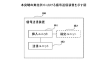
図1は、本発明の実施例1における信号送信装置を示す図である。図1に示すように、該装置100は、次のようなものを含む。
FIG. 1 is a diagram illustrating a signal transmission device according to the first embodiment of the present invention. As shown in FIG. 1, the
插入ユニット101:データ変調信号に少なくとも1つの振幅可変な位相変調信号を挿入し、これにより、受信端でキャリア位相復元を行い;
送信ユニット102:該データ変調信号に該位相変調信号を挿入した後に形成された送信信号を送信する。
Insertion unit 101: inserting at least one phase-modulated signal with variable amplitude into the data-modulated signal, thereby performing carrier phase recovery at the receiving end;
Transmission unit 102: transmits a transmission signal formed after the phase modulation signal is inserted into the data modulation signal.
本実施例から分かるように、データ変調信号に振幅可変な位相変調信号を挿入することで、受信端で該位相変調信号に基づいて受信信号のキャリア位相復元を行う時に、各種変調フォーマットの通信システムに適用することができ、従来の通信システムとの互換性を有し、且つ比較的低い計算複雑度を有する。また、插入される位相変調信号が振幅可変なものであるので、データ変調信号に該位相変調信号を柔軟に設定することができ、これにより、冗長を低減することができ、且つシステム容量への影響が比較的に小さい。 As can be seen from the present embodiment, a communication system of various modulation formats is used when carrier phase restoration of a received signal is performed based on the phase modulated signal at the receiving end by inserting a phase modulated signal with variable amplitude into the data modulated signal. It is compatible with conventional communication systems and has a relatively low computational complexity. In addition, since the phase modulation signal to be inserted has a variable amplitude, the phase modulation signal can be flexibly set to the data modulation signal, thereby reducing the redundancy and reducing the system capacity. The impact is relatively small.
本実施例では、插入ユニット101は、データ変調信号に少なくとも1つの振幅可変な位相変調信号を挿入し、そのうち、該データ変調信号は、任意フォーマットのデータ変調信号、例えば、非定モジュラス変調の32QAM、64QAM信号であっても良い。
In this embodiment, the
本実施例では、該データ変調信号は、複数種変調フォーマットの信号を含んでも良く、例えば、該データ変調信号は、16QAM、32QAM、64QAMなどの複数種変調フォーマットの信号を含む。また、該データ変調信号は、さらに、所定の訓練シーケンスを含んでも良く、又は、訓練シーケンスを含まなくても良い。 In this embodiment, the data modulation signal may include a signal of a plurality of types of modulation formats. For example, the data modulation signal includes a signal of a plurality of types of modulation formats such as 16QAM, 32QAM, and 64QAM. The data modulation signal may further include a predetermined training sequence or may not include a training sequence.
本実施例では、插入される位相変調信号は、1つであっても良く、複数であっても良く、その数量は、実際のニーズに応じて設定されても良い。なお、本実施例では、複数の位相変調信号を挿入するケースを例として説明する。 In the present embodiment, the phase modulation signal to be inserted may be one or plural, and the number thereof may be set according to actual needs. In this embodiment, a case where a plurality of phase modulation signals are inserted will be described as an example.
本実施例では、データ変調信号に位相変調信号を挿入する位置及び方式は、実際のニーズに応じて設定されても良く、例えば、插入ユニット101は、時間領域上で連続して又は所定間隔でデータ変調信号に該位相変調信号を挿入しても良い。
In the present embodiment, the position and method of inserting the phase modulation signal into the data modulation signal may be set according to actual needs. For example, the
図2は、本発明の実施例1における送信信号のフレーム構造を示す図である。図2に示すように、データAは、データ変調信号を表し、データBは、位相変調信号を表し、時間領域上では、所定間隔で複数の位相変調信号を挿入する。 FIG. 2 is a diagram illustrating a frame structure of a transmission signal according to the first embodiment of the present invention. As shown in FIG. 2, data A represents a data modulation signal, data B represents a phase modulation signal, and a plurality of phase modulation signals are inserted at predetermined intervals on the time domain.
図3は、本発明の実施例1における送信信号のフレーム構造を示す他の図である。図3に示すように、データAは、データ変調信号を表し、データBは、位相変調信号を表し、時間領域上では、連続して複数の位相変調信号を挿入する。 FIG. 3 is another diagram showing a frame structure of a transmission signal in Embodiment 1 of the present invention. As shown in FIG. 3, data A represents a data modulation signal, data B represents a phase modulation signal, and a plurality of phase modulation signals are continuously inserted in the time domain.
本実施例では、図2及び図3中でのデータA及びデータBの長さは、実際のニーズに応じて任意設定されても良く、また、データB、即ち、位相変調信号は、送信信号中で占める比は、可変なものであり、それは、実際のニーズに応じて構成されても良い。 In the present embodiment, the lengths of data A and data B in FIGS. 2 and 3 may be arbitrarily set according to actual needs, and data B, that is, the phase modulation signal, is a transmission signal. The ratio occupied in it is variable and it may be configured according to actual needs.
本実施例では、該位相変調信号の振幅は、可変なものであり、例えば、データ変調信号中で、該位相変調信号は、振幅が異なる複数の位相変調信号を含んでも良く、振幅が同じである複数の位相変調信号、例えば、QPSK信号を含んでも良い。 In this embodiment, the amplitude of the phase modulation signal is variable. For example, in the data modulation signal, the phase modulation signal may include a plurality of phase modulation signals having different amplitudes, and the amplitude is the same. A plurality of phase modulation signals, for example, QPSK signals may be included.
本実施例では、該位相変調信号の数量が複数である時に、任意の2つの位相変調信号の間の位相差は、(mπ)/nと設定されても良く、m、nは、ゼロでない整数である。例えば、周波数上で隣接する2つの位相変調信号の間の位相差は、π/2と設定することができる。 In the present embodiment, when the number of the phase modulation signals is plural, the phase difference between any two phase modulation signals may be set to (mπ) / n, and m and n are not zero. It is an integer. For example, the phase difference between two phase modulation signals adjacent in frequency can be set to π / 2.
本実施例では、插入される位相変調信号は、データ変調信号の信号空間ダイヤグラム(constellation diagram(信号星座図とも言う))上での所定の星座点と重なり合っても良い。このように、従来送信機のハードウェアにより実現することができるため、従来システムとの互換性をより一層向上させ、計算複雑度をより一層低減することができる。 In this embodiment, the inserted phase modulation signal may overlap with a predetermined constellation point on the signal space diagram (constellation diagram) of the data modulation signal. Thus, since it can be realized by the hardware of the conventional transmitter, compatibility with the conventional system can be further improved, and the computational complexity can be further reduced.
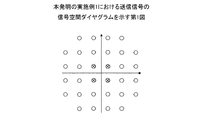
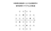
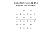
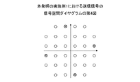
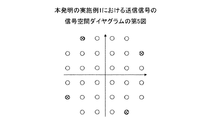
以下、振幅が同じである複数の位相変調信号、即ち、QPSK信号を例として、位相変調信号に挿入されるデータ変調信号の構造について例示的に説明する。 Hereinafter, the structure of the data modulation signal inserted into the phase modulation signal will be exemplarily described by taking a plurality of phase modulation signals having the same amplitude, that is, QPSK signals as an example.
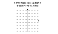
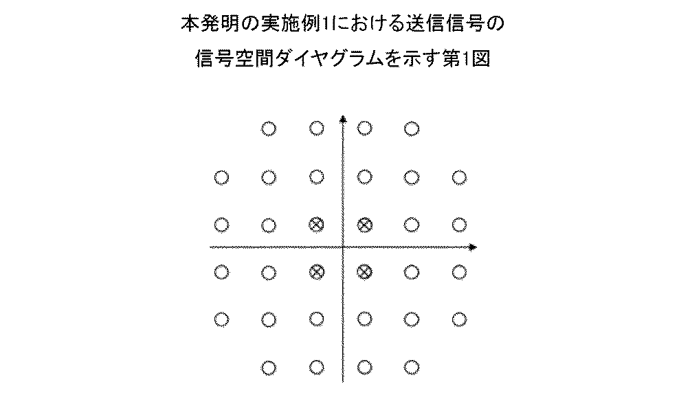
図4は、本発明の実施例1における送信信号の信号空間ダイヤグラムを示す第1図である。図5は、本発明の実施例1における送信信号の信号空間ダイヤグラムを示す第2図である。図6は、本発明の実施例1における送信信号の信号空間ダイヤグラムを示す第3図である。図7は、本発明の実施例1における送信信号の信号空間ダイヤグラムを示す第4図である。図8は、本発明の実施例1における送信信号の信号空間ダイヤグラムを示す第5図である。図4〜図8に示すように、○は、データ変調信号を表し、
(外1)
![]()
(Outside 1)
![]()
図4に示すように、插入される位相変調信号は、32QAM信号の信号空間ダイヤグラムの最内側の円形上での星座点に位置し、図5に示すように、插入される位相変調信号は、32QAM信号の信号空間ダイヤグラムの内から2番目の円形上での星座点に位置し、図6に示すように、插入される位相変調信号は、32QAM信号の信号空間ダイヤグラムの内から3番目の円形上での星座点に位置し、図7に示すように、插入される位相変調信号は、32QAM信号の信号空間ダイヤグラムの内から4番目の円形上での星座点に位置し、図8に示すように、插入される位相変調信号は、32QAM信号の信号空間ダイヤグラムの最外側の円形上での星座点に位置する。そのうち、隣接する位相変調信号の位相差は、π/2である。 As shown in FIG. 4, the inserted phase modulation signal is located at the constellation point on the innermost circle in the signal space diagram of the 32QAM signal, and as shown in FIG. 5, the inserted phase modulation signal is Positioned at the constellation point on the second circle in the signal space diagram of the 32QAM signal, as shown in Fig. 6, the phase-modulated signal inserted is the third circle in the signal space diagram of the 32QAM signal. As shown in Fig. 7, the phase modulation signal inserted is located at the constellation point on the fourth circle in the signal space diagram of the 32QAM signal, as shown in Fig. 7 and shown in Fig. 8. Thus, the inserted phase modulation signal is located at the constellation point on the outermost circle of the signal space diagram of the 32QAM signal. Among them, the phase difference between adjacent phase modulation signals is π / 2.
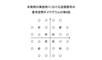
以下、振幅が異なる複数位相変調信号を例として、位相変調信号に挿入されるデータ変調信号の構造について例示的に説明する。 Hereinafter, the structure of the data modulation signal inserted into the phase modulation signal will be exemplarily described using a plurality of phase modulation signals having different amplitudes as an example.
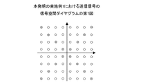
図9は、本発明の実施例1における送信信号の信号空間ダイヤグラムを示す第6図であり、図10は、本発明の実施例1における送信信号の信号空間ダイヤグラムを示す第7図であり、図11は、本発明の実施例1における送信信号の信号空間ダイヤグラムを示す第8図である。図9〜図11に示すように、○は、データ変調信号を示し、
(外2)
![]()
(Outside 2)
![]()
図9に示すように、データ変調信号は、32QAM信号であり、插入される位相変調信号は、32QAM信号の信号空間ダイヤグラムの最内側の円形及び内から3番目の円形上での星座点に位置し、即ち、32QAM信号空間ダイヤグラムのπ/4と3π/4の交差線上での星座点に位置し、図10に示すように、データ変調信号は、64QAM信号であり、插入される位相変調信号は、64QAM信号の信号空間ダイヤグラムの内からの1番目、3番目、5番目、7番目の円形上での星座点に位置し、即ち、64QAM信号空間ダイヤグラムのπ/4と3π/4の交差線上での星座点に位置し、図11に示すように、データ変調信号は、64QAM信号であり、插入される位相変調信号は、64QAM信号の信号空間ダイヤグラムの内からの1番目、3番目、5番目の円形上での星座点に位置し、即ち、64QAM信号空間ダイヤグラムのπ/4と3π/4の交差線上での星座点に位置する。 As shown in FIG. 9, the data modulation signal is a 32QAM signal, and the inserted phase modulation signal is located at the constellation point on the innermost circle and the third circle from the inside of the signal space diagram of the 32QAM signal. That is, it is located at the constellation point on the crossing line of π / 4 and 3π / 4 of the 32QAM signal space diagram, and as shown in FIG. 10, the data modulation signal is a 64QAM signal, and the phase modulation signal to be inserted Is located at the constellation points on the 1st, 3rd, 5th and 7th circles in the signal space diagram of the 64QAM signal, that is, the intersection of π / 4 and 3π / 4 of the 64QAM signal space diagram Located at the constellation point on the line, as shown in FIG. 11, the data modulation signal is a 64QAM signal, and the phase modulation signal to be inserted is the first, the third, from the signal space diagram of the 64QAM signal, Located at the constellation point on the fifth circle, i.e. π / 4 of the 64QAM signal space diagram Located in the constellation point at the intersection line of 3 [pi] / 4.
以上、本実例の位相変調信号の插入方式について例示的に説明したが、插入される位相変調信号は、データ変調信号の信号空間ダイヤグラム上での所定の星座点と重なり合わなくても良い。例えば、所定の星座点と一定角度を成す方式で位相変調信号を設置しても良い。 In the above, the insertion method of the phase modulation signal of this example has been exemplarily described. However, the phase modulation signal to be inserted may not overlap with a predetermined constellation point on the signal space diagram of the data modulation signal. For example, the phase modulation signal may be installed in a manner that forms a certain angle with a predetermined constellation point.
本実施例では、送信ユニット102は、該データ変調信号に該位相変調信号を挿入した後に形成された送信信号を送信し、それは、従来の信号送信方法を用いて送信を行っても良い。
In this embodiment, the
本実施例では、信号送信装置100は、さらに、次のようなものを含んでも良い。
In the present embodiment, the
確定ユニット103:位相変調信号の、データ変調信号の信号空間ダイヤグラム上での位置を確定し、これにより、該位相変調信号が該位置にあるときに、受信端でのビット誤り率が最も低くなるようにさせる。本実施例では、確定ユニット103は、オプションであり、図1中で点線で表される。
Determination unit 103: Determines the position of the phase modulation signal on the signal space diagram of the data modulation signal, so that the bit error rate at the receiving end is the lowest when the phase modulation signal is at the position. Let me do that. In this embodiment, the
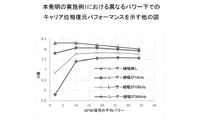
例えば、データ変調信号のフォーマットが32QAMであり、時間領域上でk個のデータ変調信号(QAM符号(symbol))毎に1つの位相変調信号を挿入し、kが正整数であるとする。そのうち、Q値を評価基準として、MATLABなどのソフトウェアに基づくシミュレーションにより、異なるQPSKパワーのキャリア位相復元パフォーマンスを取得しており、それは、受信端でのビット誤り率を表すことができ、また、異なるQPSKパワーは、QPSKが異なる插入位置を表す。 For example, it is assumed that the format of the data modulation signal is 32QAM, one phase modulation signal is inserted for every k data modulation signals (QAM code (symbol)) in the time domain, and k is a positive integer. Among them, the carrier phase restoration performance of different QPSK power has been obtained by simulation based on software such as MATLAB with Q value as evaluation criterion, which can represent bit error rate at receiving end and different The QPSK power represents the insertion position where QPSK is different.
図12は、本発明の実施例1における異なるパワー下でのキャリア位相復元パフォーマンスを示す図である。図12に示すように、kが8であり、即ち、時間領域上で8個のQAM符号毎に1つの位相変調信号を挿入し、信号空間ダイヤグラム中での最小単位が1と正規化されるとすると、32QAM信号の平均パワーは、20であり、図4〜図8に示す5種の位相変調信号(QPSK符号)のパワーは、順に、2、10、18、26、34であり、線幅無しの場合、最適のパワーの計算結果は、10であり、レーザーの線幅が10kHz、100kHz及び300kHzの場合、最適のQPSKパワーは、依然として10であり、即ち、図5に示すQPSKパワーが10である星座点の位置を、位相変調信号の信号空間ダイヤグラム上での位置と確定する。 FIG. 12 is a diagram showing carrier phase restoration performance under different powers in Example 1 of the present invention. As shown in FIG. 12, k is 8, that is, one phase modulation signal is inserted for every 8 QAM codes in the time domain, and the minimum unit in the signal space diagram is normalized to 1. Then, the average power of the 32QAM signal is 20, and the powers of the five types of phase modulation signals (QPSK codes) shown in FIGS. 4 to 8 are 2, 10, 18, 26, and 34 in order, In the case of no width, the calculation result of the optimum power is 10, and when the laser line width is 10 kHz, 100 kHz and 300 kHz, the optimum QPSK power is still 10, that is, the QPSK power shown in FIG. The position of the constellation point that is 10 is determined as the position on the signal space diagram of the phase modulation signal.
図13は、本発明の実施例1における異なるパワー下でのキャリア位相復元パフォーマンスを示す他の図である。図13に示すように、kが16であり、即ち、16個のQAM符号毎に1つの位相変調信号を挿入し、信号空間ダイヤグラム中での最小単位が1と正規化されるとすると、32QAM信号の平均パワーは20であり、図4〜図8に示す5種の位相変調信号(QPSK符号)のパワーは、順に、2、10、18、26、34であり、線幅なしの場合、最適のパワーの計算結果は、10であり、レーザーの線幅が10kHz、100kHz及び300kHzの場合、最適のQPSKパワーは、それぞれ、10、18及び26であり、即ち、図4、図5又は図6にそれぞれ示すQPSKパワーが10、18又は26である星座点の位置を、位相変調信号の信号空間ダイヤグラム上での位置と確定する。 FIG. 13 is another diagram showing the carrier phase restoration performance under different power in the first embodiment of the present invention. As shown in FIG. 13, if k is 16, that is, if one phase modulation signal is inserted for every 16 QAM codes, and the minimum unit in the signal space diagram is normalized to 1, 32QAM The average power of the signal is 20, and the powers of the five types of phase modulation signals (QPSK codes) shown in FIGS. 4 to 8 are 2, 10, 18, 26, and 34 in this order. The optimal power calculation result is 10, and when the laser line width is 10 kHz, 100 kHz and 300 kHz, the optimal QPSK power is 10, 18 and 26, respectively, ie, FIG. 4, FIG. 5 or FIG. The position of the constellation point where the QPSK power shown in 6 is 10, 18 or 26 is determined as the position on the signal space diagram of the phase modulation signal.
本実施例から分かるように、データ変調信号に振幅可変な位相変調信号を挿入することで、受信端で該位相変調信号に基づいて受信信号のキャリア位相復元を行う時に、各種変調フォーマットの通信システムに適用することができ、従来の通信システムとの互換性を有し、且つ比較的低い計算複雑度を有する。また、插入される位相変調信号が振幅可変なものであるので、データ変調信号に該位相変調信号を柔軟に配置することができ、これにより、冗長を低減することができ、且つシステム容量への影響が比較的小さい。 As can be seen from the present embodiment, a communication system of various modulation formats is used when carrier phase restoration of a received signal is performed based on the phase modulated signal at the receiving end by inserting a phase modulated signal with variable amplitude into the data modulated signal. It is compatible with conventional communication systems and has a relatively low computational complexity. In addition, since the phase modulation signal to be inserted has a variable amplitude, the phase modulation signal can be flexibly arranged in the data modulation signal, thereby reducing redundancy and reducing the system capacity. The impact is relatively small.
また、插入される位相変調信号は、データ変調信号の信号空間ダイヤグラム上での所定星座点と重なり合っても良い。このように、従来送信機のハードウェアにより実現することができるため、従来システムとの互換性をより一層向上させ、計算複雑度をより一層低減することができる。 Further, the inserted phase modulation signal may overlap with a predetermined constellation point on the signal space diagram of the data modulation signal. Thus, since it can be realized by the hardware of the conventional transmitter, compatibility with the conventional system can be further improved, and the computational complexity can be further reduced.
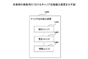
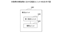
本発明の実施例は、さらに、キャリア位相復元装置を提供する。図14は、本発明の実施例2におけるキャリア位相復元装置を示す図である。図14に示すように、該装置1400は、次のようなものを含む。
The embodiment of the present invention further provides a carrier phase restoration apparatus. FIG. 14 is a diagram illustrating a carrier phase restoration apparatus according to
抽出ユニット1401:受信信号中での位相変調信号を抽出し、そのうち、該位相変調信号は、送信端で送信されるデータ変調信号に插入された振幅可変な位相変調信号であり;
推定ユニット1402:受信信号中での位相変調信号に基づいて、受信信号の位相ノイズを推定し;
補償ユニット1403:受信信号の位相ノイズに基づいて、受信信号に対して位相補償を行う。
Extraction unit 1401: Extracts a phase modulation signal from the received signal, of which the phase modulation signal is a phase modulation signal with variable amplitude inserted into the data modulation signal transmitted at the transmission end;
Estimating unit 1402: estimating phase noise of the received signal based on the phase modulation signal in the received signal;
Compensation unit 1403: Performs phase compensation on the received signal based on the phase noise of the received signal.
本実施例から分かるように、データ変調信号に振幅可変な位相変調信号を挿入することで、受信端で該位相変調信号に基づいて受信信号のキャリア位相復元を行う時に、各種変調フォーマットの通信システムに適用することができ、従来の通信システムとの互換性を有し、且つ比較的低い計算複雑度を有する。また、插入される位相変調信号が振幅可変なものであるので、データ変調信号に該位相変調信号を柔軟に構成することができ、これにより、冗長を低減することができ、且つシステム容量への影響が比較的小さい。 As can be seen from the present embodiment, a communication system of various modulation formats is used when carrier phase restoration of a received signal is performed based on the phase modulated signal at the receiving end by inserting a phase modulated signal with variable amplitude into the data modulated signal. It is compatible with conventional communication systems and has a relatively low computational complexity. In addition, since the phase modulation signal to be inserted has a variable amplitude, the phase modulation signal can be flexibly configured in the data modulation signal, thereby reducing redundancy and reducing the system capacity. The impact is relatively small.
本実施例では、抽出ユニット1401は、受信信号中での位相変調信号を抽出し、該受信信号は、実施例1に記載の信号送信装置が送信した信号が伝送リンクを経た後に、受信端で受信された信号である。
In the present embodiment, the
本実施例では、抽出ユニット1401が位相変調信号を抽出する方法は、従来方法を採用しても良い。
In the present embodiment, a conventional method may be adopted as the method by which the
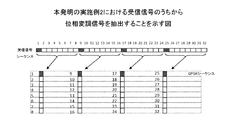
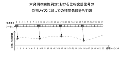
例えば、図15は、本発明の実施例2における受信信号から位相変調信号を抽出することを示す図である。図15に示すように、時間領域上で各8個の受信符号に1つの位相変調信号(例えば、QPSK符号)、及び、7個の連続したデータ変調信号(例えば、QAM符号)を有するとする。QPSK符号とQAM符号のモジュラス値の平均値が異なるため、所定期間内でのモジュラス値の平均値を計算することにより、現在の符号がQPSK符号又はQAM符号であるかを直接判断することができる。 For example, FIG. 15 is a diagram illustrating extraction of a phase modulation signal from a reception signal according to the second embodiment of the present invention. As shown in FIG. 15, it is assumed that one received phase modulation signal (for example, QPSK code) and seven continuous data modulation signals (for example, QAM code) are included in each of eight received codes in the time domain. . Since the average value of the modulus values of the QPSK code and the QAM code is different, it is possible to directly determine whether the current code is a QPSK code or a QAM code by calculating the average value of the modulus values within a predetermined period. .
本実施例では、抽出ユニット1401が受信信号中での位相変調信号を抽出した後に、推定ユニット1402は、受信信号中での位相変調信号に基づいて、受信信号の位相ノイズを推定する。
In this embodiment, after the
以下、本実施例における推定ユニット1402の構造及び受信信号の位相ノイズの推定方法について例示的に説明する。
Hereinafter, the structure of the
図16は、本発明の実施例2における推定ユニット1402を示す図である。図16に示すように、推定ユニット1402は、次のようなものを含む。
FIG. 16 is a diagram illustrating the
第一推定ユニット1601:該位相変調信号の位相ノイズを推定し;
補間ユニット1602:該位相変調信号の位相ノイズに対して補間処理を行い、受信信号の位相ノイズを得る。
First estimation unit 1601: estimating phase noise of the phase modulation signal;
Interpolation unit 1602: Interpolates the phase noise of the phase modulation signal to obtain the phase noise of the received signal.
本実施例では、第一推定ユニット1601は、従来方法により該位相変調信号の位相ノイズを推定しても良い。例えば、ビタビ(Viterbi-Viterbi)アルゴリズムを用いて位相ノイズ推定を行う。
In the present embodiment, the
受信信号が次の式(1)で表されるとし、即ち、
I=A・exp(j(θsignal+θnoise)) (1)
である
そのうち、Aは、受信信号の振幅を表し、θsignal及びθnoiseは、それぞれ、変調位相及びノイズ位相を表す。
Assume that the received signal is expressed by the following equation (1):
I = A ・ exp (j (θ signal + θ noise )) (1)
Where A represents the amplitude of the received signal, and θ signal and θ noise represent the modulation phase and the noise phase, respectively.
式(1)に対して4乗の演算を行った後に、次の式(2)を得ることができ、即ち、
I4=A4・exp(j(4θsignal+4θnoise)) (2)
である。
After performing a fourth power operation on equation (1), the following equation (2) can be obtained:
I 4 = A 4・ exp (j (4θ signal + 4θ noise )) (2)
It is.
図4〜図11に示す位相変調信号について、隣接する位相変調信号が位置する星座点の間にπ/2の位相間隔を有し、変調位相θsignal=n・π/4であり、n=1、3、5、7であり、この場合、exp(j4θsignal)=-1であり、変調信号の位相情報を除去することができる。 For the phase modulation signals shown in FIGS. 4 to 11, there is a phase interval of π / 2 between the constellation points where the adjacent phase modulation signals are located, the modulation phase θ signal = n · π / 4, and n = 1, 3, 5, and 7. In this case, exp (j4θ signal ) = − 1, and the phase information of the modulation signal can be removed.
長さがNであるデータブロックの平均位相ノイズを計算することにより、第i個目の符号の位相ノイズの推定値φiを得ることができ、それは、次の式(3)で表すことができる。
そのうち、φiは、第i個目の符号の位相ノイズ推定値を表し、arg()は、角度を取る操作を表し、ceil()は、CEILING関数(切り上げ)を表し、floor()は、FLOOR関数(切り捨て)を表す。 Of these, φ i represents the phase noise estimate of the i-th code, arg () represents the operation of taking an angle, ceil () represents the CEILING function (rounded up), and floor () Represents the FLOOR function (truncated).
本実施例では、図4、図6、図9、図10及び図11中での位相変調信号について、上述のViterbi-Viterbiアルゴリズムを直接用いて位相ノイズを推定しても良く、図5、図7及び図8中での3種の単一振幅位相変調信号について、Viterbi-Viterbiアルゴリズムを用いる前に、入力信号Iを、対応する角度回転する必要があり、回転角度は、それぞれ、arctan(1/3)、arctan(1/5)及びarctan(3/5)である。 In the present embodiment, phase noise may be estimated directly using the above-mentioned Viterbi-Viterbi algorithm for the phase modulation signals in FIGS. 4, 6, 9, 10 and 11. For the three single amplitude phase modulated signals in FIGS. 7 and 8, before using the Viterbi-Viterbi algorithm, the input signal I needs to be rotated by a corresponding angle, the rotation angle being arctan (1 / 3), arctan (1/5) and arctan (3/5).
本実施例では、補間ユニット1602は、従来方法により該位相変調信号の位相ノイズに対して補間処理を行っても良く、例えば、Constant Interpolation法、線形補間法及Cubic Spline Interpolation法などである。
In this embodiment, the
図17は、本発明の実施例2における対位相変調信号の位相ノイズに対しての補間処理を示す図である。図17に示すように、時間領域上で各8個の受信符号に1つの位相変調信号(例えば、QPSK符号)、及び、7個の連続したデータ変調信号(例えば、QAM符号)を有し、符号位置1、9、17、25の所がQPSK符号であることが既知とすると、計算された対応する4個の位相ノイズ推定値に基づいて、補間計算により4組のQAM符号の位相推定値を取得することで、受信信号の位相ノイズ推定を完成することができる。 FIG. 17 is a diagram illustrating an interpolation process for phase noise of the anti-phase modulation signal according to the second embodiment of the present invention. As shown in FIG. 17, each time reception code has one phase modulation signal (for example, QPSK code) and seven continuous data modulation signals (for example, QAM code) in the time domain, Assuming that code positions 1, 9, 17, and 25 are QPSK codes, based on the calculated four corresponding phase noise estimates, four sets of QAM code phase estimates are calculated by interpolation. Is obtained, phase noise estimation of the received signal can be completed.
本実施例では、受信信号の位相ノイズを推定した後に、補償ユニット1403は、受信信号の位相ノイズに基づいて、受信信号に対して位相補償を行う。
In this embodiment, after estimating the phase noise of the received signal, the
本実施例から分かるように、データ変調信号に振幅可変な位相変調信号を挿入することで、受信端で該位相変調信号に基づいて受信信号のキャリア位相復元を行う時に、各種変調フォーマットの通信システムに適用することができ、従来の通信システムとの互換性を有し、且つ比較的小さい計算複雑度を有する。また、插入される位相変調信号が振幅可変なものであるので、データ変調信号に柔軟に該位相変調信号を構成することができ、これにより、冗長を低減することができ、且つシステム容量への影響が比較的小さい。 As can be seen from the present embodiment, a communication system of various modulation formats is used when carrier phase restoration of a received signal is performed based on the phase modulated signal at the receiving end by inserting a phase modulated signal with variable amplitude into the data modulated signal. And is compatible with conventional communication systems and has a relatively low computational complexity. In addition, since the phase modulation signal to be inserted has a variable amplitude, the data modulation signal can be flexibly configured with the phase modulation signal, thereby reducing redundancy and reducing the system capacity. The impact is relatively small.
本発明の実施例は、さらに、送信機を提供する。図18は、本発明の実施例3における送信機を示す図である。図18に示すように、該送信機1800は、信号送信装置1801を含み、該信号送信装置1801の構造及び機能は、実施例1と同じであるため、ここの詳しい記載が省略される。
Embodiments of the present invention further provide a transmitter. FIG. 18 is a diagram illustrating the transmitter according to the third embodiment of the present invention. As shown in FIG. 18, the
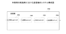
図19は、本発明の実施例3における送信機のシステム構成図である。図19に示すように、送信機1900は、插入ユニット1901、送信ユニット1902、DACユニット1903及び光変調器ユニット1904を含む。
FIG. 19 is a system configuration diagram of a transmitter in
そのうち、插入ユニット1901は、データ変調信号に少なくとも1つの振幅可変な位相変調信号を、受信端でキャリア位相復元を行うために挿入し;送信ユニット1902は、データ変調信号に位相変調信号が挿入された後に形成された送信信号を送信し、該送信信号は、デジタル信号であり、插入ユニット1901及び送信ユニット1902の構造及び機能は、実施例1と同じであるため、ここでの詳しい説明が省略され;DACユニット1903は、該デジタル信号に対してDACを行い;光変調器ユニット1904は、該DACユニット1903の変換後の信号を変調信号として光信号に対して変調を行う。
Among them, the
本実施例から分かるように、データ変調信号に振幅可変な位相変調信号を挿入することで、受信端で該位相変調信号に基づいて受信信号のキャリア位相復元を行う時に、各種変調フォーマットの通信システムに適用することができ、従来の通信システムとの互換性を有し、且つ比較的低い計算複雑度を有する。また、插入される位相変調信号が振幅可変なものであるので、データ変調信号に該位相変調信号を柔軟に配置することができ、これにより、冗長を低減することができ、且つシステム容量への影響が比較的小さい。 As can be seen from the present embodiment, a communication system of various modulation formats is used when carrier phase restoration of a received signal is performed based on the phase modulated signal at the receiving end by inserting a phase modulated signal with variable amplitude into the data modulated signal. It is compatible with conventional communication systems and has a relatively low computational complexity. In addition, since the phase modulation signal to be inserted has a variable amplitude, the phase modulation signal can be flexibly arranged in the data modulation signal, thereby reducing redundancy and reducing the system capacity. The impact is relatively small.
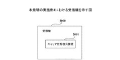
本発明の実施例は、さらに、受信機を提供する。図20は、本発明の実施例4における受信機を示す図である。図20に示すように、該受信機2000は、キャリア位相復元装置2001を含み、該キャリア位相復元装置2001の構造及び機能は、実施例2と同じであるため、ここでの詳しい説明が省略される。
Embodiments of the present invention further provide a receiver. FIG. 20 is a diagram illustrating the receiver according to the fourth embodiment of the present invention. As shown in FIG. 20, the
図21は、本発明の実施例4における受信機のシステム構成図である。図21に示すように、受信機2100は、次のようなものを含む。
FIG. 21 is a system configuration diagram of a receiver according to Embodiment 4 of the present invention. As shown in FIG. 21, the
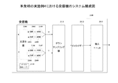
フロントエンド:入力された光信号を2つの偏光状態のベースバンド信号を変換し、本実施例では、該2つの偏光状態は、H偏光状態及びV偏光状態を含んでも良い。 Front end: An input optical signal is converted into a baseband signal in two polarization states, and in this embodiment, the two polarization states may include an H polarization state and a V polarization state.
図21に示すように、該フロントエンドは、ローカル発振レーザー2110、光混合器(Optical 90deg hybrid)2101、光電検出器(O/E)2102、2104、2106、2108、アナログデジタル変換器(ADC)2103、2105、2107、2109、ダウンサンプリング器2111、イコライザー2112及び復元ユニット2113を含み、そのうち、復元ユニット2113は、実施例2に記載のキャリア位相復元装置と同じ構造及び機能を有しても良いため、ここでの詳しい説明が省略され;ローカル発振レーザー2110は、ロカール光源を提供し、光信号は、光混合器(Optical 90deg hybrid)2101、光電検出器(O/E)2102、2104、及びアナログデジタル変換器(ADC)2103、2105を経た後に、H偏光状態のベースバンド信号に変換され;また、該光信号は、光混合器(Optical 90deg hybrid)2101、光電検出器(O/E)2106、2108、及びアナログデジタル変換器(ADC)2107、2109を経た後に、V偏光状態のベースバンド信号に変換され、その具体的なプロセスは、従来技術に類似したため、ここでの詳細な記載が省略される。
As shown in FIG. 21, the front end includes a local oscillation laser 2110, an optical mixer (Optical 90deg hybrid) 2101, photoelectric detectors (O / E) 2102, 2104, 2106, 2108, and an analog-digital converter (ADC). 2103, 2105, 2107, 2109,
本実施例から分かるように、データ変調信号に振幅可変な位相変調信号を挿入することで、受信端で該位相変調信号に基づいて受信信号のキャリア位相復元を行う時に、各種変調フォーマットの通信システムに適用することができ、従来の通信システムとの互換性を有し、且つ比較的低い計算複雑度を有する。また、插入された位相変調信号が振幅可変なものであるので、データ変調信号に該位相変調信号を柔軟に設定することができ、これにより、冗長を低減することができ、且つシステム容量への影響が比較的小さい。 As can be seen from the present embodiment, a communication system of various modulation formats is used when carrier phase restoration of a received signal is performed based on the phase modulated signal at the receiving end by inserting a phase modulated signal with variable amplitude into the data modulated signal. It is compatible with conventional communication systems and has a relatively low computational complexity. Further, since the inserted phase modulation signal has a variable amplitude, the phase modulation signal can be flexibly set to the data modulation signal, thereby reducing the redundancy and reducing the system capacity. The impact is relatively small.
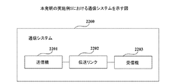
本発明の実施例は、さらに、通信システムを提供する。図22は、本発明の実施例5における通信システムを示す図である。図22に示すように、通信システム2200は、送信機2201、伝送リンク2202及び受信機2203を含み、そのうち、送信機2201の構造及び機能は、実施例3と同じであり、受信機2203の構造及び機能は、実施例4と同じであるため、ここでは、その詳しい説明を省略する。伝送リンク2202は、従来伝送リンクの構造及び機能を有しても良く、本実施例は、伝送リンクの構造及び機能について限定しない。
Embodiments of the present invention further provide a communication system. FIG. 22 is a diagram illustrating the communication system according to the fifth embodiment of the present invention. As shown in FIG. 22, the
本実施例から分かるように、データ変調信号に振幅可変な位相変調信号を挿入することで、受信端で該位相変調信号に基づいて受信信号のキャリア位相復元を行う時に、各種変調フォーマットの通信システムに適用することができ、従来の通信システムとの互換性を有し、且つ比較的低い計算複雑度を有する。また、插入される位相変調信号が振幅可変なものであるので、データ変調信号に該位相変調信号を柔軟に配置することができ、これにより、冗長を低減することができ、且つシステム容量への影響が比較的小さい。 As can be seen from the present embodiment, a communication system of various modulation formats is used when carrier phase restoration of a received signal is performed based on the phase modulated signal at the receiving end by inserting a phase modulated signal with variable amplitude into the data modulated signal. It is compatible with conventional communication systems and has a relatively low computational complexity. In addition, since the phase modulation signal to be inserted has a variable amplitude, the phase modulation signal can be flexibly arranged in the data modulation signal, thereby reducing redundancy and reducing the system capacity. The impact is relatively small.
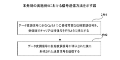
本発明の実施例は、さらに、信号送信方法を提供し、該方法は、実施例1における信号送信装置に対応する。図23は、本実施例6における信号送信方法を示す図である。図23に示すように、該方法は、次のようステップを含む。 The embodiment of the present invention further provides a signal transmission method, which corresponds to the signal transmission apparatus in the first embodiment. FIG. 23 is a diagram illustrating a signal transmission method according to the sixth embodiment. As shown in FIG. 23, the method includes the following steps.
ステップ2301:データ変調信号に少なくとも1つの振幅可変な位相変調信号を、受信端でキャリア位相復元を行うように挿入し;
ステップ2302:データ変調信号に位相変調信号が挿入された後に形成された送信信号を送信する。
Step 2301: Insert at least one phase-modulated signal with variable amplitude into the data-modulated signal so as to perform carrier phase recovery at the receiving end;
Step 2302: Transmit the transmission signal formed after the phase modulation signal is inserted into the data modulation signal.
本実施例では、位相変調信号の挿入方法及び送信信号の送信方法は、実施例1と同じであるため、ここでは、その詳しい説明を省略する。 In the present embodiment, the phase modulation signal insertion method and the transmission signal transmission method are the same as those in the first embodiment, and thus detailed description thereof is omitted here.
本実施例から分かるように、データ変調信号に振幅可変な位相変調信号を挿入することで、受信端で該位相変調信号に基づいて受信信号のキャリア位相復元を行う時に、各種変調フォーマットの通信システムに適用することができ、従来の通信システムとの互換性を有し、且つ比較的低い算複雑度を有する。また、插入される位相変調信号が振幅可変なものであるので、データ変調信号に該位相変調信号を柔軟に配置することができ、これにより、冗長を低減することができ、且つシステム容量への影響が比較的小さい。 As can be seen from the present embodiment, a communication system of various modulation formats is used when carrier phase restoration of a received signal is performed based on the phase modulated signal at the receiving end by inserting a phase modulated signal with variable amplitude into the data modulated signal. It is compatible with conventional communication systems and has a relatively low computational complexity. In addition, since the phase modulation signal to be inserted has a variable amplitude, the phase modulation signal can be flexibly arranged in the data modulation signal, thereby reducing redundancy and reducing the system capacity. The impact is relatively small.
本発明の実施例は、さらに、キャリア位相復元方法を提供し、該方法は、実施例2のキャリア位相復元装置に対応する。図24は、本実施例7におけるキャリア位相復元方法を示す図である。図24に示すように、該方法は、次のようなステップを含む。 The embodiment of the present invention further provides a carrier phase restoration method, which corresponds to the carrier phase restoration apparatus of the second embodiment. FIG. 24 is a diagram illustrating the carrier phase restoration method according to the seventh embodiment. As shown in FIG. 24, the method includes the following steps.
ステップ2401:受信信号中での位相変調信号を抽出し、そのうち、該位相変調信号は、送信端で送信されるデータ変調信号に插入された振幅可変な位相変調信号であり;
ステップ2402:受信信号中での位相変調信号に基づいて、受信信号の位相ノイズを推定し;
ステップ2403:受信信号の位相ノイズに基づいて、受信信号に対して位相補償を行う。
Step 2401: Extracting a phase modulation signal from a received signal, wherein the phase modulation signal is a phase modulation signal having a variable amplitude inserted into a data modulation signal transmitted at a transmission end;
Step 2402: estimating the phase noise of the received signal based on the phase modulated signal in the received signal;
Step 2403: Perform phase compensation on the received signal based on the phase noise of the received signal.
本実施例では、受信信号中での位相変調信号の抽出方法、受信信号中での位相変調信号に基づく受信信号の位相ノイズの推定方法、及び受信信号に対しての位相補償の補償方法は、実施例2と同じであるため、ここでは、その詳細な記載を省略する。 In this embodiment, a method for extracting a phase modulation signal in a reception signal, a method for estimating phase noise of a reception signal based on a phase modulation signal in a reception signal, and a compensation method for phase compensation for the reception signal are as follows: Since it is the same as the second embodiment, detailed description thereof is omitted here.
本実施例から分かるように、データ変調信号に振幅可変な位相変調信号を挿入することで、受信端で該位相変調信号に基づいて受信信号のキャリア位相復元を行う時に、各種変調フォーマットの通信システムに適用することができ、従来の通信システムとの互換性を有し、且つ比較的低い算複雑度を有する。また、插入される位相変調信号が振幅可変なものであるので、データ変調信号に該位相変調信号を柔軟に配置することができ、これにより、冗長を低減することができ、且つシステム容量への影響が比較的小さい。 As can be seen from the present embodiment, a communication system of various modulation formats is used when carrier phase restoration of a received signal is performed based on the phase modulated signal at the receiving end by inserting a phase modulated signal with variable amplitude into the data modulated signal. It is compatible with conventional communication systems and has a relatively low computational complexity. In addition, since the phase modulation signal to be inserted has a variable amplitude, the phase modulation signal can be flexibly arranged in the data modulation signal, thereby reducing redundancy and reducing the system capacity. The impact is relatively small.
本発明の実施例は、さらに、コンピュータ可読プログラムを提供し、そのうち、信号送信装置又は送信機中で前記プログラムを実行する時に、前記プログラムは、コンピュータに、前記信号送信装置又は送信機中で実施例6に記載の信号送信方法を実行させる。 Embodiments of the present invention further provide a computer readable program, wherein when the program is executed in a signal transmission device or transmitter, the program is implemented in a computer in the signal transmission device or transmitter. The signal transmission method described in Example 6 is executed.
本発明の実施例は、さらに、コンピュータ可読プログラムを提供し、そのうち、キャリア位相復元装置又は受信機中で前記プログラムを実行する時に、前記プログラムは、コンピュータに、前記キャリア位相復元装置又は受信機中で実施例7に記載のキャリア位相復元方法を実行させる。 Embodiments of the present invention further provide a computer readable program, of which, when executing the program in a carrier phase recovery apparatus or receiver, the program is stored in the computer in the carrier phase recovery apparatus or receiver. Then, the carrier phase restoration method described in the seventh embodiment is executed.
本発明の実施例は、さらに、コンピュータ可読プログラムを記憶した記憶媒体を提供し、そのうち、前記コンピュータ可読プログラムは、コンピュータに、信号送信装置又は送信機中で実施例6に記載の信号送信方法を実行させる。 The embodiment of the present invention further provides a storage medium storing a computer-readable program, and the computer-readable program is provided with the signal transmission method described in the sixth embodiment in a signal transmission apparatus or transmitter. Let it run.
本発明の実施例は、さらに、コンピュータ可読プログラムを記憶した記憶媒体を提供し、そのうち、前記コンピュータ可読プログラムは、コンピュータに、キャリア位相復元装置又は受信機中で実施例7に記載のキャリア位相復元方法を実行させる。 The embodiment of the present invention further provides a storage medium storing a computer readable program, wherein the computer readable program is stored in a computer in a carrier phase recovery apparatus or receiver in the carrier phase recovery described in the seventh embodiment. Let the method run.
本発明の実施例に記載の前記信号送信装置又は送信機中で実行される信号送信方法及びキャリア位相復元装置又は受信機中で実行されるキャリア位相復元方法は、ハードウェア、処理器により実行されるソフトウェアモジュール、又は両者の組み合わせにより実現されても良い。例えば、図1及び図14に示す機能ブロック図のうちの1つ又は複数及び/又は機能ブロック図の1つ又は複数の組み合わせは、コンピュータプログラムに関するソフトウェアモジュールに対応しても良く、各ハードウェアモジュールに対応しても良い。また、これらのソフトウェアモジュールは、それぞれ、図23及び図24に示す各ステップに対応しても良い。これらのハードウェアモジュールは、例えば、FPGA(field-programmable gate array)を用いて、これらのソフトウェアモジュールを固化して実現することができる。 The signal transmission method and carrier phase restoration method executed in the signal transmission device or transmitter according to the embodiment of the present invention are executed by hardware and a processor. It may be realized by a software module or a combination of both. For example, one or more of the functional block diagrams shown in FIGS. 1 and 14 and / or a combination of one or more functional block diagrams may correspond to software modules relating to a computer program, and each hardware module It may correspond to. These software modules may correspond to the steps shown in FIGS. 23 and 24, respectively. These hardware modules can be realized by solidifying these software modules using, for example, a field-programmable gate array (FPGA).
また、本発明の実施例による装置及び方法は、ソフトウェアにより実現されても良く、ハードウェアにより実現されてもよく、ハードウェア及びソフトウェアの組み合わせにより実現されても良い。また、本発明は、このようなコンピュータ可読プログラムにも関し、即ち、前記プログラムは、ロジック部品により実行される時に、前記ロジック部品に、上述の装置又は構成要素を実現させることができ、又は、前記ロジック部品に、上述の方法又はそのステップを実現させることができる。さらに、本発明は、上述のプログラムを記憶するための記憶媒体、例えば、ハードディスク、磁気ディスク、光ディスク、DVD、flashメモリなどにも関する。 Also, the apparatus and method according to the embodiments of the present invention may be realized by software, hardware, or a combination of hardware and software. The present invention also relates to such a computer-readable program, that is, when the program is executed by a logic component, the logic component can realize the above-described apparatus or component, or The above-described method or its steps can be realized in the logic component. Furthermore, the present invention also relates to a storage medium for storing the above-described program, for example, a hard disk, a magnetic disk, an optical disk, a DVD, a flash memory, and the like.
また、上述の実施例を含む実施形態に関し、更に以下の付記を開示する。 Moreover, the following additional remarks are disclosed regarding the embodiment including the above-described examples.
(付記1)
信号送信装置であって、
データ変調信号に少なくとも1つの振幅可変な位相変調信号を、受信端でキャリア位相復元を行うために挿入するための插入ユニット;及び
前記データ変調信号に前記位相変調信号が挿入された後に形成された送信信号を送信するための送信ユニットを含む、装置。
(Appendix 1)
A signal transmission device comprising:
An insertion unit for inserting at least one phase-modulated signal having a variable amplitude in the data modulation signal in order to perform carrier phase recovery at the receiving end; and formed after the phase modulation signal is inserted into the data modulation signal An apparatus comprising a transmission unit for transmitting a transmission signal.
(付記2)
付記1に記載の装置であって、
前記位相変調信号は、複数の振幅又は単一の振幅を有する、装置。
(Appendix 2)
The apparatus according to appendix 1, wherein
The apparatus, wherein the phase modulation signal has a plurality of amplitudes or a single amplitude.
(付記3)
付記1に記載の装置であって、
前記插入ユニットは、データ変調信号に少なくとも2つの前記位相変調信号を挿入し、
少なくとも2つの前記位相変調信号のうちの任意の2つの位相変調信号の間の位相差は、(mπ)/nであり、m及びnは、ゼロでない整数である、装置。
(Appendix 3)
The apparatus according to appendix 1, wherein
The insertion unit inserts at least two phase modulation signals into a data modulation signal;
The apparatus, wherein the phase difference between any two of the at least two phase modulation signals is (mπ) / n, and m and n are non-zero integers.
(付記4)
付記1に記載の装置であって、
前記位相変調信号及び前記データ変調信号の信号空間ダイヤグラム上での所定の星座点は、重なり合う、装置。
(Appendix 4)
The apparatus according to appendix 1, wherein
An apparatus, wherein predetermined constellation points on a signal space diagram of the phase modulation signal and the data modulation signal overlap.
(付記5)
付記1に記載の装置であって、
前記插入ユニットは、時間領域上で連続して又は所定間隔で前記データ変調信号に前記位相変調信号を挿入する、装置。
(Appendix 5)
The apparatus according to appendix 1, wherein
The insertion unit inserts the phase modulation signal into the data modulation signal continuously or at predetermined intervals in the time domain.
(付記6)
付記1に記載の装置であって、
前記位相変調信号が前記送信信号中で占める比は、可変なものである、装置。
(Appendix 6)
The apparatus according to appendix 1, wherein
The ratio that the phase modulation signal occupies in the transmission signal is variable.
(付記7)
付記1に記載の装置であって、さらに、
前記位相変調信号の、前記データ変調信号の信号空間ダイヤグラム上での位置を、前記位相変調信号が前記位置にある時に受信端でのビット誤り率が最も低くなるように確定するための確定ユニットを含む、装置。
(Appendix 7)
The apparatus according to appendix 1, further comprising:
A determination unit for determining the position of the phase modulation signal on the signal space diagram of the data modulation signal so that the bit error rate at the receiving end is lowest when the phase modulation signal is at the position; Including the device.
(付記8)
キャリア位相復元装置であって、
受信信号中での位相変調信号を抽出するための抽出ユニットであって、前記位相変調信号は、送信端で送信されるデータ変調信号に插入された振幅可変な位相変調信号である、抽出ユニット;
前記受信信号中での位相変調信号に基づいて、前記受信信号の位相ノイズを推定するための推定ユニット;及び
前記受信信号の位相ノイズに基づいて、前記受信信号に対して位相補償を行うための補償ユニットを含む、装置。
(Appendix 8)
A carrier phase recovery device,
An extraction unit for extracting a phase modulation signal in a received signal, wherein the phase modulation signal is a phase modulation signal having a variable amplitude inserted in a data modulation signal transmitted at a transmission end;
An estimation unit for estimating phase noise of the received signal based on a phase modulation signal in the received signal; and for performing phase compensation on the received signal based on phase noise of the received signal A device including a compensation unit.
(付記9)
付記8に記載の装置であって、
前記推定ユニットは、
前記位相変調信号の位相ノイズを推定するための第一推定ユニット;及び
前記位相変調信号の位相ノイズに対して補間処理を行い、前記受信信号の位相ノイズを得るための補間ユニットを含む、装置。
(Appendix 9)
The apparatus according to appendix 8, wherein
The estimation unit is:
An apparatus comprising: a first estimation unit for estimating phase noise of the phase modulation signal; and an interpolation unit for performing interpolation processing on the phase noise of the phase modulation signal to obtain phase noise of the reception signal.
(付記10)
送信機であって、前記送信機は、付記1〜7のうちの任意の一項に記載の信号送信装置を含む、送信機。
(Appendix 10)
It is a transmitter, Comprising: The said transmitter is a transmitter containing the signal transmitter of any one of the additional remarks 1-7.
(付記11)
受信機であって、前記受信機は、付記8又は9に記載のキャリア位相復元装置を含む、受信機。
(Appendix 11)
A receiver, wherein the receiver includes the carrier phase restoration device according to attachment 8 or 9.
(付記12)
通信システムであって、前記通信システムは、付記10に記載の送信機及び付記11に記載の受信機を含む、通信システム。
(Appendix 12)
A communication system, wherein the communication system includes a transmitter according to
(付記13)
信号送信方法であって、
データ変調信号に少なくとも1つの振幅可変な位相変調信号を、受信端でキャリア位相復元を行うために挿入し;及び
前記データ変調信号に前記位相変調信号が挿入された後に形成された送信信号を送信することを含む、方法。
(Appendix 13)
A signal transmission method,
Inserting at least one phase-modulated signal having a variable amplitude into the data modulation signal to perform carrier phase recovery at the receiving end; and transmitting a transmission signal formed after the phase modulation signal is inserted into the data modulation signal A method comprising:
(付記14)
付記13に記載の方法であって、
前記位相変調信号は、複数の振幅又は単一の振幅を有する、方法。
(Appendix 14)
The method according to
The method, wherein the phase modulation signal has a plurality of amplitudes or a single amplitude.
(付記15)
付記13に記載の方法であって、
前記データ変調信号に少なくとも1つの振幅可変な位相変調信号を挿入することは、
データ変調信号に少なくとも2つの前記位相変調信号を挿入し、そのうち、少なくとも2つの前記位相変調信号のうちの任意の2つの位相変調信号の間の位相差は、(mπ)/nであり、m及びnは、ゼロでない整数である、方法。
(Appendix 15)
The method according to
Inserting at least one variable amplitude phase modulation signal into the data modulation signal;
At least two phase modulation signals are inserted into a data modulation signal, of which the phase difference between any two of the at least two phase modulation signals is (mπ) / n, m And n is a non-zero integer.
(付記16)
付記13に記載の方法であって、
前記位相変調信号及び前記データ変調信号の信号空間ダイヤグラム上での所定の星座点は、重なり合う、方法。
(Appendix 16)
The method according to
A predetermined constellation point on a signal space diagram of the phase modulation signal and the data modulation signal overlaps.
(付記17)
付記13に記載の方法であって、
前記データ変調信号に少なくとも1つの振幅可変な位相変調信号を挿入することは、
時間領域上で連続して又は所定間隔で前記データ変調信号に前記位相変調信号を挿入することを含む、方法。
(Appendix 17)
The method according to
Inserting at least one variable amplitude phase modulation signal into the data modulation signal;
Inserting the phase modulation signal into the data modulation signal continuously in the time domain or at predetermined intervals.
(付記18)
付記13に記載の方法であって、
前記位相変調信号が前記送信信号中で占める比は、可変なものである、方法。
(Appendix 18)
The method according to
The ratio that the phase modulation signal occupies in the transmission signal is variable.
(付記19)
付記13に記載の方法であって、さらに、
前記位相変調信号の、前記データ変調信号の信号空間ダイヤグラム上での位置を、前記位相変調信号が前記位置にある時に受信端でのビット誤り率が最も低くなるように確定することを含む、方法。
(Appendix 19)
The method according to
Determining the position of the phase modulation signal on the signal space diagram of the data modulation signal so that the bit error rate at the receiving end is lowest when the phase modulation signal is at the position. .
(付記20)
キャリア位相復元方法であって、
受信信号中での位相変調信号を抽出し、そのうち、前記位相変調信号は、送信端で送信されるデータ変調信号に插入された振幅可変な位相変調信号であり;
前記受信信号中での位相変調信号に基づいて、前記受信信号の位相ノイズを推定し;及び
前記受信信号の位相ノイズに基づいて、前記受信信号に対して位相補償を行うことを含む、方法。
(Appendix 20)
A carrier phase recovery method comprising:
Extracting a phase-modulated signal from the received signal, wherein the phase-modulated signal is a phase-modulated signal having a variable amplitude inserted in a data-modulated signal transmitted at a transmitting end;
Estimating the phase noise of the received signal based on a phase modulation signal in the received signal; and performing phase compensation on the received signal based on the phase noise of the received signal.
(付記21)
付記20に記載の方法であって、
前記受信信号中での位相変調信号に基づいて、前記受信信号の位相ノイズを推定することは、
前記位相変調信号の位相ノイズを推定し;及び
前記位相変調信号の位相ノイズに対して補間処理を行い、前記受信信号の位相ノイズを得ることを含む、方法。
(Appendix 21)
The method according to
Estimating the phase noise of the received signal based on the phase modulation signal in the received signal,
Estimating the phase noise of the phase modulated signal; and interpolating the phase noise of the phase modulated signal to obtain the phase noise of the received signal.
以上、本発明の好ましい実施形態を説明したが、本発明はこの実施形態に限定されず、本発明の趣旨を離脱しない限り、本発明に対するあらゆる変更は本発明の技術的範囲に属する。
The preferred embodiment of the present invention has been described above, but the present invention is not limited to this embodiment, and all modifications to the present invention belong to the technical scope of the present invention unless departing from the spirit of the present invention.
Claims (10)
データ変調信号に少なくとも1つの振幅可変な位相変調信号を、受信端でキャリア位相復元を行うために挿入するための插入ユニット;及び
前記データ変調信号に前記位相変調信号が挿入された後に形成された送信信号を送信するための送信ユニットを含む、装置。 A signal transmission device comprising:
An insertion unit for inserting at least one phase-modulated signal having a variable amplitude in the data modulation signal in order to perform carrier phase recovery at the receiving end; and formed after the phase modulation signal is inserted into the data modulation signal An apparatus comprising a transmission unit for transmitting a transmission signal.
前記位相変調信号は、複数の振幅又は単一の振幅を有する、装置。 The apparatus of claim 1, wherein
The apparatus, wherein the phase modulation signal has a plurality of amplitudes or a single amplitude.
前記插入ユニットは、データ変調信号に少なくとも2つの前記位相変調信号を挿入し、
少なくとも2つの前記位相変調信号のうちの任意の2つの位相変調信号の間の位相差は、(mπ)/nであり、m及びnは、ゼロでない整数である、装置。 The apparatus of claim 1, wherein
The insertion unit inserts at least two phase modulation signals into a data modulation signal;
The apparatus, wherein the phase difference between any two of the at least two phase modulation signals is (mπ) / n, and m and n are non-zero integers.
前記位相変調信号と、前記データ変調信号の信号空間ダイヤグラム上での所定の星座点とは、重なり合う、装置。 The apparatus of claim 1, wherein
An apparatus in which the phase modulation signal and a predetermined constellation point on a signal space diagram of the data modulation signal overlap.
前記插入ユニットは、時間領域上で連続して又は所定間隔で前記データ変調信号に前記位相変調信号を挿入する、装置。 The apparatus of claim 1, wherein
The insertion unit inserts the phase modulation signal into the data modulation signal continuously or at predetermined intervals in the time domain.
前記位相変調信号が前記送信信号中で占める比は、可変なものである、装置。 The apparatus of claim 1, wherein
The ratio that the phase modulation signal occupies in the transmission signal is variable.
前記位相変調信号の、前記データ変調信号の信号空間ダイヤグラム上での位置を、前記位相変調信号が前記位置にある時に受信端でのビット誤り率が最も低くなるように確定するための確定ユニットをさらに含む、装置。 The apparatus of claim 1, wherein
A determination unit for determining the position of the phase modulation signal on the signal space diagram of the data modulation signal so that the bit error rate at the receiving end is lowest when the phase modulation signal is at the position; In addition, an apparatus.
受信信号中での位相変調信号を抽出するための抽出ユニットであって、前記位相変調信号は、送信端で送信されるデータ変調信号に插入された振幅可変な位相変調信号である、抽出ユニット;
前記受信信号中での位相変調信号に基づいて、前記受信信号の位相ノイズを推定するための推定ユニット;及び
前記受信信号の位相ノイズに基づいて、前記受信信号に対して位相補償を行うための補償ユニットを含む、装置。 A carrier phase recovery device,
An extraction unit for extracting a phase modulation signal in a received signal, wherein the phase modulation signal is a phase modulation signal having a variable amplitude inserted in a data modulation signal transmitted at a transmission end;
An estimation unit for estimating phase noise of the received signal based on a phase modulation signal in the received signal; and for performing phase compensation on the received signal based on phase noise of the received signal A device including a compensation unit.
前記推定ユニットは、
前記位相変調信号の位相ノイズを推定するための第一推定ユニット;及び
前記位相変調信号の位相ノイズに対して補間処理を行い、前記受信信号の位相ノイズを得るための補間ユニットを含む、装置。 The apparatus according to claim 8, wherein
The estimation unit is:
An apparatus comprising: a first estimation unit for estimating phase noise of the phase modulation signal; and an interpolation unit for performing interpolation processing on the phase noise of the phase modulation signal to obtain phase noise of the reception signal.
前記送信機は、請求項1に記載の信号送信装置を含む、送信機。
A transmitter,
The transmitter includes the signal transmission device according to claim 1.
Applications Claiming Priority (2)
| Application Number | Priority Date | Filing Date | Title |
|---|---|---|---|
| CN201610112351.0 | 2016-02-29 | ||
| CN201610112351.0A CN107135174B (en) | 2016-02-29 | 2016-02-29 | Signal transmission device, carrier phase recovery device and method |
Publications (2)
| Publication Number | Publication Date |
|---|---|
| JP2017158181A true JP2017158181A (en) | 2017-09-07 |
| JP7091025B2 JP7091025B2 (en) | 2022-06-27 |
Family
ID=59680308
Family Applications (1)
| Application Number | Title | Priority Date | Filing Date |
|---|---|---|---|
| JP2017032797A Expired - Fee Related JP7091025B2 (en) | 2016-02-29 | 2017-02-24 | Signal transmitter, carrier phase restorer and method |
Country Status (3)
| Country | Link |
|---|---|
| US (1) | US10367635B2 (en) |
| JP (1) | JP7091025B2 (en) |
| CN (1) | CN107135174B (en) |
Cited By (3)
| Publication number | Priority date | Publication date | Assignee | Title |
|---|---|---|---|---|
| DE102017008619A1 (en) | 2016-09-15 | 2018-03-15 | Asahi Glass Company, Limited | Method for producing a glass article and a glass article |
| JP2019198061A (en) * | 2018-05-08 | 2019-11-14 | 富士通株式会社 | Phase noise compensation device and method, receiver |
| JP2022181007A (en) * | 2021-05-25 | 2022-12-07 | 慶應義塾 | Communication device and program |
Families Citing this family (7)
| Publication number | Priority date | Publication date | Assignee | Title |
|---|---|---|---|---|
| CN107135174B (en) * | 2016-02-29 | 2020-05-08 | 富士通株式会社 | Signal transmission device, carrier phase recovery device and method |
| US20170272163A1 (en) * | 2016-03-17 | 2017-09-21 | Nikola Alic | Compensation of nonlinear impairment in fiber optic links by including distributed variations of waveguide dispersive properties |
| CN108540284B (en) * | 2018-06-01 | 2020-11-20 | 北京大学 | A Post-Processing Heterodyne Detection Phase Compensation Method for Continuous Variable Quantum Key Distribution |
| CN111371502B (en) * | 2018-12-25 | 2022-04-19 | 中兴通讯股份有限公司 | Carrier phase estimation method, device, equipment and computer readable storage medium |
| US10778337B1 (en) * | 2019-05-17 | 2020-09-15 | Google Llc | Phase noise tolerant coherent modulation formats for short reach optical communication systems |
| CN115913851B (en) * | 2022-12-06 | 2024-09-17 | 南宁师范大学 | Carrier phase estimation method based on cubic spline interpolation |
| CN120825381A (en) * | 2024-04-15 | 2025-10-21 | 中兴通讯股份有限公司 | Data modulation and demodulation method, communication device and storage medium |
Citations (6)
| Publication number | Priority date | Publication date | Assignee | Title |
|---|---|---|---|---|
| JP2004207995A (en) * | 2002-12-25 | 2004-07-22 | Matsushita Electric Ind Co Ltd | Communication device and wireless communication system |
| JP2009512365A (en) * | 2005-10-21 | 2009-03-19 | ノーテル・ネットワークス・リミテッド | Efficient data transmission and data processing function training |
| WO2014126132A1 (en) * | 2013-02-13 | 2014-08-21 | 日本電信電話株式会社 | Optical transmission system, phase compensation method, and optical reception device |
| JP2014150464A (en) * | 2013-02-01 | 2014-08-21 | Kddi Corp | Optical communication system, transmission device, reception device, and optical communication method |
| JP2014155194A (en) * | 2013-02-13 | 2014-08-25 | Nippon Telegr & Teleph Corp <Ntt> | Transmission/reception system and communication method |
| WO2015141658A1 (en) * | 2014-03-17 | 2015-09-24 | 日本電信電話株式会社 | Optical-signal transmission device and optical-signal transmission method |
Family Cites Families (18)
| Publication number | Priority date | Publication date | Assignee | Title |
|---|---|---|---|---|
| US20030025957A1 (en) * | 2001-07-24 | 2003-02-06 | Anthony Jayakumar | Low cost, all electronic and unobtrusive method of implementing a wavelength supervisory channel for the control and management of individual and multiple wavelengths in an optical communication system |
| JP4340759B2 (en) * | 2003-09-10 | 2009-10-07 | 独立行政法人産業技術総合研究所 | Digital data transmission device |
| US7477850B2 (en) * | 2005-10-31 | 2009-01-13 | Agere Systems Inc. | Optical signal jitter reduction via electrical equalization in optical transmission systems |
| JP2008066849A (en) * | 2006-09-05 | 2008-03-21 | Fujitsu Ltd | Optical transmitter and driving method thereof |
| JP2008219069A (en) * | 2007-02-28 | 2008-09-18 | Yokogawa Electric Corp | Optical receiver and optical transmitter |
| ATE511731T1 (en) * | 2007-10-03 | 2011-06-15 | British Telecomm | TRANSMISSION OF BROADBAND SIGNALS |
| US8160455B2 (en) * | 2008-01-22 | 2012-04-17 | Finisar Corporation | Method and apparatus for generating signals with increased dispersion tolerance using a directly modulated laser transmitter |
| EP2365445B1 (en) * | 2010-03-11 | 2013-10-23 | Ricoh Company, Ltd. | Adapter and communication method |
| CN102148795A (en) * | 2010-07-14 | 2011-08-10 | 华为技术有限公司 | Carrier phase estimation method and device |
| JP5740137B2 (en) * | 2010-10-29 | 2015-06-24 | 富士通株式会社 | Communication apparatus, multiplex communication apparatus, communication system, and communication method |
| WO2012119402A1 (en) * | 2011-08-19 | 2012-09-13 | Huawei Technologies Co., Ltd. | Method for phase and oscillator frequency estimation |
| JP2013153259A (en) * | 2012-01-24 | 2013-08-08 | Ricoh Co Ltd | Communication device and communication method |
| US8731400B2 (en) * | 2012-04-09 | 2014-05-20 | Jds Uniphase Corporation | Characterizing a frequency channel in an optical network |
| JP6251269B2 (en) * | 2012-08-24 | 2017-12-20 | ゼットティーイー (ユーエスエー) インコーポレイテッド | System and method for 400G signal generation and coherent detection |
| US9276674B2 (en) * | 2014-03-31 | 2016-03-01 | Infinera Corporation | Estimating phase using test phases and interpolation for modulation formats using multiple sub-carriers |
| US9735879B2 (en) * | 2014-09-30 | 2017-08-15 | International Business Machines Corporation | Near-threshold optical transmitter pre-distortion |
| US9614638B2 (en) * | 2015-07-02 | 2017-04-04 | Fujitsu Limited | Methods and systems for periodic optical filtering to identify tone modulated optical signals |
| CN107135174B (en) * | 2016-02-29 | 2020-05-08 | 富士通株式会社 | Signal transmission device, carrier phase recovery device and method |
-
2016
- 2016-02-29 CN CN201610112351.0A patent/CN107135174B/en not_active Expired - Fee Related
-
2017
- 2017-02-24 JP JP2017032797A patent/JP7091025B2/en not_active Expired - Fee Related
- 2017-02-27 US US15/443,322 patent/US10367635B2/en active Active
Patent Citations (6)
| Publication number | Priority date | Publication date | Assignee | Title |
|---|---|---|---|---|
| JP2004207995A (en) * | 2002-12-25 | 2004-07-22 | Matsushita Electric Ind Co Ltd | Communication device and wireless communication system |
| JP2009512365A (en) * | 2005-10-21 | 2009-03-19 | ノーテル・ネットワークス・リミテッド | Efficient data transmission and data processing function training |
| JP2014150464A (en) * | 2013-02-01 | 2014-08-21 | Kddi Corp | Optical communication system, transmission device, reception device, and optical communication method |
| WO2014126132A1 (en) * | 2013-02-13 | 2014-08-21 | 日本電信電話株式会社 | Optical transmission system, phase compensation method, and optical reception device |
| JP2014155194A (en) * | 2013-02-13 | 2014-08-25 | Nippon Telegr & Teleph Corp <Ntt> | Transmission/reception system and communication method |
| WO2015141658A1 (en) * | 2014-03-17 | 2015-09-24 | 日本電信電話株式会社 | Optical-signal transmission device and optical-signal transmission method |
Non-Patent Citations (1)
| Title |
|---|
| 小山 智史ほか: "コンスタレーションの縮退による多値変調方式用非線形補償回路の規模縮約", 電子情報通信学会技術研究報告, vol. 第114巻,第108号, JPN6020051199, 19 June 2014 (2014-06-19), pages 15 - 20, ISSN: 0004568417 * |
Cited By (4)
| Publication number | Priority date | Publication date | Assignee | Title |
|---|---|---|---|---|
| DE102017008619A1 (en) | 2016-09-15 | 2018-03-15 | Asahi Glass Company, Limited | Method for producing a glass article and a glass article |
| JP2019198061A (en) * | 2018-05-08 | 2019-11-14 | 富士通株式会社 | Phase noise compensation device and method, receiver |
| JP7225902B2 (en) | 2018-05-08 | 2023-02-21 | 富士通株式会社 | PHASE NOISE COMPENSATION APPARATUS AND METHOD, RECEIVER |
| JP2022181007A (en) * | 2021-05-25 | 2022-12-07 | 慶應義塾 | Communication device and program |
Also Published As
| Publication number | Publication date |
|---|---|
| CN107135174A (en) | 2017-09-05 |
| US10367635B2 (en) | 2019-07-30 |
| JP7091025B2 (en) | 2022-06-27 |
| CN107135174B (en) | 2020-05-08 |
| US20170250792A1 (en) | 2017-08-31 |
Similar Documents
| Publication | Publication Date | Title |
|---|---|---|
| JP2017158181A (en) | Signal transmitting apparatus, carrier phase restoring apparatus and method | |
| CA2658148C (en) | A receiver structure and method for the demodulation of a quadrature-modulated signal | |
| JP4563455B2 (en) | Method and apparatus for calculating log approximation rate for decoding in receiver of mobile communication system | |
| JP2012512614A (en) | Communication system and method using signal constellation | |
| JP2003209588A (en) | Data transmission method and data transmission device and data reception device therefor | |
| CN103138844B (en) | A kind of phase noise compensation method of 16QAM modulation signal | |
| JP4700107B2 (en) | Method and transmitter for generating modulation symbols, and computer-readable medium storing instructions for generating modulation symbols | |
| CN111092663A (en) | An Optical Orthogonal Frequency Division Multiplexing System and Communication Method Based on Bit Weighted Distribution | |
| JP5772565B2 (en) | Phase estimation method and phase estimation apparatus | |
| WO2023045990A1 (en) | Signal modulation method and device, and storage medium | |
| WO2014201619A1 (en) | Method and device for using high-dimensional constellation graph to transmit data | |
| JP2013514739A (en) | Frequency diversity and phase rotation | |
| WO2023016433A1 (en) | Reference signal configuration method and device, and storage medium | |
| CN102571274B (en) | Signal transmitting method applicable to prerotation phase of wireless bidirectional relay system | |
| CN115442194A (en) | A data transmission method, a communication node, and a computer-readable storage medium | |
| JP5418679B2 (en) | Phase recovery apparatus, phase recovery method, and receiver for 16QAM data modulation | |
| CN102244640B (en) | Method for realizing differential encoding and decoding of QAM (quadrature amplitude modulation) signals | |
| US9473244B2 (en) | Flexible 400G and 1 Tb/s transmission over transoceanic distance | |
| JP4884959B2 (en) | Optical digital transmission system and method | |
| JP5113897B2 (en) | Method and apparatus for generating a mapping from data words to modulation symbols of a 16QAM constellation, and computer readable medium storing instructions for performing the same | |
| CN105099978B (en) | A method of for removing phase-modulated information | |
| JP6879333B2 (en) | Modulation device, demodulation device, modulation method, demodulation method and transmission device | |
| CN102369672A (en) | Systems and methods for generating soft bits | |
| EP2222043A2 (en) | Method and device for modulating signals | |
| KR102926043B1 (en) | Symbol transmission and reception method, transmitting device, receiving device and storage medium |
Legal Events
| Date | Code | Title | Description |
|---|---|---|---|
| A621 | Written request for application examination |
Free format text: JAPANESE INTERMEDIATE CODE: A621 Effective date: 20191112 |
|
| A977 | Report on retrieval |
Free format text: JAPANESE INTERMEDIATE CODE: A971007 Effective date: 20201223 |
|
| A131 | Notification of reasons for refusal |
Free format text: JAPANESE INTERMEDIATE CODE: A131 Effective date: 20210112 |
|
| A521 | Request for written amendment filed |
Free format text: JAPANESE INTERMEDIATE CODE: A523 Effective date: 20210310 |
|
| A02 | Decision of refusal |
Free format text: JAPANESE INTERMEDIATE CODE: A02 Effective date: 20210406 |
|
| A521 | Request for written amendment filed |
Free format text: JAPANESE INTERMEDIATE CODE: A523 Effective date: 20210702 |
|
| C60 | Trial request (containing other claim documents, opposition documents) |
Free format text: JAPANESE INTERMEDIATE CODE: C60 Effective date: 20210702 |
|
| A911 | Transfer to examiner for re-examination before appeal (zenchi) |
Free format text: JAPANESE INTERMEDIATE CODE: A911 Effective date: 20210715 |
|
| C21 | Notice of transfer of a case for reconsideration by examiners before appeal proceedings |
Free format text: JAPANESE INTERMEDIATE CODE: C21 Effective date: 20210720 |
|
| A912 | Re-examination (zenchi) completed and case transferred to appeal board |
Free format text: JAPANESE INTERMEDIATE CODE: A912 Effective date: 20210813 |
|
| C211 | Notice of termination of reconsideration by examiners before appeal proceedings |
Free format text: JAPANESE INTERMEDIATE CODE: C211 Effective date: 20210817 |
|
| C22 | Notice of designation (change) of administrative judge |
Free format text: JAPANESE INTERMEDIATE CODE: C22 Effective date: 20211207 |
|
| C22 | Notice of designation (change) of administrative judge |
Free format text: JAPANESE INTERMEDIATE CODE: C22 Effective date: 20220104 |
|
| C13 | Notice of reasons for refusal |
Free format text: JAPANESE INTERMEDIATE CODE: C13 Effective date: 20220125 |
|
| A521 | Request for written amendment filed |
Free format text: JAPANESE INTERMEDIATE CODE: A523 Effective date: 20220323 |
|
| C22 | Notice of designation (change) of administrative judge |
Free format text: JAPANESE INTERMEDIATE CODE: C22 Effective date: 20220412 |
|
| C23 | Notice of termination of proceedings |
Free format text: JAPANESE INTERMEDIATE CODE: C23 Effective date: 20220419 |
|
| C03 | Trial/appeal decision taken |
Free format text: JAPANESE INTERMEDIATE CODE: C03 Effective date: 20220531 |
|
| C30A | Notification sent |
Free format text: JAPANESE INTERMEDIATE CODE: C3012 Effective date: 20220531 |
|
| A61 | First payment of annual fees (during grant procedure) |
Free format text: JAPANESE INTERMEDIATE CODE: A61 Effective date: 20220615 |
|
| R150 | Certificate of patent or registration of utility model |
Ref document number: 7091025 Country of ref document: JP Free format text: JAPANESE INTERMEDIATE CODE: R150 |
|
| LAPS | Cancellation because of no payment of annual fees |