JP2017157407A - Secondary battery module - Google Patents

Secondary battery module Download PDF

Info

Publication number
JP2017157407A
JP2017157407A JP2016039434A JP2016039434A JP2017157407A JP 2017157407 A JP2017157407 A JP 2017157407A JP 2016039434 A JP2016039434 A JP 2016039434A JP 2016039434 A JP2016039434 A JP 2016039434A JP 2017157407 A JP2017157407 A JP 2017157407A
Authority
JP
Japan
Prior art keywords
secondary battery
battery module
valve
opening member
gas discharge
Prior art date
Legal status (The legal status is an assumption and is not a legal conclusion. Google has not performed a legal analysis and makes no representation as to the accuracy of the status listed.)
Pending
Application number
JP2016039434A
Other languages
Japanese (ja)
Inventor
三木 健
Takeshi Miki
健 三木
栗原 克利
Katsutoshi Kurihara
克利 栗原
明徳 多田
Akinori Tada
明徳 多田
Current Assignee (The listed assignees may be inaccurate. Google has not performed a legal analysis and makes no representation or warranty as to the accuracy of the list.)
Hitachi Astemo Ltd
Original Assignee
Hitachi Automotive Systems Ltd
Priority date (The priority date is an assumption and is not a legal conclusion. Google has not performed a legal analysis and makes no representation as to the accuracy of the date listed.)
Filing date
Publication date
Application filed by Hitachi Automotive Systems Ltd filed Critical Hitachi Automotive Systems Ltd
Priority to JP2016039434A priority Critical patent/JP2017157407A/en
Publication of JP2017157407A publication Critical patent/JP2017157407A/en
Pending legal-status Critical Current

Links

Images

Classifications

    • YGENERAL TAGGING OF NEW TECHNOLOGICAL DEVELOPMENTS; GENERAL TAGGING OF CROSS-SECTIONAL TECHNOLOGIES SPANNING OVER SEVERAL SECTIONS OF THE IPC; TECHNICAL SUBJECTS COVERED BY FORMER USPC CROSS-REFERENCE ART COLLECTIONS [XRACs] AND DIGESTS
    • Y02TECHNOLOGIES OR APPLICATIONS FOR MITIGATION OR ADAPTATION AGAINST CLIMATE CHANGE
    • Y02EREDUCTION OF GREENHOUSE GAS [GHG] EMISSIONS, RELATED TO ENERGY GENERATION, TRANSMISSION OR DISTRIBUTION
    • Y02E60/00Enabling technologies; Technologies with a potential or indirect contribution to GHG emissions mitigation
    • Y02E60/10Energy storage using batteries

Abstract

PROBLEM TO BE SOLVED: To provide a secondary battery module with high safety, capable of more reliably preventing an inner pressure of a secondary battery from rising in an emergency.SOLUTION: A secondary battery module 100 includes a plurality of secondary batteries 10 each of which includes: a battery can 11 accommodating an electrode; a battery lid 12 sealing an opening 11a of the battery can 11; and a gas discharge valve 12a provided to the battery lid 12. The secondary battery module includes a valve opening member 60 provided in a position and a shape capable of cleaving the gas discharge valve 12a by an external force that acts thereon in an emergency.SELECTED DRAWING: Figure 6

Description

本発明は、複数の二次電池を備えた二次電池モジュールに関する。   The present invention relates to a secondary battery module including a plurality of secondary batteries.

従来から、リチウムやリチウム合金、炭素材料のようなリチウムイオンをドープ及び脱ドープすることが可能な物質を負極として用い、正極にリチウムコバルト複合酸化物などのリチウム複合酸化物を使用する非水電解液二次電池が用いられている。このような非水電解液二次電池において、安全弁を備えるものが知られている(下記特許文献1を参照)。   Conventionally, non-aqueous electrolysis using a lithium ion, such as lithium, lithium alloy, or carbon material, which can be doped and dedoped with lithium ions, and using a lithium composite oxide such as lithium cobalt composite oxide for the positive electrode A liquid secondary battery is used. Among such non-aqueous electrolyte secondary batteries, those equipped with a safety valve are known (see Patent Document 1 below).

上記のような非水電解液二次電池は、電池電圧が高く、高エネルギー密度を有し、自己放電も少なく、かつサイクル特性に優れているため、複数の二次電池を接続した二次電池モジュールとされ、例えば、電気自動車やハイブリッド電気自動車の電源に用いられる。上記のような非水電解液二次電池は、良好な特性を有する反面、内部の温度が上昇すると内圧が上昇しやすい。そのため、特許文献1に記載された非水電解液二次電池は、所定の内圧にて開裂し、内圧を開放する安全弁を備えている。   The non-aqueous electrolyte secondary battery as described above has a high battery voltage, high energy density, low self-discharge, and excellent cycle characteristics. Therefore, a secondary battery in which a plurality of secondary batteries are connected. For example, it is used as a power source for an electric vehicle or a hybrid electric vehicle. The non-aqueous electrolyte secondary battery as described above has good characteristics, but the internal pressure tends to increase as the internal temperature increases. Therefore, the non-aqueous electrolyte secondary battery described in Patent Document 1 includes a safety valve that cleaves at a predetermined internal pressure and releases the internal pressure.

また、特許文献1に記載された非水電解液二次電池は、安全弁と電池蓋の間にガス吸着層を保持した層を備え、電池内部からガス噴出があった場合に、ガスに含まれる有害物を低減するとともに、固形物の噴出を防止する機構を有している。これにより、非水電解液二次電池の異常により内圧が上昇して安全弁が作動したときに、吸着材が一種のフィルター的役割を果たし、ガス中の有機物や固形物が捕捉される。   Moreover, the nonaqueous electrolyte secondary battery described in Patent Document 1 includes a layer holding a gas adsorption layer between a safety valve and a battery lid, and is included in the gas when gas is blown out from the inside of the battery. It has a mechanism that reduces harmful substances and prevents ejection of solid substances. Thereby, when the internal pressure rises due to an abnormality of the nonaqueous electrolyte secondary battery and the safety valve is activated, the adsorbent plays a kind of filter role and traps organic substances and solid substances in the gas.

特開平7−192775号公報JP 7-192775 A

特許文献1に記載された非水電解液二次電池は、内圧が上昇して安全弁が作動したときに、安全弁が開裂してガスを排出することで内圧が低下し、排出されるガス中の有機物や固形物を捕捉することができる。しかし、例えば、車載用の二次電池モジュールでは、非常時に二次電池に強い衝撃が作用する場合がある。このような場合、例えば、二次電池に内部短絡が発生して熱暴走に至ると、二次電池の内圧が急激に上昇するため、内圧の上昇による安全弁の開裂では、十分な安全性が確保できない虞がある。   In the non-aqueous electrolyte secondary battery described in Patent Document 1, when the internal pressure rises and the safety valve is activated, the safety valve is cleaved and the gas is discharged, so that the internal pressure is reduced, Organic matter and solid matter can be captured. However, for example, in a vehicle-mounted secondary battery module, a strong impact may act on the secondary battery in an emergency. In such a case, for example, when an internal short circuit occurs in the secondary battery and thermal runaway occurs, the internal pressure of the secondary battery increases rapidly. There is a possibility that it cannot be done.

本発明は、前記課題に鑑みてなされたものであり、非常時に二次電池の内圧の上昇をより確実に防止することができる安全性の高い二次電池モジュールを提供することを目的とする。   The present invention has been made in view of the above problems, and an object of the present invention is to provide a highly safe secondary battery module that can more reliably prevent an increase in internal pressure of a secondary battery in an emergency.

前記目的を達成すべく、本発明の二次電池モジュールは、電極を収容する電池缶と、該電池缶の開口部を封止する電池蓋と、該電池蓋に設けられたガス排出弁とを有する複数の二次電池を備えた二次電池モジュールであって、非常時に作用する外力により前記ガス排出弁を開裂させる位置及び形状に設けられた開弁部材を備えることを特徴とする。   In order to achieve the above object, a secondary battery module of the present invention comprises a battery can that accommodates an electrode, a battery lid that seals an opening of the battery can, and a gas discharge valve provided on the battery lid. A secondary battery module including a plurality of secondary batteries having a valve opening member provided at a position and a shape for cleaving the gas discharge valve by an external force acting in an emergency.

本発明の二次電池モジュールによれば、二次電池の内圧の上昇によらず、非常時に作用する外力により、開弁部材が二次電池のガス排出弁を機械的に開裂させる。したがって、非常時に二次電池の内圧の上昇をより確実に防止することができる安全性の高い二次電池モジュールを提供することができる。   According to the secondary battery module of the present invention, the valve opening member mechanically cleaves the gas discharge valve of the secondary battery by an external force that acts in an emergency, regardless of an increase in the internal pressure of the secondary battery. Therefore, it is possible to provide a highly safe secondary battery module that can more reliably prevent an increase in internal pressure of the secondary battery in an emergency.

本発明の実施形態1に係る二次電池モジュールの外観斜視図。1 is an external perspective view of a secondary battery module according to Embodiment 1 of the present invention. 図1に示す二次電池モジュールのダクト部材を取り外した状態の斜視図。The perspective view of the state which removed the duct member of the secondary battery module shown in FIG. 図1に示す二次電池モジュールのセルホルダと二次電池を示す斜視図。The perspective view which shows the cell holder and secondary battery of the secondary battery module shown in FIG. 図3に示すセルホルダと二次電池の分解斜視図。FIG. 4 is an exploded perspective view of the cell holder and the secondary battery shown in FIG. 3. 図1に示すV−V線に沿う二次電池モジュールの模式的な縦断面図。The typical longitudinal cross-sectional view of the secondary battery module which follows the VV line shown in FIG. 図5に示すVI−VI線に沿う二次電池モジュールの模式的な平断面図。FIG. 6 is a schematic plan cross-sectional view of a secondary battery module taken along line VI-VI shown in FIG. 5. 図6に示すVII−VII線に沿う二次電池モジュールの模式的な横断面図。The typical cross-sectional view of the secondary battery module which follows the VII-VII line shown in FIG. 本発明の実施形態2に係る二次電池モジュールの模式的な縦断面図。The typical longitudinal section of the rechargeable battery module concerning Embodiment 2 of the present invention. 本発明の実施形態3に係る二次電池モジュールの模式的な縦断面図。The typical longitudinal section of the rechargeable battery module concerning Embodiment 3 of the present invention. 図9に示すX−X線に沿う二次電池モジュールの模式的な平断面図。The typical cross-sectional view of the secondary battery module which follows the XX line shown in FIG. 図10に示すXI−XI線に沿う二次電池モジュールの模式的な横断面図。The typical cross-sectional view of the secondary battery module which follows the XI-XI line shown in FIG. 本発明の実施形態4に係る二次電池モジュールの模式的な平断面図。The typical plane sectional view of the rechargeable battery module concerning Embodiment 4 of the present invention. 本発明の実施形態5に係る二次電池モジュールの模式的な縦断面図。The typical longitudinal section of the rechargeable battery module concerning Embodiment 5 of the present invention. 図13に示す二次電池モジュールの模式的な平面図。FIG. 14 is a schematic plan view of the secondary battery module shown in FIG. 13. 図14に示すXV-XV線に沿う二次電池モジュールの模式的な横断面図。The typical cross-sectional view of the secondary battery module which follows the XV-XV line | wire shown in FIG. 二次電池モジュールの開弁部材の形状の例を示す模式図。The schematic diagram which shows the example of the shape of the valve opening member of a secondary battery module.

以下、図面を参照して本発明の二次電池モジュールの実施形態を説明する。以下の各図面では、各部の縮尺を適宜変更する場合がある。また、以下の説明における上下左右は、各部材の位置関係を説明する便宜的な方向であり、必ずしも鉛直方向や水平方向に対応するものではない。   Hereinafter, embodiments of the secondary battery module of the present invention will be described with reference to the drawings. In the following drawings, the scale of each part may be changed as appropriate. In the following description, up, down, left, and right are convenient directions for explaining the positional relationship between the members, and do not necessarily correspond to the vertical direction or the horizontal direction.

[実施形態1]
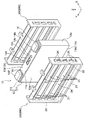
図1は、本発明の実施形態1に係る二次電池モジュール100の外観斜視図である。図2は、図1に示す二次電池モジュール100のダクト部材50を取り外した状態の斜視図である。本実施形態の二次電池モジュール100は、例えば、図示を省略する筐体に収容されて電気自動車やハイブリッド電気自動車等の車両に搭載され、発電機器から供給される電気エネルギーを蓄積し、又は、蓄積した電気エネルギーを電気機器へ供給するモジュールである。
[Embodiment 1]
FIG. 1 is an external perspective view of a secondary battery module 100 according to Embodiment 1 of the present invention. FIG. 2 is a perspective view of the secondary battery module 100 shown in FIG. 1 with the duct member 50 removed. For example, the secondary battery module 100 of the present embodiment is housed in a housing (not shown) and mounted on a vehicle such as an electric vehicle or a hybrid electric vehicle, and accumulates electric energy supplied from a power generator, or This module supplies the stored electrical energy to electrical equipment.

二次電池モジュール100は、複数の二次電池10と、個々の二次電池10を保持するセルホルダ20とを備えている。また、二次電池モジュール100は、交互に積層されたセルホルダ20及び二次電池10の両端に配置された一対のエンドプレート30と、一対のエンドプレート30を接続する一対のサイドプレート40と、を備えている。さらに、二次電池モジュール100は、複数の二次電池10の積層方向に延在し、複数の二次電池10の上方に配置されたダクト部材50を備えている。   The secondary battery module 100 includes a plurality of secondary batteries 10 and a cell holder 20 that holds the individual secondary batteries 10. The secondary battery module 100 includes a cell holder 20 and a pair of end plates 30 disposed at both ends of the secondary battery 10 and a pair of side plates 40 that connect the pair of end plates 30. I have. Further, the secondary battery module 100 includes a duct member 50 that extends in the stacking direction of the plurality of secondary batteries 10 and is disposed above the plurality of secondary batteries 10.

図3は、図1に示す二次電池モジュール100のセルホルダ20と二次電池10を示す斜視図である。図4は、図3に示すセルホルダ20と二次電池10の分解斜視図である。   FIG. 3 is a perspective view showing the cell holder 20 and the secondary battery 10 of the secondary battery module 100 shown in FIG. 4 is an exploded perspective view of the cell holder 20 and the secondary battery 10 shown in FIG.

二次電池モジュール100を構成する複数の二次電池10は、例えば、リチウムイオン二次電池であり、電極を収容する電池缶11と、該電池缶11の開口部11aを封止する電池蓋12と、該電池蓋12に設けられたガス排出弁12aとを有している。詳細については後述するが、本実施形態の二次電池モジュール100は、非常時に作用する外力によりガス排出弁12aを開裂させる位置及び形状に設けられた開弁部材60(図5参照)を備えることを特徴としている。   The plurality of secondary batteries 10 constituting the secondary battery module 100 are, for example, lithium ion secondary batteries, and a battery can 11 that houses electrodes and a battery lid 12 that seals the opening 11a of the battery can 11. And a gas discharge valve 12 a provided on the battery lid 12. Although details will be described later, the secondary battery module 100 of the present embodiment includes a valve-opening member 60 (see FIG. 5) provided at a position and shape that allows the gas discharge valve 12 a to be cleaved by an external force that acts in an emergency. It is characterized by.

特に限定はされないが、本実施形態の二次電池モジュール100は、複数の角形二次電池10を備えている。すなわち、本実施形態の二次電池モジュール100では、複数の二次電池10は、扁平角形の電池缶11の厚さ方向に積層され、電池蓋12は、電池缶11の高さ方向の上端の開口部11aを封止している。なお、各図において、電池缶11又は二次電池10の厚さ方向をX軸方向、幅方向をY軸方向、高さ方向をZ軸方向とするXYZ直交座標系を示している。   Although not particularly limited, the secondary battery module 100 of the present embodiment includes a plurality of prismatic secondary batteries 10. That is, in the secondary battery module 100 of the present embodiment, the plurality of secondary batteries 10 are stacked in the thickness direction of the flat rectangular battery can 11, and the battery lid 12 is at the upper end of the battery can 11 in the height direction. The opening 11a is sealed. In each figure, an XYZ orthogonal coordinate system is shown in which the thickness direction of the battery can 11 or the secondary battery 10 is the X-axis direction, the width direction is the Y-axis direction, and the height direction is the Z-axis direction.

電池缶11及び電池蓋12の素材は、例えば、アルミニウム又はアルミニウム合金等の導電性を有する金属である。電池缶11は、例えば、板材を深絞り加工することによって、上部に概ね長方形の開口部11aを有する有底角筒状の扁平な矩形の箱型に形成されている。電池蓋12は、例えば、鍛造等によって電池缶11の開口部11aの形状に対応する長方形の矩形平板状に形成され、例えば、レーザ溶接によって電池缶11の上部に接合され、電池缶11の開口部11aを封止している。   The material of the battery can 11 and the battery lid 12 is, for example, a metal having conductivity such as aluminum or an aluminum alloy. The battery can 11 is formed into a flat rectangular box shape having a bottomed rectangular tube shape having a substantially rectangular opening 11a at an upper portion, for example, by deep drawing a plate material. The battery lid 12 is formed in a rectangular plate shape corresponding to the shape of the opening 11a of the battery can 11 by forging or the like, for example, and joined to the upper portion of the battery can 11 by laser welding, for example. The part 11a is sealed.

扁平角形の電池缶11と、この電池缶11の上端の開口部11aを封止する矩形板状の電池蓋12とによって、扁平角形の電池容器13が構成されている。電池容器13は、幅と高さに対して厚さが小さい概ね直方体の形状を有することで、厚さ方向の両側に比較的面積の大きい広側面13wを有し、幅方向両側に比較的面積の小さい狭側面13nを有し、高さ方向の上下に幅方向を長手方向とする長方形の底面13b及び上面13tを有している。電池容器13の底面13bは電池缶11の底面11bであり、電池容器13の上面13tは、電池蓋12の上面12tである。   A flat rectangular battery case 11 is constituted by the flat rectangular battery can 11 and a rectangular plate-shaped battery lid 12 that seals the opening 11 a at the upper end of the battery can 11. The battery case 13 has a substantially rectangular parallelepiped shape with a small thickness with respect to the width and height, thereby having wide side surfaces 13w having relatively large areas on both sides in the thickness direction, and relatively large areas on both sides in the width direction. The narrow bottom surface 13n has a rectangular bottom surface 13b and top surface 13t with the width direction as the longitudinal direction at the top and bottom in the height direction. The bottom surface 13 b of the battery container 13 is the bottom surface 11 b of the battery can 11, and the top surface 13 t of the battery container 13 is the top surface 12 t of the battery lid 12.

ガス排出弁12aは、電池蓋12の長手方向の中央部に設けられている。ガス排出弁12aは、例えば、電池蓋12の一部を薄肉化してスリット状の溝を形成することによって形成され、電池容器13の内部の圧力が所定値よりも上昇したときに開裂し、電池容器13の内部のガスを排出することで、電池容器13の内部の圧力を低下させる。なお、薄膜部材を電池蓋12の開口にレーザ溶接等により取り付けて、薄肉部分をガス排出弁12aとしてもよい。   The gas discharge valve 12 a is provided at the center of the battery lid 12 in the longitudinal direction. The gas discharge valve 12a is formed, for example, by thinning a part of the battery lid 12 to form a slit-like groove, which is cleaved when the internal pressure of the battery container 13 rises above a predetermined value. By discharging the gas inside the container 13, the pressure inside the battery container 13 is reduced. A thin film member may be attached to the opening of the battery lid 12 by laser welding or the like, and the thin portion may be used as the gas discharge valve 12a.

二次電池10は、電池蓋12の上面12tに正極外部端子14P及び負極外部端子14Nを備えている。正極外部端子14P及び負極外部端子14Nは、電池蓋12の外部に配置された絶縁部材15及び図示を省略するガスケットを介して電池蓋12と電気的に絶縁されている。   The secondary battery 10 includes a positive external terminal 14P and a negative external terminal 14N on the upper surface 12t of the battery cover 12. The positive external terminal 14P and the negative external terminal 14N are electrically insulated from the battery cover 12 through an insulating member 15 disposed outside the battery cover 12 and a gasket (not shown).

図示は省略するが、正極外部端子14Pは、電池蓋12を貫通する接続部材や電池容器13の内部に収容された正極集電板を介して、電池容器13の内部に収容された正極電極に電気的に接続されている。同様に、負極外部端子14Nは、電池蓋12を貫通する接続部材や電池容器13の内部に収容された負極集電板を介して、電池容器13の内部に収容された負極電極に電気的に接続されている。接続部材や集電板も、正極外部端子14P及び負極外部端子14Nと同様に、絶縁部材によって電池容器13に対して電気的に絶縁されている。   Although not shown, the positive electrode external terminal 14P is connected to the positive electrode accommodated in the battery container 13 via a connecting member penetrating the battery lid 12 or a positive electrode current collector plate accommodated in the battery container 13. Electrically connected. Similarly, the negative electrode external terminal 14N is electrically connected to the negative electrode accommodated in the battery container 13 via a connecting member that penetrates the battery lid 12 and a negative electrode current collector plate accommodated in the battery container 13. It is connected. Similarly to the positive external terminal 14P and the negative external terminal 14N, the connecting member and the current collector are also electrically insulated from the battery case 13 by the insulating member.

図示は省略するが、正極電極及び負極電極は、セパレータと交互に積層されて捲回された捲回電極群として、電池容器13の内部に収容されている。捲回電極群は、例えば、捲回軸方向の一端と他端に露出した正極電極及び負極電極の箔露出部がそれぞれ正極集電板及び負極集電板に接合される。これにより、正極外部端子14P及び負極外部端子14Nは、それぞれ正極集電板及び極集電板を介して正極電極及び負極電極に接続され、絶縁シートによって覆われて電池容器13に対して電気的に絶縁されている。   Although illustration is omitted, the positive electrode and the negative electrode are housed inside the battery container 13 as a wound electrode group that is alternately stacked with the separator and wound. In the wound electrode group, for example, the exposed foil portions of the positive electrode and the negative electrode exposed at one end and the other end in the winding axis direction are joined to the positive current collector and the negative current collector, respectively. Thereby, the positive external terminal 14P and the negative external terminal 14N are connected to the positive electrode and the negative electrode through the positive current collector plate and the positive current collector plate, respectively, and are covered with the insulating sheet and electrically connected to the battery container 13. Is insulated.

電池蓋12の上面12tの正極外部端子14Pと負極外部端子14Nとの間には、注液口12bが設けられている。注液口12bは、電池容器13の内部に電解液を注入するために用いられ、電解液の注入後に、例えばレーザ溶接によって注液栓12cが接合されて封止される。   A liquid injection port 12b is provided between the positive external terminal 14P and the negative external terminal 14N on the upper surface 12t of the battery cover 12. The liquid injection port 12b is used for injecting the electrolytic solution into the battery container 13, and after the injection of the electrolytic solution, the liquid injection plug 12c is joined and sealed, for example, by laser welding.

二次電池モジュール100の個々の二次電池10は、それぞれセルホルダ20によって保持されている。セルホルダ20は、複数の二次電池10の積層方向の両端に配置される一対の端部セルホルダ20Eと、2つの隣接する二次電池10の間に配置される複数の中間セルホルダ20Mによって構成されている。セルホルダ20の素材としては、例えば、ガラスエポキシ樹脂、ポリプロピレン、ポリブチレンテレフタレート樹脂などの樹脂材料や、アルミニウム、銅、ステンレスなどの金属材料を用いることができる。   Each secondary battery 10 of the secondary battery module 100 is held by a cell holder 20. The cell holder 20 includes a pair of end cell holders 20E disposed at both ends in the stacking direction of the plurality of secondary batteries 10 and a plurality of intermediate cell holders 20M disposed between two adjacent secondary batteries 10. Yes. As a material of the cell holder 20, for example, a resin material such as glass epoxy resin, polypropylene, or polybutylene terephthalate resin, or a metal material such as aluminum, copper, or stainless steel can be used.

中間セルホルダ20Mは、図3及び図4に示すように、二次電池10の扁平角形の電池容器13の広側面13wに対向するスペーサ部21と、電池容器13の狭側面13nに対向する側板部22と、電池容器13の底面13bに対向する底板部23とを有している。端部セルホルダ20Eは、中間セルホルダ20Mにおいて、スペーサ部21を中心に二次電池10の厚さ方向の両側に延びる側板部22及び底板部23の片側を、スペーサ部21に沿う平面で切断した構成を有している。そのため、以下では、セルホルダ20の構成として中間セルホルダ20Mの構成を中心に説明し、端部セルホルダ20Eの説明を適宜省略する。   As shown in FIGS. 3 and 4, the intermediate cell holder 20 </ b> M includes a spacer portion 21 that faces the wide side surface 13 w of the flat rectangular battery case 13 of the secondary battery 10 and a side plate portion that faces the narrow side surface 13 n of the battery case 13. 22 and a bottom plate portion 23 facing the bottom surface 13 b of the battery container 13. End cell holder 20E is configured by cutting one side of side plate portion 22 and bottom plate portion 23 extending on both sides in the thickness direction of secondary battery 10 around spacer portion 21 in a plane along spacer portion 21 in intermediate cell holder 20M. have. Therefore, below, it demonstrates centering around the structure of the intermediate | middle cell holder 20M as a structure of the cell holder 20, and abbreviate | omits description of the edge part cell holder 20E suitably.

セルホルダ20は、前述のように、電池容器13の広側面13wに対向するスペーサ部21と、電池容器13の狭側面13nに対向する側板部22と、電池容器13の底面13bに対向する底板部23とを有している。電池缶11の幅方向に間隔を有して対向する一対の長方形の板状の側板部22と、電池缶11の幅方向に延在して一対の側板部22を連結する長方形板状の底板部23とによって、上部が開放されたU字状の保持部24が形成されている。   As described above, the cell holder 20 includes the spacer portion 21 that faces the wide side surface 13w of the battery case 13, the side plate portion 22 that faces the narrow side surface 13n of the battery case 13, and the bottom plate portion that faces the bottom surface 13b of the battery case 13. 23. A pair of rectangular plate-like side plate portions 22 facing each other with a gap in the width direction of the battery can 11, and a rectangular plate-like bottom plate extending in the width direction of the battery can 11 and connecting the pair of side plate portions 22. The portion 23 forms a U-shaped holding portion 24 whose upper portion is open.

セルホルダ20の保持部24は、電池容器13の上面13tを露出させた状態で、電池容器13の厚さの約半分を収容する。対向する一対のセルホルダ20の保持部24に、二次電池10の電池容器13の厚さの約半分ずつを収容することで、二次電池10は、電池容器13の上面13tを露出させた状態で、一対のセルホルダ20の間に保持される。   The holding part 24 of the cell holder 20 accommodates about half of the thickness of the battery container 13 with the upper surface 13t of the battery container 13 exposed. The secondary battery 10 is in a state in which the upper surface 13t of the battery container 13 is exposed by accommodating about half of the thickness of the battery container 13 of the secondary battery 10 in the holding portions 24 of the pair of cell holders 20 facing each other. Thus, it is held between the pair of cell holders 20.

複数のスペーサ部21の間には、電池容器13の幅方向に延びる複数のスリット25が形成されている。また、側板部22には、各スリット25に連通する複数の開口部26が形成されている。セルホルダ20は、二次電池10の電池容器13の広側面13wを冷却する冷却空気等の冷媒を、一方の側板部22の開口部26から導入してスリット25に流通させ、他方の側板部22の開口部26から導出することができるように構成されている。   A plurality of slits 25 extending in the width direction of the battery case 13 are formed between the plurality of spacer portions 21. Further, the side plate portion 22 is formed with a plurality of openings 26 communicating with the respective slits 25. The cell holder 20 introduces a coolant such as cooling air that cools the wide side surface 13 w of the battery container 13 of the secondary battery 10 from the opening 26 of one side plate portion 22 and distributes it through the slit 25, and the other side plate portion 22. It is comprised so that it can derive | lead-out from the opening part 26 of this.

複数の二次電池10は、セルホルダ20によって保持されて厚さ方向に積層して配置されるときに、図2に示すように、隣接する2つの二次電池10の正極外部端子14Pと負極外部端子14Nとが積層方向に隣り合うように、交互に180°反転させて配置される。これにより、複数の二次電池10を不図示のバスバーによって直列に接続することができる。そして、複数の二次電池10の積層方向の両端に配置された一対の端部セルホルダ20Eの外側の平坦な面に対向して一対のエンドプレート30が配置される。   When the plurality of secondary batteries 10 are held by the cell holder 20 and are stacked in the thickness direction, as shown in FIG. 2, the positive external terminals 14P and the negative external terminals of the adjacent two secondary batteries 10 The terminals 14N are alternately inverted by 180 ° so as to be adjacent to each other in the stacking direction. Thereby, the some secondary battery 10 can be connected in series by a bus bar not shown. And a pair of end plate 30 is arrange | positioned facing the flat surface of the outer side of a pair of edge part cell holder 20E arrange | positioned at the both ends of the lamination direction of the some secondary battery 10. FIG.

また、二次電池10の幅方向の両側に、複数のセルホルダ20の側板部22に対向して二次電池10の積層方向に延在する一対のサイドプレート40が配置され、一対のサイドプレート40の延在方向の両端が一対のエンドプレート30に、例えばボルト31によって締結される。これにより、一対のエンドプレート30の間隔が規定され、セルホルダ20の間に配置された複数の二次電池10は、電池容器13の広側面13wにセルホルダ20のスペーサ部21が当接し、圧縮力が付与された状態で、セルホルダ20によって保持される。   In addition, a pair of side plates 40 extending in the stacking direction of the secondary batteries 10 are disposed on both sides of the secondary battery 10 in the width direction so as to face the side plate portions 22 of the plurality of cell holders 20. Both ends in the extending direction are fastened to the pair of end plates 30 by, for example, bolts 31. Thereby, the space | interval of a pair of end plate 30 is prescribed | regulated, and the several secondary batteries 10 arrange | positioned between the cell holders 20 contact | abut the spacer part 21 of the cell holder 20 on the wide side surface 13w of the battery container 13, and compressive force Is held by the cell holder 20.

さらに、図1に示すように、二次電池モジュール100は、複数の二次電池10のガス排出弁12aに対向するダクト部材50を備えている。ダクト部材50は、複数の二次電池10の積層方向に延在する板状の上部壁51と、その周囲を囲む側壁52とを有し、下方が開放された矩形のカバー状の部材である。ダクト部材50は、上部壁51がガス排出弁12aに対向し、側壁52の下端部が電池蓋12の長手方向におけるガス排出弁12aの両側で、電池蓋12に接している。   Furthermore, as shown in FIG. 1, the secondary battery module 100 includes a duct member 50 that faces the gas discharge valves 12 a of the plurality of secondary batteries 10. The duct member 50 is a rectangular cover-like member having a plate-like upper wall 51 extending in the stacking direction of the plurality of secondary batteries 10 and a side wall 52 surrounding the periphery thereof, the lower part being opened. . In the duct member 50, the upper wall 51 faces the gas discharge valve 12 a, and the lower end portion of the side wall 52 is in contact with the battery cover 12 on both sides of the gas discharge valve 12 a in the longitudinal direction of the battery cover 12.

ここで、ガス排出弁12aが電池蓋12の長手方向の中央部に設けられていることで、複数の二次電池10を積層して配置するときに、上述のように交互に180°反転させて配置しても、積層方向に隣接する二次電池10のガス排出弁12aの位置が二次電池10の幅方向にずれることがない。したがって、ダクト部材50を直線的に設けることができ、二次電池モジュール100におけるダクト部材50の取り付けを容易にすることができる。   Here, when the gas discharge valve 12a is provided in the center of the battery lid 12 in the longitudinal direction, when the plurality of secondary batteries 10 are stacked and arranged, they are alternately inverted by 180 ° as described above. The position of the gas discharge valve 12a of the secondary battery 10 adjacent in the stacking direction does not shift in the width direction of the secondary battery 10. Therefore, the duct member 50 can be provided linearly, and attachment of the duct member 50 in the secondary battery module 100 can be facilitated.

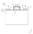
図5は、図1に示すV−V線に沿う二次電池モジュール100の模式的な縦断面図である。図6は、図5に示すVI−VI線に沿う二次電池モジュール100の模式的な平断面図である。図7は、図6に示すVII−VII線に沿う二次電池モジュール100の模式的な横断面図である。   FIG. 5 is a schematic longitudinal sectional view of the secondary battery module 100 taken along line VV shown in FIG. FIG. 6 is a schematic plan sectional view of the secondary battery module 100 taken along the line VI-VI shown in FIG. FIG. 7 is a schematic cross-sectional view of the secondary battery module 100 taken along line VII-VII shown in FIG.

ダクト部材50は、側壁52の下端部が、複数の二次電池10の電池蓋12だけでなく、一対のエンドプレート30の上端及び複数のセルホルダ20の上端に接し、これらの各部材との間にガス流路53を形成する。ダクト部材50のガス流路53の一端には、図5に示すように、ガス排出口54が形成されている。   In the duct member 50, the lower end portion of the side wall 52 is in contact with not only the battery lid 12 of the plurality of secondary batteries 10 but also the upper ends of the pair of end plates 30 and the upper ends of the plurality of cell holders 20. The gas flow path 53 is formed in the above. As shown in FIG. 5, a gas discharge port 54 is formed at one end of the gas flow path 53 of the duct member 50.

本実施形態の二次電池モジュール100は、前述のように、非常時に作用する外力によりガス排出弁12aを開裂させる位置及び形状に設けられた開弁部材60を備えることを特徴としている。より具体的には、本実施形態の二次電池モジュール100において、開弁部材60は、非常時に、二次電池10の高さ方向に作用する圧縮力や衝撃力等の外力を受けて、ガス排出弁12aを機械的に開裂させる位置及び形状に設けられている。   As described above, the secondary battery module 100 according to the present embodiment includes the valve-opening member 60 provided at a position and a shape in which the gas discharge valve 12a is cleaved by an external force acting in an emergency. More specifically, in the secondary battery module 100 of the present embodiment, the valve-opening member 60 receives an external force such as a compressive force or an impact force acting in the height direction of the secondary battery 10 in an emergency, and gas It is provided at a position and a shape for mechanically cleaving the discharge valve 12a.

より詳細には、図5に示すように、開弁部材60は、二次電池10の高さ方向において、下端部61が上端部62よりも薄い楔状の形状を有している。また、開弁部材60は、下端部61が電池蓋12に隣接し、上端部62が電池蓋12よりも上方に配置されている。また、図6に示すように、開弁部材60は、二次電池10の厚さ方向において、電池蓋12に隣接しかつガス排出弁12aと対向する位置に配置されている。より詳細には、開弁部材60は、二次電池10の厚さ方向において、二次電池10の電池容器13の広側面13wとセルホルダ20のスペーサ部21との境界上に位置している。   More specifically, as shown in FIG. 5, the valve opening member 60 has a wedge shape in which the lower end portion 61 is thinner than the upper end portion 62 in the height direction of the secondary battery 10. In addition, the valve opening member 60 has a lower end portion 61 adjacent to the battery lid 12 and an upper end portion 62 disposed above the battery lid 12. Further, as shown in FIG. 6, the valve opening member 60 is disposed at a position adjacent to the battery lid 12 and facing the gas exhaust valve 12 a in the thickness direction of the secondary battery 10. More specifically, the valve opening member 60 is located on the boundary between the wide side surface 13 w of the battery container 13 of the secondary battery 10 and the spacer portion 21 of the cell holder 20 in the thickness direction of the secondary battery 10.

図5に示すようには、開弁部材60の下端部61は、電池蓋12よりも上方に配置され、電池蓋12と高さ方向の間隔を有して隣接しているが、電池蓋12よりも下方に配置されていてもよい。この場合、開弁部材60の下端部61は、二次電池10の厚さ方向すなわち二次電池10の積層方向において、電池蓋12又は電池容器13の広側面13wに隣接するように配置することができる。   As shown in FIG. 5, the lower end portion 61 of the valve opening member 60 is disposed above the battery lid 12 and is adjacent to the battery lid 12 with an interval in the height direction. It may be arranged below. In this case, the lower end portion 61 of the valve opening member 60 is disposed so as to be adjacent to the battery lid 12 or the wide side surface 13w of the battery container 13 in the thickness direction of the secondary battery 10, that is, the stacking direction of the secondary battery 10. Can do.

開弁部材60の材質及び形状は、特に限定されないが、電池蓋12及び電池缶11よりも機械的強度が高く、外力により電池蓋12及び電池缶11を変形させることが可能な材質及び形状を選択する必要がある。例えば、開弁部材60の上端部62の厚さは、非常時に作用する外力によって、開弁部材60の上端部62が二次電池10の電池容器13の広側面13wとセルホルダ20のスペーサ部21との間に食い込んだときに、電池蓋12を二次電池10の厚さ方向に変形させ、ガス排出弁12aを開裂させることができる厚さに設定する。   The material and shape of the valve opening member 60 are not particularly limited, but the material and shape are higher in mechanical strength than the battery lid 12 and the battery can 11 and can deform the battery lid 12 and the battery can 11 by external force. Must be selected. For example, the thickness of the upper end portion 62 of the valve opening member 60 is such that the upper end portion 62 of the valve opening member 60 is separated from the wide side surface 13w of the battery container 13 of the secondary battery 10 and the spacer portion 21 of the cell holder 20 by an external force acting in an emergency. The battery lid 12 is deformed in the thickness direction of the secondary battery 10 and the gas discharge valve 12a is set to a thickness that can be cleaved.

図5に示すように、開弁部材60は、ダクト部材50の上部壁51に設けることができる。開弁部材60は、ダクト部材50と一体成形されていてもよいし、ダクト部材50に対して固定されていてもよい。開弁部材60をダクト部材50に固定する方法は、特に限定されず、例えば、ネジやリベット等の機械的な締結、接着剤による接着、溶接による接合等を用いることができる。   As shown in FIG. 5, the valve opening member 60 can be provided on the upper wall 51 of the duct member 50. The valve opening member 60 may be integrally formed with the duct member 50 or may be fixed to the duct member 50. The method for fixing the valve opening member 60 to the duct member 50 is not particularly limited, and for example, mechanical fastening such as screws and rivets, adhesion with an adhesive, joining by welding, and the like can be used.

図6に示すように、開弁部材60は、二次電池10の幅方向に所定の幅を有し、二次電池10の厚さ方向に所定の厚さを有する板状に形成することができる。また、二次電池10の幅方向において、開弁部材60の幅は、特に限定されないが、例えば、ガス排出弁12aの寸法と同程度にすることができる。   As shown in FIG. 6, the valve opening member 60 may be formed in a plate shape having a predetermined width in the width direction of the secondary battery 10 and having a predetermined thickness in the thickness direction of the secondary battery 10. it can. Further, in the width direction of the secondary battery 10, the width of the valve opening member 60 is not particularly limited, but can be, for example, approximately the same as the dimension of the gas discharge valve 12 a.

図7に示すように、ダクト部材50によって形成されるガス流路53の流路面積を確保する観点から、開弁部材60の幅は、ガス流路53の幅よりも狭いことが好ましい。また、開弁部材60の幅は、上端部62の幅よりも下端部61の幅が狭くなるテーパ状に形成されていてもよい。   As shown in FIG. 7, the width of the valve opening member 60 is preferably narrower than the width of the gas channel 53 from the viewpoint of securing the channel area of the gas channel 53 formed by the duct member 50. Further, the width of the valve opening member 60 may be formed in a tapered shape in which the width of the lower end portion 61 is narrower than the width of the upper end portion 62.

以下、本実施形態の二次電池モジュール100の作用について説明する。   Hereinafter, the operation of the secondary battery module 100 of the present embodiment will be described.

本実施形態の二次電池モジュール100は、例えば、不図示の筐体に収容されて、電気自動車やハイブリッド電気自動車等の車両に搭載される。例えば、車両の衝突等の非常時に、二次電池モジュール100を収容する筐体が圧縮力や衝撃力を受けて圧壊するなど、二次電池モジュール100に対し、二次電池10の幅方向、厚さ方向、高さ方向に圧縮力や衝撃力が作用することが想定される。   The secondary battery module 100 of the present embodiment is housed in a housing (not shown) and mounted on a vehicle such as an electric vehicle or a hybrid electric vehicle. For example, in the event of an emergency such as a vehicle collision, the casing that accommodates the secondary battery module 100 receives a compressive force or an impact force and is crushed. It is assumed that compressive force and impact force act in the vertical direction and the vertical direction.

このような非常時に作用する衝撃力や圧縮力によって、異常が発生して二次電池10の内部の温度が上昇し、電池容器13の内圧が所定の圧力を超えて上昇すると、電池蓋12に設けられたガス排出弁12aが開裂してミスト状のガスを排出する。二次電池10から排出されたガスは、ダクト部材50によって形成されたガス流路53によって二次電池モジュール100から排出される。   When an abnormality occurs due to the impact force or compression force acting in such an emergency and the temperature inside the secondary battery 10 rises and the internal pressure of the battery container 13 rises above a predetermined pressure, the battery lid 12 The provided gas discharge valve 12a is cleaved to discharge mist-like gas. The gas discharged from the secondary battery 10 is discharged from the secondary battery module 100 through the gas flow path 53 formed by the duct member 50.

しかし、例えば、二次電池10が内部短絡によって熱暴走に至ると、二次電池10の内圧が急激に上昇し、内圧上昇によるガス排出弁12aの開裂では十分な安全性が確保できない虞がある。   However, for example, when the secondary battery 10 reaches a thermal runaway due to an internal short circuit, the internal pressure of the secondary battery 10 rapidly increases, and there is a possibility that sufficient safety cannot be ensured by cleaving the gas discharge valve 12a due to the internal pressure increase. .

そこで、本実施形態の二次電池モジュール100は、非常時に作用する外力によりガス排出弁12aを開裂させる位置及び形状に設けられた開弁部材60を備えている。これにより、非常時に作用する外力によって、開弁部材60がガス排出弁12aに機械的な応力を作用させ、電池容器13の内圧上昇を待つことなく、ガス排出弁12aを開裂させることができる。   Therefore, the secondary battery module 100 of the present embodiment includes a valve opening member 60 provided at a position and a shape where the gas discharge valve 12a is cleaved by an external force acting in an emergency. Thereby, the valve opening member 60 applies mechanical stress to the gas discharge valve 12a by an external force acting in an emergency, and the gas discharge valve 12a can be opened without waiting for the internal pressure of the battery container 13 to rise.

より具体的には、本実施形態の二次電池モジュール100は、複数の二次電池10が扁平角形の電池缶11の厚さ方向に積層され、電池蓋12が電池缶11の高さ方向の上端の開口部11aを封止する構成を有し、開弁部材60は以下の構成を有している。   More specifically, in the secondary battery module 100 of the present embodiment, a plurality of secondary batteries 10 are stacked in the thickness direction of the flat rectangular battery can 11, and the battery lid 12 extends in the height direction of the battery can 11. The upper end opening 11a is sealed, and the valve opening member 60 has the following configuration.

開弁部材60は、二次電池10の高さ方向において、下端部61が上端部62よりも薄い楔状の形状を有し、該下端部61が電池蓋12に隣接し、該上端部62が前記電池蓋12よりも上方に配置されている。また、開弁部材60は、二次電池10の厚さ方向において、電池蓋12に隣接し、ガス排出弁12aと対向する位置に配置されている。これにより、非常時に開弁部材60に作用する二次電池10の高さ方向の外力によって、二次電池10の厚さ方向において、電池蓋12に圧縮力を作用させ、ガス排出弁12aを開裂させることができる。   The valve opening member 60 has a wedge-like shape in which the lower end 61 is thinner than the upper end 62 in the height direction of the secondary battery 10, the lower end 61 is adjacent to the battery lid 12, and the upper end 62 is It is disposed above the battery lid 12. Further, the valve opening member 60 is disposed at a position adjacent to the battery lid 12 and facing the gas discharge valve 12a in the thickness direction of the secondary battery 10. As a result, the external force in the height direction of the secondary battery 10 acting on the valve opening member 60 in the event of an emergency causes a compressive force to act on the battery lid 12 in the thickness direction of the secondary battery 10 to open the gas discharge valve 12a. Can be made.

より詳細には、開弁部材60に対して二次電池10の高さ方向の下方へ向かう外力が作用すると、開弁部材60は、隣接する二次電池10の電池容器13の広側面13wの間、又は、広側面13wとセルホルダ20のスペーサ部21材との間に、下端部61から上端部62まで食い込んだ状態になる。開弁部材60は、上端部62の厚さが下端部61の厚さよりも厚い楔状の形状を有する。そのため、開弁部材60が上記のように食い込むことで、電池容器13の上部が厚さ方向に圧縮され、電池蓋12に対して二次電池10の厚さ方向の圧縮力が作用する。   More specifically, when an external force directed downward in the height direction of the secondary battery 10 acts on the valve-opening member 60, the valve-opening member 60 moves to the wide side surface 13 w of the battery container 13 of the adjacent secondary battery 10. In the middle or between the wide side surface 13w and the spacer part 21 material of the cell holder 20, the lower end 61 and the upper end 62 are bitten. The valve opening member 60 has a wedge shape in which the thickness of the upper end portion 62 is thicker than the thickness of the lower end portion 61. Therefore, when the valve opening member 60 bites in as described above, the upper part of the battery container 13 is compressed in the thickness direction, and the compressive force in the thickness direction of the secondary battery 10 acts on the battery lid 12.

このとき、開弁部材60は、二次電池10の厚さ方向において、電池蓋12に隣接し、ガス排出弁12aと対向する位置に配置されていることから、電池蓋12に対して二次電池10の厚さ方向の圧縮力が作用するとガス排出弁12aに機械的な応力が作用する。そして、例えば、ガス排出弁12aのスリットに応力が集中するなどして、ガス排出弁12aが開裂する。   At this time, since the valve opening member 60 is disposed in a position adjacent to the battery lid 12 and facing the gas exhaust valve 12a in the thickness direction of the secondary battery 10, the secondary member 60 is secondary to the battery lid 12. When a compressive force in the thickness direction of the battery 10 acts, mechanical stress acts on the gas discharge valve 12a. Then, for example, the stress is concentrated on the slit of the gas discharge valve 12a, and the gas discharge valve 12a is cleaved.

したがって、本実施形態の二次電池モジュール100によれば、非常時に二次電池10の内圧上昇を待つことなくガス排出弁12aを開裂させ、電池容器13の内圧上昇を従来よりも確実に防止することができ、従来よりも安全性を向上させることができる。   Therefore, according to the secondary battery module 100 of the present embodiment, the gas discharge valve 12a is cleaved without waiting for an increase in the internal pressure of the secondary battery 10 in an emergency, and the increase in the internal pressure of the battery container 13 is prevented more reliably than before. And safety can be improved as compared with the conventional case.

また、本実施形態の二次電池モジュール100のように、セルホルダ20を備える場合には、二次電池10の厚さ方向において、二次電池10の電池容器13の広側面13wとセルホルダ20のスペーサ部21との境界上に、開弁部材60が位置することが好ましい。これにより、電池容器13の広側面13wと電池ホルダのスペーサ部21材との間に、開弁部材60を食い込ませやすくなる。   Further, when the cell holder 20 is provided as in the secondary battery module 100 of the present embodiment, the wide side surface 13w of the battery container 13 of the secondary battery 10 and the spacer of the cell holder 20 in the thickness direction of the secondary battery 10 are used. It is preferable that the valve opening member 60 is located on the boundary with the portion 21. Thereby, it becomes easy to bite the valve opening member 60 between the wide side surface 13w of the battery container 13 and the spacer part 21 material of a battery holder.

また、二次電池モジュール100がセルホルダ20を有しない場合には、厚さ方向に積層して配置された複数の二次電池10は、電池容器13の広側面13w同士が接触する。この場合に、開弁部材60は、二次電池10の厚さ方向において、二次電池10の電池容器13の広側面13w同士の境界上に位置することが好ましい。これにより、電池容器13の広側面13w同士の間に、開弁部材60を食い込ませやすくなる。   Further, when the secondary battery module 100 does not have the cell holder 20, the wide side surfaces 13 w of the battery container 13 are in contact with the plurality of secondary batteries 10 that are stacked in the thickness direction. In this case, the valve opening member 60 is preferably located on the boundary between the wide side surfaces 13 w of the battery container 13 of the secondary battery 10 in the thickness direction of the secondary battery 10. Thereby, it becomes easy to bite the valve-opening member 60 between the wide side surfaces 13w of the battery case 13.

また、図7に示すように、開弁部材60の幅は、上端部62の幅よりも下端部61の幅が狭くなるテーパ状に形成されている。これにより、開弁部材60を、電池容器13の広側面13wとセルホルダ20のスペーサ部21材との間、又は、電池容器13の広側面13w同士の間に食い込ませるときに、開弁部材60に作用する摩擦力を減少させ、開弁部材60を食い込ませやすくすることができる。また、ダクト部材50によって形成されるガス流路53の流路面積を拡大させ、ガス流路53の流路抵抗を減少させることができる。   As shown in FIG. 7, the width of the valve opening member 60 is formed in a tapered shape in which the width of the lower end 61 is narrower than the width of the upper end 62. Thereby, when the valve opening member 60 is made to bite between the wide side surface 13w of the battery container 13 and the spacer part 21 material of the cell holder 20, or between the wide side surfaces 13w of the battery container 13, the valve opening member 60 It is possible to reduce the frictional force acting on the valve opening member 60 and to easily bite the valve opening member 60. Further, the flow area of the gas flow path 53 formed by the duct member 50 can be increased, and the flow resistance of the gas flow path 53 can be reduced.

また、本実施形態の二次電池モジュール100は、複数の二次電池10のガス排出弁12aに対向するダクト部材50を備え、開弁部材60は、ダクト部材50に設けられている。これにより、上述のように、開弁部材60を、非常時に作用する外力によりガス排出弁12aを開裂させる位置に配置するのが容易になる。   Further, the secondary battery module 100 of the present embodiment includes a duct member 50 that faces the gas discharge valves 12 a of the plurality of secondary batteries 10, and the valve opening member 60 is provided in the duct member 50. Thereby, as described above, it becomes easy to dispose the valve opening member 60 at a position where the gas discharge valve 12a is cleaved by an external force acting in an emergency.

以上説明したように、本実施形態によれば、非常時に二次電池10の内圧の上昇をより確実に防止することができる安全性の高い二次電池モジュール100を提供することができる。   As described above, according to this embodiment, it is possible to provide a highly safe secondary battery module 100 that can more reliably prevent an increase in internal pressure of the secondary battery 10 in an emergency.

[実施形態2]
次に、本発明の実施形態2について、図1から図4及び図6を援用し、図8を用いて説明する。図8は、本発明の実施形態2に係る二次電池モジュール100Aの模式的な縦断面図であり、前述の実施形態1の二次電池モジュール100の図5に相当する断面図である。
[Embodiment 2]
Next, Embodiment 2 of the present invention will be described with reference to FIGS. 1 to 4 and 6 and FIG. FIG. 8 is a schematic longitudinal sectional view of a secondary battery module 100A according to Embodiment 2 of the present invention, and is a sectional view corresponding to FIG. 5 of the secondary battery module 100 of Embodiment 1 described above.

本実施形態の二次電池モジュール100Aは、ダクト部材50を有しない点、及び、開弁部材60がセルホルダ20に固定されている点で、前述の実施形態1の二次電池モジュール100と異なっている。本実施形態の二次電池モジュール100Aのその他の点は、前述の実施形態1の二次電池モジュール100と同一であるので、同一の部分には同一の符号を付して説明を省略する。   The secondary battery module 100A of the present embodiment is different from the secondary battery module 100 of the first embodiment described above in that the duct member 50 is not provided and the valve opening member 60 is fixed to the cell holder 20. Yes. Since other points of the secondary battery module 100A of the present embodiment are the same as those of the secondary battery module 100 of the above-described first embodiment, the same portions are denoted by the same reference numerals and description thereof is omitted.

本実施形態の二次電池モジュール100Aは、前述の実施形態1の二次電池モジュール100と同様に、複数の二次電池10を保持するセルホルダ20を備えている。そして、本実施形態の二次電池モジュール100Aでは、開弁部材60は、セルホルダ20に設けられている。より具体的には、開弁部材60は、セルホルダ20のスペーサ部21の上端部に固定され、二次電池10の厚さ方向において、図6に示す前述の実施形態1の二次電池モジュール100の開弁部材60と同様の位置に配置されている。   Similar to the secondary battery module 100 of the first embodiment described above, the secondary battery module 100 </ b> A of the present embodiment includes a cell holder 20 that holds a plurality of secondary batteries 10. In the secondary battery module 100 </ b> A of the present embodiment, the valve opening member 60 is provided in the cell holder 20. More specifically, the valve opening member 60 is fixed to the upper end portion of the spacer portion 21 of the cell holder 20, and in the thickness direction of the secondary battery 10, the secondary battery module 100 of the first embodiment shown in FIG. The valve opening member 60 is disposed at the same position.

セルホルダ20に対する開弁部材60の固定方法は、特に限定されないが、例えば、インサート成形によってセルホルダ20のスペーサ部21に開弁部材60の端部を埋め込んで固定することができる。また、開弁部材60は、セルホルダ20のスペーサ部21に、ボルトやリベット等の機械的な締結手段や、接着剤又は粘着テープによって固定してもよい。   The method for fixing the valve opening member 60 to the cell holder 20 is not particularly limited. For example, the end portion of the valve opening member 60 can be embedded and fixed in the spacer portion 21 of the cell holder 20 by insert molding. Further, the valve opening member 60 may be fixed to the spacer portion 21 of the cell holder 20 by a mechanical fastening means such as a bolt or a rivet, an adhesive, or an adhesive tape.

本実施形態の二次電池モジュール100Aによれば、前述の実施形態1の二次電池モジュール100と同様に、開弁部材60を、非常時に作用する外力によりガス排出弁12aを開裂させる位置に配置することができ、前述の実施形態1の二次電池モジュール100と同様の効果を得ることができる。また、開弁部材60をセルホルダ20に固定することで、二次電池10の高さ方向における二次電池モジュール100Aの寸法をより小さくすることができる。   According to the secondary battery module 100A of the present embodiment, like the secondary battery module 100 of the first embodiment, the valve opening member 60 is disposed at a position where the gas discharge valve 12a is cleaved by an external force acting in an emergency. Thus, the same effects as those of the secondary battery module 100 of the first embodiment can be obtained. In addition, by fixing the valve opening member 60 to the cell holder 20, the size of the secondary battery module 100 </ b> A in the height direction of the secondary battery 10 can be further reduced.

[実施形態3]
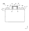
次に、本発明の実施形態3について、図1から図4を援用し、図9から図11を用いて説明する。図9は、本発明の実施形態3に係る二次電池モジュール100Bの模式的な縦断面図であり、実施形態1に係る二次電池モジュール100の図5に相当する断面図である。図10は、図9に示すX−X線に沿う二次電池モジュール100Bの模式的な平断面図である。図11は、図10に示すXI−XI線に沿う二次電池モジュール100Bの模式的な横断面図である。
[Embodiment 3]
Next, Embodiment 3 of the present invention will be described with reference to FIGS. 9 to 11 with reference to FIGS. FIG. 9 is a schematic longitudinal sectional view of a secondary battery module 100B according to Embodiment 3 of the present invention, and is a sectional view corresponding to FIG. 5 of the secondary battery module 100 according to Embodiment 1. FIG. 10 is a schematic plan sectional view of the secondary battery module 100B along the line XX shown in FIG. FIG. 11 is a schematic cross-sectional view of the secondary battery module 100B along the line XI-XI shown in FIG.

本実施形態の二次電池モジュール100Bは、開弁部材60の位置及び形状が前述の実施形態1の二次電池モジュール100と異なっている。本実施形態の二次電池モジュール100Bのその他の点は、前述の実施形態1の二次電池モジュール100と同一であるので、同一の部分には同一の符号を付して説明を省略する。   The secondary battery module 100B of the present embodiment is different from the secondary battery module 100 of the first embodiment described above in the position and shape of the valve opening member 60. Since the other points of the secondary battery module 100B of the present embodiment are the same as those of the secondary battery module 100 of the first embodiment described above, the same portions are denoted by the same reference numerals and description thereof is omitted.

本実施形態の二次電池モジュール100Bにおいて、開弁部材60は、図9及び図11に示すに示すように、高さ方向において下方に突出する突起状の形状を有し、下端部61が電池蓋12に対向して配置されている。また、本実施形態の二次電池モジュール100Bにおいて、開弁部材60は、図10に示すように、電池缶11の幅方向において、ガス排出弁12aに隣接して両側に配置されている。   In the secondary battery module 100B of the present embodiment, as shown in FIGS. 9 and 11, the valve opening member 60 has a protruding shape that protrudes downward in the height direction, and the lower end 61 is a battery. It is arranged opposite to the lid 12. Further, in the secondary battery module 100B of the present embodiment, the valve opening members 60 are disposed on both sides adjacent to the gas discharge valve 12a in the width direction of the battery can 11 as shown in FIG.

より詳細には、開弁部材60は、図10に示すように、二次電池10の厚さ方向に所定の幅を有し、二次電池10の幅方向に所定の厚さを有する板状に形成することができる。二次電池10の厚さ方向において、開弁部材60の幅は、特に限定されないが、例えば、電池蓋12の幅以下で、ガス排出弁12aの寸法以上にすることができる。   More specifically, as shown in FIG. 10, the valve opening member 60 has a predetermined width in the thickness direction of the secondary battery 10 and a plate shape having a predetermined thickness in the width direction of the secondary battery 10. Can be formed. In the thickness direction of the secondary battery 10, the width of the valve opening member 60 is not particularly limited. For example, the width of the valve opening member 60 is equal to or smaller than the width of the battery lid 12 and larger than the dimension of the gas discharge valve 12 a.

また、図9に示すように、開弁部材60は、二次電池10の厚さ方向において、上端部62の幅が下端部61の幅よりも広いテーパ状に形成することができる。また、図11に示すように、開弁部材60は、二次電池10の幅方向において、下端部61の厚さが上端部62の厚さよりも薄いテーパ状に形成することができる。   As shown in FIG. 9, the valve opening member 60 can be formed in a tapered shape in which the width of the upper end 62 is wider than the width of the lower end 61 in the thickness direction of the secondary battery 10. As shown in FIG. 11, the valve opening member 60 can be formed in a tapered shape in which the thickness of the lower end portion 61 is thinner than the thickness of the upper end portion 62 in the width direction of the secondary battery 10.

本実施形態の二次電池モジュール100Bは、非常時に開弁部材60に対して二次電池10の高さ方向の下方へ向かう外力が作用すると、二次電池10の電池蓋12の長手方向の中央部に設けられたガス排出弁12aの両側に、二次電池10の高さ方向の下方へ向かう力を作用させる。これにより、二次電池10の電池蓋12に曲げ応力が作用し、ガス排出弁12aに引張応力や圧縮応力が作用し、例えば、ガス排出弁12aのスリットに応力が集中するなどして、ガス排出弁12aが開裂する。   In the secondary battery module 100B of the present embodiment, when an external force directed downward in the height direction of the secondary battery 10 acts on the valve opening member 60 in an emergency, the center of the battery lid 12 of the secondary battery 10 in the longitudinal direction is provided. A downward force in the height direction of the secondary battery 10 is applied to both sides of the gas discharge valve 12a provided in the section. As a result, bending stress acts on the battery lid 12 of the secondary battery 10, tensile stress or compressive stress acts on the gas discharge valve 12 a, for example, stress concentrates on the slit of the gas discharge valve 12 a, and so on. The discharge valve 12a is cleaved.

ここで、上記のように開弁部材60がテーパ状の形状を有することで、開弁部材60の機械的強度を向上させることができるだけでなく、外力を受けた開弁部材60の下端部61によって電池蓋12に加えられる力を増加させることができる。   Here, since the valve opening member 60 has a tapered shape as described above, not only can the mechanical strength of the valve opening member 60 be improved, but also the lower end portion 61 of the valve opening member 60 that has received an external force. The force applied to the battery cover 12 can be increased.

したがって、本実施形態の二次電池モジュール100Bによれば、非常時に二次電池10の内圧上昇を待つことなくガス排出弁12aを開裂させ、電池容器13の内圧上昇を従来よりも確実に防止することができ、従来よりも安全性を向上させることができる。   Therefore, according to the secondary battery module 100B of the present embodiment, the gas discharge valve 12a is cleaved without waiting for an increase in the internal pressure of the secondary battery 10 in an emergency, and the increase in the internal pressure of the battery container 13 is prevented more reliably than before. And safety can be improved as compared with the conventional case.

また、開弁部材60は、図10に示すように、二次電池10の厚さ方向に所定の幅を有し、二次電池10の幅方向に所定の厚さを有する板状に形成されている。これにより、二次電池10の厚さ方向、すなわち複数の二次電池10の積層方向に延在するダクト部材50によって形成されるガス流路53の流路抵抗を減少させることができる。そのため、開弁部材60の設置場所の自由度をより高くすることができる。   Further, as shown in FIG. 10, the valve opening member 60 is formed in a plate shape having a predetermined width in the thickness direction of the secondary battery 10 and having a predetermined thickness in the width direction of the secondary battery 10. ing. Thereby, the flow resistance of the gas flow path 53 formed by the duct member 50 extending in the thickness direction of the secondary battery 10, that is, in the stacking direction of the plurality of secondary batteries 10 can be reduced. Therefore, the degree of freedom of the installation location of the valve opening member 60 can be further increased.

なお、本実施形態では、二次電池モジュール100Bがセルホルダ20を有する構成について説明したが、二次電池モジュール100Bは、セルホルダ20を有しなくてもよい。この場合にも、二次電池モジュール100Bがセルホルダ20を有する場合と同様の効果を得ることができる。   In addition, in this embodiment, although the secondary battery module 100B demonstrated the structure which has the cell holder 20, the secondary battery module 100B does not need to have the cell holder 20. FIG. Also in this case, the same effect as the case where the secondary battery module 100B has the cell holder 20 can be obtained.

[実施形態4]
次に、本発明の実施形態4について、図1から図5を援用し、図12を用いて説明する。図12は、本発明の実施形態4に係る二次電池モジュール100Cの模式的な平断面図であり、実施形態1に係る二次電池モジュール100の図6に相当する断面図である。
[Embodiment 4]
Next, Embodiment 4 of the present invention will be described with reference to FIGS. 12 is a schematic plan sectional view of a secondary battery module 100C according to Embodiment 4 of the present invention, and is a sectional view corresponding to FIG. 6 of the secondary battery module 100 according to Embodiment 1. FIG.

本実施形態の二次電池モジュール100Cは、非常時に、開弁部材60が電池蓋12を変形させてガス排出弁12aを間接的に開裂させるのではなく、開弁部材60がガス排出弁12aを直接的に開裂させることができる位置及び形状に設けられている点で、前述の実施形態1の二次電池モジュール100と異なっている。本実施形態の二次電池モジュール100Cのその他の点は、前述の実施形態1の二次電池モジュール100と同一であるので、同一の部分には同一の符号を付して説明を省略する。   In the secondary battery module 100C of the present embodiment, the valve opening member 60 does not indirectly deform the gas discharge valve 12a by deforming the battery lid 12 in an emergency, but the valve opening member 60 does not open the gas discharge valve 12a. It differs from the secondary battery module 100 of Embodiment 1 described above in that it is provided in a position and shape that can be directly cleaved. Since the other points of the secondary battery module 100C of the present embodiment are the same as those of the secondary battery module 100 of the above-described first embodiment, the same portions are denoted by the same reference numerals and description thereof is omitted.

本実施形態の二次電池モジュール100Cにおいて、開弁部材60は、図5に示す実施形態1の二次電池モジュール100の開弁部材60と同様に、高さ方向において下方に突出する突起状の形状を有している。しかし、図5に示す実施形態1の二次電池モジュール100の開弁部材60とは異なり、下端部61がガス排出弁12aに対向して配置されている。   In the secondary battery module 100C of the present embodiment, the valve opening member 60 has a protruding shape that protrudes downward in the height direction, like the valve opening member 60 of the secondary battery module 100 of the first embodiment shown in FIG. It has a shape. However, unlike the valve opening member 60 of the secondary battery module 100 of Embodiment 1 shown in FIG. 5, the lower end 61 is disposed to face the gas discharge valve 12a.

また、開弁部材60は、図12に示すように、高さ方向に垂直な断面積がガス排出弁12aの面積よりも小さい。また、開弁部材60は、二次電池10の厚さ方向に所定の厚さを有し、二次電池10の幅方向に所定の幅を有する板状に形成されている。開弁部材60の厚さは、二次電池10の厚さ方向におけるガス排出弁12aの寸法よりも薄く、開弁部材60の幅は、二次電池10の幅方向におけるガス排出弁12aの寸法よりも狭い。   Further, as shown in FIG. 12, the valve opening member 60 has a cross-sectional area perpendicular to the height direction smaller than the area of the gas discharge valve 12a. Further, the valve opening member 60 has a predetermined thickness in the thickness direction of the secondary battery 10 and is formed in a plate shape having a predetermined width in the width direction of the secondary battery 10. The thickness of the valve opening member 60 is thinner than the dimension of the gas exhaust valve 12a in the thickness direction of the secondary battery 10, and the width of the valve opening member 60 is the dimension of the gas exhaust valve 12a in the width direction of the secondary battery 10. Narrower than.

本実施形態の二次電池モジュール100Cは、非常時に開弁部材60に対して二次電池10の高さ方向の下方へ向かう外力が作用すると、開弁部材60の下端がガス排出弁12aに当接し、二次電池10の高さ方向の下方へ向かう力を作用させる。これにより、開弁部材60からガス排出弁12aに機械的な応力が直接的に作用し、例えば、ガス排出弁12aのスリットに応力が集中するなどして、ガス排出弁12aが開裂する。   In the secondary battery module 100C of the present embodiment, when an external force directed downward in the height direction of the secondary battery 10 acts on the valve opening member 60 in an emergency, the lower end of the valve opening member 60 contacts the gas discharge valve 12a. In contact therewith, a downward force in the height direction of the secondary battery 10 is applied. As a result, mechanical stress directly acts on the gas exhaust valve 12a from the valve opening member 60, and the gas exhaust valve 12a is cleaved, for example, due to stress concentration on the slit of the gas exhaust valve 12a.

したがって、本実施形態の二次電池モジュール100Cによれば、非常時に二次電池10の内圧上昇を待つことなくガス排出弁12aを開裂させ、電池容器13の内圧が上昇するのを従来よりも確実に防止することができ、従来よりも安全性を向上させることができる。また、開弁部材60からガス排出弁12aに機械的な応力を直接的に作用させることで、より迅速かつ確実にガス排出弁12aを開裂させることができる。   Therefore, according to the secondary battery module 100C of the present embodiment, the gas discharge valve 12a is opened without waiting for the internal pressure of the secondary battery 10 to rise in an emergency, and the internal pressure of the battery container 13 is more reliably increased than before. Therefore, safety can be improved as compared with the conventional case. In addition, by directly applying mechanical stress from the valve opening member 60 to the gas discharge valve 12a, the gas discharge valve 12a can be cleaved more quickly and reliably.

また、開弁部材60は、高さ方向に垂直な断面積がガス排出弁12aの面積よりも小さいため、開弁部材60がガス排出弁12aを完全に塞ぐことがなく、ガス排出弁12aからのガスの排出経路を確保することができる。なお、本実施形態では、二次電池モジュール100Cがセルホルダ20を有する場合について説明したが、二次電池モジュール100Cがセルホルダ20を有しない場合にも、同様の効果を得ることができる。   Further, since the valve opening member 60 has a cross-sectional area perpendicular to the height direction smaller than the area of the gas discharge valve 12a, the valve opening member 60 does not completely block the gas discharge valve 12a. It is possible to secure a gas discharge route. In addition, although this embodiment demonstrated the case where the secondary battery module 100C had the cell holder 20, the same effect can be acquired also when the secondary battery module 100C does not have the cell holder 20.

[実施形態5]
次に、本発明の実施形態5について、図1から図4を援用し、図13から図15を用いて説明する。図13は、本発明の実施形態5に係る二次電池モジュール100Dの模式的な縦断面図であり、実施形態1の二次電池モジュール100の図5に相当する断面図である。図14は、図13に示す二次電池モジュール100Dの模式的な平面図である。図15は、図14に示すXV-XV線に沿う二次電池モジュール100Dの模式的な横断面図である。
[Embodiment 5]
Next, Embodiment 5 of the present invention will be described with reference to FIGS. 13 to 15 with reference to FIGS. FIG. 13 is a schematic longitudinal sectional view of a secondary battery module 100D according to Embodiment 5 of the present invention, and is a sectional view corresponding to FIG. 5 of the secondary battery module 100 of Embodiment 1. FIG. 14 is a schematic plan view of the secondary battery module 100D shown in FIG. FIG. 15 is a schematic cross-sectional view of the secondary battery module 100D along the line XV-XV shown in FIG.

本実施形態の二次電池モジュール100Dは、ダクト部材50を有していない点、開弁部材60の形状、及び開弁部材60の配置方法が、前述の実施形態4の二次電池モジュール100Cと異なっている。本実施形態の二次電池モジュール100Dのその他の点は、前述の実施形態4の二次電池モジュール100Cと同一であるので、同一の部分には同一の符号を付して説明を省略する。   The secondary battery module 100D of the present embodiment is different from the secondary battery module 100C of the fourth embodiment described above in that the duct member 50 is not provided, the shape of the valve opening member 60, and the arrangement method of the valve opening member 60 are the same as those in the above-described fourth embodiment. Is different. Since the other points of the secondary battery module 100D of the present embodiment are the same as those of the secondary battery module 100C of the above-described fourth embodiment, the same portions are denoted by the same reference numerals and description thereof is omitted.

本実施形態の二次電池モジュール100Dにおいて、開弁部材60は、高さ方向において下方に突出する突起状の形状を有し、下端部61がガス排出弁12aに対向して配置されている。また、開弁部材60は、高さ方向に垂直な断面積がガス排出弁12aの面積よりも小さい。より具体的には、開弁部材60は、棒状、柱状、又は針状等の細長い形状に形成されている。また、開弁部材60は、下端部61の太さが上端部62の太さよりも細いテーパ状の形状に形成されている。   In the secondary battery module 100D of the present embodiment, the valve opening member 60 has a protruding shape that protrudes downward in the height direction, and the lower end portion 61 is disposed to face the gas discharge valve 12a. Further, the valve opening member 60 has a cross-sectional area perpendicular to the height direction that is smaller than the area of the gas discharge valve 12a. More specifically, the valve opening member 60 is formed in an elongated shape such as a rod shape, a column shape, or a needle shape. Further, the valve opening member 60 is formed in a tapered shape in which the thickness of the lower end portion 61 is thinner than the thickness of the upper end portion 62.

本実施形態の二次電池モジュール100Dにおいて、複数の二次電池10に対応して設けられた複数の開弁部材60の上端部62は、二次電池10の積層方向に延在する棒状又は柱状の細長い連結部材63に連結されている。複数の開弁部材60と連結部材63は、例えば一体成形により一体に設けられている。連結部材63の両端は、例えば、端部セルホルダ20Eに固定することができる。   In the secondary battery module 100 </ b> D of the present embodiment, the upper ends 62 of the plurality of valve opening members 60 provided corresponding to the plurality of secondary batteries 10 are rod-shaped or columnar extending in the stacking direction of the secondary batteries 10. Are connected to the elongated connecting member 63. The plurality of valve opening members 60 and the connecting member 63 are integrally provided, for example, by integral molding. Both ends of the connecting member 63 can be fixed to the end cell holder 20E, for example.

本実施形態の二次電池モジュール100Dによれば、前述の実施形態4の二次電池モジュール100Cと同様に、非常時に二次電池10の内圧上昇を待つことなくガス排出弁12aを開裂させ、電池容器13の内圧が上昇するのを従来よりも確実に防止することができ、従来よりも安全性を向上させることができる。また、前述の実施形態4の二次電池モジュール100Cと比較して、二次電池10の高さ方向に垂直な開弁部材60の断面積が小さいので、より確実にガス排出弁12aを開裂させることができる。   According to the secondary battery module 100D of the present embodiment, as in the case of the secondary battery module 100C of the above-described fourth embodiment, the gas discharge valve 12a is cleaved without waiting for the internal pressure of the secondary battery 10 to rise in the event of an emergency. An increase in the internal pressure of the container 13 can be prevented more reliably than before, and safety can be improved as compared with the conventional case. Further, since the cross-sectional area of the valve opening member 60 perpendicular to the height direction of the secondary battery 10 is small as compared with the secondary battery module 100C of the fourth embodiment described above, the gas discharge valve 12a is more reliably cleaved. be able to.

なお、本実施形態の二次電池モジュール100Dでは、連結部材63によって連結された複数の開弁部材60をガス排出弁12aの上方に配置して、非常時に開弁部材60によってガス排出弁12aを直接的に開裂させる構成とした。しかし、連結部材63によって連結された複数の開弁部材60を、二次電池10の幅方向において、ガス排出弁12aの両側に配置してもよい。これにより、前述の実施形態3の二次電池モジュール100Bと同様に、非常時に開弁部材60によって電池蓋12を変形させて、ガス排出弁12aを間接的に開裂させることができる。   In the secondary battery module 100D of the present embodiment, a plurality of valve opening members 60 connected by the connecting member 63 are arranged above the gas discharge valve 12a, and the gas discharge valve 12a is set by the valve opening member 60 in an emergency. It was set as the structure made to cleave directly. However, a plurality of valve opening members 60 connected by the connecting member 63 may be disposed on both sides of the gas exhaust valve 12a in the width direction of the secondary battery 10. As a result, similarly to the secondary battery module 100B of the third embodiment described above, the battery lid 12 can be deformed by the valve opening member 60 in an emergency, and the gas discharge valve 12a can be indirectly cleaved.

最後に、図16を用いて各実施形態の開弁部材60の形状の例について説明する。図16は、開弁部材60の形状の例を示す模式図である。図16の(a)に示すように、開弁部材60は、台形状の形状を有してもよいし、図16の(b)に示すように、例えば三角形等、下端部61の先端が鋭利な形状を有してもよいし、図16の(c)に示すように、V字状の形状を有していてもよい。開弁部材60は、下端部61が上端部62よりも細いテーパ形状を有することが好ましい。   Finally, the example of the shape of the valve opening member 60 of each embodiment is demonstrated using FIG. FIG. 16 is a schematic diagram illustrating an example of the shape of the valve opening member 60. As shown in FIG. 16 (a), the valve opening member 60 may have a trapezoidal shape, and as shown in FIG. 16 (b), for example, the tip of the lower end 61 is a triangle or the like. It may have a sharp shape, or may have a V-shape as shown in FIG. The valve-opening member 60 preferably has a tapered shape in which the lower end 61 is narrower than the upper end 62.

以上、図面を用いて本発明の実施の形態を詳述してきたが、具体的な構成はこの実施形態に限定されるものではなく、本発明の要旨を逸脱しない範囲における設計変更等があっても、それらは本発明に含まれるものである。   The embodiment of the present invention has been described in detail with reference to the drawings, but the specific configuration is not limited to this embodiment, and there are design changes and the like without departing from the gist of the present invention. They are also included in the present invention.

例えば、前述の実施の形態では、複数の角形二次電池を備える二次電池モジュールについて説明したが、本発明は、円筒形やその他の形状の複数の二次電池を備える二次電池モジュールに適用することも可能である。   For example, in the above-described embodiment, the secondary battery module including a plurality of prismatic secondary batteries has been described. However, the present invention is applied to a secondary battery module including a plurality of secondary batteries having a cylindrical shape or other shapes. It is also possible to do.

10 二次電池、11 電池缶、11a 開口部、12 電池蓋、12a ガス排出弁、20 セルホルダ、50 ダクト部材、60 開弁部材、61 下端部、62 上端部、100 二次電池モジュール、100A 二次電池モジュール、100B 二次電池モジュール、100C 二次電池モジュール、100D 二次電池モジュール、X 厚さ方向、Y 幅方向、Z 高さ方向 DESCRIPTION OF SYMBOLS 10 Secondary battery, 11 Battery can, 11a Opening part, 12 Battery cover, 12a Gas discharge valve, 20 Cell holder, 50 Duct member, 60 Valve opening member, 61 Lower end part, 62 Upper end part, 100 Secondary battery module, 100A Secondary battery module, 100B Secondary battery module, 100C Secondary battery module, 100D Secondary battery module, X thickness direction, Y width direction, Z height direction

Claims (7)

電極を収容する電池缶と、該電池缶の開口部を封止する電池蓋と、該電池蓋に設けられたガス排出弁とを有する複数の二次電池を備えた二次電池モジュールであって、
非常時に作用する外力により前記ガス排出弁を開裂させる位置及び形状に設けられた開弁部材を備えることを特徴とする二次電池モジュール。
A secondary battery module comprising a plurality of secondary batteries having a battery can that houses an electrode, a battery lid that seals an opening of the battery can, and a gas discharge valve provided on the battery lid. ,
A secondary battery module comprising: a valve-opening member provided at a position and shape that allows the gas discharge valve to be cleaved by an external force acting in an emergency.
前記複数の二次電池は、扁平角形の前記電池缶の厚さ方向に積層され、
前記電池蓋は、前記電池缶の高さ方向の上端の前記開口部を封止することを特徴とする請求項1に記載の二次電池モジュール。
The plurality of secondary batteries are stacked in the thickness direction of the flat rectangular battery can,
The secondary battery module according to claim 1, wherein the battery lid seals the opening at the upper end in the height direction of the battery can.
前記開弁部材は、前記高さ方向において下端部が上端部よりも薄い楔状の形状を有し該下端部が前記電池蓋に隣接し該上端部が前記電池蓋よりも上方に配置され、前記厚さ方向において前記電池蓋に隣接し前記ガス排出弁と対向する位置に配置されていることを特徴とする請求項2に記載の二次電池モジュール。   The valve-opening member has a wedge-shaped shape whose lower end is thinner than the upper end in the height direction, the lower end is adjacent to the battery lid, and the upper end is disposed above the battery lid, The secondary battery module according to claim 2, wherein the secondary battery module is disposed at a position adjacent to the battery lid and facing the gas exhaust valve in a thickness direction. 前記開弁部材は、前記高さ方向において下方に突出する突起状の形状を有し下端部が前記電池蓋に対向して配置され、前記電池缶の幅方向において前記ガス排出弁に隣接して両側に配置されていることを特徴とする請求項2に記載の二次電池モジュール。   The valve-opening member has a protruding shape that protrudes downward in the height direction, and a lower end portion is disposed to face the battery lid, and is adjacent to the gas discharge valve in the width direction of the battery can. The secondary battery module according to claim 2, wherein the secondary battery module is disposed on both sides. 前記開弁部材は、前記高さ方向において下方に突出する突起状の形状を有し下端部が前記ガス排出弁に対向して配置され、前記高さ方向に垂直な断面積が前記ガス排出弁の面積よりも小さいことを特徴とする請求項2に記載の二次電池モジュール。   The valve-opening member has a protruding shape that protrudes downward in the height direction, and a lower end portion is disposed to face the gas discharge valve, and a cross-sectional area perpendicular to the height direction is the gas discharge valve. The secondary battery module according to claim 2, wherein the secondary battery module is smaller than the area of the secondary battery module. 前記複数の二次電池の前記ガス排出弁に対向するダクト部材を備え、
前記開弁部材は、前記ダクト部材に設けられていることを特徴とする請求項3から請求項5のいずれか一項に記載の二次電池モジュール。
A duct member facing the gas discharge valves of the plurality of secondary batteries,
The secondary battery module according to any one of claims 3 to 5, wherein the valve-opening member is provided in the duct member.
前記複数の二次電池を保持するセルホルダを備え、
前記開弁部材は、前記セルホルダに設けられていることを特徴とする請求項3から請求項5のいずれか一項に記載の二次電池モジュール。
A cell holder for holding the plurality of secondary batteries;
The secondary battery module according to any one of claims 3 to 5, wherein the valve opening member is provided in the cell holder.
JP2016039434A 2016-03-01 2016-03-01 Secondary battery module Pending JP2017157407A (en)

Priority Applications (1)

Application Number Priority Date Filing Date Title
JP2016039434A JP2017157407A (en) 2016-03-01 2016-03-01 Secondary battery module

Applications Claiming Priority (1)

Application Number Priority Date Filing Date Title
JP2016039434A JP2017157407A (en) 2016-03-01 2016-03-01 Secondary battery module

Publications (1)

Publication Number Publication Date
JP2017157407A true JP2017157407A (en) 2017-09-07

Family

ID=59810344

Family Applications (1)

Application Number Title Priority Date Filing Date
JP2016039434A Pending JP2017157407A (en) 2016-03-01 2016-03-01 Secondary battery module

Country Status (1)

Country Link
JP (1) JP2017157407A (en)

Cited By (2)

* Cited by examiner, † Cited by third party
Publication number Priority date Publication date Assignee Title
JP2018006061A (en) * 2016-06-29 2018-01-11 トヨタ自動車株式会社 Battery module
CN112514147A (en) * 2018-07-31 2021-03-16 三洋电机株式会社 Power supply device and vehicle having the same

Cited By (2)

* Cited by examiner, † Cited by third party
Publication number Priority date Publication date Assignee Title
JP2018006061A (en) * 2016-06-29 2018-01-11 トヨタ自動車株式会社 Battery module
CN112514147A (en) * 2018-07-31 2021-03-16 三洋电机株式会社 Power supply device and vehicle having the same

Similar Documents

Publication Publication Date Title
JP6158474B2 (en) Secondary battery
JP5541250B2 (en) Secondary battery
US8932749B2 (en) Battery module
JP7303270B2 (en) battery pack
KR101222269B1 (en) Rechargeable battery and Battery Pack
US8932752B2 (en) Battery having a bent case and battery pack including the same
US8790803B2 (en) Rechargeable battery
KR100599795B1 (en) Secondary battery
US20120177978A1 (en) Secondary battery, method of assembling the same, and battery pack including the secondary battery
US20170263901A1 (en) Battery module
KR101147175B1 (en) Rechargeable battery
CN107275524B (en) Battery cell
US20220140452A1 (en) Battery and manufacturing method thereof
KR20200024249A (en) Battery cell
CN108023034B (en) Battery cell and method for producing a battery cell
KR101147172B1 (en) Rechargeable battery and battery module
CN114447536A (en) Battery and method for manufacturing battery
JP2017157407A (en) Secondary battery module
US20220190425A1 (en) Energy storage apparatus
JP7392662B2 (en) Power storage device
CN107251263B (en) Battery cell and battery system
WO2019244413A1 (en) Battery pack
JP6612893B2 (en) Assembled battery
JP2012190587A (en) Secondary battery
JP2020038762A (en) Secondary battery module