JP2017155367A - Manufacturing method and manufacturing installation of non-woven fabric - Google Patents
Manufacturing method and manufacturing installation of non-woven fabric Download PDFInfo
- Publication number
- JP2017155367A JP2017155367A JP2016040479A JP2016040479A JP2017155367A JP 2017155367 A JP2017155367 A JP 2017155367A JP 2016040479 A JP2016040479 A JP 2016040479A JP 2016040479 A JP2016040479 A JP 2016040479A JP 2017155367 A JP2017155367 A JP 2017155367A
- Authority
- JP
- Japan
- Prior art keywords
- nonwoven fabric
- fiber
- belt
- conveyor belt
- jig
- Prior art date
- Legal status (The legal status is an assumption and is not a legal conclusion. Google has not performed a legal analysis and makes no representation as to the accuracy of the status listed.)
- Granted
Links
Images


Landscapes
- Spinning Methods And Devices For Manufacturing Artificial Fibers (AREA)
- Nonwoven Fabrics (AREA)
Abstract
Description
本発明は、繊維を堆積させるための基材を搬送する搬送ベルトに付着した繊維くずを除去するのに適した不織布の製造方法および製造装置に関する。 The present invention relates to a nonwoven fabric manufacturing method and a manufacturing apparatus suitable for removing fiber waste adhering to a conveyor belt that transports a substrate on which fibers are deposited.
不織布は、濾材の他、様々な用途に利用されている。不織布は、例えば、製造ラインの搬送ベルトの主面に基材を供給し、生成させた繊維を基材に堆積させることにより製造される。このとき、不織布における繊維の分布をできるだけ均一にするために、基材よりも広い範囲に繊維を堆積させる。そのため、不織布および基材を離した後の搬送ベルトには、繊維くずが付着した状態となる。搬送ベルトは、通常、環状であり、ローラにより連続的に回転駆動され、その表面上で繊維の堆積による不織布の形成と、不織布の搬送ベルトからの離間とが繰り返し行われる。そのため、新たな繊維を堆積させる前に、搬送ベルトに付着した繊維くずを除去することが求められる。しかし、従来、このような繊維くずの除去は、粘着シートやブラシなどを用いて手作業で行われている。 Nonwoven fabrics are used for various purposes in addition to filter media. A nonwoven fabric is manufactured by supplying a base material to the main surface of the conveyance belt of a production line, for example, and depositing the produced | generated fiber on a base material. At this time, in order to make the fiber distribution in the nonwoven fabric as uniform as possible, the fibers are deposited in a wider range than the base material. Therefore, fiber scraps are attached to the transport belt after separating the nonwoven fabric and the base material. The conveyor belt is generally annular and is continuously driven to rotate by rollers, and the formation of a nonwoven fabric by the deposition of fibers on the surface and the separation of the nonwoven fabric from the conveyor belt are repeated. Therefore, it is required to remove the fiber waste adhering to the conveyance belt before depositing new fibers. However, conventionally, removal of such fiber waste has been performed manually using an adhesive sheet, a brush, or the like.
なお、特許文献1には、エアレイ不織布を作製する際に、ガス排出ノズルでガスをチャンバの最上部から供給して、繊維くずをチャンバから排出することが教示されている。
搬送ベルトは、基材を保持し易くするため、ある程度の粘着性を有しており、不織布を製造する際に繊維くずが付着すると除去し難い。搬送ベルトに付着した繊維くずが完全に除去されない状態で、再び繊維を堆積させると、基材に繊維くずが付着した状態の不織布が後工程に搬送される場合がある。後工程で繊維くずが脱落すると、製造設備内が汚染される。 The conveyance belt has a certain degree of adhesiveness to make it easier to hold the base material, and is difficult to remove if fiber waste adheres when manufacturing the nonwoven fabric. If the fibers are deposited again in a state where the fiber waste adhering to the conveyance belt is not completely removed, the nonwoven fabric with the fiber waste adhering to the substrate may be conveyed to a subsequent process. If fiber scraps fall off in a later process, the inside of the production facility is contaminated.
本発明の目的は、不織布を形成する際に、搬送ベルトに付着した繊維くずを容易に除去できる、不織布の製造方法および製造装置を提供することである。 The objective of this invention is providing the manufacturing method and manufacturing apparatus of a nonwoven fabric which can remove easily the fiber waste adhering to a conveyance belt, when forming a nonwoven fabric.
本発明の一局面は、繊維を含む不織布を製造する方法であって、
繊維を生成させ、生成した前記繊維を、環状の搬送ベルトの主面に供給された基材に堆積させて不織布を形成する第1工程と、
前記不織布を前記基材とともに、前記搬送ベルトから離す第2工程と、
前記搬送ベルトに残存する繊維くずを治具により除去する第3工程と、を備え、
前記搬送ベルトの主面は、前記治具と対向する端面を備える段差を有しており、
前記段差は、少なくとも前記搬送ベルトの移動方向と垂直な方向の両端部に形成されており、
前記第3工程において、前記搬送ベルトの主面および前記段差の端面と前記治具とを接触させて前記繊維くずを除去する、不織布の製造方法に関する。
One aspect of the present invention is a method of manufacturing a nonwoven fabric containing fibers,
A first step of generating a fiber, and depositing the generated fiber on a base material supplied to a main surface of an annular conveyance belt to form a nonwoven fabric;
A second step of separating the nonwoven fabric together with the base material from the transport belt;
A third step of removing fiber waste remaining on the conveyor belt with a jig,
The main surface of the conveyor belt has a step having an end surface facing the jig,
The step is formed at least at both ends in a direction perpendicular to the moving direction of the conveyor belt,
In the third step, the present invention relates to a method for producing a nonwoven fabric, wherein the fiber scrap is removed by bringing the main surface of the transport belt and the end surface of the step into contact with the jig.
本発明の他の一局面は、環状の搬送ベルトの主面に基材を供給する基材供給部と、
繊維を生成させ、前記繊維を前記基材に堆積させて不織布を形成する紡糸機構と、
前記不織布および前記基材が前記搬送ベルトから離れた後、前記搬送ベルトに残存する繊維くずを除去する治具と、を備え、
前記搬送ベルトの主面は、前記治具と対向する端面を備える段差を有しており、
前記段差は、少なくとも前記搬送ベルトの移動方向と垂直な方向の両端部に形成されており、
前記繊維くずは、前記治具と、前記搬送ベルトの主面および前記段差の端面とを接触させることで除去される、不織布の製造装置に関する。
Another aspect of the present invention is a base material supply unit that supplies a base material to the main surface of the annular transport belt;
A spinning mechanism for generating fibers and depositing the fibers on the substrate to form a nonwoven fabric;
A jig for removing fiber waste remaining on the conveyor belt after the nonwoven fabric and the substrate are separated from the conveyor belt,
The main surface of the conveyor belt has a step having an end surface facing the jig,
The step is formed at least at both ends in a direction perpendicular to the moving direction of the conveyor belt,
The said fiber waste is related with the manufacturing apparatus of the nonwoven fabric removed by making the said jig | tool contact the main surface of the said conveyance belt, and the end surface of the said level | step difference.
本発明によれば、不織布を形成する際に、搬送ベルトに付着した繊維くずを容易に除去することができる。 According to this invention, when forming a nonwoven fabric, the fiber waste adhering to a conveyance belt can be removed easily.
[不織布の製造方法および製造装置]
本発明に係る繊維を含む不織布を製造する方法は、
繊維(第1繊維)を生成させ、生成した繊維を、環状の搬送ベルトの主面に供給された基材に堆積させて不織布(第1不織布)を形成する第1工程と、
不織布を基材とともに、搬送ベルトから離す第2工程と、
搬送ベルトに残存する繊維くずを治具により除去する第3工程と、を備える。搬送ベルトの主面は、治具と対向する端面を備える段差を有しており、段差は、少なくとも搬送ベルトの移動方向と垂直な方向の両端部に形成されている。第3工程において、搬送ベルトの主面および段差の端面(および/または端面にかかる繊維くず)と治具とを接触させて繊維くずを除去する。
[Method and apparatus for producing nonwoven fabric]
A method for producing a nonwoven fabric containing fibers according to the present invention,
A first step of generating fibers (first fibers) and depositing the generated fibers on a base material supplied to the main surface of the annular transport belt to form a nonwoven fabric (first nonwoven fabric);
A second step of separating the nonwoven together with the base material from the transport belt;
And a third step of removing fiber waste remaining on the conveyor belt with a jig. The main surface of the conveyor belt has a step having an end surface facing the jig, and the step is formed at both ends in a direction perpendicular to the moving direction of the conveyor belt. In the third step, the main surface of the transport belt and the end face of the step (and / or fiber waste applied to the end face) are brought into contact with the jig to remove fiber waste.
繊維を生成させながら不織布を形成する紡糸法では、搬送ベルトの主面に供給された基材に繊維を堆積させて不織布を形成する。このとき、基材よりも広い範囲に堆積された繊維は、基材とともに不織布を搬送ベルトから離す際に、繊維くずとして搬送ベルト上に残存する。搬送ベルトの少なくとも表層は、基材を保持し易くするため、シリコーン樹脂などのある程度の粘着性を有する材料で構成されており、不織布を製造する際に繊維くずが付着すると除去し難い。搬送ベルトに付着した繊維くずが完全に除去されない状態で、再び繊維を堆積させると、基材に繊維くずが付着した状態の不織布が後工程に搬送される場合がある。また、後工程で繊維くずが脱落すると、製造設備内が汚染される。特に、不織布と基材とを、ローラなどを備える圧着部において圧着する際に、繊維くずがローラに付着して固化すると、適切な圧着を行うことができなくなり、不織布の品質が損なわれる。 In the spinning method in which a nonwoven fabric is formed while producing fibers, the nonwoven fabric is formed by depositing fibers on a base material supplied to the main surface of the transport belt. At this time, the fibers deposited in a wider range than the base material remain on the transport belt as fiber waste when the nonwoven fabric is separated from the transport belt together with the base material. At least the surface layer of the conveyor belt is made of a material having a certain degree of tackiness such as silicone resin in order to easily hold the base material, and it is difficult to remove if fiber waste adheres when manufacturing the nonwoven fabric. If the fibers are deposited again in a state where the fiber waste adhering to the conveyance belt is not completely removed, the nonwoven fabric with the fiber waste adhering to the substrate may be conveyed to a subsequent process. In addition, if fiber scraps fall off in a later process, the inside of the manufacturing facility is contaminated. In particular, when the nonwoven fabric and the base material are crimped at a crimping portion including a roller or the like, if fiber waste adheres to the roller and solidifies, it is not possible to perform proper crimping, and the quality of the nonwoven fabric is impaired.
従来、搬送ベルトに付着した繊維くずは、粘着シートやブラシで手作業により除去されているが、繊維くずが取れ難く、作業自体も煩雑である。従って、繊維くずを搬送ベルトから除去する作業を、不織布の製造において一連の工程として行うことができれば工業的に極めて有用である。 Conventionally, fiber waste adhered to the conveyor belt is manually removed with an adhesive sheet or brush, but fiber waste is difficult to remove and the operation itself is complicated. Therefore, it is industrially very useful if the operation of removing the fiber waste from the conveyor belt can be performed as a series of steps in the production of the nonwoven fabric.
本発明では、搬送ベルトの主面に、少なくとも搬送ベルトの移動方向と垂直な方向の両端部に、繊維くずを除去する治具と対向する端面を備える段差を形成する。治具を搬送ベルトの主面と接触させて繊維くずを除去する際に、上記の段差を利用するため、繊維くずを容易に除去することができる。また、不織布の製造において、繊維くずの除去を一連の工程として行うことができ、極めて簡便であるとともに、コスト的にも有利である。 In the present invention, a step having an end surface facing a jig for removing fiber waste is formed on at least both ends of the main surface of the conveying belt in a direction perpendicular to the moving direction of the conveying belt. When the jig is brought into contact with the main surface of the conveyor belt to remove the fiber waste, the above-described step is utilized, so that the fiber waste can be easily removed. Further, in the production of a nonwoven fabric, the removal of fiber waste can be performed as a series of steps, which is extremely simple and advantageous in terms of cost.
なお、搬送ベルトの移動方向に垂直な方向の両端部は、搬送ベルトの移動方向に垂直な方向において基材が配置される領域よりも外側の領域を少なくとも含む領域であり、好ましくは搬送ベルトの移動方向に垂直な方向において基材が配置される領域よりも外側の領域とより内側の基材の端部近傍の領域を含む。 Note that both end portions in the direction perpendicular to the moving direction of the transport belt are regions including at least a region outside the region where the base material is arranged in the direction perpendicular to the moving direction of the transport belt, preferably the transport belt It includes a region outside the region where the substrate is arranged in a direction perpendicular to the moving direction and a region near the end of the substrate inside.
不織布は、例えば、製造ラインの上流から下流に向かって基材を搬送するとともに、搬送される基材の主面に連続的に繊維を堆積させることで形成される。基材および不織布の積層物が搬送ベルトから離れると、搬送ベルトに残存する繊維くずを除去する工程が行われる。このような一連の工程は、例えば、(1)環状の搬送ベルトの主面に基材を供給する基材供給部と、(2)繊維を生成させ、繊維を基材に堆積させて不織布を形成する紡糸機構と、(3)不織布および基材を搬送ベルトから離した後、搬送ベルトに残存する繊維くずを除去する治具と、を備える製造装置により実施される。ここで、搬送ベルトの主面は、治具と対向する端面を備える段差を有しており、段差は、少なくとも搬送ベルトの移動方向と垂直な方向の両端部に形成されている。そして、繊維くずは、治具と、搬送ベルトの主面および段差の端面とを接触させることで除去される。 The nonwoven fabric is formed, for example, by conveying the substrate from the upstream to the downstream of the production line and continuously depositing fibers on the main surface of the conveyed substrate. When the laminate of the base material and the nonwoven fabric is separated from the transport belt, a step of removing fiber waste remaining on the transport belt is performed. Such a series of steps includes, for example, (1) a base material supply unit that supplies the base material to the main surface of the annular transport belt, and (2) fiber is generated and the fiber is deposited on the base material to form the nonwoven fabric. The manufacturing apparatus includes a spinning mechanism to be formed, and (3) a jig that removes the fiber waste remaining on the conveyor belt after separating the nonwoven fabric and the base material from the conveyor belt. Here, the main surface of the transport belt has a step having an end surface facing the jig, and the step is formed at both ends in a direction at least perpendicular to the moving direction of the transport belt. And fiber waste is removed by making a jig | tool contact the main surface of a conveyance belt, and the end surface of a level | step difference.
以下、適宜図面を参照しながら、不織布の製造方法および製造装置についてより具体的に説明するが、本発明は、以下の製造装置に限定されるものではない。以下の製造装置は、紡糸機構として電界紡糸機構を備える。 Hereinafter, the nonwoven fabric production method and production apparatus will be described more specifically with reference to the drawings as appropriate. However, the present invention is not limited to the following production apparatus. The following manufacturing apparatus includes an electrospinning mechanism as a spinning mechanism.
図1は、本発明に係る不織布の製造装置の一例の構成を概略的に示す図である。図1では、基材(多孔質基材)1と、不織布と、不織布を保護する保護層3とがこの順序で積層された積層不織布10が形成される。
FIG. 1 is a diagram schematically showing a configuration of an example of a nonwoven fabric manufacturing apparatus according to the present invention. In FIG. 1, a laminated
まず、基材1を準備し、製造装置200の製造ラインの上流から下流に搬送する。製造装置200の最上流には、ローラ状に巻回された基材1を内部に収容した基材供給部201が設けられている。基材供給部201は、モータ13により供給リール12を回転させて、供給リール12に巻回された基材1を製造ラインの搬送ローラ11に供給する。
First, the
基材1は、搬送ローラ11により、電界紡糸ユニット(図示せず)を備える電界紡糸装置202に搬送される。電界紡糸ユニットが具備する電界紡糸機構は、装置内の上方に設置された、繊維の原料を含む原料液を放出するための放出体(ノズル)23と、放出された原料液をプラスに帯電させる帯電手段(後述参照)と、放出体23と対向するように配置された基材1を上流側から下流側に搬送する搬送コンベア21と、を備えている。搬送コンベア21は、間隔をあけて配置された一対の搬送ローラ21bと、一対の搬送ローラ21bの周面を覆う環状の搬送ベルト21aとを備えている。一対の搬送ローラ21bが同じ方向に回転することにより搬送ベルト21aが移動して、これにより、搬送ベルト21aの主面に供給された基材1が、搬送ベルト21aの移動方向に沿って搬送される。搬送コンベア21は、基材1とともに、繊維2Fを収集するコレクタ部として機能する。なお、電界紡糸ユニットの台数は、特に限定されるものではなく、1台でも2台以上でもよい。
The
放出体23の基材1の主面と対向する側には、原料液の放出口(図示せず)が複数箇所設けられている。放出体23は、電界紡糸ユニットの上方に設置された、基材1の搬送方向と平行な第1支持体24から下方に延びる第2支持体25により、自身の長手方向が基材1の主面と平行になるように支持されている。第1支持体24は、放出体23を基材1の搬送方向とは垂直な方向に揺動させるように、可動であってもよい。
On the side of the
帯電手段は、放出体23に電圧を印加する電圧印加装置26と、搬送コンベア21と平行に設置された対電極27とで構成されている。対電極27は接地(グランド)されている。これにより、放出体23と対電極27との間には、電圧印加装置26により印加される電圧に応じた電位差(例えば20kV〜200kV)を設けることができる。なお、帯電手段の構成は、特に限定されない。例えば、対電極27はマイナスに帯電されていてもよい。また、対電極27を設ける代わりに、搬送コンベア21のベルト部分を導体から構成してもよい。
The charging means includes a
放出体23は、導体で構成されており、長尺の形状を有し、その内部は中空になっている。中空部は原料液22を収容する収容部となる。原料液22は、放出体23の中空部と連通するポンプ28の圧力により、原料液タンク29から放出体23の中空に供給される。そして、原料液22は、ポンプ28の圧力により、放出口から基材1の主面に向かって放出される。放出された原料液22は、帯電した状態で放出体23と基材1との間の空間(生成空間)を移動中に静電爆発を起し、繊維状物(繊維2F)を生成する。生成した繊維2Fは、基材1の主面に堆積し、不織布を形成する。
The
紡糸機構は、上記の構成に限定されない。所定の繊維の生成空間において、繊維2Fを生成させ、生成した繊維2Fを基材1の主面に堆積させることができる機構であれば、特に限定なく用いることができる。
The spinning mechanism is not limited to the above configuration. Any mechanism that can generate the
電界紡糸装置202で形成された基材1と不織布の積層物は、搬送ベルト21aから離され、後続の装置(または工程)に供される。積層物が除去された後の搬送ベルト21aの主面には、繊維くずが残存している。本実施形態に係る製造装置200は、この繊維くずを除去するためのクリーニングユニット70を備えている。搬送ローラ21bの回転により移動している搬送ベルト21aの主面から、クリーニングユニット70により繊維くずが除去される。そして、繊維くずが除去された搬送ベルト21aの主面には、再び基材1が基材供給部201から供給される。
The laminate of the
搬送ベルト21aから離された基材と不織布との積層物は、接着剤付与部203に搬送される。接着剤付与部203では、基材1の上方から、不織布を介して、基材1に接着剤4が付与される。
The laminate of the base material and the nonwoven fabric separated from the
接着剤付与部203は、例えば、接着剤付与部203の上方に設置された接着剤4を収容する接着剤タンク32、および、接着剤4を基材1にライン状の領域を形成するように塗工するためのノズル33を備えるアプリケータ34と、基材と不織布との積層体を下流に搬送するための搬送ローラ31と、を備える。接着剤タンク32あるいはノズル33は図示しない加熱装置を備えており、例えばホットメルト樹脂である接着剤4は、溶融されながら放出される。
For example, the
接着剤4が付与された積層物は、次いで、搬送ローラ41を備える保護層積層装置204に搬送される。保護層積層装置204では、不織布の上方から保護層3が供給され、接着剤4および不織布を介して基材1に積層される。保護層3が長尺である場合、基材1の場合と同様に、保護層3はリール42に巻き取られていてもよい。この場合、保護層3は、モータ43によって回転するリール42から巻き出されながら、不織布の主面に積層される。
The laminate to which the adhesive 4 has been applied is then conveyed to a protective
保護層3を不織布の主面に配置することにより得られる積層物は、圧着部205に搬送される。圧着部205は、上下に配置された一対の加圧ローラ51および52を備えている。圧着部205で、積層物を一対の加圧ローラ51および52間に挟んで押圧することにより、積層不織布10が形成される。
The laminate obtained by disposing the protective layer 3 on the main surface of the nonwoven fabric is conveyed to the crimping
最後に、圧着部205から積層体10を搬出し、ローラ51を経由して、より下流側に配置されている回収部206に搬送する。回収部206は、例えば、搬送されてくる積層不織布10を巻き取る回収リール52を内蔵している。回収リール52はモータ53により回転駆動される。なお、保護層3を積層しない場合には、基材1に積層された不織布を、圧着部205で押圧すればよい。この場合、特に、接着剤付与部203を設ける必要はなく、必要に応じて、不織布を形成する前に、基材1の表面に接着剤を付与してもよい。
Finally, the
なお、基材1として離型性シートを用いた場合には、圧着部205で得られる積層不織布10から、基材1を剥離させて回収リールなどで巻き取って回収するとともに、基材1から剥離させた不織布(または不織布および保護層3の積層物)を圧着部205から搬出して回収装置206で回収すればよい。
When a releasable sheet is used as the
(第3工程およびクリーニングユニット)
以下に第3工程(および繊維くずを除去するクリーニングユニット)についてより具体的に説明する。
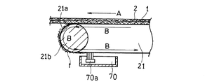
図2は、図1の製造装置においてクリーニングユニット70による繊維くずの除去システムを説明するための概略断面図である。搬送コンベア21では、搬送ローラ21bの回転により搬送ベルト21aが矢印Bの方向(搬送ベルトの移動方向)に移動しており、これに伴い搬送ベルト21aの主面に供給された基材1が矢印Aの方向(基材1の搬送方向)に搬送される。搬送ベルト21aの主面が上向きであるときに、搬送ベルト21aとともに移動する基材1上に繊維が堆積されて、不織布2が形成される。搬送ベルト21aは、基材1の搬送方向Aの下流側に位置する搬送ローラ21bの周面に沿って移動し、この搬送ローラ21bと接触しなくなる位置で主面が下向きになる。一方、この搬送ローラ21bの位置で、搬送ベルト21aから離れた積層物は、搬送方向Aに沿って後続の装置や工程に供される。
(Third step and cleaning unit)
Hereinafter, the third step (and the cleaning unit for removing fiber waste) will be described more specifically.
FIG. 2 is a schematic cross-sectional view for explaining a fiber waste removal system by the
クリーニングユニット70は、搬送ベルト21aの主面に残存していた繊維くずfを除去するための治具としてのブラシ70aを備えている。図2では、クリーニングユニット70は、搬送コンベア21の下方に設置されているが、特にこの場合に限定されず、搬送ベルト21aの移動経路において、基材1および不織布2の積層物が搬送ベルト21aから離れる位置よりも下流であればよい。図2の例では、基材1と不織布2との積層物が搬送ベルト21aから離れた後、搬送ベルト21aの主面が下向きであるときに、搬送ベルト21aの主面の下方に設置されたブラシ70aを、搬送ベルト21aの主面に接触させる。これにより、搬送ベルト21aの主面に残存していた繊維くずfが除去される。
The
図3は、図2において繊維くずfがブラシ70aで除去される様子を模式的に示す側面図である。搬送ベルト21aは、治具としてのブラシ70a(治具の少なくとも繊維くずfを除去する領域(具体的には、ブラシ70aの毛の部分))に対向する端面E1を備える段差S1を有している。図3では、搬送ベルト21aは、少なくとも1つの帯状のベルトの端部同士を重ね合わせて連結することで環状に形成されており、この連結部分に段差S1が形成されている。このとき、ベルトの内周側の端部に重ねられた外周側の端部が内周側の端部の主面よりも外周側に突出した状態となることで、外周側の端部に端面E1が形成されている。なお。搬送コンベアを側面から見たときに、搬送コンベアの中心に近い方を内周側、中心から遠い方を外周側としている。
FIG. 3 is a side view schematically showing how the fiber waste f is removed by the
端面E1は、搬送ベルト21aを移動方向Bに沿って移動させるときに、段差S1の近傍において、ブラシ70aが、端面E1よりも下流側の搬送ベルト21aの主面に接触するとともに、端面E1(または端面E1にかかる繊維くずf)にも接触するように形成される。端面E1は、搬送ベルト21aの移動方向Bから見えるように形成される。つまり、端面E1は、搬送ベルト21aの移動方向Bに向けて形成される。端面E1を、ブラシ70a(具体的には、ブラシ70aの毛の部分)に対向させると、移動方向Bに沿って移動している搬送ベルト21aの端面E1(または端面E1にかかる繊維くずf)に、ブラシ70aをより確実に接触させることができる。繊維くずfは、搬送ベルト21aの主面上において、不織布状に連続して付着しているため、段差S1の部分を起点としてブラシ70aで連続的に擦り取ることができる。このように、本発明では、段差S1を利用して、治具(ブラシ70a)により繊維くずfを容易に除去することができる。
In the end surface E1, when the
なお、段差の端面が治具と対向(または接触)するとは、端面が、治具の少なくとも繊維くずを除去する領域(ブラシの場合には、毛の部分)と対向(または接触)することを意味する。同様に、搬送ベルトの主面が治具と接触するとは、搬送ベルトの主面が、治具の少なくとも繊維くずを除去する領域(ブラシの場合には、毛の部分)と接触することを意味する。 Note that the end face of the step faces (or comes into contact with) the jig means that the end face faces (or comes into contact) with at least the region of the jig that removes fiber waste (the hair part in the case of a brush). means. Similarly, the fact that the main surface of the conveyor belt is in contact with the jig means that the main surface of the conveyor belt is in contact with at least the region of the jig from which fiber waste is removed (the hair part in the case of a brush). To do.
図4〜図7は、それぞれ、搬送ベルトの段差の状態が異なる場合に繊維くずfがブラシ70aで除去される様子を模式的に示す側面図である。図4〜図7は、図3とは段差の状態が異なるだけでその他は図3と同じである。図4〜図7では、図2および図3と同じものには同じ符号を付している。
4 to 7 are side views schematically showing how the fiber waste f is removed by the
図4において、搬送ベルト121aは、搬送ベルト121aの主面に対して傾斜した端面E2を備える段差S2を有している。端面E2は、移動する搬送ベルト121aとブラシ70aが接触する際に、段差S2およびその近傍において、ブラシ70aが、移動方向Bの端面E2よりも下流側で搬送ベルト121aの主面と接触するとともに、端面E2とも接触するように形成される必要がある。そのため、端面E2は、移動方向Bの下流側から上流側に向かって搬送ベルト121aの厚みが増す(段差S2の高さが大きくなる)ように形成され、これにより、端面E2をブラシ70aに対向させる。このような端面E2を有する段差S2を形成することで、移動方向Bに沿って移動している搬送ベルト121aの端面E2に、ブラシ70aをより確実に接触させることができ、繊維くずfを容易に除去することができる。
In FIG. 4, the
図5では、搬送ベルト221aは、ブラシ70aに対向する端面E3を備える段差S3を有する。段差S3は、少なくとも1つの帯状のベルトの端部同士を連結した部分に形成されるが、帯状のベルトの端部同士は、その端面同士が接触するように連結される。このとき、一方の端部の厚みを、この一方の端部と連結される他方の端部の厚みよりも大きくすることで段差S3が形成され、厚みが小さい方の端部よりも厚みが大きい方の端部が外周側に突出することで、端面E3が形成される。端面E3がブラシ70aと対向するように、搬送ベルト221aの移動方向Bにおいて下流側に配されるベルトの端部の厚みを小さく、上流側に配されるベルトの端部の厚みを大きくする。そして、端面E3を備える段差S3を利用することで、搬送ベルト221aの主面に付着した繊維くずfをブラシ70aにより容易に除去することができる。
In FIG. 5, the
図5では、段差S3を形成するために、移動方向Bの端面E3よりも上流側では、移動方向Bに沿って搬送ベルト221aの厚みが大きくなるように、搬送ベルト221aの主面が傾斜した状態となっている。しかし、特にこの場合に限定されない。例えば、移動方向Bの端面E3よりも上流側で搬送ベルト221aの厚みを一定にし、端面E3よりも下流側で端面E3に向かって搬送ベルト221aの厚みが小さくなるように主面を傾斜させることで段差S3を形成してもよい。
In FIG. 5, in order to form the step S3, the main surface of the
図6では、搬送ベルト321aは、環状の基部ベルト321cと、基部ベルト321cを覆う表層ベルト321dとを備える。搬送ベルト321aは、表層ベルト321dが途切れた隙間sを少なくとも1つ有している。隙間sを挟んで、搬送ベルト321aの移動方向Bの下流側では、表層ベルト321dの厚みは小さく、上流側では厚みが大きくなっている。表層ベルト321dの厚みが大きな部分が、隙間sを挟んで、厚みが小さな部分よりも外周側に突出することで、搬送ベルト321aには、端面E4を備える段差S4が形成される。端面E4はブラシ70aに対向しており、移動する搬送ベルト321aにブラシ70aを接触させることで、端面E4を利用して、繊維くずfが除去される。
なお、図6では、隙間を挟んで表層ベルトの厚みが異なる場合を示したが、表層ベルトの厚みは同じであってもよい。
In FIG. 6, the
Although FIG. 6 shows the case where the thickness of the surface belt is different with a gap in between, the thickness of the surface belt may be the same.
図7において、環状の搬送ベルト421aの主面には、搬送ベルト421aの主面から搬送コンベアの外周方向に向かって突出する凸部Pが形成されている。凸部Pが、搬送ベルト421aの主面から突出することで、凸部Pの側面を端面E5とする段差S5が形成される。端面E5は、ブラシ70aに対向するように形成されている。この例においても、ブラシ70aを移動する搬送ベルト421aの主面に接触させると、段差S5の端面E5にも接触して、この段差S5を利用して繊維くずfを除去することができる。
In FIG. 7, a convex portion P is formed on the main surface of the
繊維くずは、段差において連続していてもよく、不連続であってもよい。繊維くずが段差において不連続である場合、治具を段差の端面に接触させたときに、段差を起点として繊維くずを除去し易い。そのため、段差において繊維くずが不連続となるように、段差の高さ、段差の形状や繊維の堆積状態を調節してもよい。なお、段差において繊維くずが不連続とは、段差の端面の部分における繊維くずの分布が、端面を挟む両側の領域における繊維くずの分布に比べて少なくなっている(繊維くずの分布が粗である)状態を言う。例えば、端面にかかる繊維くずの単位面積当たりの量が、端面を挟む両側の領域における繊維くずの単位面積当たりの量の例えば50%以下である場合を繊維くずが不連続であるとしてもよい。なお、単位面積当たりの繊維くずの量は、例えば、走査型電子顕微鏡(SEM)写真に基づいて求めることができる。具体的には、SEM写真において、所定面積の範囲について端面にかかる繊維くずの投影面積を求め、単位面積当たりの繊維くずの面積比を算出する。同様にして端面を挟む両側の領域における繊維くずの単位面積当たりの面積比を算出する。そして、後者の面積比を100%としたときの前者の比率(%)を算出すればよい。 The fiber waste may be continuous at the step or discontinuous. When the fiber waste is discontinuous at the step, it is easy to remove the fiber waste starting from the step when the jig is brought into contact with the end face of the step. Therefore, the height of the step, the shape of the step, and the fiber accumulation state may be adjusted so that the fiber waste is discontinuous at the step. It should be noted that fiber waste is discontinuous at the level difference, where the distribution of fiber waste at the end face of the step is smaller than the fiber waste distribution at both sides of the end face (the fiber waste distribution is coarse. Say state. For example, fiber scraps may be discontinuous when the amount per unit area of fiber scraps on the end face is, for example, 50% or less of the amount per unit area of fiber scraps on both sides of the end face. In addition, the quantity of the fiber waste per unit area can be calculated | required based on a scanning electron microscope (SEM) photograph, for example. Specifically, in the SEM photograph, the projected area of the fiber scraps on the end face in the range of a predetermined area is obtained, and the area ratio of the fiber scraps per unit area is calculated. Similarly, the area ratio per unit area of the fiber waste in the regions on both sides sandwiching the end face is calculated. Then, the former ratio (%) may be calculated when the latter area ratio is 100%.
段差は、搬送ベルトの移動方向と垂直な方向に沿って(垂直な方向全体に)設けてもよく、繊維くずが残存している領域において設けてもよい。搬送ベルト上では、主に基材よりも広い範囲に堆積された繊維が繊維くずとなる。そのため、繊維くずは、搬送ベルトの移動方向と垂直な方向における基材の端部よりも外側において搬送ベルトの主面に残存している。このような観点からは、少なくとも、搬送ベルトの移動方向と垂直な方向の両端部に段差を形成すればよい。搬送ベルトの移動方向と垂直な方向の中央部には、繊維くずはほとんど付着していないため、特に段差を設ける必要はないが、中央部に段差が形成されていてもよい。 The step may be provided along a direction perpendicular to the moving direction of the conveying belt (over the entire vertical direction), or may be provided in a region where fiber waste remains. On the conveyor belt, fibers deposited mainly in a wider area than the base material become fiber scraps. Therefore, the fiber waste remains on the main surface of the transport belt outside the end of the base material in the direction perpendicular to the moving direction of the transport belt. From such a viewpoint, it is only necessary to form steps at both ends in the direction perpendicular to the moving direction of the conveyor belt. Since almost no fiber waste is attached to the central portion in the direction perpendicular to the moving direction of the conveyor belt, it is not necessary to provide a step in particular, but a step may be formed in the central portion.
なお、搬送ベルトの移動方向に垂直な方向の中央部とは、搬送ベルトの移動方向に垂直な方向における中心を含む領域であり、好ましくは前述の両端部の内側の領域を言うものとする。 The central portion in the direction perpendicular to the moving direction of the transport belt is a region including the center in the direction perpendicular to the moving direction of the transport belt, and preferably refers to a region inside the above-described both end portions.
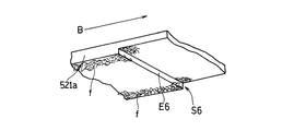
図8〜図10は、搬送ベルトの移動方向と垂直な方向における段差の状態を説明するための概略斜視図である。
図8において搬送ベルト521aは、端面E6を備える段差S6を有しており、端面E6は図示しない治具に対向している。図示例では、段差S6は、搬送ベルト521aの移動方向Bと垂直な方向に沿って搬送ベルト521aの主面を横切るように垂直な方向全体に形成されている。
8 to 10 are schematic perspective views for explaining a state of a step in a direction perpendicular to the moving direction of the conveyor belt.
In FIG. 8, the
図9に示す搬送ベルト621aでは、段差S7は、搬送ベルト621aの移動方向Bと垂直な方向における両端部に形成されており、垂直な方向における中央部には段差は形成されていない。段差S7は、図示しない治具に対向する端面E7を備えている。
In the
図10では、搬送ベルト721aは、図示しない治具に対向する端面E8を備える段差S8を有している。段差S8は、搬送ベルト721aの移動方向Bと垂直な方向に沿って搬送ベルト721aを横切るように全体に形成されている。移動方向Bと垂直な方向の中央部では、段差S8の高さは低くなっており、この中央部の段差S8の高さに比べて、両端部では、段差S8の高さは高くなっている。
In FIG. 10, the
図8〜図10において、繊維くずfは、搬送ベルトの移動方向と垂直な方向の両端部において、搬送ベルトの主面に付着している。搬送ベルトの段差において、端面にかかる繊維くずfはほとんどなく、繊維くずfは不連続となっている。このように、少なくとも繊維くずが付着している領域に段差が形成されていることで、段差の端面に治具を接触させて繊維くずを擦り取ることができる。また、繊維くずfが段差において不連続となっていることで、段差を起点として繊維くずfを除去し易くなる。 8 to 10, the fiber waste f is attached to the main surface of the conveyor belt at both ends in the direction perpendicular to the moving direction of the conveyor belt. At the step of the conveyor belt, there is almost no fiber waste f on the end face, and the fiber waste f is discontinuous. As described above, since the step is formed at least in the region where the fiber scrap is adhered, the jig can be brought into contact with the end face of the step to scrape the fiber scrap. Further, since the fiber waste f is discontinuous at the level difference, the fiber waste f can be easily removed from the level difference.
段差の最大高さは、0.1mm以上であることが好ましく、0.5mm以上であることがさらに好ましい。段差の最大高さは、例えば、5mm以下である。最大高さがこのような範囲となるように段差を形成することで、繊維くずを除去し易くなる。 The maximum height of the step is preferably 0.1 mm or more, and more preferably 0.5 mm or more. The maximum height of the step is, for example, 5 mm or less. By forming the step so that the maximum height falls within such a range, it becomes easy to remove fiber waste.
段差の最大高さが大きくなると、繊維くずを除去し易くなるものの、基材を載置する領域の段差の高さが大きくなると、不織布における繊維の堆積状態がばらつくことになる。そのため、搬送ベルトの移動方向に垂直な方向の中央部では、段差を形成しないか、もしくは段差を形成する場合でも、中央部における段差の高さを移動方向に垂直な方向の両端部の高さよりも小さくすることが好ましい。中央部における段差の高さは、例えば、0.05mm以下であり、0.01mm以下または0.005mm以下とすることが好ましい。 When the maximum height of the step becomes large, it becomes easy to remove fiber waste, but when the height of the step in the region where the base material is placed becomes large, the fiber deposition state on the nonwoven fabric varies. Therefore, in the central part in the direction perpendicular to the moving direction of the conveyor belt, no step is formed, or even when a step is formed, the height of the step in the central part is higher than the height of both ends in the direction perpendicular to the moving direction. It is preferable to reduce the size. The height of the step in the central portion is, for example, 0.05 mm or less, and preferably 0.01 mm or less or 0.005 mm or less.
段差は、端面が搬送ベルトの移動方向に向くように形成すればよい。搬送ベルトの側面から見たときに、段差の端面と、搬送ベルトの移動方向において端面の下流側の搬送ベルトの主面との間に形成される角度は、例えば、70〜140°であり、80〜120°であることが好ましい。
また、段差は、搬送ベルトを上面から見たときに、搬送ベルトの移動方向と垂直な方向に沿って形成されていてもよく、垂直な方向に対して斜めに形成されていてもよい。
What is necessary is just to form a level | step difference so that an end surface may face the moving direction of a conveyance belt. When viewed from the side surface of the conveyance belt, an angle formed between the end surface of the step and the main surface of the conveyance belt on the downstream side of the end surface in the movement direction of the conveyance belt is, for example, 70 to 140 °, It is preferable that it is 80-120 degrees.
Further, the step may be formed along a direction perpendicular to the moving direction of the conveying belt when the conveying belt is viewed from above, or may be formed obliquely with respect to the vertical direction.
環状の搬送ベルトにおいて、段差は少なくとも1箇所に形成すればよく、2箇所以上に形成してもよい。搬送ベルトの移動方向に沿って2箇所以上に段差を形成する場合、繊維くずをさらに除去し易くなる。この場合、少なくとも1箇所の段差の最大高さは、他の箇所の段差の最大高さと異なっていてもよい。なお、段差の端面(治具と対向する端面)同士が同一平面上に存在する場合には、段差は1箇所に形成されているものとする。 In the annular conveying belt, the step may be formed at least at one place, and may be formed at two or more places. When forming a level | step difference in two or more places along the moving direction of a conveyance belt, it becomes still easier to remove fiber waste. In this case, the maximum height of the step in at least one place may be different from the maximum height of the step in other places. When the end faces of the step (end faces facing the jig) are on the same plane, the step is formed at one place.
治具としては、搬送ベルトの主面に接触して繊維くずを除去できればよく、ブラシに限らず、粘着ローラなども利用でき、ブラシと粘着ローラとを併用してもよい。ブラシとしては、必要に応じてロール状のブラシを用いてもよい。
ブラシの毛の材質は、特に制限されないが、搬送ベルトに傷がつき難い観点からは、植物繊維や動物繊維などの天然繊維や、樹脂などで形成された化学繊維などが好ましい。
The jig is not limited to a brush as long as it can contact the main surface of the conveyor belt and remove fiber waste. An adhesive roller or the like can also be used, and a brush and an adhesive roller may be used in combination. As a brush, you may use a roll-shaped brush as needed.
The material of the bristles of the brush is not particularly limited, but natural fibers such as plant fibers and animal fibers, chemical fibers formed of resin, and the like are preferable from the viewpoint that the conveyance belt is not easily damaged.
治具としてブラシを用いる場合には、段差の最大高さ(特に、搬送ベルトの移動方向と垂直な方向の両端部における段差)よりも、ブラシの毛の平均線径を小さくすることが好ましい。この場合、段差の端面や段差の隅部(段差の端面と、この端面の搬送ベルトの移動方向の下流側における搬送ベルトの主面との間に形成される隅部)にブラシの毛が接触し易くなり、繊維くずの除去性を高めることができる。ブラシの毛の平均線径は、例えば、1〜300μmの範囲から適宜選択でき、1〜80μmまたは10〜50μmであってもよい。 When a brush is used as the jig, it is preferable to make the average wire diameter of the brush bristles smaller than the maximum height of the step (particularly, the step at both ends in the direction perpendicular to the moving direction of the transport belt). In this case, the brush bristles contact the end surface of the step or the corner of the step (the corner formed between the end surface of the step and the main surface of the transport belt on the downstream side in the moving direction of the transport belt). It becomes easy to do and can improve the removal property of fiber waste. The average wire diameter of the brush hair can be appropriately selected from the range of 1 to 300 μm, for example, and may be 1 to 80 μm or 10 to 50 μm.
第3工程(またはクリーニングユニット)において使用される治具の個数は特に制限されず、1つであってもよく、複数であってもよい。複数の治具を用いる場合、治具は、搬送ベルトの移動方向と垂直な方向に沿って、複数の治具を配置してもよく、搬送ベルトの移動経路に沿って間隔をあけて複数の治具を配置してもよい。また、搬送ベルトの移動方向と垂直な方向に沿う複数(例えば、一対)の治具を、搬送ベルトの移動経路に沿って間隔をあけて複数箇所に(複数対)配置してもよい。搬送ベルトの移動経路に沿って複数箇所に治具を配置する場合、搬送ベルトに付着した繊維くずの除去性をさらに高めることができる。 The number of jigs used in the third step (or cleaning unit) is not particularly limited, and may be one or plural. In the case of using a plurality of jigs, the jig may be arranged along a direction perpendicular to the moving direction of the transport belt, and a plurality of jigs may be arranged at intervals along the transport path of the transport belt. A jig may be arranged. Further, a plurality of (for example, a pair) jigs along a direction perpendicular to the moving direction of the transport belt may be arranged at a plurality of locations (a plurality of pairs) at intervals along the transport path of the transport belt. When the jigs are arranged at a plurality of locations along the movement path of the conveyance belt, it is possible to further improve the removal property of the fiber waste adhering to the conveyance belt.
第3工程において、移動する搬送ベルトの主面に治具を接触させるため、治具自体は、特に移動させる必要はないが、必要に応じて移動させてもよい。治具を移動させる場合、段差を利用して繊維くずを除去できるように、搬送ベルトの移動方向と対向するように移動させることが好ましい。例えば、粘着ローラやロール状のブラシを治具として用いる場合には、搬送ベルトの移動方向とは反対方向に回転させる。 In the third step, since the jig is brought into contact with the main surface of the moving conveyor belt, the jig itself need not be moved, but may be moved as necessary. When the jig is moved, it is preferable to move the jig so as to face the moving direction of the conveyor belt so that the fiber waste can be removed using the step. For example, when an adhesive roller or a roll-like brush is used as a jig, it is rotated in a direction opposite to the moving direction of the conveyor belt.
以下に本発明に係る製造方法の第3工程以外の各工程および製造装置についてより具体的に説明する。
(第1工程)
第1工程では、繊維を生成させ、生成した繊維を堆積させることにより不織布を形成できる限り特に制限されず、公知の紡糸方法などが採用できる。例えば、繊維の原料を溶解させて、溶融紡糸により繊維を生成させ、冷却しながら堆積させることで、不織布を形成してもよい。
Hereinafter, each process and manufacturing apparatus other than the third process of the manufacturing method according to the present invention will be described more specifically.
(First step)
The first step is not particularly limited as long as a nonwoven fabric can be formed by generating fibers and depositing the generated fibers, and a known spinning method can be employed. For example, the non-woven fabric may be formed by dissolving fiber raw materials, generating fibers by melt spinning, and depositing while cooling.
好ましい実施形態では、電界紡糸法により不織布を形成させる。この場合、繊維形成空間において、電界紡糸により繊維を生成させ、生成した繊維を搬送ベルトの主面に供給された基材に堆積させて不織布を形成する。繊維は、繊維の原料を含む原料液を電界紡糸することにより生成させる。電界紡糸では、原料液に高電圧を印加し、電荷をもった原料液をノズルから吐出することにより、繊維が生成する。第1工程では、基材(具体的には、基材の搬送ベルトとは反対側の主面)に不織布が積層された積層物が得られる。 In a preferred embodiment, the nonwoven fabric is formed by electrospinning. In this case, in the fiber forming space, fibers are generated by electrospinning, and the generated fibers are deposited on the base material supplied to the main surface of the transport belt to form a nonwoven fabric. The fiber is produced by electrospinning a raw material liquid containing the raw material of the fiber. In electrospinning, fibers are generated by applying a high voltage to a raw material liquid and discharging the charged raw material liquid from a nozzle. In the first step, a laminate is obtained in which a nonwoven fabric is laminated on a base material (specifically, the main surface of the base material opposite to the conveyor belt).
繊維の原料としては、特に限定されず、紡糸方法に応じて、繊維化可能な各種ポリマーが使用できる。このようなポリマーとしては、例えば、ポリアミド(PA)、ポリイミド(PI)、ポリアミドイミド、ポリエーテルイミド、ポリアセタール、ポリカーボネート、ポリエーテルエーテルケトン、ポリサルフォン、ポリエーテルサルフォン、ポリフェニレンサルファイド、ポリテトラフルオロエチレン、ポリアリレート、ポリアクリロニトリル、ポリフッ化ビニリデン、ポリスチレン(PS)、ポリビニルアルコール、ポリ酢酸ビニル、ポリプロピレン(PP)、ポリエチレンテレフタレート(PET)、ポリウレタン(PU)等のポリマーが挙げられる。これらのポリマーには、それぞれ、単独重合体および共重合体の双方が含まれる。これらのポリマーは電界紡糸法により不織布を形成する場合にも原料として適している。また、繊維の原料として、これらのポリマーの前駆体を用いてもよい。例えば、繊維をPIで構成する場合には、ポリアミド酸などのPI前駆体を原料として用いてもよい。繊維は、これらのポリマーを一種含んでもよく、二種以上含んでもよい。ポリマーは、不織布の用途に応じて適宜選択できる。 The raw material of the fiber is not particularly limited, and various polymers that can be fiberized can be used depending on the spinning method. Examples of such a polymer include polyamide (PA), polyimide (PI), polyamideimide, polyetherimide, polyacetal, polycarbonate, polyetheretherketone, polysulfone, polyethersulfone, polyphenylene sulfide, polytetrafluoroethylene, Examples thereof include polymers such as polyarylate, polyacrylonitrile, polyvinylidene fluoride, polystyrene (PS), polyvinyl alcohol, polyvinyl acetate, polypropylene (PP), polyethylene terephthalate (PET), and polyurethane (PU). Each of these polymers includes both homopolymers and copolymers. These polymers are also suitable as raw materials when forming nonwoven fabrics by electrospinning. Moreover, you may use the precursor of these polymers as a raw material of a fiber. For example, when the fiber is composed of PI, a PI precursor such as polyamic acid may be used as a raw material. The fiber may contain one or more of these polymers. A polymer can be suitably selected according to the use of a nonwoven fabric.
電界紡糸法で使用される原料液は、繊維の原料に加え、通常、溶媒を含む。溶媒としては、繊維の原料を溶解し、揮発などにより除去可能なものであれば特に制限されず、原料の種類や製造条件に応じて、水および有機溶媒から適宜選択して使用できる。溶媒としては、非プロトン性の極性有機溶媒が好ましい。このような溶媒としては、例えば、N,N−ジメチルホルムアミド(DMF)、N,N−ジメチルアセトアミド(DMAc)、N−メチル−2−ピロリドン(NMP)などのアミド(鎖状または環状アミドなど);ジメチルスルホキシドなどのスルホキシドなどが挙げられる。これらの溶媒は一種を単独で用いてもよく、二種以上を組み合わせて用いてもよい。PSやPUなどの原料を溶解し易く、電界紡糸し易い観点からは、DMAc、DMFなどのアミドが好ましい。
原料液は、必要に応じて、公知の添加剤を含むことができる。
The raw material liquid used in the electrospinning method usually contains a solvent in addition to the fiber raw material. The solvent is not particularly limited as long as it dissolves the fiber raw material and can be removed by volatilization or the like, and can be appropriately selected from water and an organic solvent according to the type of raw material and production conditions. As the solvent, an aprotic polar organic solvent is preferable. Examples of such a solvent include amides such as N, N-dimethylformamide (DMF), N, N-dimethylacetamide (DMAc), and N-methyl-2-pyrrolidone (NMP) (chain or cyclic amide). A sulfoxide such as dimethyl sulfoxide; These solvent may be used individually by 1 type, and may be used in combination of 2 or more type. From the viewpoint of easy dissolution of raw materials such as PS and PU and ease of electrospinning, amides such as DMAc and DMF are preferred.
A raw material liquid can contain a well-known additive as needed.
第1工程により得られる繊維の平均繊維径は特に制限されず、例えば、10nm〜3μmの範囲から適宜選択できる。繊維がナノファイバである場合には、特に、搬送ベルトに付着した繊維くずを除去し難い。本発明に係る不織布の製造方法によれば、繊維がナノファイバである場合でも、繊維を容易に除去することができる。ナノファイバの平均繊維径は、例えば、10〜800nmであることが好ましい。 The average fiber diameter of the fiber obtained by the first step is not particularly limited, and can be appropriately selected from a range of 10 nm to 3 μm, for example. When the fibers are nanofibers, it is particularly difficult to remove fiber waste adhering to the conveyance belt. According to the method for producing a nonwoven fabric according to the present invention, even when the fiber is a nanofiber, the fiber can be easily removed. The average fiber diameter of the nanofibers is preferably 10 to 800 nm, for example.
繊維を堆積させる基材としては、特に制限されず、不織布の用途に応じて、樹脂フィルムなどを用いてもよく、不織布(第2不織布)などの多孔質基材を用いてもよい。樹脂フィルムや多孔質基材を構成する樹脂としては、特に制限されず、アクリル樹脂、ポリオレフィン、ポリエステル、PAなどが挙げられる。また、多孔質基材には、セルロースも使用できる。ポリオレフィンとしては、PP、ポリエチレンなどが例示される。ポリエステルとしては、例えば、PET、ポリブチレンテレフタレートなどが挙げられる。また、多孔質基材は、ガラス繊維などの無機繊維で構成してもよい。基材は、これらの材質を一種含んでもよく、二種以上含んでもよい。 The substrate on which the fibers are deposited is not particularly limited, and a resin film or the like may be used depending on the use of the nonwoven fabric, or a porous substrate such as a nonwoven fabric (second nonwoven fabric) may be used. The resin constituting the resin film or the porous substrate is not particularly limited, and examples thereof include acrylic resin, polyolefin, polyester, and PA. Cellulose can also be used for the porous substrate. Examples of polyolefin include PP and polyethylene. Examples of the polyester include PET and polybutylene terephthalate. The porous substrate may be composed of inorganic fibers such as glass fibers. The base material may contain one or more of these materials.
第1工程では、製造ラインの上流から下流に向かって基材が搬送されるように、搬送ベルトを作動させ、搬送ベルトの移動する主面に対して基材を供給する。基材の形状は特に制限されず、シート状であればよいが、帯状であることが好ましい。帯状の基材を、基材の長さ方向が、搬送ベルトが基材を搬送する方向に沿うように搬送ベルトの主面上に供給する。
なお、原料液や基材は、それぞれ第1工程に先立って準備してもよい。
In the first step, the conveyor belt is operated so that the substrate is conveyed from the upstream to the downstream of the production line, and the substrate is supplied to the main surface on which the conveyor belt moves. The shape of the substrate is not particularly limited and may be a sheet shape, but is preferably a belt shape. The belt-like base material is supplied onto the main surface of the transport belt so that the length direction of the base material is along the direction in which the transport belt transports the base material.
In addition, you may prepare a raw material liquid and a base material respectively prior to a 1st process.
(第2工程)
第2工程では、第1工程で形成された基材と不織布との積層物を搬送ベルトから離す。
第2工程で積層物を離した後の搬送ベルトには、基材より外側の領域に堆積された繊維が繊維くずとして残存しており、この繊維くずを第3工程において除去する。
(Second step)
In the second step, the laminate of the base material and the nonwoven fabric formed in the first step is separated from the transport belt.
The fibers deposited in the region outside the base material remain as fiber waste on the transport belt after the laminate is separated in the second step, and the fiber waste is removed in the third step.
第2工程において、搬送ベルトから離された積層物は、そのまま回収してもよく、必要に応じて、乾燥工程(または加熱工程)、接着剤付与工程、圧着工程や保護層を積層する工程などに供した後に、回収してもよい。なお、基材として、離型性を有するシートを用いる場合には、形成された不織布から基材を剥離させてもよい。製造方法がこれらの工程を含む場合、不織布の製造装置は、各工程に対応するユニット、具体的には、乾燥ユニット(または加熱ユニット)、基材や不織布に接着剤を付与する接着剤付与部、基材と不織布とを含む積層物を圧着させる圧着部、保護層積層装置、および/または基材剥離ユニットなどを備えている。 In the second step, the laminate separated from the conveyor belt may be recovered as it is, and if necessary, a drying step (or heating step), an adhesive application step, a pressure bonding step, a step of laminating a protective layer, and the like. You may collect | recover, after using for. In addition, when using the sheet | seat which has a mold release property as a base material, you may peel a base material from the formed nonwoven fabric. When the manufacturing method includes these steps, the nonwoven fabric manufacturing apparatus is a unit corresponding to each step, specifically, a drying unit (or heating unit), an adhesive application unit that applies an adhesive to a substrate or a nonwoven fabric. , A pressure-bonding part for pressure-bonding a laminate including the base material and the nonwoven fabric, a protective layer laminating device, and / or a base material peeling unit.
本発明によれば、搬送ベルト上に繊維を堆積させて不織布を形成する際に、搬送ベルトに付着した繊維くずを容易に除去することができる。そのため、電界紡糸法を利用する不織布製造方法など、様々な不織布の製造方法および製造装置に利用することができる。 ADVANTAGE OF THE INVENTION According to this invention, when depositing a fiber on a conveyance belt and forming a nonwoven fabric, the fiber waste adhering to a conveyance belt can be removed easily. Therefore, it can utilize for the manufacturing method and manufacturing apparatus of various nonwoven fabrics, such as the nonwoven fabric manufacturing method using an electrospinning method.
1:基材、2F:繊維、2:不織布、3:保護層、4:接着剤、10:積層不織布、11、21b、31、41:搬送ローラ、12:供給リール、13、43、53:モータ、21:搬送コンベア、21a、121a、221a、321a、421a、521a、621a、721a:搬送ベルト、321c:基部ベルト、321d:表層ベルト、22:原料液、23:放出体、24:第1支持体、25:第2支持体、26:電圧印加装置、27:対電極、28:ポンプ、29:原料液タンク、32:接着剤タンク、33:ノズル、34:アプリケータ、42:リール、51、52:加圧ローラ、70:クリーニングユニット、70a:ブラシ、A:基材の搬送方向、B:搬送ベルトの移動方向、f:繊維くず、S1〜S8:段差、E1〜E8:端面、s:隙間、P:凸部、200:製造装置(製造システム)、201:基材供給部、202:電界紡糸装置、203:接着剤付与部、204:保護層積層装置、205:圧着部、206:回収装置
1: base material, 2F: fiber, 2: non-woven fabric, 3: protective layer, 4: adhesive, 10: laminated non-woven fabric, 11, 21b, 31, 41: transport roller, 12: supply reel, 13, 43, 53: Motor, 21: Conveyor, 21a, 121a, 221a, 321a, 421a, 521a, 621a, 721a: Conveyor belt, 321c: Base belt, 321d: Surface belt, 22: Raw material liquid, 23: Ejector, 24: First Support: 25: Second support, 26: Voltage application device, 27: Counter electrode, 28: Pump, 29: Raw material tank, 32: Adhesive tank, 33: Nozzle, 34: Applicator, 42: Reel, 51, 52: Pressure roller, 70: Cleaning unit, 70a: Brush, A: Substrate transport direction, B: Transport belt movement direction, f: Textile waste, S1 to S8: Step, E1 to E : End face, s: gap, P: convex part, 200: manufacturing apparatus (manufacturing system), 201: base material supply part, 202: electrospinning apparatus, 203: adhesive application part, 204: protective layer laminating apparatus, 205: Crimping part 206: Collection device
Claims (10)
繊維を生成させ、生成した前記繊維を、環状の搬送ベルトの主面に供給された基材に堆積させて不織布を形成する第1工程と、
前記不織布を前記基材とともに、前記搬送ベルトから離す第2工程と、
前記搬送ベルトに残存する繊維くずを治具により除去する第3工程と、を備え、
前記搬送ベルトの主面は、前記治具と対向する端面を備える段差を有しており、
前記段差は、少なくとも前記搬送ベルトの移動方向と垂直な方向の両端部に形成されており、
前記第3工程において、前記搬送ベルトの主面および前記段差の端面と前記治具とを接触させて前記繊維くずを除去する、不織布の製造方法。 A method for producing a nonwoven fabric containing fibers, comprising:
A first step of generating a fiber, and depositing the generated fiber on a base material supplied to a main surface of an annular conveyance belt to form a nonwoven fabric;
A second step of separating the nonwoven fabric together with the base material from the transport belt;
A third step of removing fiber waste remaining on the conveyor belt with a jig,
The main surface of the conveyor belt has a step having an end surface facing the jig,
The step is formed at least at both ends in a direction perpendicular to the moving direction of the conveyor belt,
The manufacturing method of the nonwoven fabric which makes the main surface of the said conveyance belt, the end surface of the said level | step difference, and the said jig | tool in the said 3rd process, and removes the said fiber waste.
前記中央部における前記段差の高さは、前記両端部における前記段差の高さより小さい請求項1または2に記載の不織布の製造方法。 The main surface of the conveyor belt has the step in the central portion in the direction perpendicular to the moving direction of the conveyor belt,
The height of the said level | step difference in the said center part is a manufacturing method of the nonwoven fabric of Claim 1 or 2 smaller than the height of the said level | step difference in the said both ends.
繊維を生成させ、前記繊維を前記基材に堆積させて不織布を形成する紡糸機構と、
前記不織布および前記基材が前記搬送ベルトから離れた後、前記搬送ベルトに残存する繊維くずを除去する治具と、を備え、
前記搬送ベルトの主面は、前記治具と対向する端面を備える段差を有しており、
前記段差は、少なくとも前記搬送ベルトの移動方向と垂直な方向の両端部に形成されており、
前記繊維くずは、前記治具と、前記搬送ベルトの主面および前記段差の端面とを接触させることで除去される、不織布の製造装置。
A base material supply unit for supplying the base material to the main surface of the annular conveying belt;
A spinning mechanism for generating fibers and depositing the fibers on the substrate to form a nonwoven fabric;
A jig for removing fiber waste remaining on the conveyor belt after the nonwoven fabric and the substrate are separated from the conveyor belt,
The main surface of the conveyor belt has a step having an end surface facing the jig,
The step is formed at least at both ends in a direction perpendicular to the moving direction of the conveyor belt,
The said waste fiber is a nonwoven fabric manufacturing apparatus removed by making the said jig | tool contact the main surface of the said conveyance belt, and the end surface of the said level | step difference.
Priority Applications (1)
| Application Number | Priority Date | Filing Date | Title |
|---|---|---|---|
| JP2016040479A JP6611049B2 (en) | 2016-03-02 | 2016-03-02 | Nonwoven fabric manufacturing method and manufacturing apparatus |
Applications Claiming Priority (1)
| Application Number | Priority Date | Filing Date | Title |
|---|---|---|---|
| JP2016040479A JP6611049B2 (en) | 2016-03-02 | 2016-03-02 | Nonwoven fabric manufacturing method and manufacturing apparatus |
Publications (2)
| Publication Number | Publication Date |
|---|---|
| JP2017155367A true JP2017155367A (en) | 2017-09-07 |
| JP6611049B2 JP6611049B2 (en) | 2019-11-27 |
Family
ID=59808204
Family Applications (1)
| Application Number | Title | Priority Date | Filing Date |
|---|---|---|---|
| JP2016040479A Active JP6611049B2 (en) | 2016-03-02 | 2016-03-02 | Nonwoven fabric manufacturing method and manufacturing apparatus |
Country Status (1)
| Country | Link |
|---|---|
| JP (1) | JP6611049B2 (en) |
Cited By (1)
| Publication number | Priority date | Publication date | Assignee | Title |
|---|---|---|---|---|
| CN113308824A (en) * | 2021-05-27 | 2021-08-27 | 莆田市朝之辉电子商务有限公司 | Sanitary towel raw materials washing equipment |
Families Citing this family (1)
| Publication number | Priority date | Publication date | Assignee | Title |
|---|---|---|---|---|
| KR102650274B1 (en) * | 2021-12-13 | 2024-03-22 | (주)씨앤투스 | Flash―Spun Apparatus with Air Curtain and Method thereof |
-
2016
- 2016-03-02 JP JP2016040479A patent/JP6611049B2/en active Active
Cited By (2)
| Publication number | Priority date | Publication date | Assignee | Title |
|---|---|---|---|---|
| CN113308824A (en) * | 2021-05-27 | 2021-08-27 | 莆田市朝之辉电子商务有限公司 | Sanitary towel raw materials washing equipment |
| CN113308824B (en) * | 2021-05-27 | 2023-08-11 | 莆田市朝之辉电子商务有限公司 | Sanitary towel raw material washing equipment |
Also Published As
| Publication number | Publication date |
|---|---|
| JP6611049B2 (en) | 2019-11-27 |
Similar Documents
| Publication | Publication Date | Title |
|---|---|---|
| CN107619818B (en) | Method and apparatus for producing culture medium | |
| CN106811869B (en) | Laminated nonwoven fabric | |
| JP5798399B2 (en) | BAG FILTER FILTER, BAG FILTER FILTER MANUFACTURING METHOD AND BAG FILTER | |
| JP6569983B2 (en) | Laminated nonwoven fabric and method for producing laminated nonwoven fabric | |
| JP6528246B2 (en) | FIBER LAMINATE AND METHOD FOR MANUFACTURING THE SAME | |
| JP6624589B2 (en) | Manufacturing method of laminated nonwoven fabric | |
| CN106808743B (en) | Laminated nonwoven fabric and method for producing same | |
| JP2017155366A (en) | Manufacturing method and manufacturing installation of non-woven fabric | |
| JP6611049B2 (en) | Nonwoven fabric manufacturing method and manufacturing apparatus | |
| JP2017197872A (en) | Laminate, and method and device for manufacturing the same | |
| KR20180002675A (en) | Filter element and filter unit | |
| JP5883614B2 (en) | Method for producing nanofiber laminate | |
| CN107012586B (en) | Nonwoven fabric, dust collecting filter provided with same, culture medium for microorganisms or biological tissues, and cosmetic | |
| CN106400303B (en) | Laminated nonwoven fabric and air cleaner | |
| JP6508630B2 (en) | Equipment for manufacturing laminated nonwoven fabric | |
| US10173158B2 (en) | Laminated nonwoven fabric, air purifier, and manufacturing method of laminated nonwoven fabric | |
| JP2017197874A (en) | Laminate, and method and device for manufacturing the same | |
| JP6624586B2 (en) | Manufacturing method and manufacturing apparatus for laminate | |
| CN107020776B (en) | Laminate and method for producing same | |
| JP2018059225A (en) | Method for manufacturing fiber structure | |
| JP6464486B2 (en) | Laminate manufacturing method and manufacturing apparatus | |
| JP6464487B2 (en) | Laminate manufacturing method and manufacturing apparatus | |
| JP2017197873A (en) | Method and device for manufacturing laminate | |
| JP2017052195A (en) | Method and apparatus for producing laminate | |
| JP2017197876A (en) | Method and device for manufacturing laminate |
Legal Events
| Date | Code | Title | Description |
|---|---|---|---|
| RD02 | Notification of acceptance of power of attorney |
Free format text: JAPANESE INTERMEDIATE CODE: A7422 Effective date: 20180709 |
|
| A621 | Written request for application examination |
Free format text: JAPANESE INTERMEDIATE CODE: A621 Effective date: 20181212 |
|
| A977 | Report on retrieval |
Free format text: JAPANESE INTERMEDIATE CODE: A971007 Effective date: 20190920 |
|
| TRDD | Decision of grant or rejection written | ||
| A01 | Written decision to grant a patent or to grant a registration (utility model) |
Free format text: JAPANESE INTERMEDIATE CODE: A01 Effective date: 20191001 |
|
| A61 | First payment of annual fees (during grant procedure) |
Free format text: JAPANESE INTERMEDIATE CODE: A61 Effective date: 20191018 |
|
| R151 | Written notification of patent or utility model registration |
Ref document number: 6611049 Country of ref document: JP Free format text: JAPANESE INTERMEDIATE CODE: R151 |