JP2017152165A - Power storage device - Google Patents
Power storage device Download PDFInfo
- Publication number
- JP2017152165A JP2017152165A JP2016032547A JP2016032547A JP2017152165A JP 2017152165 A JP2017152165 A JP 2017152165A JP 2016032547 A JP2016032547 A JP 2016032547A JP 2016032547 A JP2016032547 A JP 2016032547A JP 2017152165 A JP2017152165 A JP 2017152165A
- Authority
- JP
- Japan
- Prior art keywords
- protrusion
- exterior body
- power storage
- peripheral edge
- storage device
- Prior art date
- Legal status (The legal status is an assumption and is not a legal conclusion. Google has not performed a legal analysis and makes no representation as to the accuracy of the status listed.)
- Granted
Links
Images


Classifications
-
- Y—GENERAL TAGGING OF NEW TECHNOLOGICAL DEVELOPMENTS; GENERAL TAGGING OF CROSS-SECTIONAL TECHNOLOGIES SPANNING OVER SEVERAL SECTIONS OF THE IPC; TECHNICAL SUBJECTS COVERED BY FORMER USPC CROSS-REFERENCE ART COLLECTIONS [XRACs] AND DIGESTS
- Y02—TECHNOLOGIES OR APPLICATIONS FOR MITIGATION OR ADAPTATION AGAINST CLIMATE CHANGE
- Y02E—REDUCTION OF GREENHOUSE GAS [GHG] EMISSIONS, RELATED TO ENERGY GENERATION, TRANSMISSION OR DISTRIBUTION
- Y02E60/00—Enabling technologies; Technologies with a potential or indirect contribution to GHG emissions mitigation
- Y02E60/10—Energy storage using batteries
Landscapes
- Sealing Battery Cases Or Jackets (AREA)
- Battery Mounting, Suspending (AREA)
- Electric Double-Layer Capacitors Or The Like (AREA)
Abstract
Description
本発明は、蓄電素子と、外装体とを備える蓄電装置に関する。 The present invention relates to a power storage device including a power storage element and an exterior body.
従来、外装体内に、複数の蓄電素子を収容した蓄電装置が知られている(例えば特許文献1参照)。外装体は、開口を有する容器本体である第一外装体と、蓋体である第二外装体とを有しており、第一外装体に複数の蓄電素子を収容してから、第二外装体で第一外装体の開口を密閉するようになっている。 Conventionally, a power storage device in which a plurality of power storage elements are housed in an exterior body is known (see, for example, Patent Document 1). The exterior body includes a first exterior body that is a container body having an opening and a second exterior body that is a lid body, and a plurality of power storage elements are accommodated in the first exterior body, and then the second exterior body The body is configured to seal the opening of the first exterior body.
ところで、第一外装体と第二外装体とを固定するために接着剤が用いられる場合があるが、その接着剤が硬化する前に第一外装体の外側面に垂れて外部に露出して、蓄電装置自体の見栄えを損ねるおそれがあった。 By the way, an adhesive may be used to fix the first exterior body and the second exterior body, but before the adhesive is cured, it hangs down on the outer surface of the first exterior body and is exposed to the outside. There is a risk of deteriorating the appearance of the power storage device itself.
このため、本発明の目的は、第一外装体と第二外装体とを接着固定するための接着剤が蓄電装置の外観を損ねることを抑制することである。 For this reason, an object of the present invention is to prevent the adhesive for bonding and fixing the first exterior body and the second exterior body from deteriorating the appearance of the power storage device.
上記目的を達成するために、本発明の一態様に係る蓄電装置は、蓄電素子と外装体とを備える蓄電装置であって、外装体は、第一外装体と、第一外装体の上方に配置された第二外装体とを備え、第一外装体は、上方に向かって開放した第一開口をなす第一周縁部を有し、第二外装体は、下方に向かって開放した第二開口をなし、第一周縁部に対して外方から対向する第二周縁部を有し、第一周縁部の上端面と、第二外装体とが接着剤により接着されており、第一周縁部における第二周縁部と対向する外側面と、第二周縁部における第一周縁部に対向する内側面との少なくとも一方には、他方に向けて突出する突起が形成されている。 In order to achieve the above object, a power storage device according to one embodiment of the present invention is a power storage device including a power storage element and an exterior body, and the exterior body is located above the first exterior body and the first exterior body. A first exterior body having a first peripheral edge that forms a first opening opened upward, and the second exterior body is a second exterior opened downward. It has an opening and has a second peripheral edge that faces the first peripheral edge from the outside, and the upper end surface of the first peripheral edge and the second exterior body are bonded by an adhesive, and the first peripheral edge A protrusion projecting toward the other is formed on at least one of the outer surface facing the second peripheral edge of the portion and the inner surface facing the first peripheral edge of the second peripheral edge.
これによれば、第一周縁部における第二周縁部と対向する外側面と、第二周縁部における第一周縁部に対向する内側面との少なくとも一方には、他方に向けて突出する突起が形成されているので、接着剤が第一周縁部の上端面から溢れたとしても、突起から下方に垂れることを抑制することができる。 According to this, at least one of the outer surface facing the second peripheral edge in the first peripheral edge and the inner surface facing the first peripheral edge in the second peripheral edge has a protrusion protruding toward the other. Since it is formed, even if the adhesive overflows from the upper end surface of the first peripheral edge, it is possible to prevent the adhesive from drooping downward.
また、第二周縁部が第一周縁部よりも外方に配置されているので、突起より上の接着剤を覆い隠すことができ、蓄電装置自体の外観性を高めることができる。 In addition, since the second peripheral edge portion is disposed outward from the first peripheral edge portion, the adhesive above the protrusion can be covered and the appearance of the power storage device itself can be improved.
また、第一周縁部の外側面には、突起である第一突起が形成されており、第二周縁部は、第一突起よりも下方に延びるスカート部を含み、スカート部の内側面には、第一突起の下面に対向する第二突起が突起として形成されてもよい。 In addition, a first protrusion that is a protrusion is formed on the outer surface of the first peripheral edge, and the second peripheral edge includes a skirt that extends downward from the first protrusion, and the inner surface of the skirt has The second protrusion facing the lower surface of the first protrusion may be formed as a protrusion.
これによれば、第一外装体の第一周縁部の外側面には、第一突起が形成されているので、接着剤が第一周縁部の上端面から溢れたとしても、第一突起から下方に垂れることを抑制することができる。また、スカート部が第一突起よりも下方に伸びており、さらにスカート部には第一突起の下面に対向する第二突起が形成されているので、第一突起に付着した接着剤をスカート部で隠すことができる。したがって、蓄電装置の外観からは接着剤が露出しにくくなり、蓄電装置自体の外観性を高めることができる。 According to this, since the first protrusion is formed on the outer side surface of the first peripheral portion of the first exterior body, even if the adhesive overflows from the upper end surface of the first peripheral portion, the first protrusion It is possible to suppress drooping downward. Further, since the skirt portion extends downward from the first protrusion, and the second protrusion is formed on the skirt portion so as to face the lower surface of the first protrusion, the adhesive attached to the first protrusion is applied to the skirt portion. Can be hidden. Therefore, the adhesive is hardly exposed from the appearance of the power storage device, and the appearance of the power storage device itself can be improved.
また、第一突起の下面に対向する第二突起が設けられているので、第二外装体が第一外装体から浮こうとしても、第二突起が第一突起に当接し、浮きが抑制される。これにより、接着後に高い防水性を確保することができる。 In addition, since the second protrusion is provided opposite to the lower surface of the first protrusion, even if the second exterior body tries to float from the first exterior body, the second protrusion comes into contact with the first protrusion and the floating is suppressed. The Thereby, high waterproofness is securable after adhesion | attachment.
また、第一周縁部の外側面には、突起である第三突起が形成されており、第二周縁部の内側面には、第三突起の上面に当接する第四突起が突起として形成されており、第二周縁部は、第三突起よりも下方に延びるスカート部を含んでもよい。 A third protrusion, which is a protrusion, is formed on the outer surface of the first peripheral edge, and a fourth protrusion that is in contact with the upper surface of the third protrusion is formed as a protrusion on the inner surface of the second peripheral edge. The second peripheral edge portion may include a skirt portion extending downward from the third protrusion.
これによれば、第一外装体の第一周縁部の外側面には、第三突起が形成されているので、接着剤が第一周縁部の上端面から溢れたとしても、第三突起から下方に垂れることを抑制することができる。また、第二外装体においては、第三突起の上面に当接する第四突起よりもスカート部が下方に伸びているので、第三突起がスカート部により覆われる。これにより、第三突起に付着した接着剤をスカート部で隠すことができる。したがって、蓄電装置の外観からは接着剤が露出しにくくなり、蓄電装置自体の外観性を高めることができる。 According to this, since the third protrusion is formed on the outer peripheral surface of the first peripheral portion of the first exterior body, even if the adhesive overflows from the upper end surface of the first peripheral portion, the third protrusion It is possible to suppress drooping downward. Further, in the second exterior body, the skirt portion extends downward from the fourth projection abutting on the upper surface of the third projection, so that the third projection is covered by the skirt portion. Thereby, the adhesive agent adhering to the third protrusion can be hidden by the skirt portion. Therefore, the adhesive is hardly exposed from the appearance of the power storage device, and the appearance of the power storage device itself can be improved.
また、第四突起が、第三突起の上面に当接することにより第二外装体の下方への移動を規制するので、第一外装体に対する第二外装体の位置を合わせることができ、スムーズに組み立てを行うことができる。 In addition, since the fourth protrusion is in contact with the upper surface of the third protrusion and restricts the downward movement of the second exterior body, the position of the second exterior body relative to the first exterior body can be aligned and smoothly Assembly can be performed.
また、第四突起に第三突起が当接した状態の第二外装体と、第一外装体の第一周縁部の上端面との間には、接着剤を収容する隙間が形成されていてもよい。 In addition, a gap for accommodating an adhesive is formed between the second exterior body in a state where the third protrusion is in contact with the fourth protrusion and the upper end surface of the first peripheral edge of the first exterior body. Also good.
これによれば、第四突起によって下方への移動を規制された第二外装体と、第一周縁部の上端面との間には、接着剤を収容する隙間が積極的に形成されているので、この隙間内で接着剤を保持することができる。したがって、第一外装体と第二外装体との接着強度を安定させることができる。 According to this, the clearance gap which accommodates an adhesive agent is positively formed between the 2nd exterior body by which the downward movement was controlled by the 4th protrusion, and the upper end surface of a 1st peripheral part. Therefore, the adhesive can be held in this gap. Therefore, the adhesive strength between the first exterior body and the second exterior body can be stabilized.
また、第一周縁部の外側面には、第一突起と、当該第一突起とは異なる突起である第三突起とが水平方向に並んで配置されており、第二周縁部の内側面には、第三突起の上面に当接する第四突起が配置されていてもよい。 In addition, a first protrusion and a third protrusion, which is a protrusion different from the first protrusion, are arranged in a horizontal direction on the outer surface of the first peripheral edge, and are arranged on the inner surface of the second peripheral edge. The fourth protrusion that contacts the upper surface of the third protrusion may be disposed.
これによれば、第一突起と第三突起とが水平方向に並んで配置されているので、第一突起と第三突起とによって接着剤の垂れを確実に抑制することができる。また、第一突起と第三突起とが水平方向に並んでいるので、第一外装体が上下方向に大型化することを抑制できる。 According to this, since the first protrusion and the third protrusion are arranged side by side in the horizontal direction, dripping of the adhesive can be reliably suppressed by the first protrusion and the third protrusion. Moreover, since the 1st protrusion and the 3rd protrusion are located in a line with the horizontal direction, it can suppress that a 1st exterior body enlarges to an up-down direction.
また、第二周縁部の内側面には、第三突起の上面に当接する第四突起が配置されているので、第四突起が、第三突起の上面に当接することにより第二外装体の下方への移動を規制することができる。 Moreover, since the 4th protrusion contact | abutted to the upper surface of a 3rd protrusion is arrange | positioned on the inner surface of a 2nd peripheral part, when a 4th protrusion contact | abuts the upper surface of a 3rd protrusion, The downward movement can be restricted.
また、第一周縁部の外側面には、第三突起と、当該第三突起とは異なる突起である第一突起とが水平方向に並んで配置されていてもよい。 Moreover, the 3rd protrusion and the 1st protrusion which is protrusions different from the said 3rd protrusion may be arrange | positioned along with the horizontal direction in the outer surface of a 1st peripheral part.
これによれば、第一突起と第三突起とが水平方向に並んで配置されているので、第一突起と第三突起とによって接着剤の垂れを確実に抑制することができる。また、第一突起と第三突起とが水平方向に並んでいるので、第一外装体が上下方向に大型化することを抑制できる。 According to this, since the first protrusion and the third protrusion are arranged side by side in the horizontal direction, dripping of the adhesive can be reliably suppressed by the first protrusion and the third protrusion. Moreover, since the 1st protrusion and the 3rd protrusion are located in a line with the horizontal direction, it can suppress that a 1st exterior body enlarges to an up-down direction.
また、第二突起の下面は、下方に向かうにつれて外方に傾斜する傾斜面であってもよい。 Further, the lower surface of the second protrusion may be an inclined surface that is inclined outward as it goes downward.
これによれば、第二外装体の第二突起の下面が、下方に向かうにつれて外方に傾斜する傾斜面であるので、第二外装体を第一外装体に取り付ける際には、第二外装体の第二突起の傾斜面が第一突起上をスライドすることにより、第二外装体の第二周縁部が外方へと広がる。この広がりによって第二突起が第一突起を乗り越えるので、第一突起の下方にスムーズに第二突起を配置することができる。 According to this, since the lower surface of the second protrusion of the second exterior body is an inclined surface that inclines outward as it goes downward, when attaching the second exterior body to the first exterior body, When the inclined surface of the second protrusion of the body slides on the first protrusion, the second peripheral edge of the second exterior body spreads outward. Since the second protrusion gets over the first protrusion by this spreading, the second protrusion can be smoothly arranged below the first protrusion.
また、第一突起の上面は、下方に向かうにつれて外方に傾斜する傾斜面であってもよい。 Further, the upper surface of the first protrusion may be an inclined surface that is inclined outward as it goes downward.
これによれば、第一突起の上面が、下方に向かうにつれて外方に傾斜する傾斜面であるので、第二外装体を第一外装体に取り付ける際には、第二外装体の第二突起は、第一突起に設けられた傾斜面上をスライドする。これにより容易に第一突起の下方に第二突起を配置することができる。 According to this, since the upper surface of the first protrusion is an inclined surface that is inclined outward as it goes downward, the second protrusion of the second exterior body is attached when the second exterior body is attached to the first exterior body. Slides on an inclined surface provided on the first protrusion. Accordingly, the second protrusion can be easily disposed below the first protrusion.
また、第二外装体における第二周縁部よりも内方には、第一外装体の第一周縁部を接着位置に案内する案内部が設けられていてもよい。 Moreover, the guide part which guides the 1st peripheral part of a 1st exterior body to an adhesion | attachment position may be provided inward rather than the 2nd peripheral part in a 2nd exterior body.
これによれば、案内部が第一外装体の第一周縁部を接着位置に案内するので、第二外装体を第一外装体に取り付ける際に、第一外装体の第一周縁部をスムーズに接着位置まで案内することができる。 According to this, since the guide portion guides the first peripheral portion of the first exterior body to the bonding position, the first peripheral portion of the first exterior body can be smoothly smoothed when the second exterior body is attached to the first exterior body. Can be guided to the bonding position.
また、蓄電素子は、非水電解質蓄電素子であってもよい。 Further, the power storage element may be a non-aqueous electrolyte power storage element.
ここで、非水電解質蓄電素子は、水電解質蓄電素子と比べて、蓄電装置に内蔵される内部部材が多くなるのが一般的である。つまり、非水電解質蓄電素子を用いた場合、浸水の影響を受ける部材も多くなるが、蓄電装置が上記の構成を有しているために、上記の作用効果を好適に奏することができる。 Here, the nonaqueous electrolyte storage element generally has more internal members built in the storage device than the water electrolyte storage element. That is, when a nonaqueous electrolyte power storage element is used, the number of members affected by water immersion increases, but the power storage device has the above-described configuration, and thus the above-described effects can be suitably achieved.
本発明の一態様に係る蓄電装置の製造方法は、蓄電素子と外装体とを備える蓄電装置の製造方法であって、外装体は、第一外装体と、第一外装体の上方に配置された第二外装体とを備え、第一外装体は、上方に向かって開放した第一開口をなす第一周縁部を有し、第二外装体は、下方に向かって開放した第二開口をなし、第一周縁部に対して外方から対向する第二周縁部を有し、第一周縁部における第二周縁部と対向する外側面と、第二周縁部における第一周縁部に対向する内側面との少なくとも一方には、他方に向けて突出する突起が形成されており、製造方法は、第一外装体の第一開口内に蓄電素子を収容する工程と、第二外装体に対して接着剤を塗布する工程と、蓄電素子が収容された第一外装体に対して、第二外装体を取り付けて、第一外装体の第一周縁部の上端面と、第二外装体とを接着剤によって接着する工程とを含む。 A method for manufacturing a power storage device according to one embodiment of the present invention is a method for manufacturing a power storage device including a power storage element and an exterior body, and the exterior body is disposed above the first exterior body and the first exterior body. The first exterior body has a first peripheral edge portion forming a first opening opened upward, and the second exterior body has a second opening opened downward. None, having a second peripheral edge facing the first peripheral edge from the outside, facing the second peripheral edge of the first peripheral edge and the first peripheral edge of the second peripheral edge A protrusion protruding toward the other is formed on at least one of the inner side surface, and the manufacturing method includes a step of housing the electricity storage element in the first opening of the first exterior body, and a second exterior body. Applying the adhesive and attaching the second exterior body to the first exterior body in which the electricity storage element is accommodated, Including an upper end surface of the first peripheral portion of the Ichigaiso body, and a step of bonding by an adhesive and a second outer body.
これによれば、上述の蓄電装置と同等の作用効果を奏することができる。 According to this, there can exist an effect equivalent to the above-mentioned electrical storage apparatus.
本発明によれば、第一外装体と第二外装体とを接着固定するための接着剤が蓄電装置の外観を損ねることを抑制することができる。 ADVANTAGE OF THE INVENTION According to this invention, it can suppress that the adhesive agent for adhesive-fixing a 1st exterior body and a 2nd exterior body impairs the external appearance of an electrical storage apparatus.
以下、図面を参照しながら、本発明の実施の形態に係る蓄電装置について説明する。なお、以下で説明する実施の形態は、いずれも本発明の好ましい一具体例を示すものである。以下の実施の形態で示される数値、形状、材料、構成要素、構成要素の配置位置及び接続形態などは、一例であり、本発明を限定する主旨ではない。また、以下の実施の形態における構成要素のうち、最上位概念を示す独立請求項に記載されていない構成要素については、任意の構成要素として説明される。また、各図において、寸法等は厳密に図示したものではない。 Hereinafter, a power storage device according to an embodiment of the present invention will be described with reference to the drawings. Each of the embodiments described below shows a preferred specific example of the present invention. Numerical values, shapes, materials, constituent elements, arrangement positions and connection forms of constituent elements, and the like shown in the following embodiments are merely examples, and are not intended to limit the present invention. In addition, among the constituent elements in the following embodiments, constituent elements that are not described in the independent claims indicating the highest concept are described as optional constituent elements. In each drawing, dimensions and the like are not strictly illustrated.
(実施の形態)
まず、蓄電装置1の構成について、説明する。
(Embodiment)
First, the configuration of the power storage device 1 will be described.
図1は、本発明の実施の形態に係る蓄電装置1の外観を示す斜視図である。また、図2は、本発明の実施の形態に係る蓄電装置1を分解した場合の各構成要素を示す分解斜視図である。 FIG. 1 is a perspective view showing an appearance of power storage device 1 according to the embodiment of the present invention. FIG. 2 is an exploded perspective view showing each component when the power storage device 1 according to the embodiment of the present invention is disassembled.
なお、これらの図では、Z軸方向を上下方向として示しており、以下ではZ軸方向を上下方向として説明するが、使用態様によってはZ軸方向が上下方向にならない場合も考えられるため、Z軸方向は上下方向となることには限定されない。以下の図においても、同様である。 In these figures, the Z-axis direction is shown as the vertical direction, and the Z-axis direction will be described below as the vertical direction. However, depending on the usage, the Z-axis direction may not be the vertical direction. The axial direction is not limited to the vertical direction. The same applies to the following drawings.
蓄電装置1は、外部からの電気を充電し、また外部へ電気を放電することができる装置である。例えば、蓄電装置1は、電力貯蔵用途や電源用途などに使用される電池モジュールである。特に、本実施の形態では、蓄電装置1は、例えば自動車、自動二輪車、ウォータークラフト、スノーモービル、農業機械、建設機械などの移動体のエンジン始動用バッテリーとして用いられることが好ましい。この場合、蓄電装置1は、例えば、メンテナンスや交換作業を容易にするなどのために、当該移動体のボンネットやトランク内などの容易に触れることができる場所に露出された状態で設置される。また、蓄電装置1は、単独(単体)で外部負荷に給電可能、または、単独(単体)で外部電源から充電可能なものである。つまり、電気自動車やプラグインハイブリッド電気自動車などの動力用電源として複数の電池モジュール(蓄電装置)を接続してケースに収容し電池パックとする構成もあるが、本実施の形態における蓄電装置1は、このような構成とは異なるものである。なお、外部負荷または外部電源に応じて、複数の蓄電装置1を電気的に連結して電池パックを構成することにしてもよい。 The power storage device 1 is a device that can charge electricity from the outside and discharge electricity to the outside. For example, the power storage device 1 is a battery module used for power storage use, power supply use, and the like. In particular, in the present embodiment, power storage device 1 is preferably used as a battery for starting an engine of a moving body such as an automobile, a motorcycle, a watercraft, a snowmobile, an agricultural machine, a construction machine, and the like. In this case, the power storage device 1 is installed in an exposed state where it can be easily touched, such as in the hood or trunk of the mobile body, for example, to facilitate maintenance or replacement work. The power storage device 1 can supply power to an external load by itself (single unit) or can be charged from an external power source by itself (single unit). In other words, there is a configuration in which a plurality of battery modules (power storage devices) are connected as a power source for power such as an electric vehicle or a plug-in hybrid electric vehicle and housed in a case to form a battery pack, but the power storage device 1 in the present embodiment is This is different from such a configuration. Note that a battery pack may be configured by electrically connecting a plurality of power storage devices 1 according to an external load or an external power source.
図1及び図2に示すように、蓄電装置1は、第一外装体11と第二外装体12とからなる外装体10を備えている。また、蓄電装置1は、外装体10内方に収容される蓄電ユニット20と保持部材30とバスバー41、42等を備えている。
As illustrated in FIGS. 1 and 2, the power storage device 1 includes an
外装体10は、蓄電装置1の外装体を構成する矩形状(箱状)の容器(モジュールケース)であり、一部においてのみ外部と連通可能とされ、ほぼ密閉された状態(準密閉状態)で使用される。つまり、外装体10は、蓄電ユニット20、保持部材30及びバスバー41、42の外方に配置され、この蓄電ユニット20等を所定の位置に配置し、蓄電ユニット20等を衝撃などから保護する。また、外装体10は、例えばポリカーボネート(PC)、ポリプロピレン(PP)、ポリエチレン(PE)、ポリフェニレンサルファイド樹脂(PPS)、ポリブチレンテレフタレート(PBT)またはABS樹脂等の絶縁性の樹脂材料により構成されている。外装体10は、これにより、蓄電ユニット20等が外部の金属部材などに接触することを回避する。
The
ここで、外装体10は、外装体10の本体を構成する第一外装体11と、外装体10の蓋体を構成する第二外装体12とを有している。第二外装体12は、第一外装体11の開口を閉塞する扁平な矩形状のカバー部材であり、この第二外装体12には正極外部端子13と負極外部端子14とが設けられている。蓄電装置1は、この正極外部端子13と負極外部端子14とを介して、外部からの電気を充電し、また外部へ電気を放電する。また、第一外装体11は、開口が形成された有底矩形筒状のハウジングであり、蓄電ユニット20、保持部材30及びバスバー41、42等を収容する。
Here, the
第一外装体11と第二外装体12とは、同じ材質の部材で形成されていてもよいし、異なる材質の部材で形成されていてもかまわない。
The 1st
なお、第一外装体11及び第二外装体12の具体的な構成については、後述する。
In addition, the specific structure of the 1st
蓄電ユニット20は、複数の蓄電素子100(本実施の形態では、12個の蓄電素子100)と複数のバスバー200とを有しており、第二外装体12に設けられた正極外部端子13と負極外部端子14とに電気的に接続される。つまり、複数の蓄電素子100のうちのいずれかの蓄電素子100の正極端子が、バスバー200を介して、正極外部端子13と電気的に接続される。また、複数の蓄電素子100のうちのいずれかの蓄電素子100の負極端子が、バスバー200を介して、負極外部端子14と電気的に接続される。
The
また、蓄電ユニット20は、複数の蓄電素子100が縦置きになった状態でX軸方向に並べられて、第一外装体11内に配置される。そして、蓄電ユニット20は、上方から第二外装体12が被せられて、外装体10の内方に収容される。なお、蓄電ユニット20の詳細な構成の説明については、後述する。
In addition, the
保持部材30は、バスバー41、42や制御用等の他の配線部材、温度センサ等を保持する部材である。また、保持部材30は、バスバー41、42と他の部材との絶縁、及び、バスバー41、42の位置規制を行うことができる部材である。特に、保持部材30は、バスバー41、42を、蓄電ユニット20内のバスバー200に対して位置決めする。
The holding
具体的には、バスバー41、42は、まず第二外装体の内面側に組み付けられる。次に保持部材30は、蓄電ユニット20の上方(Z軸方向プラス側)に載置され、蓄電ユニット20に対して位置決めされる。その後、保持部材30上に、第二外装体12が配置される。このとき、バスバー41、42は、保持部材30上で位置決めされ、蓄電ユニット20内のバスバー200に対して位置決めされる。
Specifically, the bus bars 41 and 42 are first assembled on the inner surface side of the second exterior body. Next, the holding
なお、保持部材30は、例えばPC、PP、PE、PPS、PBTまたはABS樹脂等の絶縁性の樹脂材料により形成されているが、絶縁性を有する部材であればどのような材質で形成されていてもかまわない。
The holding
バスバー41、42は、蓄電ユニット20内のバスバー200と、第二外装体12に設けられた正極外部端子13及び負極外部端子14とを電気的に接続する。つまり、バスバー41は、蓄電ユニット20内の一端に配置されたバスバー200と正極外部端子13とを電気的に接続する導電性の部材であり、バスバー42は、蓄電ユニット20内の他端に配置されたバスバー200と負極外部端子14とを電気的に接続する導電性の部材である。
The bus bars 41 and 42 electrically connect the
なお、バスバー41、42は、導電性の部材として、例えば銅で形成されているが、バスバー41、42の材質は特に限定されない。また、バスバー41、42は、同じ材質の部材で形成されていてもよいし、異なる材質の部材で形成されていてもかまわない。 The bus bars 41 and 42 are made of, for example, copper as a conductive member, but the material of the bus bars 41 and 42 is not particularly limited. Further, the bus bars 41 and 42 may be formed of members made of the same material, or may be formed of members made of different materials.
次に、蓄電ユニット20の構成について、詳細に説明する。
Next, the configuration of the
図3は、本発明の実施の形態に係る蓄電ユニット20を分解した場合の各構成要素を示す分解斜視図である。
FIG. 3 is an exploded perspective view showing each component when the
同図に示すように、蓄電ユニット20は、複数の蓄電素子100と、複数のバスバー200と、複数のスペーサ300(複数の第一スペーサ310、一対の第二スペーサ320及び一対の第三スペーサ330)と、一対の挟持部材400と、複数の拘束部材500と、バスバーフレーム600と、遮熱プレート700とを備えている。
As shown in the figure, the
蓄電素子100は、電気を充電し、また、電気を放電することのできる二次電池(単電池)であり、より具体的には、リチウムイオン二次電池などの非水電解質二次電池(非水電解質蓄電素子)である。なお、ニッケル水素電池やニッケルカドミウム電池などの水系電解質電池であってもよい。蓄電素子100は、扁平な矩形状を有しており、第一スペーサ310に隣接して配置されている。つまり、複数の蓄電素子100のそれぞれが、複数の第一スペーサ310のそれぞれと交互に配置され、X軸方向に並べられている。本実施の形態では、12個の蓄電素子100が11個の第一スペーサ310と交互に隣接して配置されている。なお、蓄電素子100は、非水電解質二次電池には限定されず、非水電解質二次電池以外の二次電池であってもよいし、キャパシタであってもよい。
The
また、同図に示すように、蓄電素子100は、容器110、正極端子120及び負極端子130を備えている。なお、容器110内方には、電極体(発電要素)及び集電体(正極集電体及び負極集電体)等が配置され、また、電解液(非水電解質)などの液体が封入されているが、詳細な説明は省略する。
As shown in the figure, the
容器110は、金属からなる矩形筒状で底を備える筐体本体と、当該筐体本体の開口を閉塞する金属製の蓋部とで構成されている。また、容器110は、電極体等を内部に収容後、蓋部と筐体本体とが溶接等されることにより、内部を密封することができるものとなっている。このように、容器110は、同図のZ軸方向プラス側に蓋部、X軸方向両側の側面に長側面、Y軸方向両側の側面に短側面、Z軸方向マイナス側に底面を有する直方体形状の容器である。なお、容器110の材質は、特に限定されないが、例えばステンレス鋼、アルミニウム、アルミニウム合金など溶接可能な金属であるのが好ましい。
The
正極端子120は、正極集電体を介して、電極体の正極に電気的に接続された電極端子であり、負極端子130は、負極集電体を介して、電極体の負極に電気的に接続された電極端子であり、いずれも容器110の蓋部に取り付けられている。つまり、正極端子120及び負極端子130は、電極体に蓄えられている電気を蓄電素子100の外部空間に導出し、また、電極体に電気を蓄えるために蓄電素子100の内部空間に電気を導入するための金属製の電極端子である。本実施の形態では、蓄電素子100は、正極端子120及び負極端子130を上方に向けた状態で配置されている。
The
バスバー200は、蓄電ユニット20内の複数の蓄電素子100のそれぞれと電気的に接続されるバスバーである。つまり、バスバー200は、複数の蓄電素子100が有するそれぞれの電極端子と電気的に接続される導電性の部材であり、当該複数の蓄電素子100が有するいずれかの電極端子同士を電気的に接続する。具体的には、バスバー200は、複数の蓄電素子100が有するそれぞれの電極端子の表面上に配置され、当該電極端子に接続(接合)される。
本実施の形態では、5枚のバスバー200が配置されており、12個の蓄電素子100は、当該5枚のバスバー200によって、並列に接続された3つずつの蓄電素子100の組が、4組直列に接続された構成となっている。また、端部に配置されるバスバー200は、上述のバスバー41、42と接続され、これによって、正極外部端子13及び負極外部端子14と電気的に接続される。
In the present embodiment, five
なお、バスバー200は、導電性の部材として、例えばアルミニウムで形成されているが、バスバー200の材質は特に限定されない。また、バスバー200は、全てが同じ材質の部材で形成されていてもよいし、いずれかのバスバーが異なる材質の部材で形成されていてもかまわない。
The
スペーサ300は、複数の第一スペーサ310と、一対の第二スペーサ320と、一対の第三スペーサ330とを有しており、例えばPC、PP、PE、PPS、PBTまたはABS樹脂等の絶縁性の樹脂により形成されている。なお、第一スペーサ310、第二スペーサ320及び第三スペーサ330は、絶縁性を有する部材であればどのような材質で形成されていてもよく、また、全てが同じ材質の部材で形成されていてもよいし、いずれかのスペーサが異なる材質の部材で形成されていてもかまわない。
The
第一スペーサ310は、蓄電素子100の側方(X軸方向プラス側またはマイナス側)に配置される、当該蓄電素子100と他の部材とを絶縁する板状部材である。つまり、第一スペーサ310は、隣り合う2つの蓄電素子100の間に配置され、当該2つの蓄電素子100間を絶縁する。本実施の形態では、12個の蓄電素子100のそれぞれの蓄電素子100の間に、11枚の第一スペーサ310が配置されている。
The
また、第一スペーサ310は、蓄電素子100の正面側または背面側の略半分(X軸方向に2つに分けた場合の略半分)を覆うように、形成されている。つまり、第一スペーサ310の正面側または背面側の両面(X軸方向の両面)には凹部が形成されており、当該凹部に上記の蓄電素子100の略半分が挿入される。このような構成により、蓄電素子100の側方の第一スペーサ310が、蓄電素子100のほとんどの部分を覆うこととなるので、第一スペーサ310によって、蓄電素子100と他の導電性部材との間の絶縁性を向上させることができている。
In addition, the
第二スペーサ320は、後述する挟持部材400と外装体10との間に配置され、挟持部材400と外装体10との間を絶縁する板状部材である。また、第二スペーサ320は、外装体10に外部から衝撃が加えられた場合等に、蓄電ユニット20を保護する緩衝部材としての機能も有する。つまり、一対の第二スペーサ320が一対の挟持部材400を両側から挟み込むようにして当該一対の挟持部材400と外装体10との間に配置されており、蓄電ユニット20内の蓄電素子100等を絶縁し、かつ、外部からの衝撃から保護する。
The
第三スペーサ330は、複数の蓄電素子100におけるX軸方向の最外側に配置される、複数の蓄電素子100と他の部材とを絶縁する板状部材である。具体的には、複数の蓄電素子100のうち、最も外方に位置する一対の蓄電素子100の外側面は、第一スペーサ310には覆われていないために、この一対の第三スペーサ330によって、当該蓄電素子100の外側面を覆っている。これにより、一対の第三スペーサ330が、複数の蓄電素子100と、挟持部材400との間に配置されることになり、複数の蓄電素子100と、挟持部材400とを絶縁する。
The
挟持部材400及び拘束部材500は、蓄電素子100の電極体の積層方向において、蓄電素子100を外方から圧迫する部材である。つまり、挟持部材400及び拘束部材500は、複数の蓄電素子100を当該積層方向の両側から挟み込むことで、複数の蓄電素子100に含まれるそれぞれの蓄電素子100を両側から圧迫する。なお、蓄電素子100の電極体の積層方向とは、電極体の正極、負極及びセパレータが積層される方向であり、複数の蓄電素子100の並び方向(X軸方向)と同じ方向である。つまり、複数の蓄電素子100は、当該積層方向に配列されている。
The clamping
具体的には、挟持部材400は、複数の蓄電素子100のX軸方向両側に配置された平板状部材(エンドプレート)であり、複数の蓄電素子100、複数の第一スペーサ310及び第三スペーサ330を、当該複数の蓄電素子100、複数の第一スペーサ310及び第三スペーサ330の並び方向(X軸方向)の両側から挟み込んで保持する。なお、挟持部材400は、強度の観点等から、例えば鋼やステンレス等の金属製(導電性)の部材で形成されているが、これに限定されず、例えば強度の高い絶縁性の部材で形成されていてもよい。
Specifically, the clamping
拘束部材500は、両端が挟持部材400に取り付けられて、複数の蓄電素子100を拘束する長尺状かつ平板状の部材(拘束バー)である。つまり、拘束部材500は、当該複数の蓄電素子100、複数の第一スペーサ310及び一対の第三スペーサ330を跨ぐように配置され、当該複数の蓄電素子100、複数の第一スペーサ310及び第三スペーサ330に対してこれらの並び方向(X軸方向)における拘束力を付与する。
The restraining
本実施の形態では、複数の蓄電素子100の両側方(Y軸方向両側)に2つの拘束部材500が配置されており、当該2つの拘束部材500で当該複数の蓄電素子100を当該両側方から挟み込んで拘束する。なお、拘束部材500は、挟持部材400と同様に、例えば鋼やステンレス等の金属製の部材で形成されているのが好ましいが、金属以外の部材で形成されていてもかまわない。
In the present embodiment, two restraining
バスバーフレーム600は、バスバー200と他の部材との絶縁、及び、バスバー200の位置規制を行うことができる部材である。特に、バスバーフレーム600は、バスバー200を、蓄電ユニット20内の複数の蓄電素子100に対して位置決めする。
The
具体的には、バスバーフレーム600は、複数の蓄電素子100の上方(Z軸方向プラス側)に載置され、複数の蓄電素子100に対して位置決めされる。また、バスバーフレーム600上には、バスバー200が載置されて位置決めされる。これにより、バスバー200は、複数の蓄電素子100に対して位置決めされ、そして、当該複数の蓄電素子100が有するそれぞれの電極端子に接合される。なお、バスバーフレーム600は、例えばPC、PP、PE、PPS、PBTまたはABS樹脂等の絶縁性の樹脂材料により形成されているが、絶縁性を有する部材であればどのような材質で形成されていてもかまわない。
Specifically,
遮熱プレート700は、蓄電素子100の安全弁の排気の流路の内方に配置される断熱性を有する板状の部材である。具体的には、遮熱プレート700は、蓄電素子100の安全弁の上方に位置するように、バスバーフレーム600の上方に配置される。つまり、遮熱プレート700は、異常時等に蓄電素子100の安全弁からガスが排出された場合に、蓄電ユニット20の上方に配置される回路基板等の電気機器を当該ガスの熱から保護する。なお、遮熱プレート700は、本実施の形態では、熱伝導性の低いステンレスなどの金属材料で形成されているが、これに限定されず、耐熱性が高く熱伝導性の低い材料であればよく、例えばガラス繊維で強化されたPPSやPBT等の樹脂、あるいはセラミック等で形成されていてもかまわない。
The
以上のように構成された蓄電装置1において、第一外装体11及び第二外装体12の構成について、図4及び図6等に基づいて詳細に説明する。なお、詳細については後述するが、第一外装体11には、第一突起114と、第三突起115とが備えられており、第二外装体12には、第二突起127と、第四突起128とが備えられている。そして、第一外装体11に対して第二外装体12が装着された際には、第一突起114と第二突起127とが係合し、第三突起115と第四突起128とが当接した状態となる。
In the power storage device 1 configured as described above, the configuration of the first
まず、第一外装体11について説明する。
First, the first
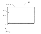
図4は、実施の形態に係る第一外装体11の概略構成を示す上面図である。
FIG. 4 is a top view illustrating a schematic configuration of the first
図4に示すように、第一外装体11は、平面視矩形状の底板111と、底板111の全周に亘って当該底板111の周縁から立設し、上方に向かって開放した第一開口112をなす第一周縁部113とを備えている。つまり、第一周縁部113は、第一外装体11の外周壁である。
As shown in FIG. 4, the first
第一周縁部113の上部付近の外側面には、外方に向けて突出する第一突起114及び第三突起115が水平方向に互いに交互に隙間なく並んで配置されている。具体的には、第一突起114及び第三突起115は、第一周縁部113の外側面の同一高さ位置に配置されている。第一突起114は、第一周縁部113の一対の長側面のそれぞれに対して2つずつ所定の間隔をあけて設けられている。第三突起115は、第一周縁部113の外側面であって、第一突起114が設けられていない領域に連続して設けられている。
On the outer surface in the vicinity of the upper portion of the first
次に、第二外装体12について説明する。
Next, the second
図1及び図2に示すように、第二外装体12は、第一外装体11の開口を閉塞する蓋体である。第二外装体12には、上面視略T字状に上方に突出した中空の収容突部80が形成されており、この収容突部80の内部空間に、回路基板(図示省略)やリレー(図示省略)などの電気機器と、これらに接続される配線(図示省略)とが収容されている。
As shown in FIGS. 1 and 2, the second
ここで、回路基板には、例えば、蓄電素子100の充電状態や放電状態、電圧値、電流値、温度などの各種情報を取得し、監視し、制御したり、リレーのオン、オフを制御したり、他の機器と通信を行ったりするための制御回路が設けられている。
Here, the circuit board acquires, monitors, and controls various information such as the charging state and discharging state of the
また、第二外装体12の内面側において、正極外部端子13とバスバー41とが接続され、負極外部端子14とバスバー42とが接続されている。バスバー41、42を介して、蓄電ユニット20は正極外部端子13、負極外部端子14に電気的に接続されている。
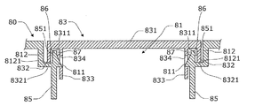
収容突部80の上面には、正極外部端子13に接続されるバスバー41と蓄電ユニット20のバスバー200との接続部分を露出させるための第一露出口81と、負極外部端子14に接続されるバスバー42と蓄電ユニット20のバスバー200との接続部分を露出させるための第二露出口82とが設けられている。第一露出口81及び第二露出口82は、上記接続部分の接続後に閉塞部材83、84によって閉塞されている。閉塞部材83、84は接着剤によって収容突部80と接合され、組み立て後においては、第一露出口81及び第二露出口82は密閉されている。
Further, on the inner surface side of the second
The upper surface of the
図5は、実施の形態に係る第一露出口81と、閉塞部材83との組み立て状態を示す断面図である。具体的には、図5は、図1におけるV−V線を含む切断面を見た断面図である。なお、第二露出口82と閉塞部材84との組み立て状態も、第一露出口81と閉塞部材83との係合状態と概ね同様であるので、その説明は省略する。
FIG. 5 is a cross-sectional view showing an assembled state of the
図5に示すように、収容突部80には、第一露出口81をなす周壁85が設けられている。周壁85の内周面においては、複数の係合爪811が周方向に所定の間隔をあけて形成されている。係合爪811は、第一露出口81の内方に向けて突出しており、その上面が下方に向かうにつれて内方に傾く傾斜面となっている。また、係合爪811の下面は水平面である。また、収容突部80には、周壁85の外方に、第一露出口81の周縁に沿う外周溝812が形成されている。
As shown in FIG. 5, the
閉塞部材83は、第一露出口81を閉塞する形状に形成された板部831と、板部831の全周に亘って当該板部831の周縁から垂下した壁部832と、板部831における壁部832よりも内方であって、係合爪811に対応する位置から下方に延在する突片833とを備える。
The closing
突片833には、係合爪811が係合する係合孔834が形成されている。係合孔834に係合爪811が係合した状態では、閉塞部材83が上方に浮き上がろうとした際に係合孔834の下面に対して係合爪811の下面が重なって当接する。これにより、閉塞部材83の上方への移動(浮き)が規制されている。
The
一方、壁部832の下面8321は、外周溝812の底面8121に当接している。この状態では周壁85の上端面851が、板部831の底面8311から離間して隙間86を形成している。この隙間86は、接着領域であり、周壁85の上端面851を板部831の底面8311に接着するための接着剤87が配置されている。
On the other hand, the
例えば、閉塞部材83を第一露出口81に取り付ける際には、先に、閉塞部材83の壁部832と突片833との間に接着剤87を塗布しておく。その後、閉塞部材83を第一露出口81に対して押し込める。このとき、突片833の下端部が係合爪811の上面をスライドして、突片833全体が内方に向けて曲げられながら、係合爪811を乗り越え、最終的に係合孔834に対して係合爪811が係合する。一方、周壁85の上端面851と、板部831の底面8311との間には接着剤87が塗布されているので、周壁85と板部831とを強固に接着することができる。
For example, when attaching the closing
図6は、実施の形態に係る第二外装体12の概略構成を示す下面図である。
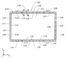
FIG. 6 is a bottom view showing a schematic configuration of the second
図6に示すように、第二外装体12は、平面視矩形状の天板121と、天板121の全周に亘って当該天板121の周縁から垂下し、下方に向かって開放した第二開口122をなす第二周縁部123とを備えている。つまり、第二周縁部123は、第二外装体12の外周壁である。また、天板121における第二周縁部123の内方には、天板121の全周に亘って形成された内周壁124が形成されている。第二周縁部123と内周壁124とは二重の壁体である。第二周縁部123と内周壁124との間の平面視環状の領域には、第一外装体11の第一周縁部113の上端部が収容され、当該上端部が接着される。このため、この第二周縁部123と内周壁124との間の平面視環状の領域を接着領域125とする。接着領域125は、第一外装体11と第二外装体12とを接着する際に、接着剤50(図7及び図8参照)が配置される領域である。つまり、内周壁124における接着領域125側の側面と、第二周縁部123における接着領域125側の側面とは、互いに対向している。
As shown in FIG. 6, the second
内周壁124における接着領域125側の側面には、第一外装体11の上端部を接着位置に案内する複数の案内部126が、周方向に所定の間隔をあけて配置されている。
On the side surface of the inner
第二周縁部123における接着領域125側の側面には、複数の第二突起127と、複数の第四突起128とが設けられている。複数の第二突起127のそれぞれは、第二外装体12が第一外装体11に取り付けられた際に、複数の第一突起114のそれぞれに対応するように、配置されている。複数の第四突起128は、第二外装体12が第一外装体11に取り付けられた際に、第一外装体11の第三突起115に対応するように、周方向に所定の間隔をあけて配置されている。
A plurality of
次に、第二外装体12が第一外装体11に取り付けられた際の第一突起114と第二突起127との係合状態について説明する。
Next, the engagement state between the
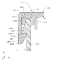
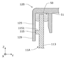
図7は、実施の形態に係る第一突起114と第二突起127との係合状態を示す断面図である。具体的には、図7は、図6におけるVII−VII線の位置に対応する断面図である。
FIG. 7 is a cross-sectional view showing an engaged state between the
図7に示すように、第一周縁部113の上部は、第二外装体12の接着領域125内に収容されている。そして、第一突起114の上面1141は、下方に向かうにつれて外方に傾斜する傾斜面となっている。第一突起114の上面1141と、第一周縁部113の上端面1131とは連続している。また、第一突起114の下面1142は、外方側が僅かに上方に傾いた概ね水平な面に形成されている。
As shown in FIG. 7, the upper part of the first
第二周縁部123は、第一突起114よりも下方に延びる延長部としてのスカート部129を備えている。このスカート部129における接着領域125側の側面(内側面)には、第一突起114の下面1142に対向するように、第二突起127が形成されている。第二突起127の上面1271は、水平面であり、第一突起114の下面1142と対向している。第二突起127の下面1272は、下方に向かうにつれて外方に傾斜する傾斜面である。
The second
このように、第二突起127の下面1272が、下方に向かうにつれて外方に傾斜する傾斜面であるので、第二外装体12を第一外装体11に取り付ける際には、第二外装体12の第二突起127の下面1272が第一突起114上をスライドする。これにより、第二外装体12の第二周縁部123が外方へと広がる。この広がりによって第二突起127が第一突起114を乗り越えるので、第一突起114の下方にスムーズに第二突起127を配置することができる。
Thus, since the
さらに、上述したように第一突起114の上面1141が、下方に向かうにつれて外方に傾斜する傾斜面であるので、第二外装体12を第一外装体11に取り付ける際には、第二突起の下面1272は、第一突起114の上面1141上をスライドする。このように第一突起114と第二突起127とが面接触でスライドすることにより、より容易に第一突起114の下方に第二突起127を配置することができる。
Furthermore, since the
なお、第一突起114の上面1141が傾斜面でなくとも、少なくとも第二突起127の下面1272が傾斜面であればよい。また、第二突起127の下面が水平面で、第一突起114の上面1141が傾斜面であってもよい。
Even if the
次に、第二外装体12が第一外装体11に取り付けられ際の第三突起115と第四突起128との当接状態について説明する。
Next, a contact state between the
図8は、実施の形態に係る第三突起115と第四突起128との当接状態を示す断面図である。具体的には、図8は、図6におけるVIII−VIII線の位置に対応する断面図である。
FIG. 8 is a cross-sectional view showing a contact state between the
図8に示すように、第一周縁部113の上部は、第二外装体12の接着領域125内に収容されている。そして、第三突起115は、第一周縁部113の上端面1131から下方に所定の間隔をあけて配置されている。第三突起115の上面1151及び下面1152は、水平面である。第三突起115の下面1152は、第一突起114の下面1142と面一である。
As shown in FIG. 8, the upper part of the first
第二周縁部123のスカート部129は、第三突起115の下方に延びている。また、第二周縁部123における接着領域125側の側面(内側面)には、第三突起115の上面1151に当接する第四突起128が形成されている。第四突起128は天板121から連続して下方に延在している。そして、第四突起128の下面1282は、水平面であり、第三突起115の上面1151に当接して重なっている。このように、第四突起128が第三突起115に当接しているので、第二外装体12の下方への移動が規制されることになる。
The
そして、第四突起128に第三突起115が当接した状態においては、第二外装体12の天板121の下面1211と、第一周縁部113の上端面1131との間には、接着剤50を収容する隙間51が形成されている。この隙間51は、接着領域125の全周に亘って設けられている(図7及び図8参照)。このような隙間51が形成されていると、接着剤50を接着領域125の全周にわたって保持することができる。また、第一周縁部113の上端面1131から接着剤50が垂れたとしても、第一突起114と第三突起115とがそれ以上の垂れを遮ることになる。さらに、第二周縁部123のスカート部129が第一突起114及び第三突起115よりも下方に位置しているために、第一突起114及び第三突起115に付着した接着剤50をスカート部129で隠すことができる。なお、接着剤50は、第一周縁部113の内側面から垂れることもあるが、第一周縁部113の内側面は、もともと外部に露出しないために、蓄電装置1の外観性を阻害することはない。
In a state where the
また、図8に示すように、案内部126における接着領域125側の側面には、下方に向かうにつれて内方に傾斜する傾斜面1261が形成されている。第二外装体12を第一外装体11に取り付ける際には、第一周縁部113の上部が傾斜面1261上をスライドして、接着領域125内に案内される。つまり、傾斜面1261は、第一周縁部113の上部を接着位置まで案内する案内面である。
Further, as shown in FIG. 8, an
次に、蓄電装置1の製造方法について説明する。 Next, a method for manufacturing the power storage device 1 will be described.
図9は、実施の形態に係る蓄電装置1の製造方法を示すフローチャートである。 FIG. 9 is a flowchart illustrating a method for manufacturing power storage device 1 according to the embodiment.
図9に示すように、収容工程では、作業者は、第一外装体11の第一開口112に対して蓄電ユニット20、保持部材30及びバスバー41、42等を収容する(S101)。これにより、第一外装体11内に蓄電素子100が収容される。また、作業者は、第二外装体12の内面側に対して、バスバー41、42、回路基板やリレーなどの電気機器と、これらと蓄電ユニット20内の蓄電素子100とを接続するための配線(図示省略)とを収容する。
As shown in FIG. 9, in the housing step, the worker houses the
次いで、塗布工程では、作業者は、第二外装体12の接着領域125及び閉塞部材83の壁部832と突片833との間に対して接着剤を塗布する(S102)。
Next, in the application process, the operator applies an adhesive to the
そして、接着工程では、作業者は、蓄電素子100が収容された第一外装体11に対して、第二外装体12を取り付けて、第一外装体11の第一周縁部113の上端面1131と、第二外装体12とを接着剤50によって接着する(S103)。取り付け時においては、第一外装体11の第一周縁部113が、案内部126の傾斜面1261上をスライドして、接着位置に案内されるので、第一周縁部113の上端面1131が接着剤50に触れることになる。
In the bonding step, the operator attaches the second
その後、第一露出口81及び第二露出口82にてバスバー41、42とバスバー200とを接合した後、第二外装体12に対して、第一露出口81及び第二露出口82を閉塞するように、閉塞部材83、84を取り付け接着することで、蓄電装置1の組み立てが完了する。
Thereafter, the bus bars 41, 42 and the
以上のように、本発明の実施の形態に係る蓄電装置1によれば、第一周縁部113における第二周縁部123と対向する外側面と、第二周縁部123における第一周縁部113に対向する内側面との少なくとも一方には、他方に向けて突出する突起(第一突起114、第二突起127、第三突起115)が形成されているので、接着剤50が第一周縁部113の上端面から溢れたとしても、突起から下方に垂れることを抑制することができる。
As described above, according to the power storage device 1 according to the embodiment of the present invention, the outer peripheral surface of the first
また、第二周縁部123が第一周縁部113よりも外方に配置されているので、突起より上の接着剤50を覆い隠すことができ、蓄電装置1自体の外観性を高めることができる。
Moreover, since the 2nd
また、第一外装体11の第一周縁部113の外側面には、第一突起114が形成されているので、接着剤50が第一周縁部113の上端面1131から溢れたとしても、第一突起114から下方に垂れることを抑制することができる。また、スカート部129が第一突起114よりも下方に伸びており、さらにスカート部129には第一突起114の下面に対向する第二突起127が形成されているので、第一突起114に付着した接着剤50をスカート部129で隠すことができる。したがって、蓄電装置1の外観からは接着剤50が露出しにくくなり、蓄電装置1自体の外観性を高めることができる。
In addition, since the
ここで、第二外装体12においては、内部に配線、回路基板、バスバー41、42などが搭載されているが、水が侵入してしまうと、これらが腐食や絶縁不良等の不具合を生じるおそれがある。しかしながら、第一突起114の下面1142に対向する第二突起127が設けられていると、第二外装体12が第一外装体11から浮こうとしても、第二突起127が第一突起114に当接し、浮きが抑制される。このため、接着後においては高い防水性を確保することができる。これにより、第二外装体12内の配線、基板、バスバー41、42などにおける水を起因とした不具合の発生を抑制することができる。
Here, in the second
また、第一外装体11の第一周縁部113の外側面には、第三突起115が形成されているので、接着剤50が第一周縁部113の上端面1131から溢れたとしても、第三突起115から下方に垂れることを抑制することができる。また、第二外装体12においては、第三突起115の上面1151に当接する第四突起128よりもスカート部129が下方に伸びているので、第三突起115がスカート部129により覆われる。これにより、第三突起115に付着した接着剤50をスカート部129で隠すことができる。したがって、蓄電装置1の外観からは接着剤50が露出しにくくなり、蓄電装置1自体の外観性を高めることができる。
In addition, since the
また、第四突起128が、第三突起115の上面1151に当接することにより第二外装体12の下方への移動を規制するので、第一外装体11に対する第二外装体12の位置を合わせることができ、スムーズに組み立てを行うことができる。
Further, since the
また、第四突起128によって下方への移動を規制された第二外装体12と、第一周縁部113の上端面1131との間には、接着剤50を収容する隙間51が積極的に形成されているので、この隙間51内で接着剤50を保持することができる。ここで、接着剤を塗布せずに第二外装体を第一外装体にかぶせた際に隙間が形成されない形態では、接着剤を塗布したとしても第二外装体と第一周縁部の上端面との間に残存する接着剤は僅かなものになる。このように、積極的に隙間51が形成されていると、当該隙間51によってより多くの接着剤50が保持されるので、第一外装体11と第二外装体12との接着強度を安定させることができる。
Further, a
また、第一突起114と第三突起115とが水平方向に並んで配置されているので、第一突起114と第三突起115とによって接着剤50の垂れを確実に抑制することができる。また、第一突起114と第三突起115とが水平方向に並んでいるので、第一外装体11が上下方向に大型化することを抑制できる。
Further, since the
また、第二外装体12の第二突起127の下面1272が、下方に向かうにつれて外方に傾斜する傾斜面であるので、第二外装体12を第一外装体11に取り付ける際には、第二外装体12の第二突起127の傾斜面が第一突起114上をスライドする。これにより、第二外装体12の第二周縁部123が外方へと広がる。この広がりによって第二突起127が第一突起114を乗り越えるので、第一突起114の下方にスムーズに第二突起127を配置することができる。
In addition, since the
また、第一突起114の上面1141が、下方に向かうにつれて外方に傾斜する傾斜面であるので、第二外装体12を第一外装体11に取り付ける際には、第二外装体12の第二突起127は、第一突起114に設けられた傾斜面上をスライドする。これにより容易に第一突起114の下方に第二突起127を配置することができる。
In addition, since the
また、案内部126が第一外装体11の第一周縁部113を接着位置に案内するので、第二外装体12を第一外装体11に取り付ける際に、第一外装体11の第一周縁部113をスムーズに接着位置まで案内することができる。
Moreover, since the
ここで、非水電解質蓄電素子は、水系電解質蓄電素子と比べて、蓄電装置に内蔵される内部部材が多くなるのが一般的である。つまり、上述したように、非水電解質蓄電素子を用いた場合、浸水の影響を受ける部材も多くなるが、蓄電装置1が防水性を高める構成を有しているために、上記の作用効果を好適に奏することができる。 Here, the nonaqueous electrolyte power storage element generally has more internal members built in the power storage device than the aqueous electrolyte power storage element. That is, as described above, when a non-aqueous electrolyte power storage element is used, the number of members affected by water immersion increases, but the power storage device 1 has a configuration that improves waterproofness, and thus the above-described effects are achieved. It can play suitably.
そして、第一外装体11と、第二外装体12とを接着剤50にて接合することは、接着時に内部に熱影響を及ぼすことがないために好ましい。
And it is preferable to join the 1st
以上、本発明の実施の形態に係る蓄電装置について説明したが、本発明は、上記実施の形態に限定されるものではない。つまり、今回開示された実施の形態は全ての点で例示であって制限的なものではないと考えられるべきである。本発明の範囲は上記した説明ではなくて特許請求の範囲によって示され、特許請求の範囲と均等の意味及び範囲内での全ての変更が含まれることが意図される。 The power storage device according to the embodiment of the present invention has been described above, but the present invention is not limited to the above embodiment. That is, the embodiment disclosed this time should be considered as illustrative in all points and not restrictive. The scope of the present invention is defined by the terms of the claims, rather than the description above, and is intended to include any modifications within the scope and meaning equivalent to the terms of the claims.
なお、以降では、変形例について具体的に説明するが、上記実施の形態と同一の部分においては同一の符号を付し、その説明を省略する場合がある。 In the following, modifications will be described in detail, but the same parts as those in the above embodiment are denoted by the same reference numerals, and the description thereof may be omitted.
例えば、上記実施の形態では、第一外装体11に対して第一突起114と第三突起115とが水平方向に交互に並んでいる場合を例示して説明した。しかし、第一突起114または第三突起115のみが、第一外装体11の全周に対して連続して設けられていてもよい。
For example, in the above embodiment, the case where the
[変形例1]
図10は、変形例1に係る第一外装体11Aの概略構成を示す上面図である。具体的には、図10は、図4に対応する図である。
[Modification 1]
FIG. 10 is a top view illustrating a schematic configuration of the first
図10に示すように、第一外装体11Aの第一周縁部113の外側面には、第一突起114または第三突起115が、全周に亘って連続して形成されている。このように、第一突起114または第三突起115が第一周縁部113の全周に亘って設けられているので、1つの突起(第一突起114または第三突起115)であっても、接着剤50の垂れを確実に抑制することができる。
As shown in FIG. 10, the
例えば、第一突起114が第一周縁部113の全周に亘って設けられて、第三突起115が設けられていない場合には、第二突起127が、第一突起114の全体或いは部分的に対向するように設けられていればよい。第二突起127が存在する箇所においては、第一突起114及び第二突起127は、図7に示す形態である。
For example, when the
また、第三突起115が第一周縁部113の全周に亘って設けられて、第一突起114が設けられていない場合には、第四突起128が、第三突起115の全体或いは部分的に対向するように設けられていればよい。第四突起128が存在する箇所においては、第三突起115及び第四突起128は、図8に示す形態である。
In addition, when the
[変形例2]
図11は変形例2に係る第三突起115と第二突起127との係合状態を示す断面図である。
[Modification 2]
FIG. 11 is a cross-sectional view illustrating an engagement state between the
図11に示すように、第三突起115に対向する位置に第二突起127を設けてもよい。具体的には、第二突起127の上面1271は、第三突起115の下面1152に重なって当接している。第二突起127は、第三突起115の全体に対して当接しても、部分的に当接していてもよい。さらに、第一外装体11Aの全周に亘って第三突起115が形成されている場合には、第二突起127と第四突起128とが、異なる位置で第三突起115に当接するように設けられていてもよい。また、第二周縁部123のスカート部129が第三突起115よりも下方に位置しているために、第三突起115に付着した接着剤50をスカート部129で隠すことができる。
As shown in FIG. 11, the
[変形例3]
図12は、変形例3に係る第三突起115の概略構成を示す断面図である。
[Modification 3]
FIG. 12 is a cross-sectional view illustrating a schematic configuration of the
図12に示すように、第一外装体11Aには、全周に亘って第三突起115が形成されているが、第二外装体12Bには、突起(第二突起127及び第四突起128)が設けられていない形態であってもよい。この場合においても、第三突起115の上面1151で、接着剤50の垂れを抑制することができる。また、第三突起115は、第二外装体12Bの第二周縁部123の内側面に当接していることが好ましい。これにより、第二周縁部123が、第三突起115から接着剤50があふれることを抑制することができる。また、第二周縁部123のスカート部129が第三突起115よりも下方に位置しているために、第三突起115に付着した接着剤50をスカート部129で隠すことができる。
As shown in FIG. 12, the first
なお、第三突起115に代わって、第一突起114が第一外装体11Aの全周に亘って形成されていてもよい。
In place of the
[変形例4]
図13は、変形例4に係る第二突起127の概略構成を示す断面図である。
[Modification 4]
FIG. 13 is a cross-sectional view illustrating a schematic configuration of the
図13に示すように、第二外装体12Aには、全周に亘って第二突起127が形成されているが、第一外装体11Bには、突起(第一突起114及び第三突起115)が設けられていない形態であってもよい。また、第二突起127は、第一外装体11Bの第一周縁部113の外側面に当接している。この場合においても、第二突起127の上面1271で、接着剤50の垂れを抑制することができる。
As shown in FIG. 13, the second
なお、上記実施の形態及び変形例が備える各構成要素を任意に組み合わせてもよい。 In addition, you may combine each component with which the said embodiment and modification are provided arbitrarily.
本発明は、蓄電素子と、外装体とを備える蓄電装置に適用できる。 The present invention can be applied to a power storage device including a power storage element and an exterior body.
1 蓄電装置
10 外装体
11、11A、11B 第一外装体
12、12A,12B 第二外装体
13 正極外部端子
14 負極外部端子
20 蓄電ユニット
30 保持部材
41、42、200 バスバー
50、87 接着剤
51、86 隙間
80 収容突部
81 第一露出口
82 第二露出口
83、84 閉塞部材
85 周壁
100 蓄電素子
110 容器
111 底板
112 第一開口
113 第一周縁部
114 第一突起(突起)
115 第三突起(突起)
120 正極端子
121 天板
122 第二開口
123 第二周縁部
124 内周壁
125 接着領域
126 案内部
127 第二突起(突起)
128 第四突起(突起)
129 スカート部
130 負極端子
300 スペーサ
310 第一スペーサ
320 第二スペーサ
330 第三スペーサ
400 挟持部材
500 拘束部材
600 バスバーフレーム
700 遮熱プレート
811 係合爪
812 外周溝
831 板部
832 壁部
833 突片
834 係合孔
851、1131 上端面
1141、1151、1271 上面
1142、1152、1211、1272、1282、8321 下面
1261 傾斜面
8121、8311 底面
DESCRIPTION OF SYMBOLS 1
115 Third protrusion (protrusion)
120
128 Fourth protrusion (protrusion)
129
Claims (11)
前記外装体は、第一外装体と、前記第一外装体の上方に配置された第二外装体とを備え、
前記第一外装体は、上方に向かって開放した第一開口をなす第一周縁部を有し、
前記第二外装体は、下方に向かって開放した第二開口をなし、前記第一周縁部に対して外方から対向する第二周縁部を有し、
前記第一周縁部の上端面と、前記第二外装体とが接着剤により接着されており、
前記第一周縁部における前記第二周縁部と対向する外側面と、前記第二周縁部における前記第一周縁部に対向する内側面との少なくとも一方には、他方に向けて突出する突起が形成されている
蓄電装置。 A power storage device comprising a power storage element and an exterior body,
The exterior body includes a first exterior body and a second exterior body disposed above the first exterior body,
The first exterior body has a first peripheral edge portion forming a first opening opened upward,
The second exterior body has a second opening that opens downward, and has a second peripheral edge that faces the first peripheral edge from the outside,
The upper end surface of the first peripheral edge and the second exterior body are bonded with an adhesive,
A protrusion projecting toward the other is formed on at least one of the outer side surface of the first peripheral edge portion that faces the second peripheral edge portion and the inner side surface of the second peripheral edge portion that faces the first peripheral edge portion. Power storage device.
前記第二周縁部は、前記第一突起よりも下方に延びるスカート部を含み、
前記スカート部の前記内側面には、前記第一突起の下面に対向する第二突起が前記突起として形成されている
請求項1に記載の蓄電装置。 A first protrusion that is the protrusion is formed on the outer surface of the first peripheral edge,
The second peripheral edge portion includes a skirt portion extending downward from the first protrusion,
The power storage device according to claim 1, wherein a second protrusion that faces the lower surface of the first protrusion is formed on the inner side surface of the skirt portion as the protrusion.
前記第二周縁部の前記内側面には、前記第三突起の上面に当接する第四突起が前記突起として形成されており、
前記第二周縁部は、前記第三突起よりも下方に延びるスカート部を含む
請求項1に記載の蓄電装置。 A third protrusion, which is the protrusion, is formed on the outer surface of the first peripheral edge,
On the inner side surface of the second peripheral edge portion, a fourth protrusion that is in contact with the upper surface of the third protrusion is formed as the protrusion.
The power storage device according to claim 1, wherein the second peripheral edge portion includes a skirt portion that extends downward from the third protrusion.
請求項3に記載の蓄電装置。 A gap for accommodating the adhesive between the second exterior body in a state in which the third protrusion is in contact with the fourth protrusion and the upper end surface of the first peripheral edge of the first exterior body. The power storage device according to claim 3.
前記第二周縁部の前記内側面には、前記第三突起の上面に当接する第四突起が配置されている
請求項2に記載の蓄電装置。 The first protrusion and a third protrusion that is the protrusion different from the first protrusion are arranged side by side in the horizontal direction on the outer side surface of the first peripheral edge.
The power storage device according to claim 2, wherein a fourth protrusion that abuts on an upper surface of the third protrusion is disposed on the inner side surface of the second peripheral edge.
請求項3または4に記載の蓄電装置。 The said 3rd protrusion and the 1st protrusion which is the said protrusion different from the said 3rd protrusion are arrange | positioned along with the horizontal direction in the said outer surface of a said 1st peripheral part. Power storage device.
請求項2または5に記載の蓄電装置。 The power storage device according to claim 2, wherein the lower surface of the second protrusion is an inclined surface that is inclined outward as it goes downward.
請求項2、5、6、7のいずれか一項に記載の蓄電装置。 The power storage device according to any one of claims 2, 5, 6, and 7, wherein an upper surface of the first protrusion is an inclined surface that is inclined outward as it goes downward.
請求項1〜8のいずれか一項に記載の蓄電装置。 The guide part which guides the 1st peripheral part of a said 1st exterior body to an adhesion | attachment position is provided inside the said 2nd peripheral part in said 2nd exterior body. The power storage device according to item.
請求項1〜9のいずれか一項に記載の蓄電装置。 The power storage device according to claim 1, wherein the power storage element is a non-aqueous electrolyte power storage element.
前記外装体は、第一外装体と、前記第一外装体の上方に配置された第二外装体とを備え、
前記第一外装体は、上方に向かって開放した第一開口をなす第一周縁部を有し、
前記第二外装体は、下方に向かって開放した第二開口をなし、前記第一周縁部に対して外方から対向する第二周縁部を有し、
前記第一周縁部における前記第二周縁部と対向する外側面と、前記第二周縁部における前記第一周縁部に対向する内側面との少なくとも一方には、他方に向けて突出する突起が形成されており、
前記製造方法は、
前記第一外装体の前記第一開口内に前記蓄電素子を収容する工程と、
前記第二外装体に対して接着剤を塗布する工程と、
前記蓄電素子が収容された前記第一外装体に対して、前記第二外装体を取り付けて、前記第一外装体の前記第一周縁部の上端面と、前記第二外装体とを前記接着剤によって接着する工程とを含む
蓄電装置の製造方法。 A method of manufacturing a power storage device including a power storage element and an exterior body,
The exterior body includes a first exterior body and a second exterior body disposed above the first exterior body,
The first exterior body has a first peripheral edge portion forming a first opening opened upward,
The second exterior body has a second opening that opens downward, and has a second peripheral edge that faces the first peripheral edge from the outside,
A protrusion projecting toward the other is formed on at least one of the outer side surface of the first peripheral edge portion that faces the second peripheral edge portion and the inner side surface of the second peripheral edge portion that faces the first peripheral edge portion. Has been
The manufacturing method includes:
Accommodating the electricity storage element in the first opening of the first exterior body;
Applying an adhesive to the second exterior body;
The second exterior body is attached to the first exterior body in which the power storage element is accommodated, and the upper end surface of the first peripheral portion of the first exterior body and the second exterior body are bonded together. The manufacturing method of an electrical storage apparatus including the process of adhere | attaching with an agent.
Priority Applications (1)
| Application Number | Priority Date | Filing Date | Title |
|---|---|---|---|
| JP2016032547A JP6780261B2 (en) | 2016-02-23 | 2016-02-23 | Power storage device |
Applications Claiming Priority (1)
| Application Number | Priority Date | Filing Date | Title |
|---|---|---|---|
| JP2016032547A JP6780261B2 (en) | 2016-02-23 | 2016-02-23 | Power storage device |
Publications (2)
| Publication Number | Publication Date |
|---|---|
| JP2017152165A true JP2017152165A (en) | 2017-08-31 |
| JP6780261B2 JP6780261B2 (en) | 2020-11-04 |
Family
ID=59742017
Family Applications (1)
| Application Number | Title | Priority Date | Filing Date |
|---|---|---|---|
| JP2016032547A Active JP6780261B2 (en) | 2016-02-23 | 2016-02-23 | Power storage device |
Country Status (1)
| Country | Link |
|---|---|
| JP (1) | JP6780261B2 (en) |
Cited By (4)
| Publication number | Priority date | Publication date | Assignee | Title |
|---|---|---|---|---|
| JP2021114422A (en) * | 2020-01-20 | 2021-08-05 | 株式会社Gsユアサ | Power storage device |
| JP2023072919A (en) * | 2021-11-15 | 2023-05-25 | プライムプラネットエナジー&ソリューションズ株式会社 | battery pack |
| FR3134924A1 (en) * | 2022-04-26 | 2023-10-27 | Psa Automobiles Sa | RIBBED BATTERY COVER |
| WO2024009929A1 (en) * | 2022-07-08 | 2024-01-11 | 株式会社Gsユアサ | Power storage device |
Citations (3)
| Publication number | Priority date | Publication date | Assignee | Title |
|---|---|---|---|---|
| JPH09251850A (en) * | 1996-03-14 | 1997-09-22 | Matsushita Electric Ind Co Ltd | Lead-acid battery |
| JP2003017019A (en) * | 2001-06-29 | 2003-01-17 | Sony Corp | Case |
| JP2011035856A (en) * | 2009-08-06 | 2011-02-17 | Panasonic Corp | Waterproof portable terminal apparatus |
-
2016
- 2016-02-23 JP JP2016032547A patent/JP6780261B2/en active Active
Patent Citations (3)
| Publication number | Priority date | Publication date | Assignee | Title |
|---|---|---|---|---|
| JPH09251850A (en) * | 1996-03-14 | 1997-09-22 | Matsushita Electric Ind Co Ltd | Lead-acid battery |
| JP2003017019A (en) * | 2001-06-29 | 2003-01-17 | Sony Corp | Case |
| JP2011035856A (en) * | 2009-08-06 | 2011-02-17 | Panasonic Corp | Waterproof portable terminal apparatus |
Cited By (7)
| Publication number | Priority date | Publication date | Assignee | Title |
|---|---|---|---|---|
| JP2021114422A (en) * | 2020-01-20 | 2021-08-05 | 株式会社Gsユアサ | Power storage device |
| JP7400488B2 (en) | 2020-01-20 | 2023-12-19 | 株式会社Gsユアサ | Power storage device |
| JP2023072919A (en) * | 2021-11-15 | 2023-05-25 | プライムプラネットエナジー&ソリューションズ株式会社 | battery pack |
| JP7502246B2 (en) | 2021-11-15 | 2024-06-18 | プライムプラネットエナジー&ソリューションズ株式会社 | Battery pack |
| FR3134924A1 (en) * | 2022-04-26 | 2023-10-27 | Psa Automobiles Sa | RIBBED BATTERY COVER |
| WO2023209298A1 (en) * | 2022-04-26 | 2023-11-02 | Psa Automobiles Sa | Ribbed battery cover |
| WO2024009929A1 (en) * | 2022-07-08 | 2024-01-11 | 株式会社Gsユアサ | Power storage device |
Also Published As
| Publication number | Publication date |
|---|---|
| JP6780261B2 (en) | 2020-11-04 |
Similar Documents
| Publication | Publication Date | Title |
|---|---|---|
| US10665837B2 (en) | Energy storage apparatus | |
| EP2955772B1 (en) | Battery pack | |
| US10333122B2 (en) | Energy storage apparatus | |
| US9153806B2 (en) | Power source unit | |
| US11069930B2 (en) | Energy storage apparatus | |
| WO2016199558A1 (en) | Power storage device | |
| US20130183544A1 (en) | Battery module and power source unit | |
| CN107104211B (en) | Power storage device and method for manufacturing power storage device | |
| US20200287194A1 (en) | Electrical connecting member housing case and battery module | |
| US10181620B2 (en) | Power source unit | |
| US10276840B2 (en) | Energy storage apparatus and method of manufacturing the same | |
| EP4080673A1 (en) | Battery module comprising removable fuse assembly, and battery pack comprising same | |
| US20170084885A1 (en) | Energy storage apparatus | |
| JP2017152161A (en) | Power storage device | |
| JP6780261B2 (en) | Power storage device | |
| JP6759534B2 (en) | Power storage device | |
| US10388916B2 (en) | Energy storage apparatus | |
| JP7214965B2 (en) | power storage device | |
| US11239526B2 (en) | Energy storage apparatus | |
| JP2017152163A (en) | Power storage device and method for manufacturing power storage device | |
| KR102054413B1 (en) | Battery Pack | |
| US11502361B2 (en) | Energy storage apparatus | |
| JP2017059502A (en) | Power storage device | |
| JPWO2018230523A1 (en) | Power storage device | |
| JP6772875B2 (en) | Power storage device |
Legal Events
| Date | Code | Title | Description |
|---|---|---|---|
| A621 | Written request for application examination |
Free format text: JAPANESE INTERMEDIATE CODE: A621 Effective date: 20181107 |
|
| A131 | Notification of reasons for refusal |
Free format text: JAPANESE INTERMEDIATE CODE: A131 Effective date: 20191001 |
|
| A977 | Report on retrieval |
Free format text: JAPANESE INTERMEDIATE CODE: A971007 Effective date: 20190930 |
|
| A521 | Request for written amendment filed |
Free format text: JAPANESE INTERMEDIATE CODE: A523 Effective date: 20191127 |
|
| A131 | Notification of reasons for refusal |
Free format text: JAPANESE INTERMEDIATE CODE: A131 Effective date: 20200303 |
|
| A521 | Request for written amendment filed |
Free format text: JAPANESE INTERMEDIATE CODE: A523 Effective date: 20200427 |
|
| TRDD | Decision of grant or rejection written | ||
| A01 | Written decision to grant a patent or to grant a registration (utility model) |
Free format text: JAPANESE INTERMEDIATE CODE: A01 Effective date: 20200915 |
|
| A61 | First payment of annual fees (during grant procedure) |
Free format text: JAPANESE INTERMEDIATE CODE: A61 Effective date: 20200928 |
|
| R150 | Certificate of patent or registration of utility model |
Ref document number: 6780261 Country of ref document: JP Free format text: JAPANESE INTERMEDIATE CODE: R150 |