JP2017148979A - Printer and printing method - Google Patents
Printer and printing method Download PDFInfo
- Publication number
- JP2017148979A JP2017148979A JP2016031688A JP2016031688A JP2017148979A JP 2017148979 A JP2017148979 A JP 2017148979A JP 2016031688 A JP2016031688 A JP 2016031688A JP 2016031688 A JP2016031688 A JP 2016031688A JP 2017148979 A JP2017148979 A JP 2017148979A
- Authority
- JP
- Japan
- Prior art keywords
- symbol image
- enlarged
- resolution
- printer
- printing
- Prior art date
- Legal status (The legal status is an assumption and is not a legal conclusion. Google has not performed a legal analysis and makes no representation as to the accuracy of the status listed.)
- Pending
Links
Images


Abstract
Description
本発明は、プリンター及び印刷方法に関し、特に、ユーザーがディスプレイ上で印刷範囲を指定しなくても、自動で見栄えの良い場所にシンボル画像(例えば、バーコード画像や2次元コード画像)を配置して印刷できるプリンター及び印刷方法に関する。 The present invention relates to a printer and a printing method, and in particular, a symbol image (for example, a barcode image or a two-dimensional code image) is automatically arranged in a place that looks good without a user specifying a printing range on a display. The present invention relates to a printer capable of printing and a printing method.
従来、ホストコンピューターから低解像度用のバーコード画像を印刷するためのコマンドを受信し、当該受信されたコマンドに基づき高解像度用のバーコード画像を生成し、その生成した高解像度用のバーコード画像をユーザーによって指定された印刷範囲に配置して印刷することが可能なプリンターが存在する(例えば、特許文献1参照)。 Conventionally, a command for printing a barcode image for low resolution is received from a host computer, a barcode image for high resolution is generated based on the received command, and the generated barcode image for high resolution is generated. There is a printer that can arrange and print in a printing range designated by the user (for example, see Patent Document 1).
しかしながら、上記のプリンターでは、印刷する前にユーザーがその高解像度用のバーコード画像をディスプレイに表示してディスプレイ上で印刷範囲を指定しなければならず、使い勝手がよくないという課題がある。 However, in the above-described printer, there is a problem that the user has to display the barcode image for high resolution on the display and designate a printing range on the display before printing, which is not convenient.
本発明は、上記事情に鑑みてなされたものであり、ユーザーがディスプレイ上で印刷範囲を指定しなくても、自動で見栄えの良い場所にシンボル画像(例えば、バーコード画像や2次元コード画像)を配置して印刷できるプリンター及び印刷方法を提供することを目的とする。 The present invention has been made in view of the above circumstances, and a symbol image (for example, a barcode image or a two-dimensional code image) is automatically displayed in a place where the appearance is good without the user specifying a print range on the display. It is an object of the present invention to provide a printer and a printing method that can arrange and print.
上記目的を達成するために、本発明の一つの側面は、外部装置に接続可能なプリンターであって、前記外部装置から、第1解像度用のシンボル画像を印刷するためのコマンドを含む印刷データを受信する受信部と、前記第1解像度より高い第2解像度の印刷ヘッドを備えた印刷機構と、前記受信部によって受信された印刷データに基づき、基本シンボル画像を生成する第1生成部と、前記第1生成部によって生成された前記基本シンボル画像を第2の整数倍拡大することで、前記第1生成部によって生成された前記基本シンボル画像を第1の整数倍拡大することで生成される前記第1解像度用の第1拡大シンボル画像より小サイズの、前記第2解像度用の第2拡大シンボル画像を生成する第2生成部と、前記第2生成部によって生成された前記第2拡大シンボル画像が、前記第1拡大シンボル画像の仮想輪郭内に印刷されるように前記印刷機構を制御する印刷制御部と、を備えたことを特徴とする。 In order to achieve the above object, one aspect of the present invention is a printer that can be connected to an external device, and print data including a command for printing a symbol image for the first resolution from the external device. A receiving unit for receiving, a printing mechanism including a print head having a second resolution higher than the first resolution, a first generating unit for generating a basic symbol image based on the print data received by the receiving unit, The basic symbol image generated by the first generation unit is enlarged by a second integer multiple, and the basic symbol image generated by the first generation unit is generated by a first integer multiple enlargement. A second generation unit that generates a second enlarged symbol image for the second resolution that is smaller in size than the first enlarged symbol image for the first resolution; Second magnification symbol image, characterized by comprising: a print controller for controlling the printing mechanism to be printed to a virtual contour in the first expansion symbol image.
この側面によれば、ユーザーがディスプレイ上で印刷範囲を指定しなくても、自動で見栄えの良い場所にシンボル画像(例えば、バーコード画像や2次元コード画像)を配置して印刷できるプリンターを提供できる。 According to this aspect, it is possible to provide a printer that can automatically place and print a symbol image (for example, a barcode image or a two-dimensional code image) in a place that looks good without the user specifying a print range on the display. it can.
これは、第2拡大シンボル画像が、第1拡大シンボル画像の仮想輪郭内に(例えば、当該仮想輪郭に対してセンタリングされた状態で)印刷されるように印刷機構を制御するようにしたことによるものである。 This is because the printing mechanism is controlled so that the second enlarged symbol image is printed within the virtual outline of the first enlarged symbol image (for example, centered with respect to the virtual outline). Is.
また、上記発明において、好ましい態様は、前記印刷制御部は、前記第2生成部によって生成された前記第2拡大シンボル画像が、前記第1拡大シンボル画像の仮想輪郭内に当該仮想輪郭に対してセンタリングされた状態で印刷されるように前記印刷機構を制御することを特徴とする。 In the above invention, a preferable aspect is that the print control unit is configured such that the second enlarged symbol image generated by the second generation unit is within the virtual outline of the first enlarged symbol image with respect to the virtual outline. The printing mechanism is controlled so that printing is performed in a centered state.
この態様によれば、ユーザーがディスプレイ上で印刷範囲を指定しなくても、自動で見栄えの良い場所にシンボル画像(例えば、バーコード画像や2次元コード画像)を配置して印刷できるプリンターを提供できる。 According to this aspect, it is possible to provide a printer that can automatically place and print a symbol image (for example, a barcode image or a two-dimensional code image) in a place that looks good without requiring the user to specify a print range on the display. it can.
これは、第2拡大シンボル画像が、前記第1拡大シンボル画像の仮想輪郭内に当該仮想輪郭に対してセンタリングされた状態で印刷されるように前記印刷機構を制御することによるものである。 This is because the printing mechanism is controlled so that the second enlarged symbol image is printed within the virtual outline of the first enlarged symbol image while being centered with respect to the virtual outline.
また、上記発明において、好ましい態様は、前記第2生成部によって生成された前記第2拡大シンボル画像は、横方向及び縦方向のうち少なくとも一方にセンタリングされることを特徴とする。 In the above invention, a preferred aspect is characterized in that the second enlarged symbol image generated by the second generation unit is centered in at least one of a horizontal direction and a vertical direction.
この態様によれば、第2拡大シンボル画像を、第1拡大シンボル画像の仮想輪郭内に当該仮想輪郭に対して、横方向(用紙幅方向)及び縦方向(用紙送り方向)のうち少なくとも一方にセンタリングした状態で印刷できる。 According to this aspect, the second enlarged symbol image is centered in at least one of the horizontal direction (paper width direction) and the vertical direction (paper feed direction) with respect to the virtual outline in the virtual outline of the first enlarged symbol image. Can be printed.
また、上記発明において、好ましい態様は、前記第2の整数倍は、前記第2拡大シンボル画像のサイズが前記第1拡大シンボル画像に最も近くなる整数倍であることを特徴とする。 In the above invention, a preferred aspect is characterized in that the second integer multiple is an integer multiple in which the size of the second enlarged symbol image is closest to the first enlarged symbol image.
この態様によれば、第2拡大シンボル画像の読み取り精度が低下するのを抑制し、なおかつ、第2拡大シンボル画像の見た目のサイズを第1拡大シンボル画像に近づけることができる。 According to this aspect, it is possible to suppress the reading accuracy of the second enlarged symbol image from being lowered, and to make the apparent size of the second enlarged symbol image closer to the first enlarged symbol image.
また、上記目的を達成するために、本発明の別の側面は、外部装置に接続可能なプリンターにおける印刷方法であって、前記外部装置から、第1解像度用のシンボル画像を印刷するためのコマンドを含む印刷データを受信する受信工程と、前記受信工程によって受信された印刷データに基づき、基本シンボル画像を生成する第1生成工程と、前記第1生成工程によって生成された前記基本シンボル画像を第1の整数倍拡大することで、前記第1生成工程によって生成された前記基本シンボル画像を第2の整数倍拡大することで生成される前記第1解像度の第1拡大シンボル画像より小サイズで、かつ、第2解像度の第2拡大シンボル画像を生成する第2生成工程と、前記第2生成工程によって生成された前記第2拡大シンボル画像が、前記第1拡大シンボル画像の仮想輪郭内に印刷されるように、前記第1解像度より高い第2解像度の印刷ヘッドを備えた印刷機構を制御する印刷制御工程と、を備えたことを特徴とする。 In order to achieve the above object, another aspect of the present invention provides a printing method in a printer connectable to an external device, the command for printing a symbol image for the first resolution from the external device. A receiving step for receiving print data including: a first generating step for generating a basic symbol image based on the print data received by the receiving step; and a first symbol generating the basic symbol image generated by the first generating step. The basic symbol image generated by the first generation step is enlarged by an integer multiple of 1, and smaller than the first enlarged symbol image of the first resolution generated by expanding the basic symbol image by a second integer multiple, And a second generation step of generating a second enlarged symbol image of the second resolution, and the second enlarged symbol image generated by the second generation step are As printed on the virtual contour of the enlarged symbol image, characterized in that and a print control step of controlling the printing mechanism with the higher than first resolution second resolution printing head.
この側面によれば、ユーザーがディスプレイ上で印刷範囲を指定しなくても、自動で見栄えの良い場所にシンボル画像(例えば、バーコード画像や2次元コード画像)を配置して印刷できる印刷方法を提供できる。 According to this aspect, there is provided a printing method in which a symbol image (for example, a barcode image or a two-dimensional code image) can be automatically arranged and printed in a place where the appearance is good without the user specifying a printing range on the display. Can be provided.
これは、基本シンボル画像を第2の整数倍(例えば、13倍)拡大することで、基本シンボル画像を第1の整数倍(例えば、4倍)拡大することで生成される第1解像度(例えば、180dpi)用の第1拡大シンボル画像より小サイズの、第2解像度(例えば、600dpi)用の第2拡大シンボル画像を生成し、当該生成された第2拡大シンボル画像が、第1拡大シンボル画像の仮想輪郭内に印刷されるように印刷機構を制御するようにしたことによるものである。 This is because the basic symbol image is enlarged by a second integer multiple (for example, 13 times), and the basic resolution is generated by enlarging the basic symbol image by a first integer multiple (for example, four times). , 180 dpi) a second enlarged symbol image for a second resolution (for example, 600 dpi) having a smaller size than the first enlarged symbol image for 180 dpi), and the generated second enlarged symbol image is the first enlarged symbol image. This is because the printing mechanism is controlled so as to be printed within the virtual contour.
以下、本発明の実施形態について添付図面を参照しながら説明する。各図において対応する構成要素には同一の符号が付され、重複する説明は省略される。 Hereinafter, embodiments of the present invention will be described with reference to the accompanying drawings. In each figure, corresponding components are denoted by the same reference numerals, and redundant description is omitted.
まず、本発明のプリンター及び印刷方法の実施形態の概要について説明する。 First, the outline | summary of embodiment of the printer of this invention and a printing method is demonstrated.
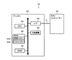
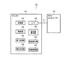
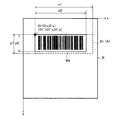
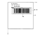
図1は本発明のプリンター及び印刷方法が適用されるPOSシステム10のシステム構成の一例を示す図、図2はプリンター40の機能構成の一例を示すブロック図である。図3は、基本シンボル画像SI0の一例である。図4は第1拡大シンボル画像SI1(の仮想輪郭A)と第2拡大シンボル画像SI2との関係を説明するための図、図5は第2拡大シンボル画像SI2がセンタリングされた様子を表す図である。
FIG. 1 is a diagram illustrating an example of a system configuration of a
本実施形態のプリンター40は、図1、図2に示すように、ホストコンピューター20(外部装置)に接続可能なプリンターであって、ホストコンピューター20から、第1解像度用(例えば、180dpi)のシンボル画像(例えば、バーコード画像や2次元コード画像)を印刷するためのコマンドを含む印刷データを受信する受信部52と、第1解像度より高い第2解像度(例えば、600dpi)の印刷ヘッドを備えた印刷機構50と、受信部52によって受信された印刷データに基づき、基本シンボル画像SI0(図3参照)を生成する第1生成部56と、第1生成部56によって生成された基本シンボル画像SI0を第2の整数N2(例えば、N2=13)倍拡大することで、第1生成部56によって生成された基本シンボル画像SI0を第1の整数N1(例えば、N1=4)倍拡大することで生成される第1解像度用の第1拡大シンボル画像SI1より小サイズの、第2解像度用の第2拡大シンボル画像SI2(図4参照)を生成する第2生成部58と、第2生成部58によって生成された第2拡大シンボル画像SI2が、第1拡大シンボル画像SI1の仮想輪郭A内に印刷される(図5参照)ように印刷機構50を制御する印刷制御部64と、を備える。
The
本実施形態のプリンター40によれば、ユーザーがディスプレイ上で印刷範囲を指定しなくても、自動で見栄えの良い場所にシンボル画像(例えば、バーコード画像や2次元コード画像)を配置して印刷できるプリンターを提供できる。
According to the
これは、第2拡大シンボル画像SI2が、第1拡大シンボル画像SI1の仮想輪郭A内に当該仮想輪郭Aに対してセンタリングされた状態で(つまり、仮想輪郭A内の中央位置に配置された状態で)印刷される(図5参照)ように印刷機構50を制御するようにしたことによるものである。
This is because the second enlarged symbol image SI 2 is centered with respect to the virtual outline A in the virtual outline A of the first enlarged symbol image SI 1 (that is, arranged at the center position in the virtual outline A). This is because the
以下、本発明のプリンター及び印刷方法が適用されるPOSシステム10について、図面を参照しながら詳細に説明する。
Hereinafter, the
図1に示すように、POSシステム10は、ホストコンピューター20、及び、プリンター40を備える。プリンター40は、第1解像度の印刷ヘッドを備えた旧プリンター(図示せず)から置き換えられたプリンターで、第1解像度より高い第2解像度の印刷ヘッドを備える。以下、第1解像度が180dpi、第2解像度が600dpiである場合を例に説明する。
As shown in FIG. 1, the
まず、ホストコンピューター20について説明する。
First, the
ホストコンピューター20(外部装置)は、図示しないが、ハード構成として、CPU、これにバスを介して接続された、RAM、ROM、HDD、各種I/F(インターフェース。以下同様)等を備える。 Although not shown, the host computer 20 (external device) includes a CPU, a RAM, a ROM, an HDD, various I / Fs (interfaces; the same applies hereinafter) and the like connected to the CPU via a bus.
ホストコンピューター20には、I/F(図示せず)を介してプリンター40が接続される。また、ホストコンピューター20には、図示しないが、I/Fを介して、バーコードを読み取るバーコードリーダー、キーボード等の入力装置、ディスプレイ等の表示装置が接続される。
A
ホストコンピューター20は、機能構成として、バーコードリーダーやキーボードからの入力に基づき、決済処理を行う機能、印刷データを生成する機能、プリンター40と通信ケーブルCを介して通信する機能、印刷データを通信ケーブルCを介してプリンター40へ送信する機能等を備える。これらの機能は、主に、ホストコンピューター20(CPU)が、ROM又はHDDからRAMに読み込まれた所定プログラム(オペレーティングシステム、POSアプリケーション、プリンタードライバー等)を実行することによって実現される公知の機能である。
The
本実施形態の印刷データは、レシートR(図5参照)を発行(印刷)するためのデータで、第1解像度(180dpi)用のシンボル画像を印刷するためのコマンドを含む。シンボル画像は、例えば、バーコード画像や2次元コード画像である。なお、印刷データは、決済情報(商品名、価格、合計金額等)を印刷するためのコマンドも含む。 The print data of this embodiment is data for issuing (printing) a receipt R (see FIG. 5), and includes a command for printing a symbol image for the first resolution (180 dpi). The symbol image is, for example, a barcode image or a two-dimensional code image. The print data includes a command for printing settlement information (product name, price, total amount, etc.).
第1解像度用のシンボル画像を印刷するためのコマンドは、例えば、基本シンボル画像SI0(図3参照)の基となるデータ、シンボル種類、第1の整数N1、基点O1を含む。これらは、例えば、ホストコンピューター20に接続された入力装置からユーザーによって入力される。
The command for printing the symbol image for the first resolution includes, for example, data that is the basis of the basic symbol image SI 0 (see FIG. 3), the symbol type, the first integer N1, and the base point O1. These are input by the user from an input device connected to the
第1解像度用のシンボル画像(以下、第1拡大シンボル画像SI1と称する。図4参照)は、基本シンボル画像SI0を第1の整数N1倍拡大することで生成され、基点O1を基準に印刷される。第1の整数N1及び基点O1は、置き換え前の旧プリンター(第1解像度(180dpi)の印刷ヘッド)で印刷した場合に、第1拡大シンボル画像SI1が所望の位置に所望のサイズで印刷されるようにユーザーによって指定される。 The symbol image for the first resolution (hereinafter referred to as the first enlarged symbol image SI 1 , see FIG. 4) is generated by enlarging the basic symbol image SI 0 by the first integer N1 and uses the base point O1 as a reference. Printed. First integer N1 and the base point O1, when printed in front of the old printer (first print head resolution (180 dpi)) replaces the first expansion symbol image SI 1 is printed in a desired size at a desired position Specified by the user.
基本シンボル画像SI0の基となるデータは、例えば、文字列である。 The data that is the basis of the basic symbol image SI 0 is, for example, a character string.
シンボル種類は、例えば、バーコード種類、2次元コード種類である。 The symbol type is, for example, a barcode type or a two-dimensional code type.
第1の整数N1は、基本シンボル画像SI0の拡大率で、整数で表される。 First integer N1 is the magnification of the basic symbol image SI 0, expressed as an integer.
基点O1は、第1拡大シンボル画像SI1を置き換え前の旧プリンター(第1解像度の印刷ヘッド)で印刷する場合の基準となる位置で、第1解像度の印刷ヘッドによって印刷される場合のx方向のドット位置O1x、及びy方向のドット位置O1yで表される(図4参照)。なお、用紙幅方向がx方向(横方向)、用紙送り方向がy方向(縦方向)である。 Base point O1 is a reference position when printing the old printer before replacing the first expansion symbol images SI 1 (first resolution printhead), x direction when printed by the first printhead resolution Dot position O1x and y-direction dot position O1y (see FIG. 4). The paper width direction is the x direction (horizontal direction), and the paper feed direction is the y direction (vertical direction).
次に、プリンター40について説明する。
Next, the
プリンター40は、典型的には、レシートプリンター(例えば、ドットインパクト、サーマル又はインクジェット方式)で、図1に示すように、ハード構成として、CPU42、これにバスを介して接続された、RAM44、ROM46、I/F48、印刷機構50等を備える。
The
RAM44は、受信バッファー44a、プリントバッファー44bを含む。
The
ROM46は、例えば、フラッシュROM等の不揮発性メモリーである。ROM46には、ファームウエア(制御プログラム)等の各種プログラム等が記憶される。
The
I/F48は、プリンター40をホストコンピューター20に接続するために設けられたインターフェースである。プリンター40(I/F48)とホストコンピューター20とは、通信ケーブルCによって接続される。
The I /
印刷機構50は、図示しないが、第1解像度(180dpi)より高い第2解像度(600dpi)の印刷ヘッド、用紙送り機構、用紙切断機構等を備える。
Although not shown, the
図2に示すように、プリンター40は、機能構成として、受信部52、解析部54、第1生成部56、第2生成部58、拡大率算出部60、基点算出部62、印刷制御部64等を備える。
As illustrated in FIG. 2, the
上記各機能は、主に、プリンター40(CPU42)が、ROM46からRAM44に読み込まれたファームウェア等の所定プログラムを実行することによって実現される。
The above functions are mainly realized by the printer 40 (CPU 42) executing a predetermined program such as firmware read from the
受信部52は、ホストコンピューター20からI/F48を介して印刷データを受信し、当該受信した印刷データを受信バッファー44aに記憶する。
The receiving
解析部54は、受信バッファー44aに記憶された印刷データを解析する。
The
第1生成部56は、受信部52によって受信された印刷データ(基本シンボル画像SI0の基となるデータ等)に基づきエンコードして、図3に示すように、基本シンボル画像SI0(例えば、100dot×50dot)を生成する。
The
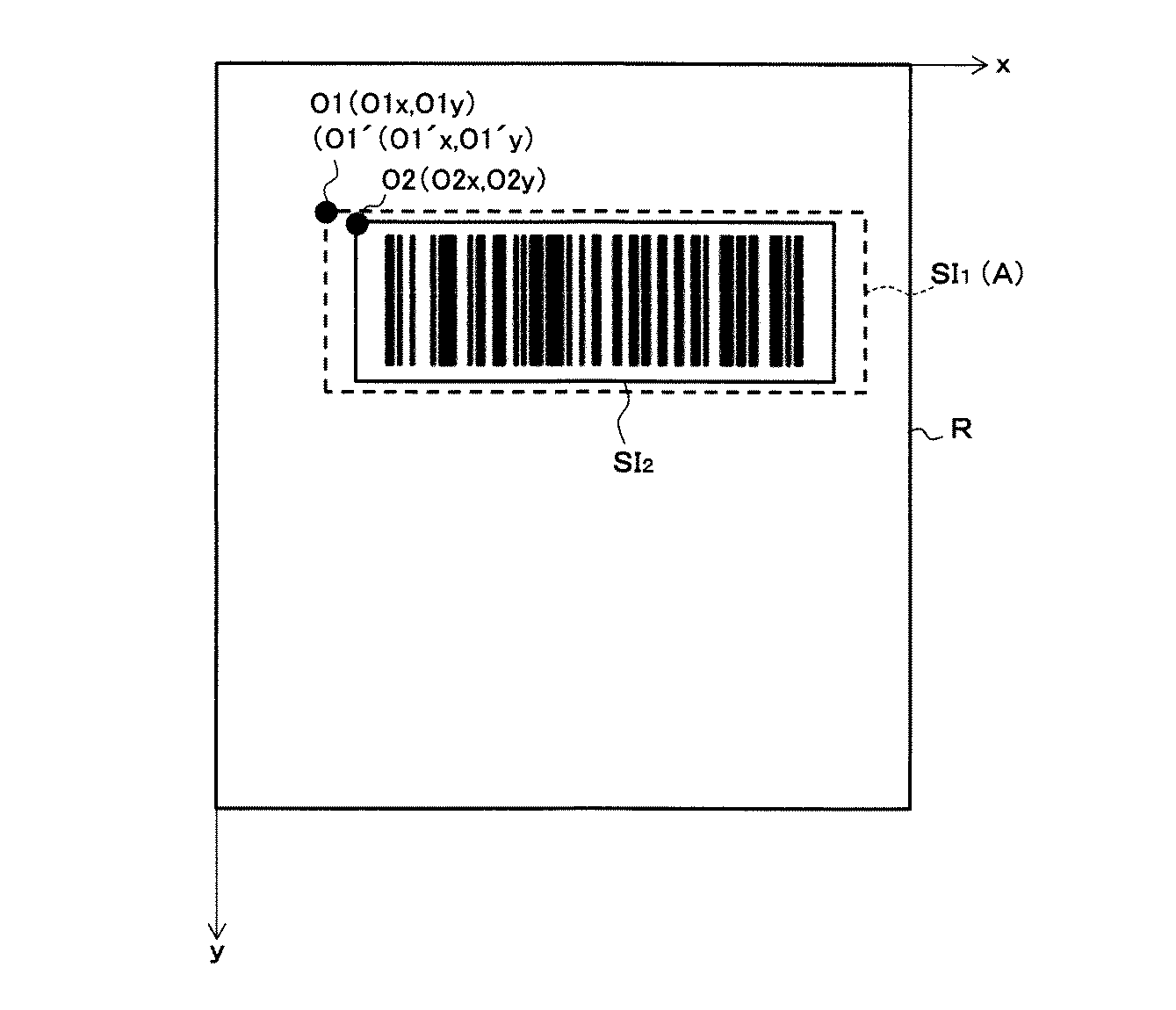
第2生成部58は、第1生成部56によって生成された基本シンボル画像SI0(図3参照)を第2の整数N2(後述の拡大率算出部60によって算出される第2の整数N2。例えば、N2=13)倍拡大することで、図4に示すように、第1生成部56によって生成された基本シンボル画像SI0を第1の整数N1(例えば、N1=4)倍拡大することで生成される第1解像度(180dpi)用の第1拡大シンボル画像SI1(第1解像度の印刷ヘッドによって印刷される第1拡大シンボル画像SI1)より小サイズの、第2解像度(600dpi)用の第2拡大シンボル画像SI2(第2解像度の印刷ヘッドによって印刷される第2拡大シンボル画像SI2)を生成する。なお、図4、図5中、第1拡大シンボル画像SI1は、その輪郭のみ示されている。
The
拡大率算出部60は、第2拡大シンボル画像SI2のサイズが第1拡大シンボル画像SI1(第1解像度の印刷ヘッドによって印刷される第1拡大シンボル画像SI1)に最も近くなる第2の整数N2を算出する。その理由は次のとおりである。
Enlargement
すなわち、基本シンボル画像SI0(例えば、100dot×50dot)を第1の整数N1(例えば、N1=4)倍拡大して置き換え前の旧プリンター(第1解像度の印刷ヘッド)で印刷した第1拡大シンボル画像SI1の大きさは、基本シンボル画像SI0(例えば、100dot×50dot)を13.333…倍拡大して置き換え後のプリンター40(第2解像度の印刷ヘッド)で印刷した拡大シンボル画像の大きさに等しい。これは、第1解像度(180dpi)の印刷ヘッドと第2解像度(600dpi)の印刷ヘッドとでは1ドットの大きさが異なるためである。 That is, the first enlargement obtained by enlarging the basic symbol image SI 0 (for example, 100 dots × 50 dots) by the first integer N1 (for example, N1 = 4) and printing it with the old printer (first resolution print head) before replacement. The size of the symbol image SI 1 is the same as that of the enlarged symbol image printed by the printer 40 (second resolution print head) after the basic symbol image SI 0 (for example, 100 dots × 50 dots) is magnified by 13.333. Equal to size. This is because the size of one dot is different between the print head of the first resolution (180 dpi) and the print head of the second resolution (600 dpi).
しかしながら、基本シンボル画像SI0を小数点以下を含む数値(上記例では13.333…)倍拡大すると、各バーの太さ(バーコード画像の場合)の比が拡大前と比べて場所ごとに変わってしまい、当該拡大シンボル画像の読み取り精度が低下してしまう。 However, when the basic symbol image SI 0 is enlarged by a numerical value including the decimal point (13.333 in the above example), the ratio of the thicknesses of the bars (in the case of barcode images) changes from place to place before the enlargement. As a result, the reading accuracy of the enlarged symbol image decreases.
そこで、読み取り精度が低下するのを抑制し、なおかつ、見た目のサイズを第1拡大シンボル画像SI1(第1解像度の印刷ヘッドによって印刷される第1拡大シンボル画像SI1)に近づける観点から、拡大率算出部60は、小数点以下を含む数値(上記例では13.333…)ではなく、小数点以下を切り捨て、第2拡大シンボル画像SI2のサイズが第1拡大シンボル画像SI1(第1解像度の印刷ヘッドによって印刷される第1拡大シンボル画像)に最も近くなる第2の整数N2(上記例では、N2=13)を算出する。以上のように、第2の整数N倍は、第2拡大シンボル画像SI2のサイズが第1拡大シンボル画像SI1(第1解像度の印刷ヘッドによって印刷される第1拡大シンボル画像SI1)に最も近くなる整数倍である。
Therefore, to suppress deterioration is reading accuracy, yet, from the viewpoint to approach the apparent size in the first expansion symbol images SI 1 (first enlarged symbol image SI 1 to be printed by the first printhead resolution), expanded The
基点算出部62は、図5に示すように、第2拡大シンボル画像SI2が、第1解像度の印刷ヘッドによって基点O1を基準に印刷される第1拡大シンボル画像SI1の仮想輪郭A内に当該仮想輪郭Aに対してセンタリングされた状態で印刷されるような基点O2を算出する。その理由は次のとおりである。
As illustrated in FIG. 5, the base
すなわち、第2拡大シンボル画像SI2は、基本シンボル画像SI0を小数点以下を含む数値(上記例では13.333…)倍ではなく、第2の整数N2(例えば、N2=13)倍拡大することで生成され、かつ、第2解像度の印刷ヘッドによって印刷されるものであるため、第1解像度の印刷ヘッドによって印刷される第1拡大シンボル画像SI1(の仮想輪郭A)より小サイズとなる(図4参照)。 That is, the second expansion symbol image SI 2 (in the above example 13.333 ...) numbers including decimal places basic symbol image SI 0 rather than the doubled second integer N2 (e.g., N2 = 13) to times magnified Therefore, the size is smaller than the first enlarged symbol image SI 1 (its virtual outline A) printed by the print head having the first resolution. (See FIG. 4).
そのため、第2拡大シンボル画像SI2を後述の基点O1´を基準に印刷すると(プリントバッファー44bに展開すると)、第1解像度の印刷ヘッドによって基点O1を基準に印刷される(プリントバッファーに展開される)第1拡大シンボル画像SI1と比べ、偏って(例えば、図4中、左側に偏って)印刷されてしまい(プリントバッファー44bに展開されてしまい)、見栄えが悪くなってしまう。
Therefore, when the second enlarged symbol image SI 2 prints the base point O1' described later (when expanded to the
そこで、見栄えを改善する観点から、基点算出部62は、図5に示すように、第2拡大シンボル画像SI2が、第1解像度の印刷ヘッドによって基点O1を基準に印刷される第1拡大シンボル画像SI1の仮想輪郭A内に当該仮想輪郭Aに対してセンタリングされた状態で(つまり、仮想輪郭A内の中央位置に配置された状態で)印刷されるような基点O2(O2x、O2y)を算出する。基点O2は、第2拡大シンボル画像SI2を置き換え後のプリンター40(第2解像度の印刷ヘッド)で印刷する場合の基準となる位置で、第2解像度の印刷ヘッドによって印刷される場合のx方向のドット位置O2x、及びy方向のドット位置O2yで表される(図5参照)。
Therefore, from the viewpoint of improving the appearance, the base
基点O2(O2x、O2y)は、例えば、次の式1、式2で算出できる。 The base point O2 (O2x, O2y) can be calculated by the following formulas 1 and 2, for example.
但し、x1、y1(図4参照)はそれぞれ、置き換え前の旧プリンター(第1解像度の印刷ヘッド)によって印刷される第1拡大シンボル画像SI1のx方向寸法(ドット数)、y方向寸法(ドット数)である。一方、x2、y2はそれぞれ、置き換え後のプリンター40(第2解像度の印刷ヘッド)によって印刷される第2拡大シンボル画像SI2のx方向寸法(ドット数)、y方向寸法(ドット数)である。
However, x1, y1 (see FIG. 4), respectively, the old printer x dimension (number of dots) of the first expansion symbol image SI 1 to be printed by the (first resolution printhead) before replacement, y dimension ( Dot number). On the other hand, x2, y2, respectively, the
基点O1´(O1´x、O1´y)は、置き換え後のプリンター40(第2解像度の印刷ヘッド)におけるx方向のドット位置、及びy方向のドット位置で、置き換え前の旧プリンター(第1解像度の印刷ヘッド)における基点O1(O1x、O1y)と見た目が同じ位置となるように、基点O1(O1x、O1y)を変換することで算出される。 The base point O1 ′ (O1′x, O1′y) is the dot position in the x direction and the dot position in the y direction in the replaced printer 40 (second resolution print head). It is calculated by converting the base point O1 (O1x, O1y) so that the appearance of the base point O1 (O1x, O1y) in the resolution print head) is the same position.
印刷制御部64は、第2生成部58によって生成された第2拡大シンボル画像SI2を、基点算出部62によって算出された基点O2(O2x、O2y)を基準にRAM44(プリントバッファー44b)に展開(描画)する。これにより、第2生成部58によって生成された第2拡大シンボル画像SI2は、第1拡大シンボル画像SI1の仮想輪郭A内に当該仮想輪郭Aに対してセンタリングされた状態でRAM44(プリントバッファー44b)に展開(描画)される。
The
また、印刷制御部64は、プリントバッファー44bに展開された第2拡大シンボル画像SI2に基づき、第2生成部58によって生成された第2拡大シンボル画像SI2が、第1拡大シンボル画像SI1の仮想輪郭A内に当該仮想輪郭Aに対して印刷されるように印刷機構50を制御する。また、印刷制御部64は、受信部52によって受信された印刷データに基づき印刷機構50を制御して、決済情報も印刷する。
The
次に、本実施形態のプリンター40の動作(印刷方法)の一例について図6を参照しながら説明する。
Next, an example of the operation (printing method) of the
図6は、本実施形態のプリンター40の動作(印刷方法)の一例を説明するためのフローチャートである。
FIG. 6 is a flowchart for explaining an example of the operation (printing method) of the
以下の処理は、主に、プリンター40(CPU42)が、ROM46からRAM44に読み込まれたファームウェア等の所定プログラムを実行することによって実現される。
The following processing is mainly realized by the printer 40 (CPU 42) executing a predetermined program such as firmware read from the
以下、第1解像度=180dpi、第2解像度=600dpi、第1の整数N1=4、基本シンボル画像SI0が100dot×50dotの場合を例に説明する。 Hereinafter, a case where the first resolution = 180 dpi, the second resolution = 600 dpi, the first integer N1 = 4, and the basic symbol image SI 0 is 100 dots × 50 dots will be described as an example.
プリンター40(受信部52)は、ホストコンピューター20から送信される印刷データをI/F48を介して受信し、当該受信した印刷データを受信バッファー44aに記憶する。これは、本発明の受信工程に相当する。受信バッファー44aに記憶された印刷データは、解析部54によって解析される。
The printer 40 (reception unit 52) receives print data transmitted from the
プリンター40(拡大率算出部60)は、受信部52によって印刷データが受信された場合(ステップS10:Yes)、第2拡大シンボル画像SI2のサイズが第1拡大シンボル画像SI1(第1解像度の印刷ヘッドによって印刷される第1拡大シンボル画像SI1)に最も近くなる第2の整数N2を算出する(ステップS12)。ここでは、第1解像度=180dpi、第2解像度=600dpi、第1の整数N1=4、基本シンボル画像SI0が100dot×50dotであるため、拡大率算出部60は、第2の整数N2=13を算出する。
Printer 40 (enlargement ratio calculation unit 60), when the print data by the receiving
次に、プリンター40(基点算出部62)は、図5に示すように、第2拡大シンボル画像SI2が、第1解像度の印刷ヘッドによって基点O1を基準に印刷される第1拡大シンボル画像SI1の仮想輪郭A内に当該仮想輪郭Aに対してセンタリングされた状態で印刷されるような基点O2(O2x、O2y)を算出する(ステップS14)。具体的には、基点算出部62は、上記式1、式2に基づき、基点O2(O2x、O2y)を算出する。
Next, the printer 40 (base calculator 62), as shown in FIG. 5, a second expansion symbol image SI 2 is first expanded symbol image SI that is printed on the base point O1 by a first resolution of the print head A base point O2 (O2x, O2y) that is printed in a state centered with respect to the virtual contour A within one virtual contour A is calculated (step S14). Specifically, the base
次に、プリンター40(第1生成部56)は、受信部52によって受信された印刷データ(基本シンボル画像SI0の基となるデータ等)に基づきエンコードして、図3に示すように、基本シンボル画像SI0(ここでは、100dot×50dot)を生成する(ステップS16)。これは、本発明の第1生成工程に相当する。
Next, the printer 40 (first generating unit 56) is encoded on the basis of the print data received (such as data on which to base the basic symbol image SI 0) by the receiving
次に、プリンター40(第2生成部58)は、第1生成部56によって生成された基本シンボル画像SI0を第2の整数N2(拡大率算出部60によって算出された第2の整数N2。ここでは、N2=13)倍拡大することで、図4に示すように、第1生成部56によって生成された基本シンボル画像SI0を第1の整数N1(ここでは、N1=4)倍拡大することで生成される第1解像度(180dpi)用の第1拡大シンボル画像SI1(第1解像度の印刷ヘッドによって印刷される第1拡大シンボル画像SI1)より小サイズの、第2解像度(600dpi)用の第2拡大シンボル画像SI2を生成する(ステップS18)。これは、本発明の第2生成工程に相当する。
Next, the printer 40 (second generating unit 58), a second integer N2 calculated the basic symbol image SI 0 generated by the
次に、プリンター40(印刷制御部64)は、第2生成部58によって生成された第2拡大シンボル画像SI2を、基点算出部62によって算出された基点O2(O2x、O2y)を基準にRAM44(プリントバッファー44b)に展開(描画)する。これにより、第2生成部58によって生成された第2拡大シンボル画像SI2は、第1拡大シンボル画像SI1の仮想輪郭A内に当該仮想輪郭Aに対してセンタリングされた状態でRAM44(プリントバッファー44b)に展開(描画)される。
Next, the printer 40 (printing control unit 64), a second expansion symbol image SI 2 generated by the
そして、印刷制御部64は、プリントバッファー44bに展開された第2拡大シンボル画像SI2に基づき、第2生成部58によって生成された第2拡大シンボル画像SI2が、図5に示すように、第1拡大シンボル画像SI1の仮想輪郭A内に当該仮想輪郭Aに対してセンタリングされた状態で(つまり、仮想輪郭A内の中央位置に配置された状態で)レシートRに印刷されるように印刷機構50を制御する(ステップS20)。これは、本発明の印刷制御工程に相当する。これにより、第2拡大シンボル画像SI2の読み取り精度が低下するのを抑制し、なおかつ、第2拡大シンボル画像SI2の見た目のサイズを第1拡大シンボル画像SI1(第1解像度の印刷ヘッドによって印刷される第1拡大シンボル画像SI1)に近づけることができる。なお、印刷制御部64は、図示しないが、受信部52によって受信された印刷データに基づき印刷機構50を制御して、決済情報もレシートRに印刷する。
Then, the
以上説明したとおり、本実施形態によれば、ユーザーがディスプレイ上で印刷範囲を指定しなくても、自動で見栄えの良い場所にシンボル画像(例えば、バーコード画像や2次元コード画像)を配置して印刷できるプリンター40を提供できる。
As described above, according to the present embodiment, a symbol image (for example, a barcode image or a two-dimensional code image) is automatically placed in a place that looks good even if the user does not specify a print range on the display. The
これは、第2拡大シンボル画像SI2が、第1拡大シンボル画像SI1の仮想輪郭A内に当該仮想輪郭Aに対してセンタリングされた状態で(つまり、仮想輪郭A内の中央位置に配置された状態で)印刷されるように印刷機構50を制御するようにしたことによるものである。
This is because the second enlarged symbol image SI 2 is centered with respect to the virtual outline A in the virtual outline A of the first enlarged symbol image SI 1 (that is, arranged at the center position in the virtual outline A). This is because the
また、本実施形態によれば、第2拡大シンボル画像SI2(第2解像度の印刷ヘッドによって印刷される第2拡大シンボル画像SI2)のサイズが第1拡大シンボル画像SI1(第1解像度の印刷ヘッドによって印刷される第1拡大シンボル画像SI1)より小さくなることに起因する、第2拡大シンボル画像SI2の印刷位置(プリントバッファー44bへの展開位置)の偏り(図4中左方向への偏り)を自動的に補正して、当該第2拡大シンボル画像SI2を、第1拡大シンボル画像SI1の仮想輪郭A内に当該仮想輪郭Aに対してセンタリングされた状態で(つまり、仮想輪郭A内の中央位置に配置された状態で)レシートRに印刷(プリントバッファー44bへ展開)できる(図5参照)。
Further, according to this embodiment, the size of the (second expansion symbol image SI 2 to be printed by the second printhead resolution) second expansion symbol image SI 2 is first expanded symbol images SI 1 (the first resolution Deviation (leftward direction in FIG. 4) of the printing position of the second enlarged symbol image SI 2 (the developed position on the
また、本実施形態によれば、第2拡大シンボル画像SI2の読み取り精度が低下するのを抑制し、なおかつ、第2拡大シンボル画像SI2の見た目のサイズを第1拡大シンボル画像SI1(第1解像度の印刷ヘッドによって印刷される第1拡大シンボル画像SI1)に近づけることができる。 Further, according to the present embodiment, it is possible to suppress the reading accuracy of the second enlarged symbol image SI 2 from being lowered, and to reduce the apparent size of the second enlarged symbol image SI 2 to the first enlarged symbol image SI 1 (first The first enlarged symbol image SI 1 ) printed by the 1-resolution print head can be approximated.
なお、本実施形態では、第2拡大シンボル画像SI2が、第1拡大シンボル画像SI1の仮想輪郭A内に当該仮想輪郭Aに対してセンタリングされた状態で印刷されるように説明したが、当該センタリングは、完全なセンタリングでなくてもよい。例えば、本来のセンタリング(つまり、仮想輪郭A内の中央位置)からx方向及びy方向のうち少なくとも一方の方向に関し、数ドット(例えば、1ドット)偏っていてもよい。 In the present embodiment, the second enlarged symbol image SI 2 has been described as being printed in a state centered with respect to the virtual outline A within the virtual outline A of the first enlarged symbol image SI 1 . The centering may not be complete centering. For example, the original centering (that is, the center position in the virtual contour A) may be deviated by several dots (for example, one dot) in at least one of the x direction and the y direction.
また、本実施形態では、第2拡大シンボル画像SI2を、x方向及びy方向に関しセンタリングするように説明したが、これに限らない。例えば、x方向に関してのみセンタリングしてもよいし、y方向に関してのみセンタリングしてもよい。このように、第2拡大シンボル画像SI2は、第1拡大シンボル画像SI1の仮想輪郭A内に当該仮想輪郭Aに対して、x方向(横方向)及びy方向(縦方向)のうち少なくとも一方にセンタリングした状態で印刷することもできる。 Further, in the present embodiment, the second expansion symbol image SI 2, have been described as being centered relates x and y directions, is not limited thereto. For example, centering may be performed only in the x direction, or centering may be performed only in the y direction. Thus, the second expansion symbol image SI 2 is with respect to the virtual contour A in the first expansion symbol image SI 1 in the virtual contour A, at least one of the x-direction (horizontal direction) and the y-direction (vertical direction) It is also possible to print with one centered.
また、本実施形態では、第2生成部58は、基本シンボル画像SI0をx方向及びy方向に関し第2の整数N2(例えば、N2=13)倍拡大することで、第2解像度(600dpi)用の第2拡大シンボル画像SI2を生成するように説明したが、これに限らない。
Further, in the present embodiment,
例えば、印刷データに含まれるシンボル種類をプリンター40において判別し、シンボル種別に応じて基本シンボル画像SI0を拡大する方向を異ならせてもよい。
For example, a symbol type included in the print data to determine in the
例えば、シンボル種類が2次元コードである場合、基本シンボル画像SI0をx方向及びy方向に関して第2の整数N2(例えば、N2=13)倍拡大することで、第2解像度(600dpi)用の第2拡大シンボル画像SI2を生成し、一方、シンボル種類がバーコードである場合、基本シンボル画像SI0をx方向に関してのみ第2の整数N2(例えば、N2=13)倍拡大することで、第2解像度(600dpi)用の第2拡大シンボル画像SI2を生成してもよい。 For example, if the symbol type is a two-dimensional code, the basic symbol image SI 0 the second integer in x and y directions N2 (e.g., N2 = 13) by fold expansion for the second resolution (600 dpi) When the second enlarged symbol image SI 2 is generated, while the symbol type is barcode, the basic symbol image SI 0 is enlarged by a second integer N2 (eg, N2 = 13) times only in the x direction, second resolution may generate the second expansion symbol image SI 2 for (600 dpi).
このようにすれば、シンボル種類がバーコードである場合、基本シンボル画像SI0をy方向に関して拡大しなくても読み取り精度にほとんど影響しないため、基本シンボル画像SI0をx方向に関してのみ拡大すればよく、そのため、第2拡大シンボル画像SI2の印刷領域(Y方向に関する印刷領域)を低減できる(つまり、用紙を節約できる)。 Thus, if the symbol type is a bar code, since hardly affect the basic symbol image SI 0 to be read accuracy without expanding the y-direction, by extension the basic symbol image SI 0 only for x-direction For this reason, the print area (print area in the Y direction) of the second enlarged symbol image SI 2 can be reduced (that is, paper can be saved).
また、シンボル種類が2次元コードである場合、基本シンボル画像SI0がx方向及びy方向に関して拡大されるため、一方向に関してのみ拡大する場合と比べ、読み取り精度が低下するのを抑制できる。 Also, if the symbol type is a two-dimensional code, for basic symbol image SI 0 is enlarged with respect to the x and y directions, compared with the case of expanding only for one direction, can prevent the reading accuracy is decreased.
なお、本実施形態では、プリンター40としてレシートプリンターを例示したが、これに限らず、レシートプリンター以外のプリンター(例えば、ラベルプリンター)にも、本発明を適用可能である。
In the present embodiment, a receipt printer is exemplified as the
また、上記実施形態では、第1解像度が180dpi、第2解像度が600dpiである場合を例に説明したが、これに限らず、第1解像度、第2解像度は、他の解像度であってもよい。 In the above embodiment, the case where the first resolution is 180 dpi and the second resolution is 600 dpi is described as an example. However, the present invention is not limited to this, and the first resolution and the second resolution may be other resolutions. .
また、上記実施形態では、基本シンボル画像SI0が100dot×50dotである場合を例に説明したが、これに限らず、基本シンボル画像SI0は、他のサイズであってもよい。 In the above embodiment, the case where the basic symbol image SI 0 is 100 dots × 50 dots has been described as an example. However, the basic symbol image SI 0 may have other sizes.
また、上記実施形態では、第1の整数N1=4、第2の整数N2=13の場合を例に説明したが、これに限らず、第1の整数N1、第2の整数N2は、他の整数であってもよい。 In the above embodiment, the case where the first integer N1 = 4 and the second integer N2 = 13 has been described as an example. However, the present invention is not limited thereto, and the first integer N1 and the second integer N2 It may be an integer.
また、ステップS12、S14、S16は、この順に実行するように説明したが、これに限らず、例えば、S14、S12、S16のように適宜の順に実行してもよい。 Moreover, although step S12, S14, S16 was demonstrated to be performed in this order, it is not restricted to this, For example, you may perform it in an appropriate order like S14, S12, S16.
また、ステップS14は、ステップS18の前に実行するように説明したが、これに限らず、ステップS18の後に実行してもよい。 Moreover, although step S14 was demonstrated to be performed before step S18, you may perform not only this but after step S18.
上記実施形態はあらゆる点で単なる例示にすぎない。上記実施形態の記載によって本発明は限定的に解釈されるものではない。本発明はその精神または主要な特徴から逸脱することなく他の様々な形で実施することができる。 The above embodiment is merely an example in all respects. The present invention is not construed as being limited by the description of the above embodiment. The present invention can be implemented in various other forms without departing from the spirit or main features thereof.
10…POSシステム、20…ホストコンピューター、40…プリンター、42…CPU、44…RAM、44a…受信バッファー、44b…プリントバッファー、46…ROM、48…I/F、50…印刷機構、52…受信部、54…解析部、56…第1生成部、58…第2生成部、60…拡大率算出部、62…基点算出部、64…印刷制御部、A…仮想輪郭、C…通信ケーブル、N1…第1の整数、N2…第2の整数、O1、O1´O2…基点、O1x、O1y、O2x、O2y…ドット位置、R…レシート、SI0…基本シンボル画像、SI1…第1拡大シンボル画像、SI2…第2拡大シンボル画像。
DESCRIPTION OF
Claims (5)
前記外部装置から、第1解像度用のシンボル画像を印刷するためのコマンドを含む印刷データを受信する受信部と、
前記第1解像度より高い第2解像度の印刷ヘッドを備えた印刷機構と、
前記受信部によって受信された印刷データに基づき、基本シンボル画像を生成する第1生成部と、
前記第1生成部によって生成された前記基本シンボル画像を第2の整数倍拡大することで、前記第1生成部によって生成された前記基本シンボル画像を第1の整数倍拡大することで生成される前記第1解像度用の第1拡大シンボル画像より小サイズの、前記第2解像度用の第2拡大シンボル画像を生成する第2生成部と、
前記第2生成部によって生成された前記第2拡大シンボル画像が、前記第1拡大シンボル画像の仮想輪郭内に印刷されるように前記印刷機構を制御する印刷制御部と、
を備えたプリンター。 A printer that can be connected to an external device,
A receiving unit that receives print data including a command for printing a symbol image for the first resolution from the external device;
A printing mechanism comprising a print head having a second resolution higher than the first resolution;
A first generator that generates a basic symbol image based on the print data received by the receiver;
The basic symbol image generated by the first generator is enlarged by a second integer multiple, and the basic symbol image generated by the first generator is enlarged by a first integer multiple. A second generation unit that generates a second enlarged symbol image for the second resolution having a smaller size than the first enlarged symbol image for the first resolution;
A print control unit that controls the printing mechanism so that the second enlarged symbol image generated by the second generation unit is printed within a virtual outline of the first enlarged symbol image;
With a printer.
前記外部装置から、第1解像度用のシンボル画像を印刷するためのコマンドを含む印刷データを受信する受信工程と、
前記受信工程によって受信された印刷データに基づき、基本シンボル画像を生成する第1生成工程と、
前記第1生成工程によって生成された前記基本シンボル画像を第1の整数倍拡大することで、前記第1生成工程によって生成された前記基本シンボル画像を第2の整数倍拡大することで生成される前記第1解像度の第1拡大シンボル画像より小サイズで、かつ、第2解像度の第2拡大シンボル画像を生成する第2生成工程と、
前記第2生成工程によって生成された前記第2拡大シンボル画像が、前記第1拡大シンボル画像の仮想輪郭内に印刷されるように、前記第1解像度より高い第2解像度の印刷ヘッドを備えた印刷機構を制御する印刷制御工程と、
を備えた印刷方法。
A printing method in a printer connectable to an external device,
A receiving step of receiving print data including a command for printing a symbol image for the first resolution from the external device;
A first generation step of generating a basic symbol image based on the print data received by the reception step;
The basic symbol image generated in the first generation step is enlarged by a first integer multiple, and the basic symbol image generated in the first generation step is enlarged by a second integer multiple. A second generation step of generating a second enlarged symbol image having a second size and a smaller size than the first enlarged symbol image having the first resolution;
Printing with a print head having a second resolution higher than the first resolution so that the second enlarged symbol image generated by the second generation step is printed within a virtual outline of the first enlarged symbol image. A printing control process for controlling the mechanism;
Printing method.
Priority Applications (1)
| Application Number | Priority Date | Filing Date | Title |
|---|---|---|---|
| JP2016031688A JP2017148979A (en) | 2016-02-23 | 2016-02-23 | Printer and printing method |
Applications Claiming Priority (1)
| Application Number | Priority Date | Filing Date | Title |
|---|---|---|---|
| JP2016031688A JP2017148979A (en) | 2016-02-23 | 2016-02-23 | Printer and printing method |
Publications (1)
| Publication Number | Publication Date |
|---|---|
| JP2017148979A true JP2017148979A (en) | 2017-08-31 |
Family
ID=59740255
Family Applications (1)
| Application Number | Title | Priority Date | Filing Date |
|---|---|---|---|
| JP2016031688A Pending JP2017148979A (en) | 2016-02-23 | 2016-02-23 | Printer and printing method |
Country Status (1)
| Country | Link |
|---|---|
| JP (1) | JP2017148979A (en) |
Cited By (1)
| Publication number | Priority date | Publication date | Assignee | Title |
|---|---|---|---|---|
| JP2020155803A (en) * | 2019-03-18 | 2020-09-24 | セイコーエプソン株式会社 | Image processing device and image processing method |
-
2016
- 2016-02-23 JP JP2016031688A patent/JP2017148979A/en active Pending
Cited By (4)
| Publication number | Priority date | Publication date | Assignee | Title |
|---|---|---|---|---|
| JP2020155803A (en) * | 2019-03-18 | 2020-09-24 | セイコーエプソン株式会社 | Image processing device and image processing method |
| CN111711732A (en) * | 2019-03-18 | 2020-09-25 | 精工爱普生株式会社 | Image processing apparatus and image processing method |
| CN111711732B (en) * | 2019-03-18 | 2023-07-25 | 精工爱普生株式会社 | Image processing apparatus and image processing method |
| JP7381211B2 (en) | 2019-03-18 | 2023-11-15 | セイコーエプソン株式会社 | Image processing device and image processing method |
Similar Documents
| Publication | Publication Date | Title |
|---|---|---|
| EP2677418B1 (en) | Image processing device, image processing system, and printing method | |
| JP2009226689A (en) | Printer | |
| JPH03140060A (en) | Method of scaling picture | |
| JP5304282B2 (en) | Printing information conversion apparatus, printing apparatus, printing system, and program | |
| EP2575024B1 (en) | Print data processing apparatus, a print data processing method, a printing system and program, a page data creating apparatus, and a rasterization processing apparatus | |
| US10990332B2 (en) | Print control device, page data correction method, and raster data generation method | |
| JP2010130463A (en) | Print data generation apparatus, printing device, and print data processing system | |
| US20090316167A1 (en) | Image forming apparatus, computer readable storage medium and image formation processing method | |
| JP2009193428A (en) | Barcode printing system and print program | |
| JP2017148979A (en) | Printer and printing method | |
| JP6060534B2 (en) | Image processing apparatus, image processing system, and printing method | |
| US10406827B2 (en) | Information processing apparatus, method of controlling the same and non-transitory computer-readable medium storing instructions therefor | |
| JP2016221806A (en) | Image formation apparatus | |
| JP7028030B2 (en) | Image processing equipment and image processing program | |
| JP6208477B2 (en) | Printer, print control program, and printing system | |
| JP6421541B2 (en) | Printing apparatus, printing apparatus control method, and printing system | |
| JP6755644B2 (en) | Character processing device, character processing method, character processing program | |
| JP7028029B2 (en) | Image processing equipment and image processing program | |
| JP2012106431A (en) | Recording apparatus, recording system, method for controlling of recording apparatus, and program | |
| JP7007220B2 (en) | Image processing equipment | |
| KR20080004278A (en) | Printing apparatus, printing system and printing method | |
| JP2006154912A (en) | Document display, print system, method and storage medium | |
| JP5853537B2 (en) | Control device for printing | |
| JP2012003444A (en) | Printer driver | |
| JP2018191037A (en) | Information processing device, image forming apparatus, and printing method |
Legal Events
| Date | Code | Title | Description |
|---|---|---|---|
| RD05 | Notification of revocation of power of attorney |
Free format text: JAPANESE INTERMEDIATE CODE: A7425 Effective date: 20180906 |
|
| RD03 | Notification of appointment of power of attorney |
Free format text: JAPANESE INTERMEDIATE CODE: A7423 Effective date: 20181119 |