JP2017148260A - Coupling device of folding chair - Google Patents
Coupling device of folding chair Download PDFInfo
- Publication number
- JP2017148260A JP2017148260A JP2016033805A JP2016033805A JP2017148260A JP 2017148260 A JP2017148260 A JP 2017148260A JP 2016033805 A JP2016033805 A JP 2016033805A JP 2016033805 A JP2016033805 A JP 2016033805A JP 2017148260 A JP2017148260 A JP 2017148260A
- Authority
- JP
- Japan
- Prior art keywords
- folding chair
- hole
- seat
- leg
- connecting device
- Prior art date
- Legal status (The legal status is an assumption and is not a legal conclusion. Google has not performed a legal analysis and makes no representation as to the accuracy of the status listed.)
- Granted
Links
- 230000008878 coupling Effects 0.000 title abstract description 10
- 238000010168 coupling process Methods 0.000 title abstract description 10
- 238000005859 coupling reaction Methods 0.000 title abstract description 10
- 230000037431 insertion Effects 0.000 claims abstract description 55
- 238000003780 insertion Methods 0.000 claims abstract description 55
- 210000001364 upper extremity Anatomy 0.000 description 9
- 238000009434 installation Methods 0.000 description 4
- 239000000463 material Substances 0.000 description 2
- 230000013011 mating Effects 0.000 description 1
- 238000000926 separation method Methods 0.000 description 1
Images


Landscapes
- Furniture Connections (AREA)
- Mutual Connection Of Rods And Tubes (AREA)
- Chairs For Special Purposes, Such As Reclining Chairs (AREA)
- Connection Of Plates (AREA)
- Clamps And Clips (AREA)
Abstract
Description
本発明は、複数の折りたたみ椅子を横方向に連結できるようにした折りたたみ椅子の連結装置に関する。 The present invention relates to a connecting device for a folding chair that can connect a plurality of folding chairs in a lateral direction.
近年、各種のイベント会場等ではリースやレンタルにより集められた多数の折りたたみ椅子が使用され、その際、展開の容易さや収納の簡便さを考慮して、3脚、4脚等の複数の折りたたみ椅子を横方向に連結した連結椅子が使用されることが多い。このような折りたたみ椅子の連結装置としては、折りたたみ椅子の座板の裏側に横方向に延びる1本の連結パイプを設け、この連結パイプにより各椅子を連結している連結装置が知られている(例えば特許文献1参照)。 In recent years, a large number of folding chairs collected by leasing and rental have been used at various event venues, etc. In consideration of ease of deployment and ease of storage, a plurality of folding chairs such as three legs and four legs are used. In many cases, connecting chairs that are connected in the horizontal direction are used. As a connecting device for such a folding chair, there is known a connecting device in which one connecting pipe extending in the lateral direction is provided on the back side of the seat of the folding chair and the chairs are connected by this connecting pipe ( For example, see Patent Document 1).
上記特許文献1に記載の折りたたみ椅子では、椅子のシート枠から下向きにボスを突設し、このボス間に連結パイプを一連に渡し、この連結パイプの下面からボルトを挿入し、ボス内に通したボルトの先端をシート枠に引っかけた状態でボルトを連結パイプにねじ着する構成であるから、シート枠にボスを溶接したり、ボルトの先端が見えない状態でシート枠の内面に先端を引っかけなければならず、構成が複雑であり、取付作業も面倒である。その上、連結パイプの全体が座部の裏面の露出しているので、椅子を折りたたんだ際、連結パイプが外面に表れ、複数の折りたたみ椅子を重ね合わせるとき、他の椅子に傷をつけたり、折りたたんだ椅子を床に置いたときに床面を損傷させることがある。また、シート枠にボスを突設しないで、略Ω状の取付部材(サドルバンド)を座部に2個間隔をあけてねじ止めし連結パイプを一連に取り付ける構成も知られているが、取付部材の両端を2箇所でねじ着する構成であるため、ねじ止め箇所が多くなって取付作業が面倒である上、連結パイプや取付金具が露出しているから、特許文献1と同様に損傷を与えるおそれがあり、満足すべきものとはいえない。また、連結パイプの断面形状が円形であるから、椅子を展開したり、折りたたむときに取付部材と連結パイプが相対的に回動し、隣接する椅子が滑ったり、回転したりするおそれがあり、作業性がよくない。連結パイプの断面形状が円形断面の場合、座部の裏面から外方に突出する突出量を多くなるので、この点からも一層損傷を与えやすい。
In the folding chair described in
上記特許文献1に記載の折りたたみ椅子では、上記連結パイプにより連結するとともに隣接する椅子の前脚間を、カラーを介してボルトで連結しているが、このような構成では、脚の横方向からねじ止め作業をしなければならないので、取付作業が面倒である。そのため、平坦部の両側に半筒状部を平行に形成した一対の部材を設け、この部材を隣接する椅子の脚にそれぞれ嵌着して上記平坦部で連結するようにした連結具も知られている(例えば特許文献2参照)。しかし、特許文献2に記載の連結具は、椅子に取り付けた状態で、半筒状部の端縁が突き合わされているだけであるから、椅子が動揺して連結具をねじるような力が作用すると、簡単に端縁間が開口し、手指や衣服等を挟んだり、半筒状部から脚が外れて椅子が分離してしまうおそれがある。
In the folding chair described in
本発明の解決課題は、折りたたみ椅子を簡単に連結することができ、他の部分を損傷するおそれが少なく、かつ壊れにくい折りたたみ椅子の連結装置を提供することである。 The problem to be solved by the present invention is to provide a connecting device for a folding chair that can easily connect the folding chair, is less likely to damage other parts, and is hard to break.
本発明によれば、両側板と該両側板間を覆う外面板を有する箱状の取付ボックスと、止着部の両側に脚挿通溝を形成した一対の連結具を具備し、上記取付ボックスの両側板には連結パイプを挿通する貫通孔が形成されており、上記連結具の脚挿通溝の端縁には係合片が形成されており、上記取付ボックスを折りたたみ椅子の座部の裏面に取り付け、連結パイプを貫通孔に貫通させるととも隣接する椅子の脚を上記連結具の脚挿通溝に挿入し上記係合片を噛み合わせて止着部を締着したことを特徴とする折りたたみ椅子の連結装置が提供され、上記課題が解決される。 According to the present invention, there is provided a box-shaped mounting box having both side plates and an outer surface plate that covers between both side plates, and a pair of couplers having leg insertion grooves formed on both sides of the fastening portion. Both side plates are formed with through-holes through which the connecting pipes are inserted. Engagement pieces are formed at the edges of the leg insertion grooves of the connector, and the mounting box is attached to the back surface of the seat of the folding chair. Folding chair characterized by attaching and connecting the connecting pipe through the through hole, inserting the leg of the adjacent chair into the leg insertion groove of the connecting tool, engaging the engaging piece, and fastening the fastening portion The above-mentioned subject is solved.
また、本発明によれば、上記取付ボックスの一端側には差し込み片が形成され、他端側にはねじ挿入孔が形成され、該差し込み片を座部に設けたスリットに差し込むとともにねじ挿入孔にねじを通して座部にねじ着し、上記連結パイプと取付ボックスの貫通孔を断面略長楕円形に形成した上記折りたたみ椅子の連結装置が提供される。さらに、上記連結具の係合片は、脚挿通溝の端縁に形成した段部から挿入間隔をあけて突出しており、連結具は段部が接した状態で係合片が対向する連結具の挿入間隙に嵌合する上記折りたたみ椅子の連結装置が提供される。 Further, according to the present invention, an insertion piece is formed on one end side of the mounting box, and a screw insertion hole is formed on the other end side, and the insertion piece is inserted into a slit provided in the seat portion and the screw insertion hole There is provided a connecting apparatus for a folding chair, wherein the connecting pipe and the mounting box are formed in a substantially elliptical cross section by screwing the screw through the seat. Further, the engaging piece of the connecting tool protrudes from the step formed on the edge of the leg insertion groove with an insertion interval, and the connecting tool is the connecting tool facing the engaging piece in a state where the step is in contact. There is provided a connecting device for a folding chair that fits in the insertion gap.
本発明は、上記のように構成され、折りたたみ椅子の座部の裏面に、両側板と該両側板間を覆う外面板を有する箱状の取付ボックスを設け、この取付ボックスの両側板に貫通孔を形成して連結パイプを挿通するようにしたので、連結パイプの取付機構が簡素化され、連結パイプは殆ど取付ボックスにより隠され、従来の取付金具に比べて外部に露出する部分を少なくでき、従来のように他の椅子を傷つけたり、床を損傷するおそれが少ない。また、止着部の両側に脚挿通溝を形成した一対の連結具を設け、この連結具の脚挿通溝の端縁に係合片を形成したので、隣接する椅子の脚を上記連結具の脚挿通溝に挿入し上記係合片を噛み合わせた状態で止着部を締着することにより、連結具は強固に合着することができる。そのため、連結具を分離させるような無理な力が椅子に作用しても係合片が噛み合っているので、端縁が簡単に開口するおそれがなく、手指の挟着や椅子の分離を避けることができる。 The present invention is configured as described above, and a box-shaped mounting box having both side plates and an outer surface plate covering between both side plates is provided on the back surface of the seat portion of the folding chair, and through holes are formed in both side plates of the mounting box. Since the connecting pipe is inserted and formed, the mounting mechanism of the connecting pipe is simplified, the connecting pipe is almost hidden by the mounting box, and the portion exposed to the outside can be reduced compared to the conventional mounting bracket, There is little risk of damaging other chairs or damaging the floor as before. In addition, since a pair of connecting tools in which leg insertion grooves are formed on both sides of the fastening portion and an engagement piece is formed on the edge of the leg insertion groove of this connecting tool, the legs of the adjacent chairs are connected to the connecting tools. The coupling tool can be firmly joined by fastening the fastening portion in a state where the engaging piece is engaged with the leg insertion groove. Therefore, even if an excessive force acting on the chair to separate the connecting tools acts on the chair, the engagement piece is engaged, so there is no risk that the edge will open easily, avoiding finger pinching and chair separation. Can do.
また、差し込み片とねじ挿入孔を取付けボックスの両端側にそれぞれ設け、差し込み片を座部に設けたスリットに差し込むとともにねじ挿入孔にねじを通して座部に取り付けるようにすると、座部に取付ける際のねじ止め箇所が少なくなり、取付作業が簡便になる。上記連結パイプと取付ボックスの取付孔を断面略長楕円形に形成すると、差し込んだ状態で連結パイプと取付ボックスが相対的に回転しないようにでき、横方向に連結した折りたたみ椅子を展開したり、折りたたむときに椅子が滑らないようにでき、作業し易い。その上、座部から裏面側に突出する連結パイプの突出量が、断面円形のパイプに比べて少なくなり、損傷を与える可能性も少なくできる。 In addition, if the insertion piece and the screw insertion hole are provided on both ends of the mounting box, respectively, and the insertion piece is inserted into the slit provided in the seat portion and the screw is inserted into the screw insertion hole, it is attached to the seat portion. The number of screwing points is reduced, and the installation work is simplified. When the mounting hole of the connection pipe and the mounting box is formed in a substantially elliptical cross section, the connection pipe and the mounting box can be prevented from rotating relatively in the inserted state, and the folding chair connected in the lateral direction can be expanded, The chair can be prevented from slipping when folded, making it easy to work. In addition, the protruding amount of the connecting pipe protruding from the seat portion to the back surface side is smaller than that of a pipe having a circular cross section, and the possibility of damage is reduced.
さらに、連結具の端縁に係合片を設けて噛み合わせるようにしたので、連結具どうしを分離するような無理な力が椅子に作用しても係合片の係合により、連結具が簡単に分離しないようにでき、連結具間に隙間が生じにくく、手指、衣服等を挟まないようにできる。 Further, since the engagement piece is provided on the end edge of the connection tool so as to be engaged with each other, even if an unreasonable force that separates the connection tools acts on the chair, the connection tool is engaged by the engagement of the engagement piece. It can be prevented from being easily separated, and a gap is not easily generated between the connecting tools, so that fingers, clothes, and the like can be prevented from being pinched.
本発明は、各種の折りたたみ椅子に適用することができるが、一実施例を示す図においては、前脚1と、該前脚1に折りたたみ可能に連結された後脚2および座部3と、前脚の上方に設けた背部4を具備し、公知のように座部3の先部を持って上方に回動すると、前脚1、後脚2を折りたたむことができ、その状態から座部3の先部を下方に回動すると、前脚1、後脚2が開き、座部3がほぼ水平状態に展開され、着座することができる。
The present invention can be applied to various folding chairs. However, in the drawing showing an embodiment, the
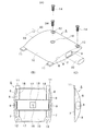
上記折りたたみ椅子の座部3の裏面には略箱状の取付ボックス5が取り付けられている。この取付ボックス5は、好ましくはプラスチック材料で成形され、図3に示すように、ほぼ矩形状に形成され、側板6が両側に起立している。該側板6は、座部3の裏面側の内辺7が、座部に沿うよう直線状でかつ中央部が外方に湾曲する形状に形成され、座部から離れる側の外辺8は、座部との間に空間を形成するよう中央部が座部の裏面から離れる方向に膨らんだ弧状に形成され、上記裏面側の内辺7よりも外辺8が内方に位置するように側板全体が傾斜している。該側板6には、座部の裏面に沿う方向に長く形成されている長孔、図に示す実施例では、内辺、外辺に沿ってストレート部を有する断面略長楕円状の貫通孔が形成されている。取付ボックスは、上記の形状により、全体が薄く形成され、かつ強度があり、折りたたみ状態の椅子を積層しても壊れにくくできる。
A substantially box-
上記取付ボックス5には、両側板6を覆うよう外面板10が形成されている。該外面板10の一端側の両端には矩形状の差し込み片11が突設されており、他端側の両端にはねじ挿通孔12が設けらている。この差し込み片11とねじ挿通孔12に対応して、上記座部3の裏面には、図2に示すように、差し込み片11が挿入されるスリット13が2箇所開口されており、ねじ14をねじ着するための埋込ナット15が埋め込まれている。また、外面板10のほぼ中央部には開口部縁をさらもみした固定用孔16が設けらている。なお、外面板10の内面には、上記貫通孔9の両端側を結ぶ横リブ17と、該横リブ17と外面板の端縁間に延びる縦リブ18が設けられ、固定用孔16の周囲には隆起部19が形成されている。
An
隣接する折りたたみ椅子の前脚1間は、一対の連結具20で連結される。該連結具20は、好ましくはプラスチック材料で成形され、略平板状の止着部21の両側に、脚挿通溝22が形成されている。上記止着部21の中央部には止着孔23が形成され、内面の隅部には2つのボス24と、対向する連結具のボスに嵌合可能がボス孔25が突設され、かつリブ26が設けられている。上記脚挿通溝22は、脚の断面形状に対応して断面半円形等の形状に形成することもできるが、図に示す実施例では折りたたみ椅子の前脚1の断面形状が扁平な断面略長楕円状に形成されているので、それに対応して断面略半長楕円状に形成してある。該脚挿通溝22を形成する壁部27の端縁には、該端縁の厚さの半分の厚さ部分で外方に延びる段部28が形成され、該段部28の外側に係合片29が突設されている。この係合片29は、段部より外方に突出する先端部分が弧状に形成され、挿入間隙30をあけて複数設けられ、この挿入間隙30は、壁部の外側に形成され底部が弧状の受溝になっている。なお、該係合片29の先端部は、少し段部側に傾いており、この傾斜により一対の連結具を合着した際に係合片は挿入間隙30に嵌合して壁部27の外面に噛み合い、かつ上記ボス24がボス孔25に嵌合することにより連結具を強固に結合させることができる。該連結具20の外面にも止着孔23の両側を囲むリブ31が設けられている。
The
上記取付ボックスに貫挿される連結パイプ32は、上記取付ボックスに設けた貫通孔9の断面形状に対応した形状に形成され、図に示す実施例では長孔状の貫通孔に対応してストレート部を有する断面略長楕円形に形成されている。上記貫通孔9及び連結パイプ32は、所望により断面円形、断面矩形その他適宜の形状に形成することもできる。実施例のように、断面略長楕円形のパイプにして短い方を座部の折りたたみ方向にすると、取付ボックス5の厚さを、丸パイプに比べて薄く形成することができ、かつ取付ボックス5と相対的に回転しないように嵌合させることができるから、折りたたみ椅子の展開、折りたたみ操作が安定し、操作性が増す。なお、連結パイプ32には、取付ボックス5に設けた固定用孔16に対応する位置にねじ孔33が設けられている。
The connecting
上記構成により、折りたたみ椅子を連結するには、座部3の裏面に設けたスリット13に取付ボックス5の差し込み片11を差し込み、ねじ挿通孔12にねじ14を差し込んで座部裏に設けた埋込ナット15にねじ着して取付ボックス5を座部3に固定する。そして、隣接する椅子の取付ボックス5の貫通孔9に連結パイプ12を連通し、固定用孔16にねじ34を通してねじ止めする。一方、隣接する椅子の前脚1の前後から2つの連結具20を当てがい、脚挿通溝22に脚1を嵌合し、各連結具20の係合片29を相手側の連結具に噛み合わせ、止着部21をねじ35とナット36でねじ止めすれば、折りたたみ椅子は、連結パイプ32と連結具20で横方向に確実に連結される。
With the above configuration, in order to connect the folding chair, the
本発明は、上記ように構成されているので、左右の折りたたみ椅子を動揺しないように確実に連結することができ、展開、収納操作が簡単である。また、組み立てるには、取付ボックスと一対の連結具で簡単に組み立てできるから、作業が容易で手早くでき、部品点数も少ないので、経済的である。 Since the present invention is configured as described above, the left and right folding chairs can be reliably connected so as not to be shaken, and the deployment and storage operations are simple. In addition, since it can be easily assembled with a mounting box and a pair of connecting devices, the operation is easy and quick, and the number of parts is small, which is economical.
1 前脚
2 後脚
3 座部
5 取付ボックス
9 貫通孔
11 差し込み片
12 ねじ挿通孔
13 スリット
15 埋込ナット
20 連結具
21 止着部
22 脚挿通溝
24 ボス
25 ボス孔
29 係合片
32 連結パイプ
DESCRIPTION OF
本発明によれば、両側板と該両側板間を覆う外面板を有する箱状の取付ボックスと、止着部の両側に脚挿通溝を形成した一対の連結具を具備し、上記取付ボックスの両側板には連結パイプを挿通する貫通孔が形成されており、上記連結具の脚挿通溝の端縁には係合片が形成されており、上記取付ボックスを折りたたみ椅子の座部の裏面に取り付け、連結パイプを貫通孔に貫通させるとともに隣接する椅子の脚を上記連結具の脚挿通溝に挿入し上記係合片を噛み合わせて止着部を締着したことを特徴とする折りたたみ椅子の連結装置が提供され、上記課題が解決される。 According to the present invention, there is provided a box-shaped mounting box having both side plates and an outer surface plate that covers between both side plates, and a pair of couplers having leg insertion grooves formed on both sides of the fastening portion. Both side plates are formed with through-holes through which the connecting pipes are inserted. Engagement pieces are formed at the edges of the leg insertion grooves of the connector, and the mounting box is attached to the back surface of the seat of the folding chair. mounting, the legs of the chair adjacent together when passing the connecting pipe into the through hole is inserted into the leg insertion groove of the connector folding, characterized in that fastened the fastening portion engaged with the engaging piece A connecting device for a chair is provided to solve the above problem.
上記取付ボックス5には、両側板6を覆うよう外面板10が形成されている。該外面板10の一端側の両端には矩形状の差し込み片11が突設されており、他端側の両端にはねじ挿通孔12が設けられている。この差し込み片11とねじ挿通孔12に対応して、上記座部3の裏面には、図2に示すように、差し込み片11が挿入されるスリット13が2箇所開口されており、ねじ14をねじ着するための埋込ナット15が埋め込まれている。また、外面板10のほぼ中央部には開口部縁をさらもみした固定用孔16が設けられている。なお、外面板10の内面には、上記貫通孔9の両端側を結ぶ横リブ17と、該横リブ17と外面板の端縁間に延びる縦リブ18が設けられ、固定用孔16の周囲には隆起部19が形成されている。
An
Claims (7)
Priority Applications (1)
| Application Number | Priority Date | Filing Date | Title |
|---|---|---|---|
| JP2016033805A JP6677529B2 (en) | 2016-02-25 | 2016-02-25 | Collapsible chair coupling device |
Applications Claiming Priority (1)
| Application Number | Priority Date | Filing Date | Title |
|---|---|---|---|
| JP2016033805A JP6677529B2 (en) | 2016-02-25 | 2016-02-25 | Collapsible chair coupling device |
Publications (2)
| Publication Number | Publication Date |
|---|---|
| JP2017148260A true JP2017148260A (en) | 2017-08-31 |
| JP6677529B2 JP6677529B2 (en) | 2020-04-08 |
Family
ID=59742022
Family Applications (1)
| Application Number | Title | Priority Date | Filing Date |
|---|---|---|---|
| JP2016033805A Active JP6677529B2 (en) | 2016-02-25 | 2016-02-25 | Collapsible chair coupling device |
Country Status (1)
| Country | Link |
|---|---|
| JP (1) | JP6677529B2 (en) |
Cited By (1)
| Publication number | Priority date | Publication date | Assignee | Title |
|---|---|---|---|---|
| WO2020148696A1 (en) * | 2019-01-17 | 2020-07-23 | Zhuhai Shichang Metals Ltd | Chair linking system |
Citations (6)
| Publication number | Priority date | Publication date | Assignee | Title |
|---|---|---|---|---|
| US1934396A (en) * | 1929-09-20 | 1933-11-07 | Lyon Metal Products Inc | Chair |
| JPS4219379Y1 (en) * | 1964-07-25 | 1967-11-09 | ||
| JPS54148513U (en) * | 1978-04-07 | 1979-10-16 | ||
| JPS58175754U (en) * | 1982-05-20 | 1983-11-24 | 宮本 茂紀 | Device for connecting chairs |
| JPS60125948U (en) * | 1984-02-01 | 1985-08-24 | 愛知株式会社 | connecting chair |
| CN202739306U (en) * | 2012-06-06 | 2013-02-20 | 黄聪杰 | Chair side-by-side connector |
-
2016
- 2016-02-25 JP JP2016033805A patent/JP6677529B2/en active Active
Patent Citations (6)
| Publication number | Priority date | Publication date | Assignee | Title |
|---|---|---|---|---|
| US1934396A (en) * | 1929-09-20 | 1933-11-07 | Lyon Metal Products Inc | Chair |
| JPS4219379Y1 (en) * | 1964-07-25 | 1967-11-09 | ||
| JPS54148513U (en) * | 1978-04-07 | 1979-10-16 | ||
| JPS58175754U (en) * | 1982-05-20 | 1983-11-24 | 宮本 茂紀 | Device for connecting chairs |
| JPS60125948U (en) * | 1984-02-01 | 1985-08-24 | 愛知株式会社 | connecting chair |
| CN202739306U (en) * | 2012-06-06 | 2013-02-20 | 黄聪杰 | Chair side-by-side connector |
Cited By (1)
| Publication number | Priority date | Publication date | Assignee | Title |
|---|---|---|---|---|
| WO2020148696A1 (en) * | 2019-01-17 | 2020-07-23 | Zhuhai Shichang Metals Ltd | Chair linking system |
Also Published As
| Publication number | Publication date |
|---|---|
| JP6677529B2 (en) | 2020-04-08 |
Similar Documents
| Publication | Publication Date | Title |
|---|---|---|
| ES2601528T3 (en) | Furniture kit | |
| KR101561174B1 (en) | Partition having connecting device | |
| US10188006B2 (en) | Bracket mount assembly for light fixtures | |
| US20110030172A1 (en) | Connecting fitting | |
| KR101735760B1 (en) | One-touch combinable cable tray using side connection clamp | |
| JP2017148260A (en) | Coupling device of folding chair | |
| KR20200020573A (en) | Structure of preventing deformation in a reading desk | |
| JP5651447B2 (en) | Wiring box | |
| JP2007037254A (en) | Wiring instrument fixture | |
| JP4863198B2 (en) | Member mounting structure and table | |
| JP5138546B2 (en) | Furniture with a top plate | |
| JP5954956B2 (en) | desk | |
| JP4803654B2 (en) | Desk with desktop panel and reinforcing member for desktop panel | |
| JP5441048B2 (en) | Gap closing member mounting structure | |
| EP2282067A1 (en) | Connecting fitting | |
| JP6062983B2 (en) | Hanger hook mounting device | |
| KR20090013978A (en) | Multi-tap with fix device | |
| JP6712533B2 (en) | Fixture and wiring connection unit | |
| JP5876707B2 (en) | desk | |
| JP6136067B2 (en) | Counter fixing structure | |
| JP5138545B2 (en) | Furniture legs | |
| KR101864764B1 (en) | socket assembly | |
| KR200258351Y1 (en) | table join structure | |
| KR200441124Y1 (en) | A fixing apparatus of pendant type lamp | |
| JP4860321B2 (en) | Panel mounting structure |
Legal Events
| Date | Code | Title | Description |
|---|---|---|---|
| A521 | Request for written amendment filed |
Free format text: JAPANESE INTERMEDIATE CODE: A523 Effective date: 20160225 |
|
| A621 | Written request for application examination |
Free format text: JAPANESE INTERMEDIATE CODE: A621 Effective date: 20190110 |
|
| A977 | Report on retrieval |
Free format text: JAPANESE INTERMEDIATE CODE: A971007 Effective date: 20200117 |
|
| A131 | Notification of reasons for refusal |
Free format text: JAPANESE INTERMEDIATE CODE: A131 Effective date: 20200129 |
|
| A521 | Request for written amendment filed |
Free format text: JAPANESE INTERMEDIATE CODE: A523 Effective date: 20200221 |
|
| TRDD | Decision of grant or rejection written | ||
| A01 | Written decision to grant a patent or to grant a registration (utility model) |
Free format text: JAPANESE INTERMEDIATE CODE: A01 Effective date: 20200303 |
|
| A61 | First payment of annual fees (during grant procedure) |
Free format text: JAPANESE INTERMEDIATE CODE: A61 Effective date: 20200313 |
|
| R150 | Certificate of patent or registration of utility model |
Ref document number: 6677529 Country of ref document: JP Free format text: JAPANESE INTERMEDIATE CODE: R150 |
|
| S533 | Written request for registration of change of name |
Free format text: JAPANESE INTERMEDIATE CODE: R313533 |
|
| R350 | Written notification of registration of transfer |
Free format text: JAPANESE INTERMEDIATE CODE: R350 |
|
| R250 | Receipt of annual fees |
Free format text: JAPANESE INTERMEDIATE CODE: R250 |
|
| R250 | Receipt of annual fees |
Free format text: JAPANESE INTERMEDIATE CODE: R250 |