JP2017147566A - hearing aid - Google Patents
hearing aid Download PDFInfo
- Publication number
- JP2017147566A JP2017147566A JP2016027231A JP2016027231A JP2017147566A JP 2017147566 A JP2017147566 A JP 2017147566A JP 2016027231 A JP2016027231 A JP 2016027231A JP 2016027231 A JP2016027231 A JP 2016027231A JP 2017147566 A JP2017147566 A JP 2017147566A
- Authority
- JP
- Japan
- Prior art keywords
- hearing aid
- antenna element
- substrate
- antenna
- ear
- Prior art date
- Legal status (The legal status is an assumption and is not a legal conclusion. Google has not performed a legal analysis and makes no representation as to the accuracy of the status listed.)
- Granted
Links
Images


Classifications
-
- H—ELECTRICITY
- H01—ELECTRIC ELEMENTS
- H01Q—ANTENNAS, i.e. RADIO AERIALS
- H01Q9/00—Electrically-short antennas having dimensions not more than twice the operating wavelength and consisting of conductive active radiating elements
- H01Q9/04—Resonant antennas
- H01Q9/30—Resonant antennas with feed to end of elongated active element, e.g. unipole
- H01Q9/42—Resonant antennas with feed to end of elongated active element, e.g. unipole with folded element, the folded parts being spaced apart a small fraction of the operating wavelength
-
- H—ELECTRICITY
- H01—ELECTRIC ELEMENTS
- H01Q—ANTENNAS, i.e. RADIO AERIALS
- H01Q1/00—Details of, or arrangements associated with, antennas
- H01Q1/27—Adaptation for use in or on movable bodies
- H01Q1/273—Adaptation for carrying or wearing by persons or animals
-
- H—ELECTRICITY
- H01—ELECTRIC ELEMENTS
- H01Q—ANTENNAS, i.e. RADIO AERIALS
- H01Q5/00—Arrangements for simultaneous operation of antennas on two or more different wavebands, e.g. dual-band or multi-band arrangements
- H01Q5/30—Arrangements for providing operation on different wavebands
- H01Q5/378—Combination of fed elements with parasitic elements
-
- H—ELECTRICITY
- H01—ELECTRIC ELEMENTS
- H01Q—ANTENNAS, i.e. RADIO AERIALS
- H01Q9/00—Electrically-short antennas having dimensions not more than twice the operating wavelength and consisting of conductive active radiating elements
- H01Q9/04—Resonant antennas
- H01Q9/16—Resonant antennas with feed intermediate between the extremities of the antenna, e.g. centre-fed dipole
- H01Q9/26—Resonant antennas with feed intermediate between the extremities of the antenna, e.g. centre-fed dipole with folded element or elements, the folded parts being spaced apart a small fraction of operating wavelength
Landscapes
- Support Of Aerials (AREA)
Abstract
Description
本開示は、補聴器に関する。 The present disclosure relates to hearing aids.
従来の補聴器は、人体の外部の送受信機との間で、アンテナを介して、データを通信可能である。従来の補聴器の1つとして、アンテナの一部がユーザの耳軸に対して平行な方向に流れるように配置され、アンテナから放射された電磁場が、その電場をユーザの頭部の表面に対して実質的に直交させつつ、ユーザの頭部の表面に沿って伝播する補聴器が知られている(特許文献1参照)。 A conventional hearing aid can communicate data with a transmitter / receiver outside the human body via an antenna. As one of the conventional hearing aids, a part of the antenna is arranged to flow in a direction parallel to the user's ear axis, and the electromagnetic field radiated from the antenna causes the electric field to be directed to the surface of the user's head. A hearing aid that propagates along the surface of the user's head while being substantially orthogonal is known (see Patent Document 1).
特許文献1に記載の補聴器では、主に耳掛型補聴器が想定されており、特に耳の内部で人体に接触又は近接した部分において、電流や電界が吸収されて放射が弱まる点の考慮が不十分である。特に耳穴型補聴器の場合、補聴器が耳の各部に接触することになるため、前述の誘電体損失の影響を受けやすくなる。
The hearing aid described in
本開示は、上記事情に鑑みてなされたものであり、耳による誘電体損失の影響を低減し、アンテナ特性を向上できる補聴器を提供する。 The present disclosure has been made in view of the above circumstances, and provides a hearing aid that can reduce the influence of dielectric loss due to ears and improve antenna characteristics.
本開示の補聴器は、基板と、基板に設けられる無線回路と、無線回路から給電を受けて動作する、開放端を含む第1の素子と、を有する。補聴器が耳穴に配置された状態において、第1の素子は、両耳を結ぶ第1の軸と、鉛直方向と平行な第2の軸と、第1の軸及び第2の軸に直交する第3の軸と、のうち少なくとも2つの軸に対して平行となる部分を含む。 The hearing aid according to the present disclosure includes a substrate, a wireless circuit provided on the substrate, and a first element including an open end that operates by receiving power from the wireless circuit. In a state where the hearing aid is disposed in the ear hole, the first element includes a first axis connecting both ears, a second axis parallel to the vertical direction, and a first axis orthogonal to the first axis and the second axis. And a portion that is parallel to at least two of the three axes.
本開示によれば、耳による誘電体損失の影響を低減し、アンテナ特性を向上できる。 According to the present disclosure, it is possible to reduce the influence of dielectric loss due to ears and improve antenna characteristics.
以下、適宜図面を参照しながら、実施形態を詳細に説明する。但し、必要以上に詳細な説明は省略する場合がある。例えば、既によく知られた事項の詳細説明や実質的に同一の構成に対する重複説明を省略する場合がある。これは、以下の説明が不必要に冗長になることを避け、当業者の理解を容易にするためである。尚、添付図面及び以下の説明は、当業者が本開示を十分に理解するために提供されるものであり、これらにより特許請求の範囲に記載の主題を限定することは意図されていない。 Hereinafter, embodiments will be described in detail with reference to the drawings as appropriate. However, more detailed description than necessary may be omitted. For example, detailed descriptions of already well-known matters and repeated descriptions for substantially the same configuration may be omitted. This is to avoid the following description from becoming unnecessarily redundant and to facilitate understanding by those skilled in the art. The accompanying drawings and the following description are provided to enable those skilled in the art to fully understand the present disclosure, and are not intended to limit the claimed subject matter.
(第1の実施形態)
[補聴器の構成]
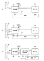
図1(A),(B)は、第1の実施形態に係る補聴器1の構成例を示す図である。図1(A)は平面斜視図を示し、図1(B)は筐体の右側(後述する表面側)を開放した側面図である。図2は、補聴器1の基板20及びアンテナ素子30の一例を示す展開図である。図3は、補聴器1の通信に係る電気的構成例を示すブロック図である。
(First embodiment)
[Configuration of hearing aid]
1A and 1B are diagrams illustrating a configuration example of a
本実施形態では、本体部3の各面に関して、図1(A)における符号3aの面を「後面」、符号3bの面を「前面」、符号3cの面を「表面」、符号3dの面を「裏面」、符号3eの面を「上面」、符号3fの面を「下面」、と便宜上定義する。
In the present embodiment, for each surface of the
補聴器1は、例えば、耳穴(外耳道)に配置される耳穴型補聴器である。補聴器1は、例えば樹脂製の筐体2を有する。補聴器1は、本体部3、音声出力部4、充電端子部5、及びマイク収音部6を備える。
The
本体部3は、例えば略楕円体の形状を有する。本体部3の内部には、補聴器1の電源であるバッテリ10と、マイク11と、レシーバ12と、基板20と、基板20と電気的に接続され屈曲可能なアンテナ素子30と、が収納される。充電端子部5の内部には、複数の充電端子13が設けられる。基板20とアンテナ素子30とは、基板20とアンテナ素子30との接続位置近傍で、略180度に折り曲げられ、折り曲げ部40を形成して本体部3に収納される。基板20には、各種電子部品が実装される。
The
音声出力部4は、例えば略円筒形の形状を有する。音声出力部4は、本体部3の一部から所定角度で突出する。音声出力部4は、その先端が鼓膜に対応して外耳道内に挿入される。音声出力部4は、本体部3よりも鼓膜側に突出する。音声出力部4は、例えば信号処理された音声信号を、レシーバ12から鼓膜側へ音声出力する。
The
充電端子部5は、例えば略円筒形の形状を有し、本体部3よりも対耳珠側に突出する。充電端子部5は、外部電源からバッテリ10へ電力を供給する。
The
マイク収音部6は、例えば、充電端子部5が本体部3から突出する位置の近傍に配置され、本体部3の側面に形成される。マイク収音部6は、マイクロホンを含み、外部の収音し、収音された音声データを本体部3の電子部品へ送る。
The microphone
アンテナ素子30は、少なくとも第1のアンテナ素子31を含む。アンテナ素子30は、第2のアンテナ素子32や第3のアンテナ素子33を含んでもよい。基板20には、少なくともRF−IC(Radio Frequency Integrated Circuit)24及び整合回路22が実装される。また、基板20には、平衡・不平衡変換回路23が実装されてもよい。整合回路22、平衡・不平衡変換回路23、及びRF−IC24は、例えば、基板20の表面3c側に実装される。
The
図3では、基板20に平衡・不平衡変換回路23が実装される。整合回路22及び平衡・不平衡変換回路23のグランドは、基板20のグランド20gに接続される。基板20のグランド20gは、基板20の面のほぼ全面又は一部にわたって形成される。
In FIG. 3, a balanced /
整合回路22と平衡・不平衡変換回路23との接続部分は、アンテナ素子30へ給電するための給電点25(図中○Nで示す)を含み、折り曲げ部40近傍に配置されてもよい。
A connection portion between the
第1のアンテナ素子31と第2のアンテナ素子32は、それぞれ開放端31a,32aを有する。各開放端31a,32aは、例えば、給電点25から離間し、本体部3の前面3b、上面3e又は下面3f近傍に配置される。
The
[給電構成]
次に、補聴器1の給電構成例について説明する。補聴器1の給電構成例には、様々なバリエーションがある。アンテナ素子30の配置例と給電構成例との対応については後述する。
[Power supply configuration]
Next, a power supply configuration example of the
図4(A)〜(C)は、RF−IC24が不平衡回路である場合の給電構成例を示すブロック図である。
4A to 4C are block diagrams illustrating an example of a power supply configuration when the RF-
図4(A)は、第1給電構成例を示す。第1給電構成例では、アンテナ素子30が第1のアンテナ素子31であり、1つである。また、RF−IC24が、基板20のグランド20gと第1のアンテナ素子31との間に不平衡給電する。
FIG. 4A illustrates a first power supply configuration example. In the first power supply configuration example, the
基板20には、整合回路22及びRF−IC24が実装される。第1のアンテナ素子31には、整合回路22が電気的に接続される。整合回路22には、RF−IC24が電気的に接続される。整合回路22及びRF−IC24のグランドは、基板20のグランド20gに接続される。
A matching
整合回路22は、アンテナ素子30側とRF−IC24側とのインピーダンスを整合する。整合回路22とRF−IC24との間の伝送線路の特性インピーダンスが、例えば50Ωに整合される。第1のアンテナ素子31の開放端31aでは、電波を放射すべくインピーダンスが例えば50Ωよりも高くなっている。給電点25は、整合回路22におけるRF−IC24との接続部分に位置する。
The matching
図4(B)は、第2給電構成例を示す。第2給電構成例では、アンテナ素子30が第1のアンテナ素子31と第2のアンテナ素子32とを有する。また、RF−IC24は、基板20のグランドと第1のアンテナ素子31との間に不平衡給電する。また、第2のアンテナ素子32は、基板20のグランド20gに接続される。
FIG. 4B illustrates a second power supply configuration example. In the second power feeding configuration example, the
基板20には、整合回路22及びRF−IC24が実装される。アンテナ素子31,32には、整合回路22が電気的に接続される。整合回路22には、RF−IC24が電気的に接続される。整合回路22のグランド、及びRF−IC24のグランドは、基板20のグランド20gに接続される。
A matching
整合回路22は、アンテナ素子30側とRF−IC24側とのインピーダンスを整合する。例えば、整合回路22とRF−IC24との間の伝送線路の特性インピーダンスが、例えば50Ωに整合される。第1のアンテナ素子31の開放端31a及び第2のアンテナ素子32の開放端32aでは、電波を放射すべくインピーダンスが例えば50Ωよりも高くなっている。給電点25は、整合回路22におけるRF−IC24との接続部分に位置する。
The matching
図4(C)は、第3給電構成例を示す。第3給電構成例は、図3と同様の構成を有する。第3給電構成例では、アンテナ素子30が第1のアンテナ素子31と第2のアンテナ素子32とを有する。また、RF−IC24は、平衡・不平衡変換回路23を介して第1のアンテナ素子31と第2のアンテナ素子32との間に平衡給電する。
FIG. 4C illustrates a third power feeding configuration example. The third power supply configuration example has a configuration similar to that of FIG. In the third power feeding configuration example, the
基板20には、整合回路22、RF−IC24、及び平衡・不平衡変換回路23が実装される。アンテナ素子31,32には、整合回路22が電気的に接続される。整合回路22には、平衡・不平衡変換回路23が電気的に接続される。平衡・不平衡変換回路23には、RF−IC24が電気的に接続される。平衡・不平衡変換回路23のグランド及びRF−IC24のグランドは、基板20のグランド20gに接続される。
A matching
整合回路22は、アンテナ素子30側と平衡・不平衡変換回路23及びRF−IC24側とのインピーダンスを整合する。例えば、整合回路22と平衡・不平衡変換回路23とRF−IC24との間の伝送線路の特性インピーダンスが、例えば50Ωに整合される。第1のアンテナ素子31の開放端31a及び第2のアンテナ素子32の開放端32aでは、電波を放射すべくインピーダンスが50Ωよりも高くなっている。給電点25は、整合回路22における平衡・不平衡変換回路23との接続部分に位置する。
The matching
図5(A)〜(C)は、RF−IC24が平衡回路である場合の給電構成例を示すブロック図である。
FIGS. 5A to 5C are block diagrams illustrating power supply configuration examples in the case where the RF-
図5(A)は、第4給電構成例を示す。第4給電構成例では、アンテナ素子30が第1のアンテナ素子31であり、1つである。また、RF−IC24が、平衡・不平衡変換回路23を介して基板20のグランド20gと第1のアンテナ素子31との間に不平衡給電する。
FIG. 5A illustrates a fourth power feeding configuration example. In the fourth power feeding configuration example, the
基板20には、整合回路22、平衡・不平衡変換回路23、及びRF−IC24が実装される。第1のアンテナ素子31には、整合回路22が電気的に接続される。整合回路22には、平衡・不平衡変換回路23が電気的に接続される。平衡・不平衡変換回路23には、RF−IC24が電気的に接続される。整合回路22のグランド、平衡・不平衡変換回路23のグランド、及びRF−IC24のグランドは、基板20のグランド20gに接続される。
A matching
整合回路22は、アンテナ素子30側と平衡・不平衡変換回路23及びRF−IC24側とのインピーダンスを整合する。例えば、整合回路22と平衡・不平衡変換回路23及びRF−IC24との間の伝送線路の特性インピーダンスが、例えば50Ωに整合される。第1のアンテナ素子31の開放端31aでは、電波を放射すべくインピーダンスが例えば50Ωよりも高くなっている。給電点25は、整合回路22における平衡・不平衡変換回路23との接続部分に位置する。
The matching
図5(B)は、第5給電構成例を示す。第5給電構成例では、アンテナ素子30が第1のアンテナ素子31と第2のアンテナ素子32とを有する。また、RF−IC24は、平衡・不平衡変換回路23を介して基板20のグランド20gと第1のアンテナ素子31との間に不平衡給電する。また、第2のアンテナ素子32は、基板20のグランド20gに接続される。
FIG. 5B shows a fifth power feeding configuration example. In the fifth power feeding configuration example, the
基板20には、整合回路22、平衡・不平衡変換回路23、及びRF−IC24が実装される。アンテナ素子31,32には、整合回路22が電気的に接続される。整合回路22には、平衡・不平衡変換回路23が電気的に接続される。平衡・不平衡変換回路23には、RF−IC24が電気的に接続される。整合回路22のグランド、平衡・不平衡変換回路23のグランド、及びRF−IC24のグランドは、基板20のグランド20gに接続される。
A matching
整合回路22は、アンテナ素子30側と平衡・不平衡変換回路23及びRF−IC24側とのインピーダンスを整合する。例えば、整合回路22と平衡・不平衡変換回路23及びRF−IC24との間の伝送線路の特性インピーダンスが、例えば50Ωに整合される。第1のアンテナ素子31の開放端31a及び第2のアンテナ素子32の開放端32aでは、電波を放射すべくインピーダンスが例えば50Ωよりも高くなっている。給電点25は、整合回路22における平衡・不平衡変換回路23との接続部分に位置する。
The matching
図5(C)は、第6給電構成例を示す。第6給電構成例では、アンテナ素子30が第1のアンテナ素子31と第2のアンテナ素子32とを有する。また、RF−IC24は、第1のアンテナ素子31と第2のアンテナ素子32との間に平衡給電する。
FIG. 5C illustrates a sixth power feeding configuration example. In the sixth power feeding configuration example, the
基板20には、整合回路22及びRF−IC24が実装される。アンテナ素子31,32には、整合回路22が電気的に接続される。整合回路22には、RF−IC24が電気的に接続される。RF−IC24のグランドは、基板20のグランド20gに接続される。
A matching
整合回路22は、アンテナ素子30側とRF−IC24側とのインピーダンスを整合する。例えば、整合回路22とRF−IC24との間の伝送線路の特性インピーダンスが、例えば50Ωに整合される。第1のアンテナ素子31の開放端31a及び第2のアンテナ素子32の開放端32aでは、電波を放射すべくインピーダンスが例えば50Ωよりも高くなっている。給電点25は、整合回路22におけるRF−IC24との接続部分に位置する。
The matching
図6(A)〜(C)は、各給電構成例をより概念的に示す図である。図6(A)は、第1給電構成例及び第4給電構成例を概念的に示す。図6(B)は、第2給電構成例及び第5給電構成例を概念的に示す。図6(C)は、第3給電構成例及び第6給電構成例を概念的に示す。 6A to 6C are diagrams conceptually showing each power supply configuration example. FIG. 6A conceptually shows a first power supply configuration example and a fourth power supply configuration example. FIG. 6B conceptually illustrates a second power supply configuration example and a fifth power supply configuration example. FIG. 6C conceptually shows a third power feeding configuration example and a sixth power feeding configuration example.
[外耳の構成]
次に、外耳の構成について説明する。
[Configuration of outer ear]
Next, the configuration of the outer ear will be described.
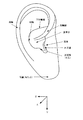
図7は、耳の外耳部分を説明するための模式図である。耳の中央部で窪んだ部分を耳甲介という。外耳道を外から部分的に覆う場所を耳珠という。対輪の下部に位置し耳甲介の一部を覆う部分を対耳珠という。 FIG. 7 is a schematic diagram for explaining an outer ear portion of an ear. The concave part in the center of the ear is called the concha. A place that partially covers the external auditory canal is called tragus. The part that is located at the lower part of the opposite wheel and covers a part of the concha is called the anti-tragus.
本実施形態では、両耳を結ぶ軸(耳軸)に平行な軸を、第1の軸Xとする。ユーザが起立姿勢又は着座姿勢(耳により定義される面が鉛直方向に沿う姿勢)において、鉛直方向と平行な軸を、第2の軸Yとする。第1の軸X及び第2の軸Yに直交する軸を、第3の軸Zとする。よって、第1の軸X、第2の軸Y及び第3の軸Zは、3次元空間上で直交する。尚、第2の軸Yは、耳垂が延びる方向に平行な軸とも言える。 In the present embodiment, the first axis X is an axis parallel to the axis connecting both ears (ear axis). When the user is in a standing posture or a sitting posture (a posture defined by the ears is a posture along the vertical direction), an axis parallel to the vertical direction is defined as a second axis Y. An axis orthogonal to the first axis X and the second axis Y is defined as a third axis Z. Therefore, the first axis X, the second axis Y, and the third axis Z are orthogonal in a three-dimensional space. The second axis Y can also be said to be an axis parallel to the direction in which the earlobe extends.
図8は、耳に補聴器1が配置された状態での耳と補聴器1の各部との位置関係を示す模式図である。
FIG. 8 is a schematic diagram showing the positional relationship between the ear and each part of the
補聴器1が耳に配置されると、耳の一部は、補聴器1の一部(例えば補聴器1の本体部3、充電端子部5)に当接する。補聴器1が耳に挿入されると、例えば、補聴器1の表面3cは、耳珠(図8のA部参照)に接し得る。補聴器1の前面3bに近い上面3eは、外耳道の上部にある耳輪脚(図8B参照)に接し得る。補聴器1の後面3aに近い上面3eは、下対輪脚(図8C参照)に接し得る。後面3aは、耳輪(図8D参照)と接し得る。充電端子部5は、対耳珠(図8E参照)に接し得る。裏面3dは、耳甲介と接し得る。また、充電端子部5の先端は、対耳珠(図7参照)に支持される。
When the
以後、これら補聴器1のいずれかの面と接し得る部位を、「耳壁」とも称する。
Hereinafter, the part that can come into contact with any surface of these
尚、上記の補聴器1と耳との当接関係は一例であり、例えば耳の大きさや補聴器1のサイズに依存して、補聴器1と耳との当接位置は変化し得る。
The contact relationship between the
[給電点の位置の考察]
図9は、各アンテナ素子30近傍での電流A、電界E、電流密度Jを説明するための模式図である。
[Consideration of feeding point position]
FIG. 9 is a schematic diagram for explaining the current A, the electric field E, and the current density J in the vicinity of each
ここでは、給電点25を介して2つのアンテナ素子間に給電される場合の電流A、電界E、及び電流密度Jを示す。2つのアンテナ素子30は、第1のアンテナ素子31及び第2のアンテナ素子32でもよいし、第1のアンテナ素子及び第3のアンテナ素子でもよい。また、第2のアンテナ素子32の代わりに、基板20のグランド20gでもよい。図9では、2つのアンテナ素子30が、第1のアンテナ素子31及び第2のアンテナ素子32であることを例示している。
Here, a current A, an electric field E, and a current density J when power is supplied between two antenna elements via a
図9では、電流密度Jは、給電点25で最大となり、各アンテナ素子30の開放端(例えば開放端31a,32a)で最小となる。
In FIG. 9, the current density J is maximum at the
補聴器1が耳に配置された場合、補聴器1が耳壁と近接すると、電流A又は電界Eの少なくとも一部が吸収されることがある。例えば、開放端31a,32aの中間の領域(内側の領域、近傍の領域)R1に耳壁が近接すると、電界Eが吸収されることで、電気的損失が増大する。給電点25の近傍の領域R2に耳壁が近接すると、電流Aが吸収されることで、電気的損失が増大する。一方、各アンテナ素子30の外側の領域R3に耳壁が近接しても、電界Eが遮られず、電流Aも小さいため、電気的損失に係る影響は少ない。耳壁(人体)は、誘電体の1つである。
When the
補聴器1では、図10に示すように、給電点25は、折り曲げ部40の近傍に配置される。即ち、給電点25は、本体部3の内面から離間し、つまり耳壁から離間し、本体部3内部の後面3a側に配置される。よって、給電点25に対する耳壁の位置は、領域R2よりも給電点25から離れた位置となり、電気的損失が低減される。
In the
また、給電点25は、第1の軸Xに沿う第1の方向(表裏方向)では、本体部3において鼓膜側と反対側(表面3c側)に含まれることが好ましい。給電点25は、第2の軸Yに沿う第2の方向(上下方向)では、本体部3の中心付近に含まれることが好ましい。給電点25は、第3の軸Zに沿う第3の方向(前後方向)では、本体部3において耳輪側(後面3a側)に含まれることが好ましい。つまり、耳への装着状態において、給電点25は、外耳道の入口側(第3の軸Zの正側)に配置されてもよい。また、耳への装着状態において、給電点25は、音声出力部4と反対側に設けられてもよい。これにより、給電点25は、各耳壁面から離間され、アンテナ特性の劣化を抑制できる。
In addition, the
このように、図10に示したアンテナ素子30の配置により、補聴器1は、電流A、電界E等が耳壁に吸収されて放射が弱まることを抑制できる。
Thus, by arrangement | positioning of the
[アンテナ素子の配置の考察]
図11(A),(B)は、比較例の鏡像効果による電界Eの相殺を説明するための説明図である。図11(A)は、比較例における耳へ補聴器が装着された状態での各アンテナ素子の配置を示す側面図である。図11(B)は、比較例における電界Eを説明する模式図である。符号120は、基板を示す。
[Consideration of antenna element arrangement]
11A and 11B are explanatory diagrams for explaining the cancellation of the electric field E by the mirror image effect of the comparative example. FIG. 11A is a side view showing the arrangement of the antenna elements in a state where the hearing aid is attached to the ear in the comparative example. FIG. 11B is a schematic diagram illustrating the electric field E in the comparative example.
図11(A)では、2つのアンテナ素子131,132は、耳甲介により定義される面と略平行なYZ面(図7参照)に沿って配置され、2つのアンテナ素子131,132間に給電点125が設けられている。
In FIG. 11A, the two
電流Aがアンテナ素子132からアンテナ素子131へ流れる場合、電界Eは、アンテナ素子131からアンテナ素子132の方向となる。一方、人体内では鏡像により、鏡像電流A1が電流Aとは反対方向に流れ、鏡像電流A1に基づく鏡像電界E1も電界Eとは反対方向となる。
When the current A flows from the
よって、比較例では、電界Eは、鏡像電界E1により相殺され、アンテナ効率の低下に繋がる。 Therefore, in the comparative example, the electric field E is canceled by the mirror image electric field E1, which leads to a decrease in antenna efficiency.
図12(A),(B)は、本実施形態の鏡像効果による電界Eの相殺の低減を説明する模式図である。図12(A)は、耳へ装着された補聴器1を表面3c側から見た場合のアンテナ素子30の延在方向の一例を示す模式図を示す。図12(B)は、図12(A)の電流A及び鏡像電流A1,A2を説明する模式図である。
FIGS. 12A and 12B are schematic diagrams for explaining the reduction of the cancellation of the electric field E by the mirror image effect of the present embodiment. FIG. 12A is a schematic diagram illustrating an example of the extending direction of the
ここでは、アンテナ素子30は、第1のアンテナ素子31及び第2のアンテナ素子32でもよいし、第1のアンテナ素子31及び第3のアンテナ素子33でもよい。また、第2のアンテナ素子32の代わりに、基板20のグランド20gでもよい。
Here, the
図12(A)では、2つのアンテナ素子30が、第1のアンテナ素子31及び基板20のグランド20gであることを例示しており、第1のアンテナ素子31の延在方向を考察する。尚、第1のアンテナ素子31の延在方向は、これに限られない。
FIG. 12A illustrates that the two
図12(A)では、第1のアンテナ素子31は、給電点25付近では第1の軸Xに沿う部分PAと、基板20の表面3c側では第3の軸Zに沿う部分PBと、を有する。この場合、部分PAは、本体部3の裏面3d側に沿う耳壁面MAに対して直交する。部分PBは、本体部3の後面3a側に沿う耳壁面MBに対して直交する。
12A, the
耳壁面MA,MBに対してそれぞれ鏡像電流を考察すると、図12(B)のようになる。第1のアンテナ素子31の部分PAについて考察すると、耳壁面MAに対しては、鏡像効果により、電流Aの成分Apaと同じ向きに、鏡像電流A1の成分A1paが生じる。よって、電流Aの成分Apaは、鏡像電流A1の成分A1paと同じ向きとなり、相互に強め合う。一方、耳壁面MBに対しては、鏡像効果により、電流Aの成分Apaと反対の向きに、鏡像電流A2の成分A2paが生じる。よって、電流Aの成分Apaは、耳壁面MBによる鏡像電流A2の成分A2paと反対の向きとなり、相互に弱め合う。
When the mirror image current is considered for each of the ear wall surfaces MA and MB, it is as shown in FIG. Considering the portion PA of the
また、第1のアンテナ素子31において部分PAとともに部分PBを考慮すると、耳壁面MBに対して、鏡像効果により、電流Aの成分Apbと同じ向きに、鏡像電流A2の成分A2pbが生じる。よって、電流Aの成分Apbは、耳壁面MBによる鏡像電流A2の成分A2paと同じ向きとなり、相互に強め合う。
Further, when considering the portion PB together with the portion PA in the
このように、アンテナ素子30が複数の耳壁面に直交する成分を有することで、アンテナ素子30が延びる複数の方向に対して、鏡像効果により電流Aを相互に強め合う成分を含むことができる。これにより、補聴器1は、各耳壁面に直交する電流Aの各成分及び電流Aの各成分に応じた各電界Eの成分を増大できる。よって、補聴器1は、鏡像電流及び鏡像電界によって実空間上の電流A及び電界Eが相殺されることを低減でき、アンテナ効率の低下を抑制できる。
As described above, since the
[アンテナ素子の配置]
次に、アンテナ素子30の配置例について説明する。
[Arrangement of antenna elements]
Next, an arrangement example of the
図13(A),(B)は、アンテナ素子30の第1配置例を示す。図13(A)は、耳に補聴器1が装着されていない状態(非装着状態)を示す。図13(B)は、耳に補聴器1が装着された状態(装着状態)を示す。
13A and 13B show a first arrangement example of the
第1配置例では、第1のアンテナ素子31は、給電点25を介して基板20のグランド20gに接地している。つまり、第1配置例での補聴器1の給電に係る構成は、図6(A)に示した第1給電構成例又は第4給電構成例に相当する。
In the first arrangement example, the
第1配置例では、RF−IC24が実装された基板20が、表面3c,裏面3d(YZ面)に略平行となるように配置される。給電点25は、本体部3の前後方向において、中央よりも後面3a側に配置される。給電点25は、本体部3の上下方向において、本体部3の中央付近に配置される。給電点25は、本体部3の表裏方向において、中央より表面3c側に配置される。第1のアンテナ素子31の開放端31aは、本体部3の表面3c及び後面3aに沿って配置される。
In the first arrangement example, the
第1のアンテナ素子31は、給電点25付近において、基板20の面に対して垂直となる部分を有する。第1のアンテナ素子31の一部又は全ては、基板20の面と直交する位置に配置される。図13(A)では、第1のアンテナ素子31は、基板20の一端から折り曲げ部40で屈曲し、基板20の面に沿って配置されている。よって、第1のアンテナ素子31は、3つの軸(第1の軸X、第2の軸Y及び第3の軸Z)に沿う部分を含む。
The
図14(A),(B)は、アンテナ素子30の第2配置例を示す。図14(A)は、補聴器1の非装着状態を示す。図14(B)は、補聴器1の装着状態を示す。
14A and 14B show a second arrangement example of the
第2配置例では、アンテナ素子30の本数、給電に係る構成及び基板20の配置は、図13(A),(B)に示した第1配置例と同様である。第2配置例では、第1のアンテナ素子31は、折り曲げ部40から基板20を一部覆う状態で、本体部3の上下方向の略中央から上面3e方向に折れ曲がり、更に前面3b方向に向かって折れ曲がっている。よって、第2配置例では、第1のアンテナ素子31は、3つの軸(第1の軸X、第2の軸Y及び第3の軸Z)に沿う部分を含む。
In the second arrangement example, the number of
第1配置例又は第2配置例の補聴器1によれば、電流Aが集中する給電点25が各耳壁から離間するので、人体近接による誘電体損失を低減できる。
According to the
また、アンテナ素子30(例えば第1のアンテナ素子31)における開放端(例えば開放端31a)には電流Aが集中し難いため、給電点25に比較して人体近接による影響が小さい。従って、補聴器1は、アンテナ素子30が耳壁に近接しても、アンテナ体積を拡大することで、アンテナ利得の向上と人体近接による利得劣化の低減を両立できる。尚、アンテナ体積とは、例えば、アンテナ素子30が配置される場合の基板20のグランド20gとアンテナ素子30との間を含めた空間の体積を指す。
In addition, since the current A is difficult to concentrate at the open end (for example, the
また、補聴器1では、アンテナ素子30と基板20のグランド20gとによる電界Eが、耳壁と直交した成分となる部分を多く含む。よって、補聴器1は、鏡像効果による電界Eの相殺を低減でき、アンテナ利得劣化を抑制できる。
Moreover, in the
図15(A)〜(C)は、アンテナ素子30の第3配置例を示す。図15(A)は、補聴器1内部を表面3c側から見た模式図であり、非装着状態を示す。図15(B)は、補聴器1内部を後面3a側から見た模式図であり、非装着状態を示す。図15(C)は、補聴器1内部を表面3c側から見た模式図であり、装着状態を示す。
15A to 15C show a third arrangement example of the
第3配置例では、第1配置例と比較すると、本体部3の内部に第2のアンテナ素子32が設けられている。第2のアンテナ素子32は、基板20の裏面3d側から、本体部3の裏面3dに向かって突出し、下面3fに向かって延在して配置されている。第2のアンテナ素子32の一部又は全ては、基板20に対して第1のアンテナ素子31とは反対側に配置される。
In the third arrangement example, the
第3配置例での補聴器1の給電に係る構成は、図6(B)又は図6(C)に示した構成であり、第2給電構成例、第3給電構成例、第5給電構成例、又は第6給電構成例に相当する。よって、RF−IC24は、第1のアンテナ素子31及び第2のアンテナ素子32との間に平衡又は不平衡に給電する。
The configuration relating to the power supply of the
図16(A)〜(C)は、アンテナ素子30の第4配置例を示す。図16(A)は、補聴器1内部を表面3c側から見た模式図であり、非装着状態を示す。図16(B)は、補聴器1内部を後面3a側から見た模式図であり、非装着状態を示す。図16(C)は、補聴器1内部を表面3c側から見た模式図であり、装着状態を示す。
16A to 16C show a fourth arrangement example of the
第4配置例では、アンテナ素子30の本数、給電に係る構成及び基板20の配置は、図15(A)〜(C)に示した第3配置例と同様である。第4配置例では、第1のアンテナ素子31の延在方向が、第2配置例と同様である。つまり、第1のアンテナ素子31は、折り曲げ部40から基板20を一部覆う状態で、本体部3の上下方向の略中央から上面3e方向に折れ曲がり、更に前面3b方向に向かって折れ曲がっている。
In the fourth arrangement example, the number of
第3配置例及び第4配置例の補聴器1によれば、電流Aが最大となる給電点25の位置を変えずに、基板20のグランド20gと第1のアンテナ素子31との間隔と比較して、第1のアンテナ素子31と第2のアンテナ素子32との間隔を拡大できる。従って、アンテナ体積を拡大でき、人体近接での電流Aの吸収による劣化を更に抑制できる。
According to the
図17(A),(B)は、アンテナ素子30の第5配置例を示す。図17(A)は、補聴器1の非装着状態を示す。図17(B)は、補聴器1の装着状態を示す。
17A and 17B show a fifth arrangement example of the
第5配置例では、アンテナ素子30には、第1のアンテナ素子31及び第2のアンテナ素子32が含まれる。第1のアンテナ素子31は、折り曲げ部40から基板20の表面3c側に折れ曲がり、基板20の表面3c側において、略十字形状を有している。第2のアンテナ素子32は、折り曲げ部40から、基板20の表面3c側に折れ曲がり、第1のアンテナ素子31に沿う箇所がある。また、第2のアンテナ素子32は、本体部3の上下方向の略中央から上面3e方向に折れ曲がり、更に基板20に対して裏面3d側で前面3b方向に向かって折れ曲がっている。
In the fifth arrangement example, the
第5配置例での補聴器1の給電に係る構成は、図6(B)又は図6(C)に示した構成であり、第2給電構成例、第3給電構成例、第5給電構成例、又は第6給電構成例に相当する。よって、RF−IC24は、第1のアンテナ素子31及び第2のアンテナ素子32との間に平衡又は不平衡に給電する。
The configuration related to the power supply of the
尚、第5配置例では、第1のアンテナ素子31と第2のアンテナ素子32との配列は逆でもよい。
In the fifth arrangement example, the arrangement of the
第5配置例の補聴器1によれば、第1配置例及び第2配置例と比較すると、第1のアンテナ素子31と第2のアンテナ素子32との間隔を拡大できる。よって、補聴器1は、人体に直交する電界E成分をより大きくできるので、アンテナ利得を向上できる。
According to the
また、補聴器1は、基板20の裏面3d側におけるアンテナ素子30(第1のアンテナ素子31及び第2のアンテナ素子32)の占有体積を低減できる。従って、補聴器1は、基板20の裏面3d側に、他の部品を搭載するスペースを確保し易くできる。
In addition, the
図18(A)〜(C)は、アンテナ素子30の第6配置例を示す。図18(A)は、補聴器1内部を表面3c側から見た模式図であり、非装着状態を示す。図18(B)は、補聴器1内部を後面3a側から見た模式図であり、非装着状態を示す。図18(C)は、補聴器1内部を表面3c側から見た模式図であり、装着状態を示す。
18A to 18C show a sixth arrangement example of the
第6配置例の補聴器1は、第5配置例と同様の構成を有する。第6配置例の補聴器1は、第5配置例と比較して、アンテナ素子30が、第1のアンテナ素子31及び第2のアンテナ素子32とともに、第3のアンテナ素子33を有する。
The
第3のアンテナ素子33は、基板20の裏面3d側から、本体部3の裏面3dに向かって突出し、下面3fに向かって延在して配置されている。第3のアンテナ素子33の一部又は全ては、基板20に対して第1のアンテナ素子31とは反対側に配置される。
The
RF−IC24は、第1のアンテナ素子31及び第2のアンテナ素子32の間に、平衡又は不平衡に給電してもよい。第3のアンテナ素子33は、無給電素子として動作する。
The RF-
ここで、図19(A)〜(D)は、第1のアンテナ素子31、第2のアンテナ素子32、及び第3のアンテナ素子33を含む補聴器1の給電構成例(第7〜第10給電構成例)を概念的に示す概念図である。
Here, FIGS. 19A to 19D show power supply configuration examples of the
第7〜第10給電構成例では、RF−IC24は、給電点25を介して、基板20のグランドと第1のアンテナ素子31との間に不平衡給電する。
In the seventh to tenth power supply configuration examples, the RF-
図19(A)は、第7給電構成例を示す。第7給電構成例では、第3のアンテナ素子33は、第2のアンテナ素子32と電磁結合(容量結合)し、無給電素子として動作する。
FIG. 19A shows a seventh power feeding configuration example. In the seventh power supply configuration example, the
図19(B)は、第8給電構成例を示す。第8給電構成例では、第3のアンテナ素子33は、第1のアンテナ素子31と電磁結合し、無給電素子として動作する。
FIG. 19B shows an eighth power feeding configuration example. In the eighth feeding configuration example, the
図19(C)は、第9給電構成例を示す。第9給電構成例では、第3のアンテナ素子33は、基板20のグランドと第1のアンテナ素子31との接続点近傍に接地されることで、無給電素子として動作する。
FIG. 19C shows a ninth power feeding configuration example. In the ninth power supply configuration example, the
図19(D)は、第10給電構成例を示す。第10給電構成例では、第3のアンテナ素子33は、基板20のグランドと第2のアンテナ素子32との接続点近傍に接地されることで、無給電素子として動作する。
FIG. 19D illustrates a tenth power supply configuration example. In the tenth power supply configuration example, the
尚、図19(A)〜(D)では、不平衡給電時の例を示すが、平衡給電時でも同様である。 FIGS. 19A to 19D show an example of unbalanced power supply, but the same applies to balanced power supply.
第6配置例での補聴器1によれば、補聴器1は、第3のアンテナ素子33を無給電素子として第1のアンテナ素子31及び第2のアンテナ素子32が共振している周波数とは異なる周波数で共振させることで、通信帯域を拡大できる。また、補聴器1は、第3のアンテナ素子33を用いて第2のアンテナ素子32を等価的に大きくできる。従って、補聴器1は、人体による電流Aや電界Eの吸収を低減できる。
According to the
尚、第6配置例では、第2のアンテナ素子32と第3のアンテナ素子33との配列は逆でもよい。
In the sixth arrangement example, the arrangement of the
図20(A),(B)は、アンテナ素子30の第7配置例を示す。図20(A)は、補聴器1の非装着状態を示す。図20(B)は、補聴器1の装着状態を示す。
20A and 20B show a seventh arrangement example of the
第7配置例では、アンテナ素子30の配置及び補聴器1の給電に係る構成は、第3配置例と同様である。また、バッテリ10の構造材の少なくとも一部が、第2のアンテナ素子32の少なくとも一部として動作する。バッテリ10は、基板20に対して本体部3の裏面3d側に配置される。
In the seventh arrangement example, the arrangement relating to the arrangement of the
図21(A),(B)は、アンテナ素子30の第8配置例を示す。図21(A)は、補聴器1の非装着状態を示す。図21(B)は、補聴器1の装着状態を示す。
21A and 21B show an eighth arrangement example of the
第8配置例では、アンテナ素子30の配置及び補聴器1の給電に係る構成は、第4配置例と同様である。また、バッテリ10の構造材の少なくとも一部が、第2のアンテナ素子32の少なくとも一部として動作する。バッテリ10は、基板20に対して本体部3の裏面3d側に配置される。
In the eighth arrangement example, the arrangement relating to the arrangement of the
尚、第7配置例及び第8配置例では、図21(C)に示すように、バッテリ10の構造材の少なくとも一部は、バッテリ10の電池端子10aや電池端子10aと基板20のグランド20gとを接続するパターン10bを含んでもよい。
In the seventh arrangement example and the eighth arrangement example, as shown in FIG. 21C, at least a part of the structural material of the
第7配置例又は第8配置例の補聴器1によれば、第2のアンテナ素子32をバッテリ10と共用することで、アンテナ専用スペースやアンテナ専用部品を削減でき、補聴器1の小型化及び低コスト化を実現できる。
According to the
図22(A)〜(C)は、アンテナ素子30の第9配置例を示す。図22(A)は、補聴器1内部を表面3c側から見た模式図であり、非装着状態を示す。図22(B)は、補聴器1内部を後面3a側から見た模式図であり、非装着状態を示す。図22(C)は、補聴器1内部を表面3c側から見た模式図であり、装着状態を示す。
22A to 22C show a ninth arrangement example of the
第9配置例では、アンテナ素子30の配置及び補聴器1の給電に係る構成は、第6配置例と同様である。また、バッテリ10の構造材の少なくとも一部が、第3のアンテナ素子33の少なくとも一部として動作する。バッテリ10は、基板20に対して本体部3の裏面3d側に配置される。
In the ninth arrangement example, the arrangement relating to the arrangement of the
第9配置例の補聴器1によれば、第3のアンテナ素子33をバッテリ10と共用することで、アンテナ専用スペースやアンテナ専用部品を削減でき、補聴器1の小型化及び低コスト化を実現できる。
According to the
[効果等]
このように、補聴器1は、基板20と、基板20に設けられる無線回路と、無線回路から給電を受けて動作する、開放端を含む第1の素子と、を有する。補聴器1が耳穴に配置された状態において、第1の素子は、両耳を結ぶ第1の軸Xと、鉛直方向と平行な第2の軸Yと、第1の軸X及び第2の軸Yに直交する第3の軸Zと、のうち少なくとも2つの軸に対して平行となる部分を含む。
[Effects]
As described above, the
無線回路は、例えばRF−IC24である。第1の素子は、例えば第1のアンテナ素子31である。
The radio circuit is, for example, an RF-
これにより、補聴器1は、アンテナの素子による電流Aが2つ以上の耳壁面と直交し、これらの面に対する鏡像効果によるアンテナの電流及び電界の相殺を低減でき、アンテナの利得劣化を抑制できる。つまり、補聴器1は、耳による誘電体損失の影響を低減し、アンテナ特性を向上できる。
Thereby, the
また、補聴器1が耳穴に配置された状態において、第1の素子への給電点25は、外耳道の入り口側に配置されてもよい。
Further, in a state where the
これにより、電流Aが最も集中する給電点25と耳壁面との距離を離間でき、耳の部位近接によるアンテナ電流の吸収を低減できる。
Thereby, the distance between the
また、補聴器1が、音声を出力する音声出力部4を有し、第1の素子への給電点は、音声出力部4とは反対側に設けられてもよい。
In addition, the
これにより、補聴器1が耳穴に配置された状態において、給電点は耳穴の鼓膜側(奥側)ではなく、耳の外側に位置する。従って、給電点25と耳壁面との距離を離間でき、耳の部位近接によるアンテナ電流の吸収を低減できる。
Thereby, in a state where the
また、補聴器1は、第2の素子を有してもよい。第2の素子は、基板20に対して第1の素子とは反対側に配置され、給電点25から、第1の素子及び第2の素子の間に平衡又は不平衡に給電されてもよい。第2の素子は、例えば第2のアンテナ素子32である。
In addition, the
これにより、補聴器1は、給電点25の位置を変更せずに、アンテナ体積を拡大できる。従って、補聴器1は、人体表面での電流吸収による劣化を抑制しつつ、アンテナ利得を改善できる。
Thereby, the
また、補聴器1は、第2の素子を有してもよい。第2の素子の少なくとも一部は、基板20に対して第1の素子と同一面側に配置され、給電点25から、第1の素子及び第2の素子の間に平衡又は不平衡に給電されてもよい。
In addition, the
これにより、補聴器1は、給電点の位置を変更せずに、アンテナ体積を拡大できる。そのため、補聴器1は、人体表面での電流吸収による劣化を抑制しつつ、アンテナ利得を改善できる。また、補聴器1内部におけるアンテナの占有体積を低減でき、他の部品を実装するスペースの確保や補聴器1の小型化が容易になる。
Thereby, the
また、補聴器1は、第3の素子を有してもよい。第3の素子は、基板20に対して第1の素子及び第2の素子の一部とは反対側に配置され、給電点25から、第1の素子及び第2の素子の間に平衡又は不平衡に給電されてもよい。第3の素子は、例えば第3のアンテナ素子33である。
The
これにより、補聴器1は、第3の素子が無給電素子として動作し、人体による電界等の吸収を抑制できる。
Thereby, in the
また、第2の素子は、補聴器1のバッテリ10の構造材を含んでもよい。
Further, the second element may include a structural material of the
これにより、第2の素子とバッテリ10が共用することで、アンテナとしての専用スペースや専用部品を確保せずに、補聴器1の小型化及びコストダウンが図れる。
Thus, the second element and the
また、第3の素子は、補聴器1のバッテリ10の構造材を含んでもよい。
Further, the third element may include a structural material of the
これにより、第3の素子とバッテリ10が共用することで、アンテナとしての専用スペースや専用部品を確保せずに、補聴器1の小型化およびコストダウンが図れる。
Thereby, the third element and the
(他の実施形態)
以上のように、本開示における技術の例示として、第1の実施形態を説明した。しかし、本開示における技術は、これに限定されず、変更、置き換え、付加、省略などを行った実施形態にも適用できる。
(Other embodiments)
As described above, the first embodiment has been described as an example of the technique in the present disclosure. However, the technology in the present disclosure is not limited to this, and can also be applied to embodiments in which changes, replacements, additions, omissions, and the like are performed.
第1の実施形態では、補聴器1が耳穴型補聴器であることを例示したが、補聴器1の少なくとも一部が耳穴に挿入される補聴器であれば、他の形態の補聴器であってもよい。
In the first embodiment, it is exemplified that the
本開示は、耳による誘電体損失の影響を低減し、アンテナ特性を向上できる補聴器等に有用である。 The present disclosure is useful for a hearing aid or the like that can reduce the influence of dielectric loss due to the ear and improve antenna characteristics.
1 補聴器
2 筐体
3 本体部
3a 後面
3b 前面
3c 表面
3d 裏面
3e 上面
3f 下面
4 音声出力部
5 充電端子部
10 バッテリ
10a 電池端子
10b パターン
20 基板
22 整合回路
23 平衡・不平衡変換回路
24 RF−IC
25 給電点
30 アンテナ素子
31 第1のアンテナ素子
32 第2のアンテナ素子
33 第3のアンテナ素子
40 折り曲げ部
A 電流
E 電界
X 第1の軸
Y 第2の軸
Z 第3の軸
DESCRIPTION OF
25
Claims (8)
基板と、
前記基板に設けられる無線回路と、
前記無線回路から給電を受けて動作する、開放端を含む第1の素子と、
を有し、
当該補聴器が耳穴に配置された状態において、前記第1の素子は、両耳を結ぶ第1の軸と、鉛直方向と平行な第2の軸と、前記第1の軸及び前記第2の軸に直交する第3の軸と、のうち少なくとも2つの軸に対して平行となる部分を含む、補聴器。 A hearing aid,
A substrate,
A radio circuit provided on the substrate;
A first element including an open end that operates by receiving power from the wireless circuit;
Have
In a state where the hearing aid is arranged in the ear hole, the first element includes a first axis connecting both ears, a second axis parallel to the vertical direction, the first axis, and the second axis. And a third axis orthogonal to the hearing aid. The hearing aid includes a portion parallel to at least two of the axes.
当該補聴器が前記耳穴に配置された状態において、前記第1の素子への給電点は、外耳道の入り口側に配置される、補聴器。 A hearing aid according to claim 1,
In a state where the hearing aid is disposed in the ear hole, the feeding point to the first element is disposed on the entrance side of the ear canal.
音声を出力する音声出力部を有し、
前記第1の素子への給電点は、前記音声出力部とは反対側に設けられる、補聴器。 The hearing aid according to claim 1 or 2, further comprising:
Having an audio output unit for outputting audio;
A hearing aid, wherein a feeding point to the first element is provided on a side opposite to the sound output unit.
第2の素子を有し、
前記第2の素子は、前記基板に対して前記第1の素子とは反対側に配置され、
前記第1の素子への給電点から、前記第1の素子及び前記第2の素子の間に平衡又は不平衡に給電される、補聴器。 The hearing aid according to any one of claims 1 to 3, further comprising:
Having a second element;
The second element is disposed on the opposite side of the substrate from the first element;
A hearing aid that is fed in a balanced or unbalanced manner between the first element and the second element from a feeding point to the first element.
第2の素子を有し、
前記第2の素子の少なくとも一部は、前記基板に対して前記第1の素子と同一面側に配置され、
前記第1の素子への給電点から、前記第1の素子及び前記第2の素子の間に平衡又は不平衡に給電される、補聴器。 The hearing aid according to any one of claims 1 to 3, further comprising:
Having a second element;
At least a part of the second element is disposed on the same side as the first element with respect to the substrate,
A hearing aid that is fed in a balanced or unbalanced manner between the first element and the second element from a feeding point to the first element.
第3の素子を有し、
前記第3の素子は、前記基板に対して前記第1の素子及び前記第2の素子の一部とは反対側に配置され、
前記第1の素子への給電点から、前記第1の素子及び前記第2の素子の間に平衡又は不平衡に給電される、補聴器。 The hearing aid according to claim 4 or 5, further comprising:
Having a third element;
The third element is disposed on a side opposite to a part of the first element and the second element with respect to the substrate;
A hearing aid that is fed in a balanced or unbalanced manner between the first element and the second element from a feeding point to the first element.
前記第2の素子は、前記補聴器のバッテリの構造材を含む、補聴器。 A hearing aid according to claim 4 or 5,
The second element includes a hearing aid battery structural material.
前記第3の素子は、前記補聴器のバッテリの構造材を含む、補聴器。 A hearing aid according to claim 6,
Hearing aid, wherein the third element includes a battery structural material of the hearing aid.
Priority Applications (1)
| Application Number | Priority Date | Filing Date | Title |
|---|---|---|---|
| JP2016027231A JP6722865B2 (en) | 2016-02-16 | 2016-02-16 | hearing aid |
Applications Claiming Priority (1)
| Application Number | Priority Date | Filing Date | Title |
|---|---|---|---|
| JP2016027231A JP6722865B2 (en) | 2016-02-16 | 2016-02-16 | hearing aid |
Publications (2)
| Publication Number | Publication Date |
|---|---|
| JP2017147566A true JP2017147566A (en) | 2017-08-24 |
| JP6722865B2 JP6722865B2 (en) | 2020-07-15 |
Family
ID=59682472
Family Applications (1)
| Application Number | Title | Priority Date | Filing Date |
|---|---|---|---|
| JP2016027231A Active JP6722865B2 (en) | 2016-02-16 | 2016-02-16 | hearing aid |
Country Status (1)
| Country | Link |
|---|---|
| JP (1) | JP6722865B2 (en) |
Cited By (11)
| Publication number | Priority date | Publication date | Assignee | Title |
|---|---|---|---|---|
| EP3499913A1 (en) * | 2017-12-14 | 2019-06-19 | GN Hearing A/S | Multiple arm dipole antenna for hearing instrument |
| WO2019130843A1 (en) * | 2017-12-29 | 2019-07-04 | ソニー株式会社 | Acoustic output device |
| JP2019146156A (en) * | 2017-12-29 | 2019-08-29 | ジーエヌ ヒアリング エー/エスGN Hearing A/S | Hearing instrument comprising battery antenna |
| JP2019146150A (en) * | 2017-12-29 | 2019-08-29 | ジーエヌ ヒアリング エー/エスGN Hearing A/S | Hearing instrument comprising parasitic battery antenna element |
| WO2021067254A1 (en) * | 2019-10-01 | 2021-04-08 | Starkey Laboratories, Inc. | Antenna designs for hearing instruments |
| US11057723B2 (en) | 2018-09-27 | 2021-07-06 | Starkey Laboratories, Inc. | Hearing aid antenna for high-frequency data communication |
| JP2022071164A (en) * | 2017-06-23 | 2022-05-13 | エナージャス コーポレイション | System, method, and device for utilizing wire of sound generating device as antenna for receiving wirelessly delivered power |
| US11336975B1 (en) | 2021-02-01 | 2022-05-17 | Shure Acquisition Holdings, Inc. | Wearable device with detune-resilient antenna |
| US11672078B2 (en) | 2020-06-15 | 2023-06-06 | Shure Acquisition Holdings, Inc. | Antenna application in wireless earphones |
| EP4250480A1 (en) * | 2022-03-21 | 2023-09-27 | LG Electronics Inc. | Wireless earbud |
| WO2024155859A1 (en) * | 2023-01-20 | 2024-07-25 | Team Ip Holdings, Llc | Dual radio frequency antennas for an in-the-ear hearing assistive device |
Citations (12)
| Publication number | Priority date | Publication date | Assignee | Title |
|---|---|---|---|---|
| JPS59219001A (en) * | 1983-05-27 | 1984-12-10 | Fujitsu Ltd | Transceiver using microwave integrated circuit |
| JP2001244722A (en) * | 2000-03-01 | 2001-09-07 | Hosiden Corp | Antenna system |
| JP2002271118A (en) * | 2001-03-14 | 2002-09-20 | Matsushita Electric Ind Co Ltd | Antenna unit with passive element and radio terminal equipment |
| JP2002319809A (en) * | 2001-04-24 | 2002-10-31 | Ee C Ii Tec Kk | Antenna system |
| JP2007251367A (en) * | 2006-03-14 | 2007-09-27 | Hosiden Corp | Headset device |
| WO2009098858A1 (en) * | 2008-02-04 | 2009-08-13 | Panasonic Corporation | Behind-the-ear radio device |
| JP2011518488A (en) * | 2008-04-01 | 2011-06-23 | オーディオデント イスラエル リミテッド | Antenna device for hearing device |
| JP2012090266A (en) * | 2010-10-12 | 2012-05-10 | Gn Resound As | Antenna system for hearing aid |
| JP2013219476A (en) * | 2012-04-06 | 2013-10-24 | Hosiden Corp | Headset |
| JP2014007742A (en) * | 2012-06-25 | 2014-01-16 | Gn Resound As | Hearing aid with slot antenna |
| JP2015111823A (en) * | 2013-11-11 | 2015-06-18 | ジーエヌ リザウンド エー/エスGn Resound A/S | Hearing aid including antenna |
| JP2015156634A (en) * | 2013-11-11 | 2015-08-27 | ジーエヌ リザウンド エー/エスGn Resound A/S | Hearing aid having adaptive antenna system |
-
2016
- 2016-02-16 JP JP2016027231A patent/JP6722865B2/en active Active
Patent Citations (12)
| Publication number | Priority date | Publication date | Assignee | Title |
|---|---|---|---|---|
| JPS59219001A (en) * | 1983-05-27 | 1984-12-10 | Fujitsu Ltd | Transceiver using microwave integrated circuit |
| JP2001244722A (en) * | 2000-03-01 | 2001-09-07 | Hosiden Corp | Antenna system |
| JP2002271118A (en) * | 2001-03-14 | 2002-09-20 | Matsushita Electric Ind Co Ltd | Antenna unit with passive element and radio terminal equipment |
| JP2002319809A (en) * | 2001-04-24 | 2002-10-31 | Ee C Ii Tec Kk | Antenna system |
| JP2007251367A (en) * | 2006-03-14 | 2007-09-27 | Hosiden Corp | Headset device |
| WO2009098858A1 (en) * | 2008-02-04 | 2009-08-13 | Panasonic Corporation | Behind-the-ear radio device |
| JP2011518488A (en) * | 2008-04-01 | 2011-06-23 | オーディオデント イスラエル リミテッド | Antenna device for hearing device |
| JP2012090266A (en) * | 2010-10-12 | 2012-05-10 | Gn Resound As | Antenna system for hearing aid |
| JP2013219476A (en) * | 2012-04-06 | 2013-10-24 | Hosiden Corp | Headset |
| JP2014007742A (en) * | 2012-06-25 | 2014-01-16 | Gn Resound As | Hearing aid with slot antenna |
| JP2015111823A (en) * | 2013-11-11 | 2015-06-18 | ジーエヌ リザウンド エー/エスGn Resound A/S | Hearing aid including antenna |
| JP2015156634A (en) * | 2013-11-11 | 2015-08-27 | ジーエヌ リザウンド エー/エスGn Resound A/S | Hearing aid having adaptive antenna system |
Cited By (20)
| Publication number | Priority date | Publication date | Assignee | Title |
|---|---|---|---|---|
| JP7320096B2 (en) | 2017-06-23 | 2023-08-02 | エナージャス コーポレイション | Systems, methods, and devices for utilizing a wire of a sound producing device as an antenna for receiving wirelessly delivered power |
| JP2022071164A (en) * | 2017-06-23 | 2022-05-13 | エナージャス コーポレイション | System, method, and device for utilizing wire of sound generating device as antenna for receiving wirelessly delivered power |
| JP7034893B2 (en) | 2017-12-14 | 2022-03-14 | ジーエヌ ヒアリング エー/エス | Multi-arm dipole antenna for hearing equipment |
| JP2019110527A (en) * | 2017-12-14 | 2019-07-04 | ジーエヌ ヒアリング エー/エスGN Hearing A/S | Multi-arm dipole antenna for hearing instrument |
| US11463825B2 (en) | 2017-12-14 | 2022-10-04 | Gn Hearing A/S | Multiple arm dipole antenna for hearing instrument |
| US11792582B2 (en) | 2017-12-14 | 2023-10-17 | Gn Hearing A/S | Multiple arm dipole antenna for hearing instrument |
| EP3499913A1 (en) * | 2017-12-14 | 2019-06-19 | GN Hearing A/S | Multiple arm dipole antenna for hearing instrument |
| EP3846499A1 (en) * | 2017-12-14 | 2021-07-07 | GN Hearing A/S | Multiple arm dipole antenna for hearing instrument |
| JP2019146150A (en) * | 2017-12-29 | 2019-08-29 | ジーエヌ ヒアリング エー/エスGN Hearing A/S | Hearing instrument comprising parasitic battery antenna element |
| JP2019146156A (en) * | 2017-12-29 | 2019-08-29 | ジーエヌ ヒアリング エー/エスGN Hearing A/S | Hearing instrument comprising battery antenna |
| US11546683B2 (en) | 2017-12-29 | 2023-01-03 | Sony Corporation | Acoustic output device |
| WO2019130843A1 (en) * | 2017-12-29 | 2019-07-04 | ソニー株式会社 | Acoustic output device |
| US11057723B2 (en) | 2018-09-27 | 2021-07-06 | Starkey Laboratories, Inc. | Hearing aid antenna for high-frequency data communication |
| US11785400B2 (en) | 2018-09-27 | 2023-10-10 | Starkey Laboratories, Inc. | Hearing aid antenna for high-frequency data communication |
| WO2021067254A1 (en) * | 2019-10-01 | 2021-04-08 | Starkey Laboratories, Inc. | Antenna designs for hearing instruments |
| US12069421B2 (en) | 2019-10-01 | 2024-08-20 | Starkey Laboratories, Inc. | Antenna designs for hearing instruments |
| US11672078B2 (en) | 2020-06-15 | 2023-06-06 | Shure Acquisition Holdings, Inc. | Antenna application in wireless earphones |
| US11336975B1 (en) | 2021-02-01 | 2022-05-17 | Shure Acquisition Holdings, Inc. | Wearable device with detune-resilient antenna |
| EP4250480A1 (en) * | 2022-03-21 | 2023-09-27 | LG Electronics Inc. | Wireless earbud |
| WO2024155859A1 (en) * | 2023-01-20 | 2024-07-25 | Team Ip Holdings, Llc | Dual radio frequency antennas for an in-the-ear hearing assistive device |
Also Published As
| Publication number | Publication date |
|---|---|
| JP6722865B2 (en) | 2020-07-15 |
Similar Documents
| Publication | Publication Date | Title |
|---|---|---|
| JP6722865B2 (en) | hearing aid | |
| US10728679B2 (en) | Antenna system for a hearing aid | |
| US11172315B2 (en) | Hearing aid having combined antennas | |
| US9293814B2 (en) | Hearing aid with an antenna | |
| JP5252741B2 (en) | Hearing aid | |
| US9237405B2 (en) | Hearing aid with an antenna | |
| EP2680613B1 (en) | A hearing aid having a loop formed slot antenna | |
| US9369813B2 (en) | BTE hearing aid having two driven antennas | |
| US9402141B2 (en) | BTE hearing aid with an antenna partition plane | |
| US10841716B2 (en) | Hearing device with two-half loop antenna | |
| US9554219B2 (en) | BTE hearing aid having a balanced antenna | |
| CN105722000B (en) | Hearing device | |
| CN108076423B (en) | Hearing aid with electronics frame and antenna integrated therein | |
| CN115442714A (en) | Wireless earphone | |
| US11553292B2 (en) | In-the-ear hearing device | |
| DK177431B2 (en) | Hearing aid with an antenna |
Legal Events
| Date | Code | Title | Description |
|---|---|---|---|
| A621 | Written request for application examination |
Free format text: JAPANESE INTERMEDIATE CODE: A621 Effective date: 20190208 |
|
| A977 | Report on retrieval |
Free format text: JAPANESE INTERMEDIATE CODE: A971007 Effective date: 20191120 |
|
| A131 | Notification of reasons for refusal |
Free format text: JAPANESE INTERMEDIATE CODE: A131 Effective date: 20191126 |
|
| A521 | Request for written amendment filed |
Free format text: JAPANESE INTERMEDIATE CODE: A523 Effective date: 20200114 |
|
| A131 | Notification of reasons for refusal |
Free format text: JAPANESE INTERMEDIATE CODE: A131 Effective date: 20200204 |
|
| A521 | Request for written amendment filed |
Free format text: JAPANESE INTERMEDIATE CODE: A523 Effective date: 20200331 |
|
| TRDD | Decision of grant or rejection written | ||
| A01 | Written decision to grant a patent or to grant a registration (utility model) |
Free format text: JAPANESE INTERMEDIATE CODE: A01 Effective date: 20200507 |
|
| A61 | First payment of annual fees (during grant procedure) |
Free format text: JAPANESE INTERMEDIATE CODE: A61 Effective date: 20200604 |
|
| R151 | Written notification of patent or utility model registration |
Ref document number: 6722865 Country of ref document: JP Free format text: JAPANESE INTERMEDIATE CODE: R151 |