JP2017147086A - Internal combustion - Google Patents
Internal combustion Download PDFInfo
- Publication number
- JP2017147086A JP2017147086A JP2016027248A JP2016027248A JP2017147086A JP 2017147086 A JP2017147086 A JP 2017147086A JP 2016027248 A JP2016027248 A JP 2016027248A JP 2016027248 A JP2016027248 A JP 2016027248A JP 2017147086 A JP2017147086 A JP 2017147086A
- Authority
- JP
- Japan
- Prior art keywords
- ground electrode
- electrode
- airflow
- internal combustion
- center
- Prior art date
- Legal status (The legal status is an assumption and is not a legal conclusion. Google has not performed a legal analysis and makes no representation as to the accuracy of the status listed.)
- Granted
Links
Images


Classifications
-
- Y—GENERAL TAGGING OF NEW TECHNOLOGICAL DEVELOPMENTS; GENERAL TAGGING OF CROSS-SECTIONAL TECHNOLOGIES SPANNING OVER SEVERAL SECTIONS OF THE IPC; TECHNICAL SUBJECTS COVERED BY FORMER USPC CROSS-REFERENCE ART COLLECTIONS [XRACs] AND DIGESTS
- Y02—TECHNOLOGIES OR APPLICATIONS FOR MITIGATION OR ADAPTATION AGAINST CLIMATE CHANGE
- Y02T—CLIMATE CHANGE MITIGATION TECHNOLOGIES RELATED TO TRANSPORTATION
- Y02T10/00—Road transport of goods or passengers
- Y02T10/10—Internal combustion engine [ICE] based vehicles
- Y02T10/12—Improving ICE efficiencies
Abstract
Description
本発明は、燃焼室内に突出した点火プラグを備え、点火プラグは、中心電極及び接地電極を含み、放電により中心電極及び接地電極の間で火花放電路が発生するように構成される内燃機関に関する。 The present invention relates to an internal combustion engine including an ignition plug protruding into a combustion chamber, the ignition plug including a center electrode and a ground electrode, and configured to generate a spark discharge path between the center electrode and the ground electrode by discharge. .
従来から点火プラグの形状に工夫をした内燃機関が提案されている。例えば、特許文献1に記載された構成では、点火プラグの接地電極の延出部が燃焼室内に延びて、延伸部の先端部が中心電極の先端部に向くように屈曲した形状となっている。この構成では、接地電極の基端付近のハウジング先端部の壁面に、中心電極の先端部と接地電極の先端部との隙間に向けて開口する貫通孔が形成され、その貫通孔は、点火プラグの中心軸方向に対して電極間の隙間に向かって傾斜している。 Conventionally, an internal combustion engine in which the shape of the spark plug is devised has been proposed. For example, in the configuration described in Patent Document 1, the extension portion of the ground electrode of the spark plug extends into the combustion chamber, and the extension portion is bent so that the tip portion of the extension portion faces the tip portion of the center electrode. . In this configuration, a through hole that opens toward the gap between the distal end of the center electrode and the distal end of the ground electrode is formed on the wall surface of the housing distal end near the base end of the ground electrode. It inclines toward the clearance gap between electrodes with respect to the central-axis direction.
特許文献2には、点火プラグのセラミック碍子の先端に中心電極が設けられ、ハウジングから燃焼室内に接地電極が延びた構成が記載されている。そして、点火プラグの点火時に中心電極及び接地電極の周りに生じる気流の方向Aと、中心電極から見て接地電極のハウジングに対する接続部の方向Bとが交わっている。接地電極の先端部において、中心電極と反対側には、気流の方向Aの下流側に向かって燃焼室の天井面とは反対側に傾斜した傾斜面が形成されている。また、接地電極は、中心電極の先端部と中心軸が一致するように対向している。 Patent Document 2 describes a configuration in which a center electrode is provided at the tip of a ceramic insulator of a spark plug, and a ground electrode extends from a housing into a combustion chamber. The direction A of the airflow generated around the center electrode and the ground electrode when the spark plug is ignited intersects the direction B of the connection portion of the ground electrode with respect to the housing as viewed from the center electrode. At the tip of the ground electrode, on the side opposite to the center electrode, an inclined surface is formed that is inclined toward the downstream side in the airflow direction A and opposite to the ceiling surface of the combustion chamber. The ground electrode is opposed to the center electrode so that the tip of the center electrode coincides with the center axis.
特許文献1及び特許文献2に記載された構成では、いずれも電極間を通過した気流を燃焼室の上壁面から離れるように斜め下向きに曲げることにより、点火プラグの放電により形成されたスパークが燃焼室の上壁面に接触するのを抑制することを目的としている。 In the configurations described in Patent Document 1 and Patent Document 2, the spark formed by the discharge of the spark plug is burned by bending the airflow that has passed between the electrodes diagonally downward away from the upper wall surface of the combustion chamber. It is intended to suppress contact with the upper wall surface of the chamber.
特許文献3には、中心電極と接地電極とにそれぞれ貴金属塊を設置し、その断面積を小さくした構成が記載されている。特許文献3では、この構成により、電極の体積を小さくして、火花間隙で生じた火炎の熱エネルギが電極に吸収されるのを防いで、着火性を向上させることを目的としている。 Patent Document 3 describes a configuration in which a noble metal block is installed on each of a center electrode and a ground electrode, and the cross-sectional area thereof is reduced. Patent Document 3 aims to improve the ignitability by reducing the volume of the electrode and preventing the thermal energy of the flame generated in the spark gap from being absorbed by the electrode.
特許文献4には、内燃機関の燃焼室に高温ガスとしてのプラズマを噴射して、燃焼室内の燃料と空気との混合気に点火する構成が記載されている。また、高温ガス噴射部の噴射口よりも混合気の気流の下流側において、燃焼室内に突出する突起部が設けられている。この構成では、突起部の下流側に高温ガスを滞留させることにより、混合気の着火性を向上させることを目的としている。 Patent Document 4 describes a configuration in which plasma as a high-temperature gas is injected into a combustion chamber of an internal combustion engine and a mixture of fuel and air in the combustion chamber is ignited. In addition, a protrusion that protrudes into the combustion chamber is provided on the downstream side of the airflow of the air-fuel mixture from the injection port of the high-temperature gas injection unit. This configuration is intended to improve the ignitability of the air-fuel mixture by retaining hot gas downstream of the protrusions.
特許文献1から特許文献4のいずれにも、気流方向に対して点火プラグの接地電極の下流側に後流渦を生じさせるとともに、その後流渦を着火による火炎の安定的な保持である保炎に利用して、燃焼の促進と安定化とを図れる構成は開示されていない。例えば、特許文献1及び特許文献2に記載された技術は、火花放電路または火炎の燃焼室の上壁面への接触を抑制することを目的としている。特許文献1、特許文献2のいずれに記載された技術も、火花放電路及び火炎は気流によって下流に流されるだけであり、電極の後流渦を保炎に利用する構成とはなっていない。 In any of Patent Document 1 to Patent Document 4, a vortex is generated downstream of the ground electrode of the spark plug with respect to the airflow direction, and flame holding is performed to stably hold the flame by igniting the vortex. However, there is no disclosure of a configuration that can be used to promote and stabilize combustion. For example, the techniques described in Patent Document 1 and Patent Document 2 are intended to suppress contact of the spark discharge path or the flame with the upper wall surface of the combustion chamber. In any of the techniques described in Patent Document 1 and Patent Document 2, the spark discharge path and the flame are merely caused to flow downstream by the airflow, and the vortex behind the electrode is not used for flame holding.
特許文献4に記載された技術では、プラズマを利用して着火しているが、プラズマによる点火は火花点火に比べて必要エネルギが大きい。また、プラズマの噴射口から下流側の突起部の背面までの距離が大きく、高温ガスが回り込むまでに拡散または消炎がすすむので、火炎の成長を促進させる効果が低い。 In the technique described in Patent Document 4, ignition is performed using plasma, but ignition by plasma requires a larger amount of energy than spark ignition. In addition, since the distance from the plasma injection port to the back surface of the protrusion on the downstream side is large and diffusion or extinguishing proceeds before the high temperature gas enters, the effect of promoting the growth of the flame is low.
本発明の目的は、内燃機関において、接地電極の摩耗を抑制できるとともに、高気流が流れる条件の下でも着火性の向上及び燃焼の安定化を、低い点火エネルギで実現できる構造を提供することである。 An object of the present invention is to provide a structure capable of suppressing ground electrode wear in an internal combustion engine and improving ignitability and stabilization of combustion with low ignition energy even under conditions of high airflow. is there.
本発明に係る内燃機関は、燃焼室内に突出した点火プラグを備え、前記点火プラグは中心電極及び接地電極を含み、放電により中心電極及び接地電極の間で火花放電路が発生するように構成され、前記点火プラグは、前記接地電極の近傍の気流を剥離させて下流側に後流渦を発生させる渦発生部を有し、前記渦発生部は、断面形状が略三角形の前記接地電極により形成され、前記中心電極が前記接地電極の上側に配置され、かつ、前記中心電極及び前記接地電極の間を気流が左から右に流れるときに、前記接地電極の上側の辺をほぼ水平か、または右下がりとし、かつ、前記接地電極の下側の辺を右下がりとしており、前記接地電極の上側で、かつ、前記中心電極の中心軸より気流の上流側に耐摩耗材料により形成された第1突起部を含む。なお、上記において、「略三角形」の意味は、三角形の下流側の辺に窪みが形成される形状も含む。 An internal combustion engine according to the present invention includes a spark plug protruding into a combustion chamber, the spark plug including a center electrode and a ground electrode, and configured to generate a spark discharge path between the center electrode and the ground electrode by discharge. The spark plug has a vortex generating portion that peels off an air flow in the vicinity of the ground electrode and generates a wake vortex downstream, and the vortex generating portion is formed by the ground electrode having a substantially triangular cross-sectional shape. The center electrode is disposed on the upper side of the ground electrode, and when the airflow flows from the left to the right between the center electrode and the ground electrode, the upper side of the ground electrode is substantially horizontal, or A first lower portion made of a wear-resistant material on the upper side of the ground electrode and on the upstream side of the airflow from the central axis of the center electrode. Including protrusions. In the above description, the meaning of “substantially triangular” includes a shape in which a depression is formed on the downstream side of the triangle.
本発明に係る内燃機関によれば、接地電極の摩耗を抑制できるとともに、高気流が流れる条件の下でも着火性の向上及び燃焼の安定化を、低い点火エネルギで実現できる。 According to the internal combustion engine according to the present invention, wear of the ground electrode can be suppressed, and improvement in ignitability and stabilization of combustion can be realized with low ignition energy even under conditions where a high airflow flows.
以下、図面を用いて本発明の実施形態を説明する。以下で説明する形状、材料及び取付位置は、説明のための例示であって、内燃機関の仕様に応じて適宜変更することができる。以下において複数の実施形態や、変形例などが含まれる場合、それらを適宜組み合わせて実施することができる。以下ではすべての図面において同等の要素には同一の符号を付して説明する。また、本文中の説明においては、必要に応じてそれ以前に述べた符号を用いるものとする。また、以下では点火プラグがシリンダヘッドの上部に取り付けられる場合を説明するが、実際の使用状態における点火プラグが向く方向及び取付位置が限定されるものではない。例えばシリンダが斜め上下方向に沿う場合に、点火プラグはそれに応じて斜め上下方向に向いてシリンダヘッドに取り付けられてもよい。 Hereinafter, embodiments of the present invention will be described with reference to the drawings. The shapes, materials, and mounting positions described below are illustrative examples and can be changed as appropriate according to the specifications of the internal combustion engine. In the following, when a plurality of embodiments and modified examples are included, they can be implemented by appropriately combining them. In the following description, identical elements are denoted by the same reference symbols in all drawings. In the description in the text, the symbols described before are used as necessary. Moreover, although the case where an ignition plug is attached to the upper part of a cylinder head is demonstrated below, the direction and attachment position in which an ignition plug faces in an actual use condition are not limited. For example, when the cylinder is obliquely up and down, the spark plug may be attached to the cylinder head in the obliquely up and down direction accordingly.
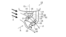
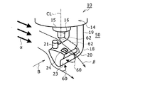
図1は、実施形態の内燃機関10において、点火プラグ14のうち、燃焼室50内に配置される部分を示す斜視図である。図2は、図1のA矢視図である。
FIG. 1 is a perspective view showing a portion of an
内燃機関10は、シリンダヘッド12(図2)と、シリンダ部材及びピストン(図示せず)とを備える。シリンダヘッド12は、シリンダ部材と組み合わされて内部に燃焼室50を形成する。ピストンは、シリンダ部材に形成されたシリンダ孔の内側において、軸方向に往復移動可能に配置される。
The
内燃機関10は、例えばガソリンエンジンである。このような内燃機関10では、吸気ポート(図示せず)から燃料と空気との混合気が燃焼室に導入され、圧縮され点火されて燃焼した後、排気ポート(図示せず)から燃焼ガスとして排出される。
The
内燃機関10は、混合気が燃焼室50に導入された場合に、燃焼室50内での混合気による吸気流がタンブル流と呼ばれる縦渦を形成するように構成される。そして、吸気工程の後、圧縮工程を経て点火時期に達した場合でも、燃焼室50には縦渦の成分が残存する。
The
一方、シリンダヘッド12の上部には、点火プラグ14が取り付けられる。点火プラグ14は、燃焼室50内に、シリンダヘッド12から下側に向いて突出するように配置される。
On the other hand, a
点火プラグ14は、外側の筒状に形成された金具ハウジング(図示せず)と、金具ハウジングの内側に保持された絶縁碍子15とを含み、絶縁碍子15の先端が、燃焼室50内に突き出している。そしてその突き出した絶縁碍子15の先端には中心電極16が設けられる。中心電極16の中心軸CLは、絶縁碍子15の中心軸と一致する。
The
点火プラグ14は、金具ハウジングの外周面に形成されたおねじ部(図示せず)によって、シリンダヘッド12にねじ結合で取り付けられる。
The
点火プラグ14は、金具ハウジングの下端部から燃焼室50内に延びた接地電極18を含む。点火プラグ14は、放電により中心電極16及び接地電極18の間で火花放電路を発生させるように構成され、混合気に点火するために用いられる。以下では、点火プラグ14が、燃焼室50の上壁面51(図2)の中央部付近に配置される場合を説明する。
The
接地電極18は、金具ハウジングから燃焼室50内に延出される延出部19と、延出部19の先端からL字形に屈曲して絶縁碍子15の先端(図1、図2の下端)と対面する側に伸びる腕部20とを含む。そして、腕部20の先端部の上側において、絶縁碍子15の先端と対面する部分には円柱状の第1突起部21が形成される。
The
接地電極18は、第1突起部21が中心電極16の先端に対し中心軸CLの方向に対面しないように、中心軸CLとは異なる位置に配置される。接地電極18の第1突起部21と中心電極16の先端との間には、放電時に火花放電路62が生じる放電ギャップが形成される。
The
上記のように、内燃機関10では点火時期において燃焼室50内に縦渦成分が残存するので、点火プラグ14の電極近傍には、縦渦の中心よりもやや上方に位置し、比較的流速の高い横向きの気流である高気流が生じている。内燃機関10の燃焼サイクルについて、気流のサイクル変動を平均化すると、点火プラグ14の中心電極16及び接地電極18は、吸気ポート側から排気ポート側に向かう高気流に曝される。図1、図2では、この高気流の流れ方向を矢印αで示している。
As described above, in the
そして、接地電極18の先端部である第1突起部21は、中心電極16の先端部が位置する中心電極16の中心軸CLより、点火プラグ14の周囲の気流の上流側(図1、図2の右側)に配置されている。これにより、電極周囲の気流によって、接地電極18の下流側で接地電極18近傍には、図1、図2に示すような後流渦60が形成される。
The
具体的には、接地電極18の先端部は、断面形状が略三角形に形成される。そして、中心電極16が接地電極の上側に配置され、かつ、中心電極16及び接地電極18の間を気流が左から右に流れるときに、接地電極18の上側の辺をほぼ水平か、または右下がりとしている。図1、図2では接地電極18の上側の辺が右下がりである場合を示している。また、このときに、接地電極18の下側の辺を右下がりとしている。これにより、接地電極18の腕部20の上側と下側とには、接地電極18の側面に沿う流れがそれぞれ発生し、接地電極18の後端では後流渦60が発生する。この後流渦60によって、後述するように接地電極18の気流下流側である背後に、安定して火炎を保持する保炎を行いやすくなる。
Specifically, the tip of the
また、図2に示すように、接地電極18の断面形状である略三角形において、右側の辺は、中間部に窪み22を有する形状である。言い換えれば図1に示すように、接地電極18の先端部において、気流の下流側に向く側面には、窪み22を含む溝部23が形成される。溝部23は、腕部20のほぼ全長にわたって形成される。窪み22により形成される溝部23は、後述するように接地電極18の先端部の下流側に後流渦60を発生させる効果を高くする。
In addition, as shown in FIG. 2, in the substantially triangular shape that is the cross-sectional shape of the
さらに、接地電極18の第1突起部21は、白金などの耐摩耗材料により形成される。これにより、放電時の接地電極18の摩耗が抑制される。また、接地電極18において、第1突起部21以外の部分は、第1突起部21より耐摩耗性の低い鉄系の材料により形成される。
Further, the
このような接地電極18の先端部は、渦発生部である。より詳しく説明すると、気流方向αにおいて、接地電極18の背後である中心電極16側には、放電ギャップGを流れた気流が入り込んで、後流渦60を形成する。このとき、接地電極18の腕部20の上側面において、気流の下流側端部が、腕部20の後側、すなわち気流の下流側において腕部20の近傍の気流を剥離させて、下流側に後流渦60を発生させる。
The tip of the
後流渦60は、電極の下流側で電極に沿う流れが剥離するような場合に、電極の下流側に生じる循環流れである。後流渦60の内部で混合気が着火されると、後述のように、火炎の一部が後流渦60の循環領域内に取り込まれて、高温の燃焼ガスを電極の下流側近傍に安定的に保持することができる。
The
そして、電極16,18間を流れる気流によって変形した火花放電路62または火炎、または火花放電路62及び火炎が腕部20の下流側の後流渦60内に進入する。具体的には、接地電極18及び中心電極16は、電極間、すなわち放電ギャップを通過する気流が、図1、図2に矢印βで示すように、燃焼室50の上壁面51から離れる側である斜め下方向に曲げられる。気流が電極間を通過しながら斜め下方向に曲げられることにより、その気流が後流渦60に巻き込まれやすくなっている。また、接地電極18の腕部20の下側面が気流の下流側に向かって上壁面51から離れる方向に上下方向に対し傾斜している。これにより、腕部20の下側を流れる気流を下向きに曲げて、それに伴って、上側で放電ギャップを通過する気流もより強く下側に曲げることができる。また、腕部20の下側を流れる気流によっても、腕部20の背後に後流渦60を発生させることができる。
Then, the
また、中心電極16及び接地電極18の間で発生した火花放電路62の付近に後流渦60があると、火花放電路62と、その火花放電路62の周囲に生じる初期火炎である初期火炎核(図3の破線γ)とが、後流渦60に巻き込まれて進入する。また、電極間を通過した気流が上記のように斜め下方向に曲げられると、火花放電路62及び初期火炎核も図1、図2に示すように気流に伴って斜め下方向に中間部が曲げられる。そして、火花放電路62及び初期火炎核が後流渦60に多く巻き込まれて進入して保持される。後述のように火花放電路62は、放電開始直後では、接地電極18の第1突起部21と中心電極16の先端面とを結ぶように形成されるが、気流に流されて、火花放電路62の一端が第1突起部21から腕部20の下流側端に移動する。図1、図2では、破線U1で放電開始直後の火花放電路62を示しており、破線U2で下流側への移動後の火花放電路62を示している。以下、火花放電路62は、火花62と記載する。
Further, if there is a
図3は、図2において、放電開始から火花62が後流渦60内に進入するまでの時間的変化を示す図である。図3(a)に示すように、放電開始直後では、火花62は、中心電極16の先端面の接地電極18側端(図3(a)の左端)と、接地電極18の第1突起部21の先端面における中心電極16側端(図3(a)の右端)とを最短経路で結ぶ略直線状となることがある。このことは、確率的に多く発生する。
FIG. 3 is a diagram showing a temporal change from the start of discharge until the
その後、図3(b)に示すように、火花62は気流によって下流側に中間部が流されて変形し下流側に伸長する。そして、気流によって火花62がさらに変形すると、火花62の一部が接地電極18の腕部20の上面における中心電極16側端に接近する。このとき、火花62は、電気抵抗値が小さい経路を選んで形成されるので、火花62の付け根である一端の位置が接地電極18の第1突起部21の先端から腕部20の上面の下流側端に移動する(図3(c))。
Thereafter, as shown in FIG. 3B, the
その後、図3(d)に示すように、気流によって、さらに火花62の中間部は下流側に曲げられるように変形して、接地電極18の腕部20の背後の後流渦60内に進入して巻き込まれる。このとき、火花62は、後流渦60の内部を通過する。
Thereafter, as shown in FIG. 3 (d), the intermediate portion of the
このような放電中において、火花62は周囲に熱を供給して混合気を着火する。着火して発生した初期火炎核も、火花62と同様に気流によって流されて変形する。図3(b)(c)(d)では、火花62を囲む破線γにより、初期火炎核を示している。
During such discharge, the
接地電極18の腕部20の背後に後流渦60が発生した場合において、その後流渦60の内部を通過する火花62によって生じた初期火炎核は、そのまま後流渦60の循環流の内部に取り込まれる。これにより、高温の燃焼ガスを、接地電極18の下流側直近部分に安定的に保持することができる。そして、その保持された燃焼ガスの熱により、気流によって流されてくる未燃ガスも継続的に着火させ、火炎を安定的に保持することができる。このような気流がある場での燃焼ガス及び火炎の安定的な保持は「保炎」と呼ばれる。火花62は、図2に砂地P部分で示す保炎領域の内部へ直接エネルギを供給でき、火炎の発達を促進する。これにより、火花62の放電終了後も点火プラグ14の周囲の未燃ガスを継続的に着火させることが可能になり、燃焼を促進できるとともに、燃焼を安定化することができる。この結果、安定な着火のための必要エネルギも、従来の点火方法に比べて低減できる。
When the
さらに、初期火炎核も火花62と同様に、気流によって流されるため、電極間を通過して斜め下方向に流れる気流によって、初期火炎核は接地電極18の腕部20の背後における後流渦60に巻き込まれる。これにより、後流渦60の上流側で着火した初期火炎核の一部によっても保炎を実現することができる。
Further, since the initial flame core is also flowed by the air current, like the
また、後述する図5、図6に示すように、接地電極18の第1突起部21の上端面の下流側端と中心電極16の下端面の上流側端とを結ぶ直線L1と、点火プラグ14の上流側における気流の向きαとのなす角度は、−30°〜+45°の範囲とすることが好ましい。
Further, as shown in FIG. 5 and FIG. 6 to be described later, a straight line L1 connecting the downstream end of the upper end surface of the
このとき、図5のように、接地電極18の上端から中心電極16の下端に向かう方向が、気流の流れ方向αより下向き、すなわち上壁面51より離れる側(例えば図5の斜め下側)である場合には、直線L1と気流の向きαとのなす角度が負であることを意味する。一方、図6のように、接地電極18の上端から中心電極16の下端に向かう方向が、気流の流れ方向αより上向き、すなわち上壁面51に近づく側(図6の斜め上側)である場合には、直線L1と気流の向きαとのなす角度が正であることを意味する。
At this time, as shown in FIG. 5, the direction from the upper end of the
上記の内燃機関10によれば、接地電極18の摩耗を抑制できるとともに、高気流が流れる条件の下でも着火性の向上及び燃焼の安定化を、低い点火エネルギで実現できる。そして、燃焼の安定化を図れるので、燃焼変動及びトルク変動を抑制できる。これにより、点火限界をより高気流で、より混合気が希薄となるリーンが生じる側に拡張できる。
According to the
図4は、実施形態の効果を確認するために行ったシミュレーション結果を示す図である。シミュレーションでは、図1、図2に示した実施形態と同様の構成を用いて行った。シミュレーションでは、株式会社CD−adapco製の汎用流体解析ソフト「STAR−CD」により、火花点火から混合気への着火にかけての現象を計算した。図4に示すシミュレーション結果から理解されるように、気流の流れ方向αについて、接地電極18の背後(図6の右側)で保炎が行われてその背後から連続して火炎64が広がっている。これにより、燃焼の安定化を図れることを確認できた。
FIG. 4 is a diagram illustrating a simulation result performed to confirm the effect of the embodiment. In the simulation, the same configuration as that of the embodiment shown in FIGS. 1 and 2 was used. In the simulation, a phenomenon from spark ignition to ignition of the air-fuel mixture was calculated using general-purpose fluid analysis software “STAR-CD” manufactured by CD-adapco. As understood from the simulation results shown in FIG. 4, flame holding is performed behind the ground electrode 18 (on the right side in FIG. 6) in the airflow direction α, and the
なお、図示は省略するが、従来技術の形状として、接地電極の腕部の形状が直方体状であり、上側に中心電極の中心軸の方向に対向するように突起部が形成される構成では、高気流条件下で火花が気流に流されることが考えられる。一方、この構成では、火花がある長さ以上に伸長すると火花が途中で途切れるので、点火プラグの電極間で再放電が生じる。これにより燃焼が不安定になる可能性がある。上記の実施形態ではこのような不都合が生じにくくなる。 In addition, although illustration is omitted, as a shape of the prior art, in the configuration in which the shape of the arm portion of the ground electrode is a rectangular parallelepiped shape, and the protrusion is formed on the upper side so as to face the direction of the central axis of the center electrode, It is conceivable that sparks are swept into the airflow under high airflow conditions. On the other hand, in this configuration, when the spark extends beyond a certain length, the spark is interrupted in the middle, and re-discharge occurs between the electrodes of the spark plug. This can lead to unstable combustion. In the above embodiment, such inconvenience is less likely to occur.
図5、図6は、実施形態の内燃機関10の別例の2例を示している図2に対応する図である。図5の例では、接地電極18の先端部である第1突起部21の上端が、中心電極16の先端部の下端よりも上方に配置される。また、直線L1と、直線L2に沿う点火プラグ14の前方の気流方向αとのなす角度が、−30°である。
FIGS. 5 and 6 are views corresponding to FIG. 2 showing two other examples of the
図5に示す構成では、接地電極18の第1突起部21の先端が絶縁碍子15の先端(図5の下端)に大きく接近するので、電極間を通過する気流は斜め下側に急激に曲げられる。このような構成では、点火プラグ14において、燃焼室50の内側に配置される部分の上下方向長さを小さくできる。
In the configuration shown in FIG. 5, the tip of the
一方、図6の例では、接地電極18の先端部である第1突起部21の上端が、中心電極16の先端部の下端よりも下方に配置される。また、直線L1と、直線L2に沿う点火プラグ14の前方の気流方向αとのなす角度が、+45°である。
On the other hand, in the example of FIG. 6, the upper end of the
図6に示す構成では、図6の左側から中心電極16に衝突するように流れる気流が矢印δで示すように斜め下側に曲げられるので、その下側で電極間を通過する気流も斜め下側に曲げられる。
In the configuration shown in FIG. 6, since the airflow flowing so as to collide with the
図7は、実施形態の内燃機関の別例を示している図1に対応する図である。図8は、図7のB矢視図である。 FIG. 7 is a view corresponding to FIG. 1 showing another example of the internal combustion engine of the embodiment. FIG. 8 is a view taken in the direction of arrow B in FIG.
図7、図8に示す構成では、図1、図2に示す構成において、接地電極18の腕部20の上側面における気流の下流側端部に、断面略直方体状の第2突起部24が形成される。これにより、第2突起部24は、第1突起部21よりも気流の下流側に形成される。第2突起部24は、腕部20の長手方向(図8の紙面の表裏方向)において、第1突起部21とほぼ同じ位置に形成される。第2突起部24も、第1突起部21と同様に、白金などの耐摩耗材料により形成される。さらに、第2突起部24の上端は、第1突起部21の上端より低い。
7 and 8, in the configuration shown in FIGS. 1 and 2, the
上記の構成によれば、第1突起部21と中心電極16との間で形成される火花62が気流によって流される際に、火花62が電気抵抗の低い経路に形成されるので、火花62の一端を第1突起部21から、下流側の第2突起部24へ移動させることができる。この第2突起部24は、耐摩耗材料により形成される。これにより、火花62が気流によって流される際に、火花62の一端が、第1突起部21及び第2突起部24より耐摩耗性の低い材料の腕部20の下流側端に移動することを抑制できる。このため、接地電極18の摩耗をさらに抑制できる。また、第2突起部24の上端が第1突起部21の上端より低いので、気流の流れが第2突起部24によって過度に邪魔されることがない。また、初期において、火花が第1突起部21より先に、第2突起部24と中心電極16との間で形成されることがない。その他の構成及び作用は、図1、図2の構成と同様である。
According to the above configuration, when the
図9は、実施形態の内燃機関の別例を示している図1に対応する図である。図10は、図9のC矢視図である。 FIG. 9 is a view corresponding to FIG. 1 showing another example of the internal combustion engine of the embodiment. 10 is a view taken in the direction of arrow C in FIG.
図9、図10に示す構成では、上記の図7、図8に示す構成において、接地電極18の腕部20の上側面における先端寄り部分に、腕部20の先端面(図9、図10の紙面の表側面)にほぼ平行な壁部26が突出して形成される。壁部26は、腕部20の周囲の気流についてのほぼ上流側端(図9、図10の左端)からほぼ下流側端(図9、図10の右端)にわたる部分に形成される。壁部26は、例えば腕部20の上側面に溶接により固定される。壁部26は第1突起部に相当する。このような構成では、壁部26が、図7、図8の構成の第1突起部21及び第2突起部24を合わせた機能を有する。壁部26は、白金などの耐摩耗材料により形成される。壁部26において、下流側端の上端は、上流側端の上端より低い。
In the configuration shown in FIGS. 9 and 10, in the configuration shown in FIGS. 7 and 8, the tip surface of the arm portion 20 (see FIGS. 9 and 10) The
上記の構成によれば、まず壁部26の上流側端部の上端と中心電極16との間で、U1で示す火花62が形成され、その後、火花62が気流によって流されて、U2で示すように火花62の一端が壁部26の上流側端部から下流側端部の上端に移動することが多い。これにより、火花62が気流によって流される場合でも、火花62の一端が耐摩耗性の低い材料の腕部20の下流側端に移動することを抑制できる。このため、接地電極18の摩耗を抑制できる。さらに、腕部20において上流側及び下流側の2つに分離した突起部を溶接で固定する場合に比べて、腕部20に壁部26を溶接で固定する際の溶接回数を少なくできる。その他の構成及び作用は、図7、図8の構成と同様である。
According to the above configuration, first, the
なお、上記の各例の構成において、接地電極18の断面が略三角形の先端部において、下流側の辺となる右側の辺は直線状として、中間部の窪みを有しない形状としてもよい。また、上記の各例の構成では、第1突起部21が円柱状である場合を説明したが、第1突起部を腕部20の長手方向(例えば図2の紙面の表裏方向)に長い壁状としてもよい。また、図7、図8の構成において、第2突起部も同様に壁状としてもよい。
In the configuration of each of the above examples, at the tip of the
10 内燃機関、12 シリンダヘッド、14 点火プラグ、15 絶縁碍子、16 中心電極、18 接地電極、19 延出部、20 腕部、21 第1突起部、22 窪み、23 溝部、24 第2突起部、26 壁部、50 燃焼室、51 上壁面、60 後流渦、62 火花放電路(火花)64 火炎。
DESCRIPTION OF
Claims (4)
前記点火プラグは中心電極及び接地電極を含み、放電により中心電極及び接地電極の間で火花放電路が発生するように構成され、
前記点火プラグは、
前記接地電極の近傍の気流を剥離させて下流側に後流渦を発生させる渦発生部を有し、
前記渦発生部は、断面形状が略三角形の前記接地電極により形成され、前記中心電極が前記接地電極の上側に配置され、かつ、前記中心電極及び前記接地電極の間を気流が左から右に流れるときに、前記接地電極の上側の辺をほぼ水平か、または右下がりとし、かつ、前記接地電極の下側の辺を右下がりとしており、
前記接地電極の上側で、かつ、前記中心電極の中心軸より気流の上流側に耐摩耗材料により形成された第1突起部を含む、内燃機関。 With a spark plug protruding into the combustion chamber,
The spark plug includes a center electrode and a ground electrode, and is configured such that a spark discharge path is generated between the center electrode and the ground electrode by discharge,
The spark plug is
Having a vortex generating part for separating the airflow in the vicinity of the ground electrode and generating a wake vortex on the downstream side;
The vortex generator is formed by the ground electrode having a substantially triangular cross-sectional shape, the center electrode is disposed above the ground electrode, and an air current flows from the left to the right between the center electrode and the ground electrode. When flowing, the upper side of the ground electrode is substantially horizontal or lower right, and the lower side of the ground electrode is lower right,
An internal combustion engine including a first protrusion formed of a wear-resistant material on the upper side of the ground electrode and upstream of the central axis of the center electrode.
前記中心電極が前記接地電極の上側に配置され、かつ、前記中心電極及び前記接地電極の間を気流が左から右に流れるときに、前記接地電極の右側の辺は直線状、または中間部に窪みを有する形状である、内燃機関。 The internal combustion engine according to claim 1,
When the center electrode is disposed on the upper side of the ground electrode and an airflow flows between the center electrode and the ground electrode from the left to the right, the right side of the ground electrode is linear or in the middle. An internal combustion engine having a shape with a depression.
前記接地電極の上端面の下流側端と前記中心電極の下端面の上流側端とを結ぶ直線と、前記点火プラグ上流側の気流の向きとのなす角度が、前記接地電極の上端から前記中心電極の下端に向かう方向が気流方向より下向きである場合を負とし、上向きである場合を正とした場合に、−30°〜+45°の範囲である、内燃機関。 The internal combustion engine according to claim 1 or 2,
The angle formed by the straight line connecting the downstream end of the upper end surface of the ground electrode and the upstream end of the lower end surface of the center electrode and the direction of the airflow upstream of the spark plug is from the upper end of the ground electrode to the center. An internal combustion engine having a range of −30 ° to + 45 ° when the direction toward the lower end of the electrode is negative with respect to the air flow direction and negative when the direction is upward.
前記接地電極の上側で、かつ前記第1突起部よりも気流の下流側に耐摩耗材料で形成された第2突起部を備え、
前記第2突起部の上端が前記第1突起部の上端より低い、内燃機関。 The internal combustion engine according to any one of claims 1 to 3,
A second protrusion formed of an abrasion-resistant material on the upper side of the ground electrode and on the downstream side of the airflow from the first protrusion;
An internal combustion engine, wherein an upper end of the second protrusion is lower than an upper end of the first protrusion.
Priority Applications (1)
| Application Number | Priority Date | Filing Date | Title |
|---|---|---|---|
| JP2016027248A JP6610323B2 (en) | 2016-02-16 | 2016-02-16 | Internal combustion engine |
Applications Claiming Priority (1)
| Application Number | Priority Date | Filing Date | Title |
|---|---|---|---|
| JP2016027248A JP6610323B2 (en) | 2016-02-16 | 2016-02-16 | Internal combustion engine |
Publications (2)
| Publication Number | Publication Date |
|---|---|
| JP2017147086A true JP2017147086A (en) | 2017-08-24 |
| JP6610323B2 JP6610323B2 (en) | 2019-11-27 |
Family
ID=59680893
Family Applications (1)
| Application Number | Title | Priority Date | Filing Date |
|---|---|---|---|
| JP2016027248A Active JP6610323B2 (en) | 2016-02-16 | 2016-02-16 | Internal combustion engine |
Country Status (1)
| Country | Link |
|---|---|
| JP (1) | JP6610323B2 (en) |
Cited By (5)
| Publication number | Priority date | Publication date | Assignee | Title |
|---|---|---|---|---|
| WO2019138801A1 (en) * | 2018-01-15 | 2019-07-18 | 株式会社デンソー | Spark plug |
| JP2019125570A (en) * | 2018-01-15 | 2019-07-25 | 株式会社デンソー | Spark plug |
| US10693280B2 (en) | 2018-10-09 | 2020-06-23 | Denso Corporation | Spark plug |
| US10886709B1 (en) | 2019-06-19 | 2021-01-05 | Denso Corporation | Spark plug that prevents gas turbulence in the discharge space |
| US10951012B2 (en) | 2018-01-12 | 2021-03-16 | Denso Corporation | Spark plug for internal combustion engines and internal combustion engine |
Citations (2)
| Publication number | Priority date | Publication date | Assignee | Title |
|---|---|---|---|---|
| JP2012150992A (en) * | 2011-01-19 | 2012-08-09 | Ngk Spark Plug Co Ltd | Spark plug mounting structure, and spark plug |
| JP2015124674A (en) * | 2013-12-26 | 2015-07-06 | トヨタ自動車株式会社 | Internal combustion engine |
-
2016
- 2016-02-16 JP JP2016027248A patent/JP6610323B2/en active Active
Patent Citations (2)
| Publication number | Priority date | Publication date | Assignee | Title |
|---|---|---|---|---|
| JP2012150992A (en) * | 2011-01-19 | 2012-08-09 | Ngk Spark Plug Co Ltd | Spark plug mounting structure, and spark plug |
| JP2015124674A (en) * | 2013-12-26 | 2015-07-06 | トヨタ自動車株式会社 | Internal combustion engine |
Cited By (7)
| Publication number | Priority date | Publication date | Assignee | Title |
|---|---|---|---|---|
| US10951012B2 (en) | 2018-01-12 | 2021-03-16 | Denso Corporation | Spark plug for internal combustion engines and internal combustion engine |
| WO2019138801A1 (en) * | 2018-01-15 | 2019-07-18 | 株式会社デンソー | Spark plug |
| JP2019125570A (en) * | 2018-01-15 | 2019-07-25 | 株式会社デンソー | Spark plug |
| US10931086B2 (en) | 2018-01-15 | 2021-02-23 | Denso Corporation | Spark plug including a ground electrode having slanted surfaces and a facing portion facing a distal end surface of a center electrode |
| JP7275530B2 (en) | 2018-01-15 | 2023-05-18 | 株式会社デンソー | Spark plug |
| US10693280B2 (en) | 2018-10-09 | 2020-06-23 | Denso Corporation | Spark plug |
| US10886709B1 (en) | 2019-06-19 | 2021-01-05 | Denso Corporation | Spark plug that prevents gas turbulence in the discharge space |
Also Published As
| Publication number | Publication date |
|---|---|
| JP6610323B2 (en) | 2019-11-27 |
Similar Documents
| Publication | Publication Date | Title |
|---|---|---|
| JP6610323B2 (en) | Internal combustion engine | |
| JP5451490B2 (en) | Spark plug and engine | |
| JP4762110B2 (en) | Spark plug for internal combustion engine | |
| JP4762109B2 (en) | Spark plug for internal combustion engine | |
| ES2777877T3 (en) | Pre-chamber spark plug | |
| US5799637A (en) | Rocket effect sparking plug | |
| CN105637216B (en) | Controlled spark ignition flame kernel flow | |
| JP2013503447A (en) | Prechamber spark plug | |
| US7741762B2 (en) | Dual-spark pre-chambered spark igniter | |
| JPWO2008102842A1 (en) | Spark plug and internal combustion engine provided with spark plug | |
| JP6731230B2 (en) | Spark plug for internal combustion engine and ignition device equipped with the same | |
| JP2014026754A (en) | Ignition device | |
| JP5321431B2 (en) | In-cylinder internal combustion engine | |
| JP4453024B2 (en) | In-cylinder internal combustion engine | |
| JP6390636B2 (en) | Internal combustion engine | |
| KR101359170B1 (en) | Spark Plug | |
| JP2017004882A (en) | Ignition plug | |
| JP2019218864A (en) | Spark ignition type internal combustion engine | |
| JP6645168B2 (en) | Spark plug | |
| JP6192582B2 (en) | Internal combustion engine and spark plug | |
| JP2022042067A (en) | Spark plug for internal combustion engine and internal combustion engine including the same | |
| JP6661243B2 (en) | Spark plug | |
| JP2020061261A (en) | Spark plug | |
| JP7018601B2 (en) | Spark plug | |
| JP7302462B2 (en) | Cylinder head structure of internal combustion engine |
Legal Events
| Date | Code | Title | Description |
|---|---|---|---|
| A621 | Written request for application examination |
Free format text: JAPANESE INTERMEDIATE CODE: A621 Effective date: 20181029 |
|
| A131 | Notification of reasons for refusal |
Free format text: JAPANESE INTERMEDIATE CODE: A131 Effective date: 20190716 |
|
| A977 | Report on retrieval |
Free format text: JAPANESE INTERMEDIATE CODE: A971007 Effective date: 20190712 |
|
| A521 | Request for written amendment filed |
Free format text: JAPANESE INTERMEDIATE CODE: A523 Effective date: 20190917 |
|
| TRDD | Decision of grant or rejection written | ||
| A01 | Written decision to grant a patent or to grant a registration (utility model) |
Free format text: JAPANESE INTERMEDIATE CODE: A01 Effective date: 20191001 |
|
| A61 | First payment of annual fees (during grant procedure) |
Free format text: JAPANESE INTERMEDIATE CODE: A61 Effective date: 20191014 |
|
| R150 | Certificate of patent or registration of utility model |
Ref document number: 6610323 Country of ref document: JP Free format text: JAPANESE INTERMEDIATE CODE: R150 |