JP2017146647A - Display device, input device, head-mounted type display device, control method for display device, and program - Google Patents

Display device, input device, head-mounted type display device, control method for display device, and program Download PDF

Info

Publication number
JP2017146647A
JP2017146647A JP2016025670A JP2016025670A JP2017146647A JP 2017146647 A JP2017146647 A JP 2017146647A JP 2016025670 A JP2016025670 A JP 2016025670A JP 2016025670 A JP2016025670 A JP 2016025670A JP 2017146647 A JP2017146647 A JP 2017146647A
Authority
JP
Japan
Prior art keywords
display
control unit
detected
image
unit
Prior art date
Legal status (The legal status is an assumption and is not a legal conclusion. Google has not performed a legal analysis and makes no representation as to the accuracy of the status listed.)
Granted
Application number
JP2016025670A
Other languages
Japanese (ja)
Other versions
JP6631299B2 (en
Inventor
和夫 西沢
Kazuo Nishizawa
和夫 西沢
Current Assignee (The listed assignees may be inaccurate. Google has not performed a legal analysis and makes no representation or warranty as to the accuracy of the list.)
Seiko Epson Corp
Original Assignee
Seiko Epson Corp
Priority date (The priority date is an assumption and is not a legal conclusion. Google has not performed a legal analysis and makes no representation as to the accuracy of the date listed.)
Filing date
Publication date
Application filed by Seiko Epson Corp filed Critical Seiko Epson Corp
Priority to JP2016025670A priority Critical patent/JP6631299B2/en
Publication of JP2017146647A publication Critical patent/JP2017146647A/en
Application granted granted Critical
Publication of JP6631299B2 publication Critical patent/JP6631299B2/en
Active legal-status Critical Current
Anticipated expiration legal-status Critical

Links

Images

Abstract

PROBLEM TO BE SOLVED: To easily increase variations of operation and to achieve improvement of operability in a configuration enabling touch operation with respect to an operation surface.SOLUTION: An HMD 100 comprising an image display section 20 having a display area displays a prescribed image by the image display section 20, detects an operation position in a track pad 14 receiving contact operation, moves a display position of the prescribed image according to the operation position detected in the track pad 14, and changes association between the operation position and the display position of the prescribed image when detecting one operation position in the track pad 14 and when detecting a plurality of operation positions in the track pad 14.SELECTED DRAWING: Figure 1

Description

本発明は、表示装置、入力装置、頭部装着型表示装置、表示装置の制御方法、及び、プログラムに関する。   The present invention relates to a display device, an input device, a head-mounted display device, a display device control method, and a program.

従来、タッチ操作を受け付ける装置が知られている(例えば、特許文献1参照)。特許文献1記載の情報処理装置は、操作者の指やタッチペン等による入力を受け付ける接触指手段を備え、ジェスチャ情報を入力可能な構成である。この情報処理装置は、ジェスチャを読み取ってコマンドを発生し、このコマンドに対応する動作を実行できる。例えば、情報処理装置は、接触指手段に接触する指の数に応じて、電源をONする動作と、電源をOFFする動作とを実行できる。   Conventionally, a device that receives a touch operation is known (for example, see Patent Document 1). The information processing apparatus described in Patent Literature 1 includes a contact finger unit that receives input from an operator's finger, a touch pen, or the like, and is configured to be able to input gesture information. The information processing apparatus can generate a command by reading a gesture and execute an operation corresponding to the command. For example, the information processing apparatus can execute an operation of turning on the power and an operation of turning off the power in accordance with the number of fingers touching the contact finger means.

特開平9−231004号公報Japanese Patent Laid-Open No. 9-23004

特許文献1記載の装置のように、タッチ操作を利用することによって、各種装置を指等により容易に操作できるという利点がある。その一方で、操作の種類を増やすためには、指の動きが複雑化する傾向があった。
本発明は上記事情に鑑みてなされたものであり、操作面に対するタッチ操作が可能な構成において、簡単に操作のバリエーションを増やし、操作性の向上を図ることを目的とする。
There is an advantage that various devices can be easily operated with a finger or the like by using a touch operation like the device described in Patent Document 1. On the other hand, in order to increase the types of operations, there has been a tendency for finger movements to become complicated.
The present invention has been made in view of the above circumstances, and an object thereof is to easily increase operation variations and improve operability in a configuration in which a touch operation on an operation surface is possible.

上記目的を達成するために、本発明の表示装置は、接触操作を受け付ける操作面と、画像を表示する表示領域を有する表示部と、前記操作面における操作位置を検出し、検出した操作に応じて前記表示部の表示を制御する制御部と、を備え、前記制御部は、前記表示部により所定画像を表示し、前記所定画像の表示位置を前記操作面の操作位置に応じて移動させ、前記操作面で1つの操作位置を検出した場合と、複数の操作位置を検出した場合とで、前記操作位置と前記所定画像の表示位置との対応付けを変更すること、を特徴とする。
本発明によれば、操作面に対して接触操作を行う操作位置の数によって、操作に対応する所定画像の表示位置の移動の態様が変化する。このため、操作位置の数を変化させることで操作のバリエーションを増やすことができ、操作性の向上を図ることができる。
In order to achieve the above object, a display device of the present invention detects an operation surface that accepts a contact operation, a display unit that has a display area for displaying an image, and an operation position on the operation surface, and responds to the detected operation. A control unit that controls display of the display unit, and the control unit displays a predetermined image by the display unit, and moves a display position of the predetermined image according to an operation position of the operation surface, The association between the operation position and the display position of the predetermined image is changed between when one operation position is detected on the operation surface and when a plurality of operation positions are detected.
According to the present invention, the manner of movement of the display position of the predetermined image corresponding to the operation changes depending on the number of operation positions where the contact operation is performed on the operation surface. For this reason, the variation of operation can be increased by changing the number of operation positions, and operativity can be improved.

また、本発明は、上記表示装置において、前記制御部は、前記所定画像の表示位置を前記操作面の操作位置に応じて移動させる際に前記操作面で2つの操作位置を検出した場合、検出した2つの操作位置とは異なる操作位置に対応する表示位置に、前記所定画像の表示位置を移動させること、を特徴とする。
本発明によれば、2つの操作位置で接触操作を行うことにより、所定画像の表示位置を移動させる操作のバリエーションを増やすことができ、操作性の向上を図ることができる。
In the display device according to the aspect of the invention, when the control unit detects two operation positions on the operation surface when moving the display position of the predetermined image according to the operation position on the operation surface, the detection is performed. The display position of the predetermined image is moved to a display position corresponding to an operation position different from the two operation positions.
According to the present invention, by performing the contact operation at the two operation positions, it is possible to increase the variation of the operation for moving the display position of the predetermined image, and it is possible to improve the operability.

また、本発明は、上記表示装置において、前記制御部は、前記操作面で検出した2つの操作位置に基づいて、検出した2つの操作位置とは異なる操作位置に対応する表示位置に前記所定画像の表示位置を移動させた後、前記操作面で新たに1つの操作位置を検出した場合に、当該新たな1つの操作位置に対応する表示位置に前記所定画像の表示位置を移動させること、を特徴とする。
本発明によれば、2つの操作位置に加えて新たな位置で操作が行われた場合に、この新たな操作位置に対応して所定画像の表示位置を制御できる。これにより、所定画像の表示位置を移動させる操作のバリエーションを増やすことができ、操作性の向上を図ることができる。
According to the present invention, in the display device, the control unit is configured to display the predetermined image at a display position corresponding to an operation position different from the two detected operation positions based on the two operation positions detected on the operation surface. Moving one display position to the display position corresponding to the one new operation position when one new operation position is detected on the operation surface. Features.
According to the present invention, when an operation is performed at a new position in addition to the two operation positions, the display position of the predetermined image can be controlled corresponding to the new operation position. Thereby, the variation of operation which moves the display position of a predetermined image can be increased, and operability can be improved.

また、本発明は、上記表示装置において、前記制御部は、前記操作面で検出した1つの操作位置に基づいて前記所定画像を表示した後に、前記操作面で2つの操作位置の操作を検出した場合、前記所定画像の表示を停止させること、を特徴とする。
本発明によれば、所定画像の表示状態を変更することにより、検出される操作位置の数が変化したことを使用者に通知できる。
According to the present invention, in the display device, the control unit detects an operation at two operation positions on the operation surface after displaying the predetermined image based on one operation position detected on the operation surface. In the case, the display of the predetermined image is stopped.
According to the present invention, it is possible to notify the user that the number of detected operation positions has changed by changing the display state of the predetermined image.

また、本発明は、上記表示装置において、前記制御部は、前記所定画像の表示位置を前記操作面の操作位置に応じて移動させる移動表示を実行し、移動表示の態様を、前記操作面で検出する操作位置の数に応じて切り替えること、を特徴とする。
本発明によれば、所定画像の移動表示の態様を切り替えることで、より一層の操作性の向上を図ることができる。
Further, according to the present invention, in the display device, the control unit executes a movement display that moves a display position of the predetermined image in accordance with an operation position of the operation surface, and sets the movement display mode on the operation surface. Switching is performed according to the number of operation positions to be detected.
According to the present invention, the operability can be further improved by switching the moving display mode of the predetermined image.

また、本発明は、上記表示装置において、前記制御部は、前記操作面で検出する操作位置の数に応じて前記所定画像の表示態様を切り替えること、を特徴とする。
本発明によれば、所定画像の表示態様を変更することにより、操作に適した所定画像の視認性を確保し、操作性のより一層の向上を図ることができる。
Further, the present invention is characterized in that, in the display device, the control unit switches a display mode of the predetermined image according to the number of operation positions detected on the operation surface.
According to the present invention, by changing the display mode of a predetermined image, the visibility of the predetermined image suitable for the operation can be ensured, and the operability can be further improved.

また、上記目的を達成するために、本発明の表示装置は、接触操作を受け付ける操作面と、画像を表示する表示領域を有する表示部と、前記操作面における操作位置を検出し、検出した操作位置に基づき表示制御用の位置を出力し、この表示制御用の位置に基づき画像を前記表示部に表示させる制御部と、を備え、前記制御部は、1つの操作位置を検出した場合と、複数の操作位置を検出した場合とで、検出した操作位置と前記表示制御用の位置との対応付けを変更すること、を特徴とする。
本発明によれば、操作面に対して接触操作を行う操作位置の数によって、操作に対応する所定画像の表示位置の制御の態様が変化する。このため、操作位置の数を変化させることで操作のバリエーションを増やすことができ、操作性の向上を図ることができる。
In order to achieve the above object, the display device of the present invention detects an operation surface that receives a touch operation, a display unit that has a display area for displaying an image, and an operation position on the operation surface, and detects the operation. A control unit that outputs a position for display control based on the position and displays an image on the display unit based on the position for display control, and the control unit detects one operation position; When a plurality of operation positions are detected, the association between the detected operation position and the display control position is changed.
According to the present invention, the manner of controlling the display position of the predetermined image corresponding to the operation changes depending on the number of operation positions where the touch operation is performed on the operation surface. For this reason, the variation of operation can be increased by changing the number of operation positions, and operativity can be improved.

また、本発明は、上記表示装置において、前記制御部は、前記操作面で複数の操作位置を検出した場合に、検出した複数の操作位置とは異なる操作位置に対応する前記表示制御用の位置を出力すること、を特徴とする。
本発明によれば、複数の操作位置で接触操作を行うことにより、所定画像の表示位置を移動させる操作のバリエーションを増やすことができ、操作性の向上を図ることができる。
In the display device according to the aspect of the invention, when the control unit detects a plurality of operation positions on the operation surface, the display control position corresponds to an operation position different from the detected operation positions. Is output.
According to the present invention, by performing the contact operation at a plurality of operation positions, it is possible to increase the variation of the operation for moving the display position of the predetermined image, and it is possible to improve the operability.

また、本発明は、上記表示装置において、前記制御部は、前記操作面で検出した複数の操作位置から仮想の操作位置を求め、前記仮想の操作位置に対応する前記表示制御用の位置を出力すること、を特徴とする。
本発明によれば、複数の操作位置における接触操作に対応して、表示位置を適切に移動させることができる。
In the display device according to the aspect of the invention, the control unit obtains a virtual operation position from a plurality of operation positions detected on the operation surface, and outputs the display control position corresponding to the virtual operation position. It is characterized by doing.
According to the present invention, it is possible to appropriately move the display position in response to contact operations at a plurality of operation positions.

また、本発明は、上記表示装置において、前記制御部は、前記操作面で検出した2つの操作位置に基づいて、検出した2つの操作位置とは異なる操作位置に対応する前記表示制御用の位置を出力し、その後、前記操作面で新たに1つの操作位置を検出した場合に、当該新たな1つの操作位置に対応する前記表示制御用の位置を出力すること、を特徴とする。
本発明によれば、複数の操作位置の接触操作に対応して、所定画像の表示位置を移動させる操作のバリエーションを増やすことができる。
According to the present invention, in the display device, the control unit is configured to display the display control position corresponding to an operation position different from the two detected operation positions based on the two operation positions detected on the operation surface. After that, when one new operation position is detected on the operation surface, the display control position corresponding to the one new operation position is output.
According to the present invention, it is possible to increase variations of operations for moving the display position of a predetermined image in response to contact operations at a plurality of operation positions.

また、本発明は、上記表示装置において、前記制御部は、前記表示制御用の位置を、出力済みの表示位置からの移動方向と移動量との少なくともいずれかにより指定する情報を出力すること、を特徴とする。
本発明によれば、表示領域と操作面とのサイズや形状を厳密に対応付ける必要がなく、多様な形状の操作面に対して適用できる。
In the display device according to the present invention, the control unit outputs information specifying the display control position by at least one of a movement direction and a movement amount from the output display position. It is characterized by.
According to the present invention, it is not necessary to strictly associate the sizes and shapes of the display area and the operation surface, and the present invention can be applied to operation surfaces having various shapes.

また、本発明は、上記表示装置において、前記表示部は、使用者の頭部に装着され、前記制御部は、前記表示部とは別体として構成される前記操作面における操作位置を検出すること、を特徴とする。
本発明によれば、頭部に表示装置を装着する使用者が操作面に対する操作を行う場合に、操作位置の数によって、所定画像の表示位置の移動の態様を変化させることができる。このため、操作位置の数を変化させることで操作のバリエーションを増やすことができ、操作性の向上を図ることができる。例えば、操作面を視認しにくい状態であっても、表示位置の移動状態を任意に操作できる。
In the display device according to the aspect of the invention, the display unit is mounted on a user's head, and the control unit detects an operation position on the operation surface configured separately from the display unit. It is characterized by this.
According to the present invention, when the user who wears the display device on the head performs an operation on the operation surface, the mode of movement of the display position of the predetermined image can be changed depending on the number of operation positions. For this reason, the variation of operation can be increased by changing the number of operation positions, and operativity can be improved. For example, even when it is difficult to visually recognize the operation surface, the moving state of the display position can be arbitrarily operated.

また、上記目的を達成するために、本発明の入力装置は、操作面に対する接触操作を受け付けて、前記操作面における操作位置を検出し、検出した操作位置に基づき、前記操作位置に対応する処理位置の情報を生成する操作情報生成部を備え、前記操作情報生成部は、前記操作面で1つの操作位置を検出した場合と、複数の操作位置を検出した場合とで、前記操作位置と前記処理位置との対応付けを変更すること、を特徴とする。
本発明によれば、操作面に対して接触操作を行う操作位置の数によって、操作に対応して実行する処理の内容を変化させることができる。このため、操作位置の数を変化させることで操作のバリエーションを増やすことができ、操作性の向上を図ることができる。
In order to achieve the above object, the input device of the present invention receives a contact operation on the operation surface, detects an operation position on the operation surface, and performs processing corresponding to the operation position based on the detected operation position. An operation information generation unit configured to generate position information, wherein the operation information generation unit detects the operation position and the operation position when detecting one operation position on the operation surface and when detecting a plurality of operation positions. The association with the processing position is changed.
According to the present invention, it is possible to change the contents of processing to be executed in response to an operation, depending on the number of operation positions where a contact operation is performed on the operation surface. For this reason, the variation of operation can be increased by changing the number of operation positions, and operativity can be improved.

また、上記目的を達成するために、本発明は、外光を透過する表示部を備える頭部装着型表示装置であって、接触操作を受け付ける操作面と、前記操作面における操作位置を検出し、検出した操作に応じて前記表示部の表示を制御する制御部と、を備え、前記制御部は、前記表示部により所定画像を表示し、前記所定画像の表示位置を前記操作面の操作位置に応じて移動させ、前記操作面で検出する操作位置に応じて、前記所定画像に対する前記外光の透過率を制御すること、を特徴とする。
本発明によれば、操作面に対して接触操作を行う操作位置に対応して画像を表示し、この画像の透過率を変化させることができる。このため、頭部装着型表示装置が表示する画像の外光に対する見え方を、操作に対応して変化させることができ、操作性の向上を図ることができる。
In order to achieve the above object, the present invention provides a head-mounted display device including a display unit that transmits external light, and detects an operation surface that receives a contact operation and an operation position on the operation surface. A control unit that controls display of the display unit according to the detected operation, and the control unit displays a predetermined image on the display unit, and the display position of the predetermined image is set to the operation position of the operation surface. And the transmittance of the external light with respect to the predetermined image is controlled in accordance with the operation position detected on the operation surface.
According to the present invention, it is possible to display an image corresponding to an operation position where a contact operation is performed on the operation surface, and to change the transmittance of the image. For this reason, the appearance of the image displayed by the head-mounted display device with respect to the external light can be changed corresponding to the operation, and the operability can be improved.

また、本発明は、上記表示装置において、前記制御部は、前記操作面で検出する操作位置に対応して前記所定画像の表示態様を変更すること、を特徴とする。
本発明によれば、外光に対する表示画像の見え方に加え、表示する画像の形状等の表示態様を変化させることができ、操作性のより一層の向上を図ることができる。
Further, the present invention is characterized in that, in the display device, the control unit changes a display mode of the predetermined image corresponding to an operation position detected on the operation surface.
According to the present invention, it is possible to change the display mode such as the shape of an image to be displayed in addition to the appearance of the display image with respect to external light, and further improve the operability.

また、上記目的を達成するために、本発明の表示装置の制御方法は、画像を表示する表示領域を有する表示部を備える表示装置を制御して、前記表示部により所定画像を表示し、接触操作を受け付ける操作面における操作位置を検出し、前記所定画像の表示位置を、前記操作面で検出される操作位置に応じて移動させ、前記操作面で1つの操作位置を検出した場合と、前記操作面における複数の操作位置を検出した場合とで、前記操作位置と前記所定画像の表示位置との対応付けを変更すること、を特徴とする。
本発明によれば、操作面に対して接触操作を行う操作位置の数によって、操作に対応する所定画像の表示位置の移動の態様が変化する。このため、操作位置の数を変化させることで操作のバリエーションを増やすことができ、操作性の向上を図ることができる。
In order to achieve the above object, the display device control method of the present invention controls a display device including a display unit having a display area for displaying an image, displays a predetermined image on the display unit, and performs contact. Detecting an operation position on an operation surface that receives an operation, moving a display position of the predetermined image according to an operation position detected on the operation surface, and detecting one operation position on the operation surface; The association between the operation position and the display position of the predetermined image is changed when a plurality of operation positions on the operation surface are detected.
According to the present invention, the manner of movement of the display position of the predetermined image corresponding to the operation changes depending on the number of operation positions where the contact operation is performed on the operation surface. For this reason, the variation of operation can be increased by changing the number of operation positions, and operativity can be improved.

また、上記目的を達成するために、本発明は、画像を表示する表示領域を有する表示部を備える表示装置を制御するコンピューターが実行可能なプログラムであって、前記表示部により所定画像を表示し、接触操作を受け付ける操作面における操作位置を検出し、前記所定画像の表示位置を、前記操作面で検出される操作位置に応じて移動させ、前記操作面で1つの操作位置を検出した場合と、前記操作面における複数の操作位置を検出した場合とで、前記操作位置と前記所定画像の表示位置との対応付けを変更するためのプログラムである。
本発明によれば、操作面に対して接触操作を行う操作位置の数によって、操作に対応する所定画像の表示位置の移動の態様が変化する。このため、操作位置の数を変化させることで操作のバリエーションを増やすことができ、操作性の向上を図ることができる。
In order to achieve the above object, the present invention is a program executable by a computer that controls a display device including a display unit having a display area for displaying an image, and displays a predetermined image on the display unit. Detecting the operation position on the operation surface that accepts the contact operation, moving the display position of the predetermined image according to the operation position detected on the operation surface, and detecting one operation position on the operation surface; The program for changing the association between the operation position and the display position of the predetermined image when a plurality of operation positions on the operation surface are detected.
According to the present invention, the manner of movement of the display position of the predetermined image corresponding to the operation changes depending on the number of operation positions where the contact operation is performed on the operation surface. For this reason, the variation of operation can be increased by changing the number of operation positions, and operativity can be improved.

本発明は、上述した表示装置、表示装置の制御方法、及びプログラム以外の種々の形態で実現することも可能である。例えば、上記のプログラムを記録した記録媒体、プログラムを配信するサーバー装置、上記プログラムを伝送する伝送媒体、上記プログラムを搬送波内に具現化したデータ信号等の形態で実現できる。   The present invention can also be realized in various forms other than the above-described display device, display device control method, and program. For example, the present invention can be realized in the form of a recording medium that records the program, a server device that distributes the program, a transmission medium that transmits the program, a data signal that embodies the program in a carrier wave, and the like.

HMDの外観構成を示す説明図。Explanatory drawing which shows the external appearance structure of HMD. 画像表示部の光学系の構成を示す図。The figure which shows the structure of the optical system of an image display part. 画像表示部と撮像範囲の対応を示す説明図。Explanatory drawing which shows a response | compatibility with an image display part and an imaging range. HMDを構成する各部のブロック図。The block diagram of each part which comprises HMD. 制御部および記憶部のブロック図。The block diagram of a control part and a memory | storage part. HMDの動作を示すフローチャート。The flowchart which shows operation | movement of HMD. HMDの動作を示すフローチャート。The flowchart which shows operation | movement of HMD. HMDの操作に対応する表示の変化を示す説明図。Explanatory drawing which shows the change of the display corresponding to operation of HMD. HMDの操作に対応する表示の変化を示す説明図。Explanatory drawing which shows the change of the display corresponding to operation of HMD. HMDの操作に対応する表示の変化を示す説明図。Explanatory drawing which shows the change of the display corresponding to operation of HMD. HMDの操作に対応する表示の変化を示す説明図。Explanatory drawing which shows the change of the display corresponding to operation of HMD. HMDの操作に対応する表示の変化を示す説明図。Explanatory drawing which shows the change of the display corresponding to operation of HMD. HMDの操作に対応する表示の変化を示す説明図。Explanatory drawing which shows the change of the display corresponding to operation of HMD. HMDの操作に対応する表示の変化を示す説明図。Explanatory drawing which shows the change of the display corresponding to operation of HMD.

図1は、本発明を適用した実施形態に係るHMD(Head Mounted Display:頭部装着型表示装置)100の外観構成を示す説明図である。
HMD100は、使用者の頭部に装着された状態で使用者に虚像を視認させる画像表示部20(表示部)と、画像表示部20を制御する制御装置10と、を備える表示装置である。また、制御装置10(入力装置)は、使用者の操作を受け付ける各種のボタン、スイッチやトラックパッド14(操作面)を備え、使用者がHMD100を操作するコントローラーとして機能する。
FIG. 1 is an explanatory diagram showing an external configuration of an HMD (Head Mounted Display) 100 according to an embodiment to which the present invention is applied.
The HMD 100 is a display device that includes an image display unit 20 (display unit) that allows a user to visually recognize a virtual image while being mounted on the user's head, and a control device 10 that controls the image display unit 20. In addition, the control device 10 (input device) includes various buttons, switches, and track pads 14 (operation surface) that accept user operations, and functions as a controller for the user to operate the HMD 100.

画像表示部20は、使用者の頭部に装着される装着体であり、本実施形態では眼鏡形状を有する。画像表示部20は、右保持部21と、左保持部23と、前部フレーム27とを有する本体に、右表示ユニット22、左表示ユニット24、右導光板26、及び左導光板28を備える。
右保持部21及び左保持部23は、それぞれ、前部フレーム27の両端部から後方に延び、眼鏡のテンプル(つる)のように、使用者の頭部に画像表示部20を保持する。ここで、前部フレーム27の両端部のうち、画像表示部20の装着状態において使用者の右側に位置する端部を端部ERとし、使用者の左側に位置する端部を端部ELとする。右保持部21は、前部フレーム27の端部ERから、画像表示部20装着状態において使用者の右側頭部に対応する位置まで延伸して設けられる。左保持部23は、端部ELから、画像表示部20の装着状態において使用者の左側頭部に対応する位置まで延伸して設けられる。
The image display unit 20 is a wearing body that is worn on the user's head, and has a glasses shape in the present embodiment. The image display unit 20 includes a right display unit 22, a left display unit 24, a right light guide plate 26, and a left light guide plate 28 in a main body having a right holding unit 21, a left holding unit 23, and a front frame 27. .
Each of the right holding unit 21 and the left holding unit 23 extends rearward from both ends of the front frame 27, and holds the image display unit 20 on the user's head like a temple of glasses. Here, of both ends of the front frame 27, an end located on the right side of the user in the mounted state of the image display unit 20 is defined as an end ER, and an end located on the left side of the user is defined as an end EL. To do. The right holding unit 21 extends from the end ER of the front frame 27 to a position corresponding to the right side of the user when the image display unit 20 is mounted. The left holding unit 23 is provided to extend from the end EL to a position corresponding to the left side of the user when the image display unit 20 is mounted.

右導光板26及び左導光板28は、前部フレーム27に設けられる。右導光板26は、画像表示部20の装着状態において使用者の右眼の眼前に位置し、右眼に画像を視認させる。左導光板28は、画像表示部20の装着状態において使用者の左眼の眼前に位置し、左眼に画像を視認させる。   The right light guide plate 26 and the left light guide plate 28 are provided on the front frame 27. The right light guide plate 26 is positioned in front of the right eye of the user when the image display unit 20 is mounted, and causes the right eye to visually recognize the image. The left light guide plate 28 is positioned in front of the left eye of the user when the image display unit 20 is mounted, and causes the left eye to visually recognize the image.

前部フレーム27は、右導光板26の一端と左導光板28の一端とを互いに連結した形状を有し、この連結位置は、使用者が画像表示部20を装着する装着状態で、使用者の眉間に対応する。前部フレーム27は、右導光板26と左導光板28との連結位置において、画像表示部20の装着状態で使用者の鼻に当接する鼻当て部を設けてもよい。この場合、鼻当て部と右保持部21及び左保持部23とにより画像表示部20を使用者の頭部に保持できる。また、右保持部21及び左保持部23に、画像表示部20の装着状態において使用者の後頭部に接するベルト(図示略)を連結してもよく、この場合、ベルトによって画像表示部20を使用者の頭部に保持できる。   The front frame 27 has a shape in which one end of the right light guide plate 26 and one end of the left light guide plate 28 are connected to each other, and this connection position is in a wearing state in which the user wears the image display unit 20. Corresponding to the eyebrows. The front frame 27 may be provided with a nose pad portion that comes into contact with the user's nose when the image display unit 20 is mounted at a connection position between the right light guide plate 26 and the left light guide plate 28. In this case, the image display unit 20 can be held on the user's head by the nose pad, the right holding unit 21 and the left holding unit 23. Further, a belt (not shown) that contacts the back of the user when the image display unit 20 is mounted may be connected to the right holding unit 21 and the left holding unit 23. In this case, the image display unit 20 is used by the belt. Can be held on the person's head.

右表示ユニット22は、右導光板26による画像の表示に係るユニットであり、右保持部21に設けられ、装着状態において使用者の右側頭部の近傍に位置する。左表示ユニット24は、左導光板28による画像の表示に係るユニットであり、左保持部23に設けられ、装着状態において使用者の左側頭部の近傍に位置する。なお、右表示ユニット22及び左表示ユニット24を総称して単に「表示駆動部」とも呼ぶ。   The right display unit 22 is a unit related to display of an image by the right light guide plate 26 and is provided in the right holding unit 21 and is located in the vicinity of the right side of the user in the mounted state. The left display unit 24 is a unit related to display of an image by the left light guide plate 28 and is provided in the left holding unit 23 and is located in the vicinity of the left head of the user in the mounted state. The right display unit 22 and the left display unit 24 are also collectively referred to simply as a “display driving unit”.

本実施形態の右導光板26及び左導光板28は、光透過性の樹脂等によって形成される光学部であり、例えばプリズムであり、右表示ユニット22及び左表示ユニット24が出力する画像光を、使用者の眼に導く。
また、右導光板26及び左導光板28の表面に、調光板(図示略)を設けてもよい。調光板は、光の波長域により透過率が異なる薄板上の光学素子であり、いわゆる波長フィルターとして機能する。調光板は、例えば、使用者の眼の側とは反対の側である前部フレーム27の表側を覆うように配置される。この調光板の光学特性を適宜選択することにより、可視光、赤外光及び紫外光等の任意の波長域の光の透過率を調整することができ、外部から右導光板26及び左導光板28に入射し、右導光板26及び左導光板28を透過する外光の光量を調整できる。
The right light guide plate 26 and the left light guide plate 28 of the present embodiment are optical units formed of a light-transmitting resin or the like, and are, for example, prisms, and output image light output from the right display unit 22 and the left display unit 24. Lead to the eyes of the user.
A light control plate (not shown) may be provided on the surfaces of the right light guide plate 26 and the left light guide plate 28. The light control plate is an optical element on a thin plate having different transmittance depending on the wavelength region of light, and functions as a so-called wavelength filter. The light control board is arrange | positioned so that the front side of the front frame 27 which is the opposite side to the user's eyes side may be covered, for example. By appropriately selecting the optical characteristics of the light control plate, the transmittance of light in an arbitrary wavelength region such as visible light, infrared light, and ultraviolet light can be adjusted. The amount of external light incident on the light plate 28 and transmitted through the right light guide plate 26 and the left light guide plate 28 can be adjusted.

画像表示部20は、右表示ユニット22及び左表示ユニット24がそれぞれ生成する画像光を、右導光板26及び左導光板28に導き、この画像光によって虚像を使用者に視認させることによって、画像を表示する。使用者の前方から、右導光板26及び左導光板28を透過して外光が使用者の眼に入射する場合、使用者の眼には、虚像を構成する画像光および外光が入射することとなり、虚像の視認性が外光の強さに影響される。このため、例えば前部フレーム27に調光板を装着し、調光板の光学特性を適宜選択あるいは調整することによって、虚像の視認のしやすさを調整できる。典型的な例では、HMD100を装着した使用者が少なくとも外の景色を視認できる程度の光透過性を有する調光板を用いることができる。また、調光板を用いると、右導光板26及び左導光板28を保護し、右導光板26及び左導光板28の損傷や汚れの付着等を抑制する効果が期待できる。調光板は、前部フレーム27、或いは、右導光板26及び左導光板28のそれぞれに対し着脱可能としてもよく、複数種類の調光板を交換して装着可能としてもよく、調光板を省略してもよい。   The image display unit 20 guides the image light generated by the right display unit 22 and the left display unit 24 to the right light guide plate 26 and the left light guide plate 28, respectively, and makes the user visually recognize the virtual image by using the image light, thereby Is displayed. When the external light enters the user's eyes through the right light guide plate 26 and the left light guide plate 28 from the front of the user, the image light and the external light constituting the virtual image enter the user's eyes. In other words, the visibility of the virtual image is affected by the intensity of external light. For this reason, for example, by attaching a light control plate to the front frame 27 and appropriately selecting or adjusting the optical characteristics of the light control plate, the visibility of the virtual image can be adjusted. In a typical example, it is possible to use a light control plate having a light transmittance that allows a user wearing the HMD 100 to visually recognize at least the outside scenery. In addition, when the dimming plate is used, it is possible to protect the right light guide plate 26 and the left light guide plate 28 and to suppress the damage to the right light guide plate 26 and the left light guide plate 28, the adhesion of dirt, and the like. The light control plate may be detachable with respect to the front frame 27 or each of the right light guide plate 26 and the left light guide plate 28, or may be mounted by replacing a plurality of types of light control plates. May be omitted.

カメラ61は、画像表示部20の前部フレーム27に配設される。カメラ61は、使用者が画像表示部20を装着した状態で視認する外景方向を撮像することが望ましく、前部フレーム27の前面において、右導光板26及び左導光板28を透過する外光を遮らない位置に設けられる。図1の例では、カメラ61が前部フレーム27の端部ER側に配置される。カメラ61は、端部EL側に配置されてもよく、右導光板26と左導光板28との連結部に配置されてもよい。   The camera 61 is disposed on the front frame 27 of the image display unit 20. The camera 61 desirably captures an outside scene direction viewed by the user wearing the image display unit 20, and external light transmitted through the right light guide plate 26 and the left light guide plate 28 on the front surface of the front frame 27. It is provided at a position that does not block. In the example of FIG. 1, the camera 61 is disposed on the end ER side of the front frame 27. The camera 61 may be disposed on the end EL side, or may be disposed at a connection portion between the right light guide plate 26 and the left light guide plate 28.

カメラ61は、CCDやCMOS等の撮像素子及び撮像レンズ等を備えるデジタルカメラであり、本実施形態のカメラ61は単眼カメラであるが、ステレオカメラで構成してもよい。カメラ61は、HMD100の表側方向、換言すれば、HMD100を装着した状態における使用者の視界方向の少なくとも一部の外景(実空間)を撮像する。別の表現では、カメラ61は、使用者の視界と重なる範囲または方向を撮像し、使用者が注視する方向を撮像するということもできる。カメラ61の画角の広さは適宜設定可能であるが、本実施形態では、後述するように、使用者が右導光板26及び左導光板28を通して視認する外界を含む。より好ましくは、右導光板26及び左導光板28を透過して視認可能な使用者の視界の全体を撮像できるように、カメラ61の撮像範囲が設定される。
カメラ61は、制御部150(図5)が備える撮像制御部149の制御に従って撮像を実行し、撮像画像データを撮像制御部149に出力する。
The camera 61 is a digital camera that includes an imaging element such as a CCD or CMOS, an imaging lens, and the like. The camera 61 of the present embodiment is a monocular camera, but may be a stereo camera. The camera 61 images at least a part of the outside scene (real space) in the front side direction of the HMD 100, in other words, the user's viewing direction when the HMD 100 is worn. In another expression, the camera 61 captures a range or direction that overlaps the user's field of view, and captures the direction in which the user gazes. Although the angle of view of the camera 61 can be set as appropriate, in the present embodiment, as will be described later, the camera 61 includes the outside world visually recognized through the right light guide plate 26 and the left light guide plate 28. More preferably, the imaging range of the camera 61 is set so that the entire field of view of the user visible through the right light guide plate 26 and the left light guide plate 28 can be imaged.
The camera 61 performs imaging in accordance with the control of the imaging control unit 149 included in the control unit 150 (FIG. 5), and outputs captured image data to the imaging control unit 149.

HMD100は、予め設定された測定方向に位置する測定対象物までの距離を検出する距離センサー(図示略)を備えてもよい。距離センサーは、例えば、前部フレーム27において右導光板26と左導光板28との連結部分に配置できる。この場合、画像表示部20の装着状態において、距離センサーの位置は、水平方向では使用者の両眼のほぼ中間であり、鉛直方向では使用者の両眼より上である。距離センサーの測定方向は、例えば、前部フレーム27の表側方向とすることができ、言い換えればカメラ61の撮像方向と重複する方向である。距離センサーは、例えば、LEDやレーザーダイオード等の光源と、光源が発する光が測定対象物に反射する反射光を受光する受光部とを有する構成とすることができる。距離センサーは、制御部150の制御に従い、三角測距処理や時間差に基づく測距処理を実行すればよい。また、距離センサーは、超音波を発する音源と、測定対象物で反射する超音波を受信する検出部とを備える構成としてもよい。この場合、距離センサーは、制御部150の制御に従い、超音波の反射までの時間差に基づき測距処理を実行すればよい。   The HMD 100 may include a distance sensor (not shown) that detects a distance to a measurement object positioned in a preset measurement direction. The distance sensor can be disposed, for example, at a connection portion between the right light guide plate 26 and the left light guide plate 28 in the front frame 27. In this case, when the image display unit 20 is mounted, the position of the distance sensor is substantially in the middle between the user's eyes in the horizontal direction and above the user's eyes in the vertical direction. The measurement direction of the distance sensor can be, for example, the front side direction of the front frame 27, in other words, the direction overlapping the imaging direction of the camera 61. The distance sensor can be configured to include, for example, a light source such as an LED or a laser diode, and a light receiving unit that receives reflected light that is reflected from the light to be measured. The distance sensor may perform a triangulation process or a distance measurement process based on a time difference in accordance with the control of the control unit 150. The distance sensor may be configured to include a sound source that emits ultrasonic waves and a detection unit that receives ultrasonic waves reflected by the measurement object. In this case, the distance sensor may perform the distance measurement process based on the time difference until the reflection of the ultrasonic wave according to the control of the control unit 150.

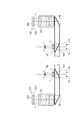
図2は、画像表示部20が備える光学系の構成を示す要部平面図である。図2には説明のため使用者の左眼LE及び右眼REを図示する。
図2に示すように、右表示ユニット22と左表示ユニット24とは、左右対称に構成される。使用者の右眼REに画像を視認させる構成として、右表示ユニット22は、画像光を発するOLED(Organic Light Emitting Diode)ユニット221と、OLEDユニット221が発する画像光Lを導くレンズ群等を備えた右光学系251とを備える。画像光Lは、右光学系251により右導光板26に導かれる。
FIG. 2 is a principal plan view showing the configuration of the optical system provided in the image display unit 20. FIG. 2 shows the user's left eye LE and right eye RE for explanation.
As shown in FIG. 2, the right display unit 22 and the left display unit 24 are configured symmetrically. As a configuration for allowing the user's right eye RE to visually recognize an image, the right display unit 22 includes an OLED (Organic Light Emitting Diode) unit 221 that emits image light, a lens group that guides image light L emitted from the OLED unit 221, and the like. Right optical system 251. The image light L is guided to the right light guide plate 26 by the right optical system 251.

OLEDユニット221は、OLEDパネル223と、OLEDパネル223を駆動するOLED駆動回路225とを有する。OLEDパネル223は、有機エレクトロルミネッセンスにより発光してR(赤)、G(緑)、B(青)の色光をそれぞれ発する発光素子を、マトリクス状に配置して構成される、自発光型の表示パネルである。OLEDパネル223は、R、G、Bの素子を1個ずつ含む単位を1画素として、複数の画素を備え、マトリクス状に配置される画素により画像を形成する。OLED駆動回路225は、制御部150(図5)の制御に従って、OLEDパネル223が備える発光素子の選択及び発光素子への通電を実行して、OLEDパネル223の発光素子を発光させる。OLED駆動回路225は、OLEDパネル223の裏面すなわち発光面の裏側に、ボンディング等により固定される。OLED駆動回路225は、例えばOLEDパネル223を駆動する半導体デバイスで構成され、OLEDパネル223の裏面に固定される基板(図示略)に実装されてもよい。この基板には温度センサー217が実装される。
なお、OLEDパネル223は、白色に発光する発光素子をマトリクス状に配置し、R、G、Bの各色に対応するカラーフィルターを重ねて配置する構成であってもよい。また、R、G、Bの色光をそれぞれ放射する発光素子に加え、W(白)の光を発する発光素子を備えるWRGB構成のOLEDパネル223を用いてもよい。
The OLED unit 221 includes an OLED panel 223 and an OLED drive circuit 225 that drives the OLED panel 223. The OLED panel 223 is a self-luminous display configured by arranging light emitting elements that emit light of R (red), G (green), and B (blue) light by organic electroluminescence in a matrix. It is a panel. The OLED panel 223 includes a plurality of pixels, each of which includes one R, G, and B element, and forms an image with pixels arranged in a matrix. The OLED drive circuit 225 selects a light emitting element included in the OLED panel 223 and energizes the light emitting element under the control of the control unit 150 (FIG. 5), and causes the light emitting element of the OLED panel 223 to emit light. The OLED drive circuit 225 is fixed to the back surface of the OLED panel 223, that is, the back surface of the light emitting surface by bonding or the like. The OLED drive circuit 225 may be formed of a semiconductor device that drives the OLED panel 223, for example, and may be mounted on a substrate (not shown) fixed to the back surface of the OLED panel 223. A temperature sensor 217 is mounted on this substrate.
Note that the OLED panel 223 may have a configuration in which light emitting elements that emit white light are arranged in a matrix, and color filters corresponding to R, G, and B colors are stacked. Further, an OLED panel 223 having a WRGB configuration provided with a light emitting element that emits W (white) light in addition to the light emitting elements that respectively emit R, G, and B color light may be used.

右光学系251は、OLEDパネル223から射出された画像光Lを並行状態の光束にするコリメートレンズを有する。コリメートレンズにより並行状態の光束にされた画像光Lは、右導光板26に入射する。右導光板26の内部において光を導く光路には、画像光Lを反射する複数の反射面が形成される。画像光Lは、右導光板26の内部で複数回の反射を経て右眼RE側に導かれる。右導光板26には、右眼REの眼前に位置するハーフミラー261(反射面)が形成される。画像光Lは、ハーフミラー261で反射して右眼REに向けて右導光板26から射出され、この画像光Lが右眼REの網膜に像を結び、使用者に画像を視認させる。   The right optical system 251 includes a collimator lens that converts the image light L emitted from the OLED panel 223 into a parallel light flux. The image light L converted into a parallel light beam by the collimator lens enters the right light guide plate 26. A plurality of reflecting surfaces that reflect the image light L are formed in an optical path that guides light inside the right light guide plate 26. The image light L is guided to the right eye RE side through a plurality of reflections inside the right light guide plate 26. A half mirror 261 (reflection surface) located in front of the right eye RE is formed on the right light guide plate 26. The image light L is reflected by the half mirror 261 and emitted from the right light guide plate 26 toward the right eye RE. The image light L forms an image on the retina of the right eye RE, and allows the user to visually recognize the image.

また、使用者の左眼LEに画像を視認させる構成として、左表示ユニット24は、画像光を発するOLEDユニット241と、OLEDユニット241が発する画像光Lを導くレンズ群等を備えた左光学系252とを備える。画像光Lは、左光学系252により左導光板28に導かれる。   In addition, as a configuration for allowing the user's left eye LE to visually recognize an image, the left display unit 24 includes a left optical system including an OLED unit 241 that emits image light, a lens group that guides the image light L emitted from the OLED unit 241, and the like. 252. The image light L is guided to the left light guide plate 28 by the left optical system 252.

OLEDユニット241は、OLEDパネル243と、OLEDパネル243を駆動するOLED駆動回路245とを有する。OLEDパネル243は、OLEDパネル223と同様に構成される自発光型の表示パネルである。OLED駆動回路245は、制御部150(図5)の制御に従って、OLEDパネル243が備える発光素子の選択及び発光素子への通電を実行して、OLEDパネル243の発光素子を発光させる。OLED駆動回路245は、OLEDパネル243の裏面すなわち発光面の裏側に、ボンディング等により固定される。OLED駆動回路245は、例えばOLEDパネル243を駆動する半導体デバイスで構成され、OLEDパネル243の裏面に固定される基板(図示略)に実装されてもよい。この基板には、温度センサー239が実装される。   The OLED unit 241 includes an OLED panel 243 and an OLED drive circuit 245 that drives the OLED panel 243. The OLED panel 243 is a self-luminous display panel configured similarly to the OLED panel 223. The OLED driving circuit 245 causes the light emitting elements of the OLED panel 243 to emit light by selecting a light emitting element included in the OLED panel 243 and energizing the light emitting element according to the control of the control unit 150 (FIG. 5). The OLED drive circuit 245 is fixed to the back surface of the OLED panel 243, that is, the back surface of the light emitting surface by bonding or the like. The OLED drive circuit 245 may be configured by a semiconductor device that drives the OLED panel 243, for example, and may be mounted on a substrate (not shown) fixed to the back surface of the OLED panel 243. A temperature sensor 239 is mounted on this substrate.

左光学系252は、OLEDパネル243から射出された画像光Lを並行状態の光束にするコリメートレンズを有する。コリメートレンズにより並行状態の光束にされた画像光Lは、左導光板28に入射する。左導光板28は、画像光Lを反射する複数の反射面が形成された光学素子であり、例えばプリズムである。画像光Lは、左導光板28の内部で複数回の反射を経て左眼LE側に導かれる。左導光板28には、左眼LEの眼前に位置するハーフミラー281(反射面)が形成される。画像光Lは、ハーフミラー281で反射して左眼LEに向けて左導光板28から射出され、この画像光Lが左眼LEの網膜に像を結び、使用者に画像を視認させる。   The left optical system 252 includes a collimating lens that converts the image light L emitted from the OLED panel 243 into a light beam in a parallel state. The image light L converted into a parallel light beam by the collimator lens enters the left light guide plate 28. The left light guide plate 28 is an optical element formed with a plurality of reflecting surfaces that reflect the image light L, and is, for example, a prism. The image light L is guided to the left eye LE side through a plurality of reflections inside the left light guide plate 28. The left light guide plate 28 is formed with a half mirror 281 (reflection surface) located in front of the left eye LE. The image light L is reflected by the half mirror 281 and emitted from the left light guide plate 28 toward the left eye LE. The image light L forms an image on the retina of the left eye LE, and allows the user to visually recognize the image.

この構成によれば、HMD100は、シースルー型の表示装置として機能する。すなわち、使用者の右眼REには、ハーフミラー261で反射した画像光Lと、右導光板26を透過した外光OLとが入射する。また、左眼LEには、ハーフミラー281で反射した画像光Lと、ハーフミラー281を透過した外光OLとが入射する。このように、HMD100は、内部で処理した画像の画像光Lと外光OLとを重ねて使用者の眼に入射させ、使用者にとっては、右導光板26及び左導光板28を透かして外景が見え、この外景に重ねて、画像光Lによる画像が視認される。
ハーフミラー261、281は、右表示ユニット22及び左表示ユニット24がそれぞれ出力する画像光を反射して画像を取り出す画像取り出し部であり、表示部ということができる。
According to this configuration, the HMD 100 functions as a see-through display device. That is, the image light L reflected by the half mirror 261 and the external light OL transmitted through the right light guide plate 26 are incident on the user's right eye RE. Further, the image light L reflected by the half mirror 281 and the external light OL transmitted through the half mirror 281 are incident on the left eye LE. In this way, the HMD 100 superimposes the image light L of the internally processed image and the external light OL so as to enter the user's eyes, and for the user, the outside light can be seen through the right light guide plate 26 and the left light guide plate 28. The image by the image light L is visually recognized over the outside scene.
The half mirrors 261 and 281 are image extraction units that extract image by reflecting image light output from the right display unit 22 and the left display unit 24, respectively, and can be called display units.

なお、左光学系252と左導光板28とを総称して「左導光部」とも呼び、右光学系251と右導光板26とを総称して「右導光部」と呼ぶ。右導光部及び左導光部の構成は上記の例に限定されず、画像光を用いて使用者の眼前に虚像を形成する限りにおいて任意の方式を用いることができ、例えば、回折格子を用いても良いし、半透過反射膜を用いても良い。   The left optical system 252 and the left light guide plate 28 are collectively referred to as a “left light guide”, and the right optical system 251 and the right light guide plate 26 are collectively referred to as a “right light guide”. The configuration of the right light guide and the left light guide is not limited to the above example, and any method can be used as long as a virtual image is formed in front of the user's eyes using image light. It may be used, or a semi-transmissive reflective film may be used.

図1に戻り、制御装置10と画像表示部20とは、接続ケーブル40により接続される。接続ケーブル40は、制御装置10の下部に設けられるコネクター(図示略)に着脱可能に接続され、左保持部23の先端から、画像表示部20の内部に設けられる各種回路に接続する。接続ケーブル40は、デジタルデータを伝送するメタルケーブルまたは光ファイバーケーブルを有し、アナログ信号を伝送するメタルケーブルを有していてもよい。接続ケーブル40の途中には、コネクター46が設けられる。コネクター46は、ステレオミニプラグを接続するジャックであり、コネクター46と制御装置10とは、例えばアナログ音声信号を伝送するラインで接続される。図1に示す構成例では、ステレオヘッドホンを構成する右イヤホン32と左イヤホン34、及び、マイク63を有するヘッドセット30が、コネクター46に接続される。   Returning to FIG. 1, the control device 10 and the image display unit 20 are connected by a connection cable 40. The connection cable 40 is detachably connected to a connector (not shown) provided at the lower part of the control device 10, and is connected to various circuits provided in the image display unit 20 from the tip of the left holding unit 23. The connection cable 40 includes a metal cable or optical fiber cable that transmits digital data, and may include a metal cable that transmits an analog signal. A connector 46 is provided in the middle of the connection cable 40. The connector 46 is a jack for connecting a stereo mini-plug, and the connector 46 and the control device 10 are connected by a line for transmitting an analog audio signal, for example. In the configuration example shown in FIG. 1, a headset 30 having a right earphone 32 and a left earphone 34 and a microphone 63 constituting a stereo headphone is connected to a connector 46.

マイク63は、例えば図1に示すように、マイク63の集音部が使用者の視線方向を向くように配置され、音声を集音して、音声信号を音声インターフェイス182(図4)に出力する。マイク63は、例えばモノラルマイクであってもステレオマイクであってもよく、指向性を有するマイクであってもよいし、無指向性のマイクであってもよい。   For example, as shown in FIG. 1, the microphone 63 is arranged so that the sound collection unit of the microphone 63 faces the user's line of sight, collects sound, and outputs a sound signal to the sound interface 182 (FIG. 4). To do. For example, the microphone 63 may be a monaural microphone or a stereo microphone, may be a directional microphone, or may be an omnidirectional microphone.

制御装置10は、使用者により操作される被操作部として、ボタン11、LEDインジケーター12、トラックパッド14、上下キー15、切替スイッチ16、及び電源スイッチ18を備える。
ボタン11は、制御装置10が実行するオペレーティングシステム143(図5)の操作等を行うためのメニューキー、ホームキー、戻るキー等を含み、特に、これらのキーやスイッチのうち押圧操作により変位するものを含む。LEDインジケーター12は、HMD100の動作状態に対応して点灯し、或いは点滅する。上下キー15は、右イヤホン32及び左イヤホン34から出力する音量の増減の指示入力や、画像表示部20の表示の明るさの増減の指示入力に利用される。切替スイッチ16は、上下キー15の操作に対応する入力を切り替えるスイッチである。電源スイッチ18は、HMD100の電源のオン/オフを切り替えるスイッチであり、例えばスライドスイッチで構成される。
The control device 10 includes a button 11, an LED indicator 12, a track pad 14, an up / down key 15, a changeover switch 16, and a power switch 18 as operated parts operated by a user.
The button 11 includes a menu key, a home key, a return key, and the like for operating the operating system 143 (FIG. 5) executed by the control device 10, and in particular, is displaced by a pressing operation of these keys and switches. Including things. The LED indicator 12 lights up or flashes in accordance with the operating state of the HMD 100. The up / down key 15 is used to input an instruction to increase / decrease the volume output from the right earphone 32 and the left earphone 34 and to input an instruction to increase / decrease the display brightness of the image display unit 20. The changeover switch 16 is a switch for changing an input corresponding to the operation of the up / down key 15. The power switch 18 is a switch for switching on / off the power of the HMD 100, and is configured by a slide switch, for example.

トラックパッド14は、接触操作を検出する操作面を有し、操作面に対する操作に応じて操作信号を出力する。操作面における検出方式は限定されず、静電式、圧力検出式、光学式等を採用できる。
また、制御装置10は、図示はしないが、タッチ操作を検出するタッチ操作部を備える。タッチ操作部は操作により変位するスイッチ等を持たず、例えば操作位置と操作内容を示すアイコン等が画面による表示や印刷で配置される。このタッチ操作部への接触(タッチ操作)は、後述するタッチセンサー13(図4)により検出される。
The track pad 14 has an operation surface for detecting a contact operation, and outputs an operation signal according to an operation on the operation surface. The detection method on the operation surface is not limited, and an electrostatic method, a pressure detection method, an optical method, or the like can be adopted.
Moreover, although not shown in figure, the control apparatus 10 is provided with the touch operation part which detects touch operation. The touch operation unit does not have a switch or the like that is displaced by the operation, and for example, an icon indicating an operation position and an operation content is arranged by display or printing on the screen. This contact (touch operation) with the touch operation unit is detected by a touch sensor 13 (FIG. 4) described later.

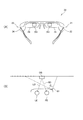
図3は、画像表示部20の要部構成を示す図であり、図3(A)は画像表示部20を使用者の頭部側から見た要部斜視図、図3(B)はカメラ61の画角の説明図である。なお、図3(A)では接続ケーブル40の図示を省略する。   FIG. 3 is a diagram illustrating a configuration of a main part of the image display unit 20, FIG. 3A is a main part perspective view of the image display unit 20 as viewed from the user's head side, and FIG. 3B is a camera. It is explanatory drawing of the angle of view of 61. FIG. Note that the connection cable 40 is not shown in FIG.

図3(A)は、画像表示部20の使用者の頭部に接する側、言い換えれば使用者の右眼RE及び左眼LEに見える側である。別の言い方をすれば、右導光板26及び左導光板28の裏側が見えている。
図3(A)では、使用者の右眼REに画像光を照射するハーフミラー261、及び、左眼LEに画像光を照射するハーフミラー281が、略四角形の領域として見える。また、ハーフミラー261、281を含む右導光板26及び左導光板28の全体が、上述したように外光を透過する。このため、使用者には、右導光板26及び左導光板28の全体を透過して外景が視認され、ハーフミラー261、281の位置に矩形の表示画像が視認される。
FIG. 3A shows the side of the image display unit 20 in contact with the user's head, in other words, the side visible to the user's right eye RE and left eye LE. In other words, the back sides of the right light guide plate 26 and the left light guide plate 28 are visible.
In FIG. 3A, the half mirror 261 that irradiates the user's right eye RE with the image light and the half mirror 281 that irradiates the left eye LE with the image light appear as substantially rectangular areas. Further, the entire right light guide plate 26 and left light guide plate 28 including the half mirrors 261 and 281 transmit external light as described above. For this reason, the user sees the outside scene through the entire right light guide plate 26 and the left light guide plate 28, and sees a rectangular display image at the positions of the half mirrors 261 and 281.

カメラ61は、上記のように画像表示部20において右側の端部に配置され、使用者の両眼が向く方向、すなわち使用者にとって前方を撮像する。図3(B)は、カメラ61の位置を、使用者の右眼RE及び左眼LEとともに平面視で模式的に示す図である。カメラ61の画角(撮像範囲)をCで示す。なお、図3(B)には水平方向の画角Cを示すが、カメラ61の実際の画角は一般的なデジタルカメラと同様に上下方向にも拡がる。   The camera 61 is arranged at the right end of the image display unit 20 as described above, and images the direction in which both eyes of the user face, that is, the front for the user. FIG. 3B is a diagram schematically showing the position of the camera 61 in plan view together with the user's right eye RE and left eye LE. An angle of view (imaging range) of the camera 61 is indicated by C. FIG. 3B shows a horizontal angle of view C, but the actual angle of view of the camera 61 extends in the vertical direction as in a general digital camera.

カメラ61の光軸は、右眼RE及び左眼LEの視線方向を含む方向とされる。使用者がHMD100を装着した状態で視認できる外景は、無限遠とは限らない。例えば図3(B)に示すように、使用者が両眼で対象物OBを注視すると、使用者の視線は、図中符号RD、LDに示すように対象物OBに向けられる。この場合、使用者から対象物OBまでの距離は、30cm〜10m程度であることが多く、1m〜4m程度であることが、より多い。そこで、HMD100について、通常使用時における使用者から対象物OBまでの距離の上限、及び下限の目安を定めてもよい。この目安は調査や実験により求めてもよいし使用者が設定してもよい。カメラ61の光軸、及び画角は、通常使用時における対象物OBまでの距離が、設定された上限の目安に相当する場合、及び、下限の目安に相当する場合に、この対象物OBが画角に含まれるように、設定されることが好ましい。   The optical axis of the camera 61 is a direction including the line-of-sight directions of the right eye RE and the left eye LE. The outside scene that the user can visually recognize in a state where the HMD 100 is worn is not always at infinity. For example, as shown in FIG. 3B, when the user gazes at the object OB with both eyes, the user's line of sight is directed toward the object OB as indicated by reference signs RD and LD in the figure. In this case, the distance from the user to the object OB is often about 30 cm to 10 m, and more often about 1 m to 4 m. Therefore, for the HMD 100, an upper limit and a lower limit guideline for the distance from the user to the object OB during normal use may be set. This standard may be obtained by investigation or experiment, or may be set by the user. The optical axis and the angle of view of the camera 61 are determined when the distance to the object OB during normal use corresponds to the set upper limit guide and when the target OB corresponds to the lower limit guide. It is preferably set so as to be included in the angle of view.

また、一般に、人間の視野角は水平方向におよそ200度、垂直方向におよそ125度とされ、そのうち情報受容能力に優れる有効視野は水平方向に30度、垂直方向に20度程度である。さらに、人間が注視する注視点が迅速に安定して見える安定注視野は、水平方向に60〜90度、垂直方向に45度〜70度程度とされている。この場合、注視点が、図3(B)の対象物OBであるとき、視線RD、LDを中心として水平方向に30度、垂直方向に20度程度が有効視野である。また、水平方向に60〜90度、垂直方向に45度〜70度程度が安定注視野であり、水平方向に約200度、垂直方向に約125度が視野角となる。さらに、使用者が画像表示部20を透過して右導光板26及び左導光板28を透過して視認する実際の視野を、実視野(FOV:Field Of View)と呼ぶことができる。図1及び図2に示す本実施形態の構成で、実視野は、右導光板26及び左導光板28を透過して使用者が視認する実際の視野に相当する。実視野は、視野角及び安定注視野より狭いが、有効視野より広い。   In general, the viewing angle of a human is about 200 degrees in the horizontal direction and about 125 degrees in the vertical direction, and of these, the effective field of view with excellent information receiving capability is about 30 degrees in the horizontal direction and about 20 degrees in the vertical direction. Furthermore, the stable gaze field in which the gaze point that the human gazes at appears to be quickly and stably is about 60 to 90 degrees in the horizontal direction and about 45 to 70 degrees in the vertical direction. In this case, when the gazing point is the object OB in FIG. 3B, the effective visual field is about 30 degrees in the horizontal direction and about 20 degrees in the vertical direction around the lines of sight RD and LD. Further, the stable viewing field is about 60 to 90 degrees in the horizontal direction and about 45 to 70 degrees in the vertical direction, and the viewing angle is about 200 degrees in the horizontal direction and about 125 degrees in the vertical direction. Furthermore, the actual field of view that the user perceives through the image display unit 20 and through the right light guide plate 26 and the left light guide plate 28 can be referred to as a real field of view (FOV). In the configuration of the present embodiment shown in FIGS. 1 and 2, the actual visual field corresponds to an actual visual field that is transmitted through the right light guide plate 26 and the left light guide plate 28 and visually recognized by the user. The real field of view is narrower than the viewing angle and stable field of view, but wider than the effective field of view.

カメラ61の画角Cは、使用者の視野よりも広い範囲を撮像可能であることが好ましく、具体的には、画角Cが、少なくとも使用者の有効視野よりも広いことが好ましい。また、画角Cが、使用者の実視野よりも広いことが、より好ましい。さらに好ましくは、画角Cが、使用者の安定注視野よりも広く、最も好ましくは、画角Cが使用者の両眼の視野角よりも広い。   The angle of view C of the camera 61 is preferably capable of capturing a wider range than the user's field of view, and specifically, the angle of view C is preferably at least wider than the effective field of view of the user. Further, it is more preferable that the angle of view C is wider than the actual field of view of the user. More preferably, the angle of view C is wider than the stable viewing field of the user, and most preferably, the angle of view C is wider than the viewing angle of both eyes of the user.

カメラ61が、撮像レンズとして、いわゆる広角レンズを備え、広い画角を撮像できる構成としてもよい。広角レンズには、超広角レンズ、準広角レンズと呼ばれるレンズを含んでもよいし、単焦点レンズであってもズームレンズであってもよく、複数のレンズからなるレンズ群をカメラ61が備える構成であってもよい。   The camera 61 may include a so-called wide-angle lens as an imaging lens so that a wide angle of view can be captured. The wide-angle lens may include a lens called a super-wide-angle lens or a quasi-wide-angle lens, may be a single focus lens or a zoom lens, and the camera 61 includes a lens group including a plurality of lenses. There may be.

図4は、HMD100を構成する各部の構成を示すブロック図である。
制御装置10は、プログラムを実行してHMD100を制御するメインプロセッサー140を備える。メインプロセッサー140には、メモリー118及び不揮発性記憶部121が接続される。また、メインプロセッサー140には、入力装置としてトラックパッド14及び操作部110が接続される。また、メインプロセッサー140には、センサー類として、6軸センサー111、磁気センサー113、及び、GPS115が接続される。また、メインプロセッサー140には、通信部117、音声コーデック180、外部コネクター184、外部メモリーインターフェイス186、USBコネクター188、センサーハブ192、及び、FPGA194が接続される。これらは外部とのインターフェイスとして機能する。
FIG. 4 is a block diagram illustrating a configuration of each unit included in the HMD 100.
The control device 10 includes a main processor 140 that executes a program and controls the HMD 100. A memory 118 and a non-volatile storage unit 121 are connected to the main processor 140. The main processor 140 is connected to the track pad 14 and the operation unit 110 as input devices. In addition, a six-axis sensor 111, a magnetic sensor 113, and a GPS 115 are connected to the main processor 140 as sensors. The main processor 140 is connected to a communication unit 117, an audio codec 180, an external connector 184, an external memory interface 186, a USB connector 188, a sensor hub 192, and an FPGA 194. These function as an interface with the outside.

メインプロセッサー140は、制御装置10が内蔵するコントローラー基板120に実装される。コントローラー基板120には、メインプロセッサー140に加えて、メモリー118、不揮発性記憶部121等が実装されてもよい。本実施形態では、6軸センサー111、磁気センサー113、GPS115、通信部117、メモリー118、不揮発性記憶部121、音声コーデック180等がコントローラー基板120に実装される。また、外部コネクター184、外部メモリーインターフェイス186、USBコネクター188、センサーハブ192、FPGA194、及びインターフェイス196をコントローラー基板120に実装した構成であってもよい。   The main processor 140 is mounted on the controller board 120 built in the control device 10. In addition to the main processor 140, a memory 118, a nonvolatile storage unit 121, and the like may be mounted on the controller board 120. In the present embodiment, a six-axis sensor 111, a magnetic sensor 113, a GPS 115, a communication unit 117, a memory 118, a nonvolatile storage unit 121, an audio codec 180, and the like are mounted on the controller board 120. Further, the external connector 184, the external memory interface 186, the USB connector 188, the sensor hub 192, the FPGA 194, and the interface 196 may be mounted on the controller board 120.

メモリー118は、メインプロセッサー140がプログラムを実行する場合に、実行されるプログラム、及び、処理されるデータを一時的に記憶するワークエリアを構成する。不揮発性記憶部121は、フラッシュメモリーやeMMC(Embedded Multi Media Card)で構成される。不揮発性記憶部121は、メインプロセッサー140が実行するプログラムや、メインプロセッサー140がプログラムを実行して処理する各種データを記憶する。   The memory 118 constitutes a work area that temporarily stores a program to be executed and data to be processed when the main processor 140 executes the program. The nonvolatile storage unit 121 includes a flash memory or an eMMC (Embedded Multi Media Card). The nonvolatile storage unit 121 stores a program executed by the main processor 140 and various data processed by the main processor 140 executing the program.

メインプロセッサー140は、トラックパッド14から入力される操作信号に基づいて、トラックパッド14の操作面に対する接触操作を検出し、操作位置を取得する。
操作部110は、ボタン11、タッチセンサー13、およびLED表示部17を含む。タッチセンサー13は、制御装置10が有するタッチ操作部へのタッチ操作を検出する。ボタン11の操作が行われた場合、及び、タッチセンサー13がタッチ操作を検出した場合、操作部110からメインプロセッサー140に対し、操作信号が出力される。
LED表示部17は、LEDインジケーター12(図1)が備えるLED、及び、このLEDを点灯させる駆動回路を含む。LED表示部17は、メインプロセッサー140の制御に従って、LEDを点灯、点滅、消灯させる。また、LED表示部17は、LEDが発光する輝度を制御してもよい。また、LED表示部17は、赤、青、緑の3色のLEDを備える構成であってもよく、この場合、各色のLEDの輝度を調整することによって任意の色でLEDインジケーター12を発光させてもよい。
The main processor 140 detects a touch operation on the operation surface of the track pad 14 based on an operation signal input from the track pad 14 and acquires an operation position.
The operation unit 110 includes a button 11, a touch sensor 13, and an LED display unit 17. The touch sensor 13 detects a touch operation on the touch operation unit included in the control device 10. When the operation of the button 11 is performed and when the touch sensor 13 detects the touch operation, an operation signal is output from the operation unit 110 to the main processor 140.
The LED display unit 17 includes an LED included in the LED indicator 12 (FIG. 1) and a drive circuit that lights the LED. The LED display unit 17 turns on, blinks, and turns off the LED according to the control of the main processor 140. Moreover, the LED display part 17 may control the brightness | luminance which LED light-emits. The LED display unit 17 may be configured to include LEDs of three colors, red, blue, and green. In this case, the LED indicator 12 is caused to emit light in an arbitrary color by adjusting the luminance of the LED of each color. May be.

6軸センサー111は、3軸加速度センサー、及び、3軸ジャイロ(角速度)センサーを備えるモーションセンサー(慣性センサー)である。6軸センサー111は、上記のセンサーがモジュール化されたIMU(Inertial Measurement Unit)を採用してもよい。
磁気センサー113は、例えば、3軸の地磁気センサーである。
GPS(Global Positioning System)115は、図示しないGPSアンテナを備え、GPS衛星から送信される無線信号を受信して、制御装置10の現在位置の座標を検出する。
6軸センサー111、磁気センサー113及びGPS115は、検出値を、予め指定されたサンプリング周期に従ってメインプロセッサー140に出力する。或いは、6軸センサー111、磁気センサー113及びGPS115は、メインプロセッサー140の要求に応じて、メインプロセッサー140により指定されたタイミングで、検出値をメインプロセッサー140に出力する。
The 6-axis sensor 111 is a motion sensor (inertial sensor) including a 3-axis acceleration sensor and a 3-axis gyro (angular velocity) sensor. The 6-axis sensor 111 may employ an IMU (Inertial Measurement Unit) in which the above sensors are modularized.
The magnetic sensor 113 is, for example, a triaxial geomagnetic sensor.
A GPS (Global Positioning System) 115 includes a GPS antenna (not shown), receives a radio signal transmitted from a GPS satellite, and detects the coordinates of the current position of the control device 10.
The six-axis sensor 111, the magnetic sensor 113, and the GPS 115 output detection values to the main processor 140 according to a sampling period specified in advance. Alternatively, the six-axis sensor 111, the magnetic sensor 113, and the GPS 115 output detection values to the main processor 140 at a timing designated by the main processor 140 in response to a request from the main processor 140.

通信部117は、外部の機器との間で無線通信を実行する。通信部117は、アンテナ、RF回路、ベースバンド回路、通信制御回路等を備えて構成され、或いはこれらが統合されたデバイスで構成される。通信部117は、例えば、Bluetooth(登録商標)、無線LAN(Wi−Fi(登録商標)を含む)等の規格に準拠した無線通信を行う。
音声インターフェイス182は、音声信号を入出力するインターフェイスである。本実施形態では、音声インターフェイス182は、接続ケーブル40に設けられたコネクター46(図1)を含む。音声コーデック180は、音声インターフェイス182に接続され、音声インターフェイス182を介して入出力される音声信号のエンコード/デコードを行う。また、音声コーデック180はアナログ音声信号からデジタル音声データへの変換を行うA/Dコンバーター、及び、その逆の変換を行うD/Aコンバーターを備えてもよい。例えば、本実施形態のHMD100は、音声を右イヤホン32及び左イヤホン34により出力し、マイク63で集音する。音声コーデック180は、メインプロセッサー140が出力するデジタル音声データをアナログ音声信号に変換して、音声インターフェイス182を介して出力する。また、音声コーデック180は、音声インターフェイス182に入力されるアナログ音声信号をデジタル音声データに変換してメインプロセッサー140に出力する。
The communication unit 117 performs wireless communication with an external device. The communication unit 117 includes an antenna, an RF circuit, a baseband circuit, a communication control circuit, and the like, or a device in which these are integrated. The communication unit 117 performs wireless communication conforming to standards such as Bluetooth (registered trademark) and wireless LAN (including Wi-Fi (registered trademark)).
The audio interface 182 is an interface for inputting and outputting audio signals. In the present embodiment, the audio interface 182 includes a connector 46 (FIG. 1) provided on the connection cable 40. The audio codec 180 is connected to the audio interface 182 and encodes / decodes an audio signal input / output via the audio interface 182. The audio codec 180 may include an A / D converter that converts analog audio signals to digital audio data, and a D / A converter that performs the reverse conversion. For example, the HMD 100 according to the present embodiment outputs sound by the right earphone 32 and the left earphone 34 and collects sound by the microphone 63. The audio codec 180 converts the digital audio data output from the main processor 140 into an analog audio signal and outputs the analog audio signal via the audio interface 182. The audio codec 180 converts an analog audio signal input to the audio interface 182 into digital audio data and outputs the digital audio data to the main processor 140.

外部コネクター184は、メインプロセッサー140と通信する外部の装置を接続するコネクターである。外部コネクター184は、例えば、外部の装置をメインプロセッサー140に接続して、メインプロセッサー140が実行するプログラムのデバッグや、HMD100の動作のログの収集を行う場合に、この外部の装置を接続するインターフェイスである。
外部メモリーインターフェイス186は、可搬型のメモリーデバイスを接続可能なインターフェイスであり、例えば、カード型記録媒体を装着してデータの読取が可能なメモリーカードスロットとインターフェイス回路とを含む。この場合のカード型記録媒体のサイズ、形状、規格は制限されず、適宜に変更可能である。
USB(Universal Serial Bus)コネクター188は、USB規格に準拠したコネクターとインターフェイス回路とを備え、USBメモリーデバイス、スマートフォン、コンピューター等を接続できる。USBコネクター188のサイズや形状、適合するUSB規格のバージョンは適宜に選択、変更可能である。
The external connector 184 is a connector that connects an external device that communicates with the main processor 140. The external connector 184 is an interface for connecting an external device when, for example, an external device is connected to the main processor 140 to debug a program executed by the main processor 140 or collect a log of the operation of the HMD 100. It is.
The external memory interface 186 is an interface to which a portable memory device can be connected. For example, the external memory interface 186 includes a memory card slot in which a card type recording medium is mounted and data can be read and an interface circuit. In this case, the size, shape and standard of the card type recording medium are not limited and can be changed as appropriate.
A USB (Universal Serial Bus) connector 188 includes a connector conforming to the USB standard and an interface circuit, and can connect a USB memory device, a smartphone, a computer, and the like. The size and shape of the USB connector 188 and the compatible USB standard version can be appropriately selected and changed.

また、HMD100は、バイブレーター19を備える。バイブレーター19は、モーター(図示略)、偏心した回転子(図示略)等を備え、メインプロセッサー140の制御に従って振動を発生する。HMD100は、例えば、操作部110に対する操作を検出した場合、HMD100の電源がオン/オフされる場合等に、所定の振動パターンでバイブレーター19により振動を発生する。   Further, the HMD 100 includes a vibrator 19. The vibrator 19 includes a motor (not shown), an eccentric rotor (not shown), and the like, and generates vibrations under the control of the main processor 140. The HMD 100 generates vibration by the vibrator 19 with a predetermined vibration pattern, for example, when an operation on the operation unit 110 is detected, or when the power of the HMD 100 is turned on / off.

センサーハブ192及びFPGA194は、インターフェイス(I/F)196を介して、画像表示部20を接続される。センサーハブ192は、画像表示部20が備える各種センサーの検出値を取得してメインプロセッサー140に出力する。また、FPGA194は、メインプロセッサー140と画像表示部20の各部との間で送受信するデータの処理、及び、インターフェイス196を介した伝送を実行する。   The sensor hub 192 and the FPGA 194 are connected to the image display unit 20 via an interface (I / F) 196. The sensor hub 192 acquires detection values of various sensors included in the image display unit 20 and outputs them to the main processor 140. The FPGA 194 executes processing of data transmitted and received between the main processor 140 and each unit of the image display unit 20 and transmission via the interface 196.

画像表示部20の右表示ユニット22及び左表示ユニット24は、それぞれ、制御装置10に接続される。図1に示すように、HMD100では左保持部23に接続ケーブル40が接続され、この接続ケーブル40に繋がる配線が画像表示部20内部に敷設され、右表示ユニット22と左表示ユニット24のそれぞれが制御装置10に接続される。   The right display unit 22 and the left display unit 24 of the image display unit 20 are each connected to the control device 10. As shown in FIG. 1, in the HMD 100, a connection cable 40 is connected to the left holding unit 23, wiring connected to the connection cable 40 is laid inside the image display unit 20, and each of the right display unit 22 and the left display unit 24 is Connected to the control device 10.

右表示ユニット22は、表示ユニット基板210を有する。表示ユニット基板210には、インターフェイス196に接続されるインターフェイス(I/F)211、インターフェイス211を介して制御装置10から入力されるデータを受信する受信部(Rx)213、及び、EEPROM215(記憶部)が実装される。
インターフェイス211は、受信部213、EEPROM215、温度センサー217、カメラ61、照度センサー65、及びLEDインジケーター67を、制御装置10に接続する。
The right display unit 22 includes a display unit substrate 210. The display unit substrate 210 includes an interface (I / F) 211 connected to the interface 196, a receiving unit (Rx) 213 that receives data input from the control device 10 via the interface 211, and an EEPROM 215 (storage unit) ) Is implemented.
The interface 211 connects the receiving unit 213, the EEPROM 215, the temperature sensor 217, the camera 61, the illuminance sensor 65, and the LED indicator 67 to the control device 10.

EEPROM(Electrically Erasable Programmable Read-Only Memory)215は、各種のデータをメインプロセッサー140が読み取り可能に記憶する。EEPROM215は、例えば、画像表示部20が備えるOLEDユニット221、241の発光特性や表示特性に関するデータ、右表示ユニット22または左表示ユニット24が備えるセンサーの特性に関するデータなどを記憶する。具体的には、OLEDユニット221、241のガンマ補正に係るパラメーター、温度センサー217、239の検出値を補償するデータ等を記憶する。これらのデータは、HMD100の工場出荷時の検査によって生成され、EEPROM215に書き込まれ、出荷後はメインプロセッサー140がEEPROM215のデータを利用して処理を行える。   An EEPROM (Electrically Erasable Programmable Read-Only Memory) 215 stores various data so that the main processor 140 can read the data. The EEPROM 215 stores, for example, data relating to the light emission characteristics and display characteristics of the OLED units 221 and 241 provided in the image display unit 20, data relating to the characteristics of sensors provided in the right display unit 22 or the left display unit 24, and the like. Specifically, parameters relating to gamma correction of the OLED units 221, 241 and data for compensating the detection values of the temperature sensors 217, 239 are stored. These data are generated by the factory inspection of the HMD 100 and written in the EEPROM 215. After the shipment, the main processor 140 can perform processing using the data in the EEPROM 215.

カメラ61は、インターフェイス211を介して入力される信号に従って撮像を実行し、撮像画像データ、或いは、撮像結果を示す信号を制御装置10に出力する。
照度センサー65は、図1に示すように、前部フレーム27の端部ERに設けられ、画像表示部20を装着する使用者の前方からの外光を受光するよう配置される。照度センサー65は、受光量(受光強度)に対応する検出値を出力する。
LEDインジケーター67は、図1に示すように、前部フレーム27の端部ERにおいてカメラ61の近傍に配置される。LEDインジケーター67は、カメラ61による撮像を実行中に点灯して、撮像中であることを報知する。
The camera 61 executes imaging according to a signal input via the interface 211 and outputs captured image data or a signal indicating the imaging result to the control device 10.
As shown in FIG. 1, the illuminance sensor 65 is provided at the end ER of the front frame 27 and is arranged to receive external light from the front of the user wearing the image display unit 20. The illuminance sensor 65 outputs a detection value corresponding to the amount of received light (received light intensity).
As shown in FIG. 1, the LED indicator 67 is disposed near the camera 61 at the end ER of the front frame 27. The LED indicator 67 is lit during execution of imaging by the camera 61 to notify that imaging is in progress.

温度センサー217は、温度を検出し、検出温度に対応する電圧値あるいは抵抗値を、検出値として出力する。温度センサー217は、OLEDパネル223(図3)の裏面側に実装される。温度センサー217は、例えばOLED駆動回路225と同一の基板に実装されてもよい。この構成により、温度センサー217は、主としてOLEDパネル223の温度を検出する。   The temperature sensor 217 detects the temperature and outputs a voltage value or a resistance value corresponding to the detected temperature as a detected value. The temperature sensor 217 is mounted on the back side of the OLED panel 223 (FIG. 3). For example, the temperature sensor 217 may be mounted on the same substrate as the OLED drive circuit 225. With this configuration, the temperature sensor 217 mainly detects the temperature of the OLED panel 223.

受信部213は、インターフェイス211を介してメインプロセッサー140が送信するデータを受信する。受信部213は、OLEDユニット221で表示する画像の画像データを受信した場合に、受信した画像データを、OLED駆動回路225(図2)に出力する。   The receiving unit 213 receives data transmitted from the main processor 140 via the interface 211. When receiving the image data of the image displayed on the OLED unit 221, the receiving unit 213 outputs the received image data to the OLED drive circuit 225 (FIG. 2).

左表示ユニット24は、表示ユニット基板210を有する。表示ユニット基板210には、インターフェイス196に接続されるインターフェイス(I/F)231、インターフェイス231を介して制御装置10から入力されるデータを受信する受信部(Rx)233が実装される。また、表示ユニット基板210には、6軸センサー235、及び、磁気センサー237が実装される。
インターフェイス231は、受信部233、6軸センサー235、磁気センサー237、及び温度センサー239を、制御装置10に接続する。
The left display unit 24 includes a display unit substrate 210. On the display unit substrate 210, an interface (I / F) 231 connected to the interface 196 and a receiving unit (Rx) 233 that receives data input from the control device 10 via the interface 231 are mounted. In addition, a 6-axis sensor 235 and a magnetic sensor 237 are mounted on the display unit substrate 210.
The interface 231 connects the receiving unit 233, the six-axis sensor 235, the magnetic sensor 237, and the temperature sensor 239 to the control device 10.

6軸センサー235は、3軸加速度センサー、及び、3軸ジャイロ(角速度)センサーを備えるモーションセンサー(慣性センサー)である。6軸センサー235は、上記のセンサーがモジュール化されたIMU(Inertial Measurement Unit)を採用してもよい。
磁気センサー237は、例えば、3軸の地磁気センサーである。
The 6-axis sensor 235 is a motion sensor (inertial sensor) including a 3-axis acceleration sensor and a 3-axis gyro (angular velocity) sensor. The 6-axis sensor 235 may employ an IMU (Inertial Measurement Unit) in which the above sensors are modularized.
The magnetic sensor 237 is, for example, a triaxial geomagnetic sensor.

温度センサー239は、温度を検出し、検出温度に対応する電圧値あるいは抵抗値を、検出値として出力する。温度センサー239は、OLEDパネル243(図3)の裏面側に実装される。温度センサー239は、例えばOLED駆動回路245と同一の基板に実装されてもよい。この構成により、温度センサー239は、主としてOLEDパネル243の温度を検出する。
また、温度センサー239が、OLEDパネル243或いはOLED駆動回路245に内蔵されてもよい。また、上記基板は半導体基板であってもよい。具体的には、OLEDパネル243が、Si−OLEDとして、OLED駆動回路245等とともに統合半導体チップ上の集積回路として実装される場合、この半導体チップに温度センサー239を実装してもよい。
The temperature sensor 239 detects the temperature and outputs a voltage value or a resistance value corresponding to the detected temperature as a detected value. The temperature sensor 239 is mounted on the back side of the OLED panel 243 (FIG. 3). The temperature sensor 239 may be mounted on the same substrate as the OLED drive circuit 245, for example. With this configuration, the temperature sensor 239 mainly detects the temperature of the OLED panel 243.
Further, the temperature sensor 239 may be incorporated in the OLED panel 243 or the OLED drive circuit 245. The substrate may be a semiconductor substrate. Specifically, when the OLED panel 243 is mounted as an Si-OLED as an integrated circuit on an integrated semiconductor chip together with the OLED drive circuit 245 and the like, the temperature sensor 239 may be mounted on the semiconductor chip.

右表示ユニット22が備えるカメラ61、照度センサー65、温度センサー217、及び、左表示ユニット24が備える6軸センサー235、磁気センサー237、温度センサー239は、センサーハブ192に接続される。センサーハブ192は、メインプロセッサー140の制御に従って各センサーのサンプリング周期の設定及び初期化を行う。センサーハブ192は、各センサーのサンプリング周期に合わせて、各センサーへの通電、制御データの送信、検出値の取得等を実行する。また、センサーハブ192は、予め設定されたタイミングで、右表示ユニット22及び左表示ユニット24が備える各センサーの検出値を、メインプロセッサー140に出力する。センサーハブ192は、各センサーの検出値を、メインプロセッサー140に対する出力のタイミングに合わせて一時的に保持する機能を備えてもよい。また、センサーハブ192は、各センサーの出力値の信号形式、或いはデータ形式の相違に対応し、統一されたデータ形式のデータに変換して、メインプロセッサー140に出力する機能を備えてもよい。
また、センサーハブ192は、メインプロセッサー140の制御に従ってLEDインジケーター67への通電を開始及び停止させ、カメラ61が撮像を開始及び終了するタイミングに合わせて、LEDインジケーター67を点灯または点滅させる。
The camera 61, the illuminance sensor 65, the temperature sensor 217, and the 6-axis sensor 235, the magnetic sensor 237, and the temperature sensor 239 included in the left display unit 24 are connected to the sensor hub 192. The sensor hub 192 sets and initializes the sampling period of each sensor according to the control of the main processor 140. The sensor hub 192 executes energization to each sensor, transmission of control data, acquisition of a detection value, and the like in accordance with the sampling period of each sensor. The sensor hub 192 outputs detection values of the sensors included in the right display unit 22 and the left display unit 24 to the main processor 140 at a preset timing. The sensor hub 192 may have a function of temporarily holding the detection value of each sensor in accordance with the output timing to the main processor 140. In addition, the sensor hub 192 may have a function of converting to data in a unified data format and outputting the data to the main processor 140 in response to a difference in signal format or data format of the output value of each sensor.
The sensor hub 192 starts and stops energization of the LED indicator 67 according to the control of the main processor 140, and lights or blinks the LED indicator 67 in accordance with the timing when the camera 61 starts and ends imaging.

制御装置10は、電源部130を備え、電源部130から供給される電力により動作する。電源部130は充電可能なバッテリー132、及び、バッテリー132の残容量の検出およびバッテリー132への充電の制御を行う電源制御回路134を備える。電源制御回路134はメインプロセッサー140に接続され、バッテリー132の残容量の検出値、或いは電圧の検出値をメインプロセッサー140に出力する。また、電源部130が供給する電力に基づき、制御装置10から画像表示部20に電力を供給してもよい。また、電源部130から制御装置10の各部及び画像表示部20への電力の供給状態を、メインプロセッサー140が制御可能な構成としてもよい。   The control device 10 includes a power supply unit 130 and operates with power supplied from the power supply unit 130. The power supply unit 130 includes a rechargeable battery 132 and a power supply control circuit 134 that detects the remaining capacity of the battery 132 and controls the charging of the battery 132. The power control circuit 134 is connected to the main processor 140 and outputs a detected value of the remaining capacity of the battery 132 or a detected value of the voltage to the main processor 140. Further, the power may be supplied from the control device 10 to the image display unit 20 based on the power supplied from the power supply unit 130. The power supply state from the power supply unit 130 to each unit of the control device 10 and the image display unit 20 may be configured to be controllable by the main processor 140.

図5は、制御装置10の制御系を構成する記憶部122、及び制御部150の機能ブロック図である。図5に示す記憶部122は、不揮発性記憶部121(図4)により構成される論理的な記憶部であり、EEPROM215を含んでもよい。また、制御部150、及び、制御部150が有する各種の機能部は、メインプロセッサー140がプログラムを実行することによって、ソフトウェアとハードウェアとの協働により形成される。制御部150、及び制御部150を構成する各機能部は、例えば、メインプロセッサー140、メモリー118、及び不揮発性記憶部121により構成される。   FIG. 5 is a functional block diagram of the storage unit 122 and the control unit 150 that constitute the control system of the control device 10. The storage unit 122 illustrated in FIG. 5 is a logical storage unit configured by the nonvolatile storage unit 121 (FIG. 4), and may include an EEPROM 215. The control unit 150 and various functional units included in the control unit 150 are formed by cooperation of software and hardware by the main processor 140 executing a program. The control unit 150 and each functional unit constituting the control unit 150 include, for example, a main processor 140, a memory 118, and a nonvolatile storage unit 121.

制御部150は、記憶部122が記憶するデータを利用して各種処理を実行し、HMD100を制御する。
記憶部122は、制御部150が処理する各種のデータを記憶する。記憶部122は、設定データ123、コンテンツデータ124、及び操作設定データ127を記憶する。設定データ123は、HMD100の動作に係る各種の設定値を含む。また、制御部150がHMD100を制御する際にパラメーター、行列式、演算式、LUT(LookUp Table)等を用いる場合、これらを設定データ123に含めてもよい。
コンテンツデータ124は、制御部150の制御によって画像表示部20が表示する画像や映像を含むコンテンツのデータであり、画像データ、或いは映像データを含む。また、コンテンツデータ124は、音声データを含んでもよい。また、コンテンツデータ124は複数の画像の画像データを含んでもよく、この場合、これら複数の画像は同時に画像表示部20に表示される画像に限定されない。
また、コンテンツデータ124は、コンテンツを画像表示部20により表示する際に、制御装置10によって使用者の操作を受け付けて、受け付けた操作に応じた処理を制御部150が実行する、双方向型のコンテンツであってもよい。この場合、コンテンツデータ124は、操作を受け付ける場合に表示するメニュー画面の画像データ、メニュー画面に含まれる項目に対応する処理等を定めるデータ等を含んでもよい。
The control unit 150 executes various processes using data stored in the storage unit 122 and controls the HMD 100.
The storage unit 122 stores various data processed by the control unit 150. The storage unit 122 stores setting data 123, content data 124, and operation setting data 127. The setting data 123 includes various setting values related to the operation of the HMD 100. When the control unit 150 controls the HMD 100, parameters, determinants, arithmetic expressions, LUTs (Look Up Tables), and the like may be included in the setting data 123.
The content data 124 is content data including images and videos displayed by the image display unit 20 under the control of the control unit 150, and includes image data or video data. Further, the content data 124 may include audio data. The content data 124 may include image data of a plurality of images. In this case, the plurality of images are not limited to images displayed on the image display unit 20 at the same time.
The content data 124 is an interactive type in which when the content is displayed on the image display unit 20, the control device 10 receives a user operation and the control unit 150 executes a process according to the received operation. It may be content. In this case, the content data 124 may include image data of a menu screen that is displayed when an operation is accepted, data that defines processing corresponding to items included in the menu screen, and the like.

操作設定データ127は、制御部150が、トラックパッド14や操作部110の操作に対応して実行する制御に関する各種設定データを含む。具体的には、制御部150がトラックパッド14における操作を検出した場合の検出精度(検出解像度)、制御部150がトラックパッド14の操作に対応して出力する、表示位置に関するデータの精度(解像度)等のデータが含まれる。   The operation setting data 127 includes various setting data related to control executed by the control unit 150 in response to operations of the track pad 14 and the operation unit 110. Specifically, the detection accuracy (detection resolution) when the control unit 150 detects an operation on the track pad 14, and the accuracy (resolution) of the data related to the display position that the control unit 150 outputs in response to the operation of the track pad 14 ) Etc. are included.

制御部150は、オペレーティングシステム(OS)143、画像処理部145、表示制御部147、撮像制御部149、及び、操作検出制御部152の機能を有する。オペレーティングシステム143の機能は、記憶部122が記憶する制御プログラムの機能であり、その他の各部は、オペレーティングシステム143上で実行されるアプリケーションプログラムの機能である。   The control unit 150 has functions of an operating system (OS) 143, an image processing unit 145, a display control unit 147, an imaging control unit 149, and an operation detection control unit 152. The functions of the operating system 143 are functions of a control program stored in the storage unit 122, and the other units are functions of application programs executed on the operating system 143.

画像処理部145は、画像表示部20により表示する画像または映像の画像データに基づいて、右表示ユニット22及び左表示ユニット24に送信する信号を生成する。画像処理部145が生成する信号は、垂直同期信号、水平同期信号、クロック信号、アナログ画像信号等であってもよい。
また、画像処理部145は、必要に応じて、画像データの解像度を右表示ユニット22及び左表示ユニット24に適した解像度に変換する解像度変換処理を行ってもよい。また、画像処理部145は、画像データの輝度や彩度を調整する画像調整処理、3D画像データから2D画像データを作成し、或いは2D画像データから3D画像データを生成する2D/3D変換処理等を実行してもよい。画像処理部145は、これらの画像処理を実行した場合、処理後の画像データに基づき画像を表示するための信号を生成して、接続ケーブル40を介して画像表示部20に送信する。
The image processing unit 145 generates a signal to be transmitted to the right display unit 22 and the left display unit 24 based on image data of an image or video displayed by the image display unit 20. The signal generated by the image processing unit 145 may be a vertical synchronization signal, a horizontal synchronization signal, a clock signal, an analog image signal, or the like.
Further, the image processing unit 145 may perform resolution conversion processing for converting the resolution of the image data to a resolution suitable for the right display unit 22 and the left display unit 24 as necessary. The image processing unit 145 also performs image adjustment processing for adjusting the brightness and saturation of image data, 2D image data from 3D image data, 2D / 3D conversion processing for generating 3D image data from 2D image data, and the like. May be executed. When these image processes are executed, the image processing unit 145 generates a signal for displaying an image based on the processed image data, and transmits the signal to the image display unit 20 via the connection cable 40.

画像処理部145は、メインプロセッサー140がプログラムを実行して実現される構成のほか、メインプロセッサー140とは別のハードウェア(例えば、DSP(Digital Signal Processor))で構成してもよい。   The image processing unit 145 may be configured by hardware (for example, DSP (Digital Signal Processor)) different from the main processor 140 in addition to the configuration realized by the main processor 140 executing a program.

表示制御部147は、右表示ユニット22及び左表示ユニット24を制御する制御信号を生成し、この制御信号により、右表示ユニット22及び左表示ユニット24のそれぞれによる画像光の生成及び射出を制御する。具体的には、表示制御部147は、OLED駆動回路225、245を制御して、OLEDパネル223、243による画像の表示を実行させる。表示制御部147は、画像処理部145が出力する信号に基づきOLED駆動回路225、245がOLEDパネル223、243に描画するタイミングの制御、OLEDパネル223、243の輝度の制御等を行う。   The display control unit 147 generates a control signal for controlling the right display unit 22 and the left display unit 24, and controls the generation and emission of image light by the right display unit 22 and the left display unit 24 based on the control signal. . Specifically, the display control unit 147 controls the OLED drive circuits 225 and 245 to cause the OLED panels 223 and 243 to display an image. The display control unit 147 controls the timing at which the OLED drive circuits 225 and 245 draw on the OLED panels 223 and 243, controls the luminance of the OLED panels 223 and 243, and the like based on the signal output from the image processing unit 145.

撮像制御部149は、カメラ61を制御して撮像を実行させ、撮像画像データを生成し、記憶部122に一時的に記憶する。また、カメラ61が撮像画像データを生成する回路を含むカメラユニットとして構成される場合、撮像制御部149は撮像画像データをカメラ61から取得して、記憶部122に一時的に記憶する。   The imaging control unit 149 controls the camera 61 to execute imaging, generates captured image data, and temporarily stores the captured image data in the storage unit 122. When the camera 61 is configured as a camera unit including a circuit that generates captured image data, the imaging control unit 149 acquires captured image data from the camera 61 and temporarily stores the captured image data in the storage unit 122.

操作検出制御部152(操作情報生成部)は、トラックパッド14及び操作部110における操作を検出し、操作に対応するデータを出力する。操作検出制御部152は、例えば、操作部110のボタン等が操作された場合、操作内容を示す操作データを生成して、表示制御部147に出力する。表示制御部147は、操作検出制御部152から入力される操作データに従って表示状態を変更する。
また、操作検出制御部152は、トラックパッド14における操作を検出した場合に、トラックパッド14における操作位置の変化に対応して、相対位置の変化を示す移動データを生成し、出力する。詳細には、操作検出制御部152は、トラックパッド14における操作を検出した場合に、トラックパッド14の操作検出領域(検出領域)における操作位置の座標を取得する。本実施形態ではトラックパッド14の全面が検出領域である場合を想定する。操作検出制御部152は、トラックパッド14における操作を、予め設定された検出周期(サンプリング周期)で繰り返し検出する動作を継続する。操作検出制御部152は、検出した操作位置の座標ではなく、検出した操作位置の変化量を示す移動データを出力する。
The operation detection control unit 152 (operation information generation unit) detects an operation on the track pad 14 and the operation unit 110 and outputs data corresponding to the operation. For example, when a button or the like of the operation unit 110 is operated, the operation detection control unit 152 generates operation data indicating the operation content and outputs the operation data to the display control unit 147. The display control unit 147 changes the display state according to the operation data input from the operation detection control unit 152.
Further, when the operation detection control unit 152 detects an operation on the track pad 14, the operation detection control unit 152 generates and outputs movement data indicating a change in the relative position corresponding to the change in the operation position on the track pad 14. Specifically, the operation detection control unit 152 acquires the coordinates of the operation position in the operation detection area (detection area) of the track pad 14 when an operation on the track pad 14 is detected. In the present embodiment, it is assumed that the entire surface of the track pad 14 is a detection region. The operation detection control unit 152 continues the operation of repeatedly detecting the operation on the track pad 14 at a preset detection cycle (sampling cycle). The operation detection control unit 152 outputs movement data indicating the detected change amount of the operation position, not the coordinates of the detected operation position.

移動データは、基点位置の移動方向と移動量とを示すベクトル量のデータ、或いは、基点位置の座標の変化を示すデータである。
ここで、基点とは、操作検出制御部152が生成する仮想の操作位置であり、基点がトラックパッド14における操作位置と一致することもある。基点の位置は、表示制御用の位置、及び、処理位置に相当する。また、操作検出制御部152が、操作位置に基づき、操作位置とは異なる位置の基点の座標を算出する処理を行うこともある。移動データは、基点位置の座標の変化を示すデータとして、基点位置のX座標とY座標の変化量のデータを含むことができる。
移動データが含むベクトル量または座標は、操作検出制御部152が検出するトラックパッド14の検出領域における座標を基準とする。
The movement data is data of a vector amount indicating the movement direction and movement amount of the base point position, or data indicating a change in coordinates of the base point position.
Here, the base point is a virtual operation position generated by the operation detection control unit 152, and the base point may coincide with the operation position on the track pad 14. The position of the base point corresponds to a display control position and a processing position. Further, the operation detection control unit 152 may perform a process of calculating the coordinates of the base point at a position different from the operation position based on the operation position. The movement data can include data on the amount of change in the X coordinate and the Y coordinate of the base point position as data indicating the change in the coordinate of the base point position.
The vector amount or the coordinates included in the movement data is based on the coordinates in the detection area of the track pad 14 detected by the operation detection control unit 152.

表示制御部147は、例えば、ポインティングデバイスの操作に対応して移動するポインターを表示する。ポインターの形状やサイズは任意であり、表示する数も任意であるが、本実施形態では、トラックパッド14における操作に応じて移動する1個のポインターを表示する例を説明する。
表示制御部147は、操作検出制御部152が出力する移動データに基づき、ポインターの表示位置を移動させる。移動データはトラックパッド14の検出領域における座標を基準とするデータであるから、表示制御部147は、移動データが含む座標または量を、画像表示部20の表示領域における座標または量に変換する。表示制御部147が変換を行う場合のパラメーターや演算式等は、例えば操作設定データ127に含まれる。
For example, the display control unit 147 displays a pointer that moves in response to an operation of the pointing device. The shape and size of the pointer are arbitrary, and the number to be displayed is also arbitrary. In the present embodiment, an example in which one pointer that moves according to the operation on the track pad 14 is displayed will be described.
The display control unit 147 moves the display position of the pointer based on the movement data output from the operation detection control unit 152. Since the movement data is data based on the coordinates in the detection area of the track pad 14, the display control unit 147 converts the coordinates or amount included in the movement data into coordinates or quantities in the display area of the image display unit 20. Parameters, arithmetic expressions, and the like when the display control unit 147 performs conversion are included in the operation setting data 127, for example.

また、HMD100は、コンテンツの供給元となる種々の外部機器を接続するインターフェイス(図示略)を備えてもよい。例えば、USBインターフェイス、マイクロUSBインターフェイス、メモリーカード用インターフェイス等の有線接続に対応したインターフェイスであってもよく、無線通信インターフェイスで構成してもよい。この場合の外部機器は、HMD100に画像を供給する画像供給装置であり、パーソナルコンピューター(PC)、携帯電話端末、携帯型ゲーム機等が用いられる。この場合、HMD100は、これらの外部機器から入力されるコンテンツデータに基づく画像や音声を出力できる。   Further, the HMD 100 may include an interface (not shown) for connecting various external devices that are content supply sources. For example, an interface corresponding to a wired connection such as a USB interface, a micro USB interface, or a memory card interface may be used, or a wireless communication interface may be used. The external device in this case is an image supply device that supplies an image to the HMD 100, and a personal computer (PC), a mobile phone terminal, a portable game machine, or the like is used. In this case, the HMD 100 can output images and sounds based on content data input from these external devices.

図6及び図7は、HMD100の動作を示すフローチャートであり、詳細には、ポインターを表示し、トラックパッド14に対する操作に対応してポインターの表示位置を移動させる動作を示す。
また、図8、図9、及び図10は、HMD100の操作に対応する表示の変化を示す説明図である。図8は1点操作モードにおける表示変化の態様を示し、図9は多点操作モードにおける表示変化の態様を示し、図10は3点操作モードにおける表示変化の態様を示す。
6 and 7 are flowcharts showing the operation of the HMD 100. Specifically, the operation of displaying a pointer and moving the display position of the pointer in response to an operation on the track pad 14 is shown.
8, 9, and 10 are explanatory diagrams showing changes in display corresponding to the operation of the HMD 100. 8 shows a display change mode in the one-point operation mode, FIG. 9 shows a display change mode in the multi-point operation mode, and FIG. 10 shows a display change mode in the three-point operation mode.

制御部150が動作を開始すると、操作検出制御部152がトラックパッド14における操作の検出を開始し(ステップS11)、表示制御部147が、ポインターを表示する(ステップS12)。その後、操作検出制御部152はトラックパッド14における操作があるまで待機する(ステップS13)。   When the control unit 150 starts operating, the operation detection control unit 152 starts detecting an operation on the track pad 14 (step S11), and the display control unit 147 displays a pointer (step S12). Thereafter, the operation detection control unit 152 stands by until there is an operation on the track pad 14 (step S13).

トラックパッド14が操作され、操作検出の割り込みが発生すると(ステップS152)、操作検出制御部152は、トラックパッド14の検出領域における操作位置を取得する(ステップS15)。
操作検出制御部152は、トラックパッド14の操作位置が1箇所であるか否かを判定する(ステップS16)。操作位置が1箇所である場合(ステップS16;Yes)、操作検出制御部152は1点操作モードを開始する(ステップS17)。1点操作モードは、制御部150の動作モード、特に操作検出制御部152の動作モードの1つである。1点操作モードは、トラックパッド14における1箇所の操作位置の変化に応じて移動データを生成し、この移動データに基づきポインターの表示位置を変化させる動作モードである。この他、操作検出制御部152の動作モードとしては、2点以上の操作位置に対応する多点操作モードと、2点の操作がされた後に操作位置が3点に増えた場合に実行される3点操作モードとがある。操作検出制御部152は、これら3つの動作モードを切り替えて実行できる。
When the track pad 14 is operated and an operation detection interrupt is generated (step S152), the operation detection control unit 152 acquires the operation position in the detection area of the track pad 14 (step S15).
The operation detection control unit 152 determines whether or not the operation position of the track pad 14 is one (step S16). When the operation position is one (step S16; Yes), the operation detection control unit 152 starts the one-point operation mode (step S17). The one-point operation mode is one of the operation modes of the control unit 150, particularly the operation detection control unit 152. The one-point operation mode is an operation mode in which movement data is generated in accordance with a change in one operation position on the track pad 14, and the pointer display position is changed based on the movement data. In addition, as an operation mode of the operation detection control unit 152, a multi-point operation mode corresponding to two or more operation positions is executed, and the operation position is increased to 3 points after two operations are performed. There is a three-point operation mode. The operation detection control unit 152 can switch and execute these three operation modes.

1点操作モードを開始した後、操作検出制御部152は、トラックパッド14において検出した操作位置を、基点位置に対応づける(ステップS18)。操作検出制御部152は、トラックパッド14の操作位置の座標を基点位置の座標とする。   After starting the one-point operation mode, the operation detection control unit 152 associates the operation position detected on the track pad 14 with the base position (step S18). The operation detection control unit 152 uses the coordinates of the operation position of the track pad 14 as the coordinates of the base point position.

操作検出制御部152は、トラックパッド14の操作位置を取得する(ステップS19)。ここで、操作検出制御部152は、操作位置の数が1箇所であるか否かを判定する(ステップS20)。操作位置が1箇所である場合(ステップS20;Yes)、操作検出制御部152は1点操作モードを継続し、基点位置の移動データを出力する(ステップS21)。ステップS21で、操作検出制御部152は、トラックパッド14の検出領域における操作位置の座標を基点の座標として、移動データを生成して出力する。
表示制御部147は、操作検出制御部152が出力する移動データに基づき、ポインターの表示位置を移動させる(ステップS22)。このステップS21〜S22の処理は、ポインターの「移動表示」に相当する。
The operation detection control unit 152 acquires the operation position of the track pad 14 (step S19). Here, the operation detection control unit 152 determines whether or not the number of operation positions is one (step S20). When the operation position is one (step S20; Yes), the operation detection control unit 152 continues the one-point operation mode and outputs the movement data of the base point position (step S21). In step S <b> 21, the operation detection control unit 152 generates and outputs movement data using the coordinates of the operation position in the detection area of the track pad 14 as the coordinates of the base point.
The display control unit 147 moves the display position of the pointer based on the movement data output from the operation detection control unit 152 (step S22). The processing in steps S21 to S22 corresponds to “moving display” of the pointer.

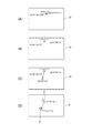
図8(A)は、表示領域Vにおいて表示制御部147が表示するポインターの表示例を示す。図8(A)の例では矢印形状のポインターPが表示され、このポインターPの表示位置が、トラックパッド14の操作に応じて移動される。   FIG. 8A shows a display example of pointers displayed by the display control unit 147 in the display area V. FIG. In the example of FIG. 8A, an arrow-shaped pointer P is displayed, and the display position of the pointer P is moved according to the operation of the track pad 14.

図8(B)はトラックパッド14における操作例を示す。この例では、トラックパッド14の位置A1で接触操作が検出され、その後、検出された位置が位置A2に移動する。操作検出制御部152は、1点操作モードを実行し、基点位置の座標として位置A1の座標(Xa1,Ya1)及び位置A2の座標(Xa2,Ya2)を取得する。操作検出制御部152は、位置A1(Xa1,Ya1)から位置A2(Xa2,Ya2)への移動を示す移動データを生成して出力する。表示制御部147は、この移動データに対応して、図8(A)に示すように、ポインターPの表示位置を、位置P1(Xp1,Yp1)から位置P2(Xp2,Yp2)に移動する。   FIG. 8B shows an operation example on the track pad 14. In this example, the contact operation is detected at the position A1 of the track pad 14, and then the detected position moves to the position A2. The operation detection control unit 152 executes the one-point operation mode, and acquires the coordinates (Xa1, Ya1) of the position A1 and the coordinates (Xa2, Ya2) of the position A2 as the coordinates of the base point position. The operation detection control unit 152 generates and outputs movement data indicating movement from the position A1 (Xa1, Ya1) to the position A2 (Xa2, Ya2). In response to the movement data, the display control unit 147 moves the display position of the pointer P from the position P1 (Xp1, Yp1) to the position P2 (Xp2, Yp2) as shown in FIG.

ここで、ポインターPの表示位置の移動量は、移動データに基づき算出される。ポインターPの表示位置のX方向の移動量(Xp2―Xp1)及びY方向の移動量(Yp2−Yp1)と、基点位置のX方向の移動量(Xa2−Xa1)及びY方向の移動量(Ya2−Ya1)とは、所定のパラメーター、関数、行列等により対応付けられる。この対応付けに関するデータは、例えば操作設定データ127に含まれる。   Here, the movement amount of the display position of the pointer P is calculated based on the movement data. A movement amount in the X direction (Xp2-Xp1) and a movement amount in the Y direction (Yp2-Yp1) of the display position of the pointer P, a movement amount in the X direction (Xa2-Xa1), and a movement amount in the Y direction (Ya2). -Ya1) is associated with a predetermined parameter, function, matrix, or the like. Data relating to this association is included in the operation setting data 127, for example.

図6に戻り、操作検出制御部152は、トラックパッド14における操作が解除されたか否かを判定する(ステップS23)。操作の解除とは、トラックパッド14に対する接触操作がなくなったことを指す。
操作が解除されていない場合(ステップS23;No)、操作検出制御部152はステップS19に戻って1点操作モードを継続する。また、操作が解除された場合(ステップS23;Yes)、制御部150は、トラックパッド14の操作の検出を終了するか否かを判定する(ステップS24)。HMD100の電源がオフされる場合、トラックパッド14の操作終了が指示された場合、トラックパッド14の操作に対応する表示の終了が指示された場合等、制御部150は、検出を終了すると判定し(ステップS24;Yes)、本処理を終了する。また、検出を終了しないと判定した場合(ステップS24;No)、制御部150は、ステップS13に戻ってトラックパッド14の操作を待機する。
Returning to FIG. 6, the operation detection control unit 152 determines whether or not the operation on the track pad 14 is released (step S23). The cancellation of the operation means that the contact operation with respect to the track pad 14 is lost.
When the operation has not been released (step S23; No), the operation detection control unit 152 returns to step S19 and continues the one-point operation mode. When the operation is released (step S23; Yes), the control unit 150 determines whether or not the detection of the operation of the track pad 14 is ended (step S24). When the power of the HMD 100 is turned off, when the operation end of the track pad 14 is instructed, or when the end of the display corresponding to the operation of the track pad 14 is instructed, the control unit 150 determines to end the detection. (Step S24; Yes), this process is terminated. If it is determined that the detection is not completed (step S24; No), the control unit 150 returns to step S13 and waits for the operation of the track pad 14.

また、操作検出制御部152は、トラックパッド14における操作位置を取得して、操作位置が1箇所でないと判定した場合(ステップS16;No、ステップS20;No)、多点操作モードを開始する(図7のステップS31)。
操作検出制御部152は、既に取得したトラックパッド14における複数の操作位置の座標から、基点位置を算出する(ステップS32)。例えば、操作検出制御部152は、トラックパッド14における全ての操作位置の座標に対し所定の演算処理を実行し、基点位置の座標を算出する。基点位置を求めるための演算式、関数、パラメーター等は、例えば、操作設定データ127に含まれる。
In addition, the operation detection control unit 152 acquires the operation position on the track pad 14 and determines that the operation position is not one (step S16; No, step S20; No), and starts the multipoint operation mode ( Step S31 in FIG.
The operation detection control unit 152 calculates a base point position from the coordinates of a plurality of operation positions on the track pad 14 that has already been acquired (step S32). For example, the operation detection control unit 152 performs a predetermined calculation process on the coordinates of all the operation positions on the track pad 14 and calculates the coordinates of the base point position. An arithmetic expression, a function, a parameter, and the like for obtaining the base point position are included in the operation setting data 127, for example.

操作検出制御部152は、トラックパッド14の操作位置を取得する(ステップS33)。ここで、操作検出制御部152は、操作位置の数が、2箇所から3箇所に増加したか否かを判定する(ステップS34)。すなわち、操作検出制御部152は、3点操作モードを開始する条件の正否を判定する。3点操作モードは、トラックパッド14で2つの位置で接触操作がされた状態で、3つめの接触操作を検出した場合に実行される。例えば、トラックパッド14の接触操作の位置が1箇所から3箇所に増えた場合や、接触操作が無い状態から3箇所の接触操作が行われた場合、3点操作モードを実行しない。操作検出制御部152は、過去に検出したトラックパッド14における操作位置の数とステップS33で取得した操作位置の数とを比較してステップS34の判定を行う。   The operation detection control unit 152 acquires the operation position of the track pad 14 (step S33). Here, the operation detection control unit 152 determines whether or not the number of operation positions has increased from two to three (step S34). That is, the operation detection control unit 152 determines whether the condition for starting the three-point operation mode is correct. The three-point operation mode is executed when the third contact operation is detected while the contact operation is performed at two positions on the track pad 14. For example, the three-point operation mode is not executed when the position of the contact operation on the track pad 14 is increased from one to three, or when three contact operations are performed from a state where there is no contact operation. The operation detection control unit 152 compares the number of operation positions on the track pad 14 detected in the past with the number of operation positions acquired in step S33, and performs the determination in step S34.

操作位置の数が2箇所から3箇所に増加した場合に該当しないと判定した場合(ステップS34;No)、操作検出制御部152は、操作位置が1箇所に減少したか否かを判定する(ステップS35)。ここで、操作位置が1箇所に減少したと判定した場合(ステップS35;Yes)、操作検出制御部152はステップS17(図6)に移行して1点操作モードを開始する。   When it is determined that the operation position does not correspond to the case where the number of operation positions is increased from 2 to 3 (step S34; No), the operation detection control unit 152 determines whether or not the operation position is decreased to one position ( Step S35). If it is determined that the operation position has decreased to one place (step S35; Yes), the operation detection control unit 152 proceeds to step S17 (FIG. 6) and starts the one-point operation mode.

操作位置が1箇所に減少していないと判定した場合(ステップS35;No)、操作検出制御部152は、例えばステップS32と同様の処理を行うことで、トラックパッド14の複数の操作位置から基点位置を算出する(ステップS36)。操作検出制御部152は、基点位置の移動量と移動方向とを示す移動データを生成して出力する(ステップS37)。表示制御部147は、操作検出制御部152が出力する移動データに基づいて、ポインターの表示位置を移動させ、表示を更新する(ステップS38)。このステップS37〜S38の処理は、ポインターの「移動表示」に相当する。   If it is determined that the operation position has not decreased to one place (step S35; No), the operation detection control unit 152 performs the same processing as in step S32, for example, so that the base point is determined from the plurality of operation positions of the track pad 14. The position is calculated (step S36). The operation detection control unit 152 generates and outputs movement data indicating the movement amount and movement direction of the base point position (step S37). The display control unit 147 moves the display position of the pointer based on the movement data output from the operation detection control unit 152, and updates the display (step S38). The processing in steps S37 to S38 corresponds to “moving display” of the pointer.

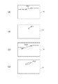
図9(A)はトラックパッド14における操作の例を示し、図9(B)はトラックパッド14の操作位置の変化の例を示す。図9(C)は操作位置の移動に対応する表示の変化を示す。
図9(A)は、トラックパッド14の複数の位置で接触操作が検出された例を示す。図9(A)では2つの位置A1(Xa1,Ya1)と位置B1(Xb1,Yb1)で操作が検出される。操作検出制御部152は、位置A1及び位置B1の座標に基づき、基点S1の座標(Xs1,Ys1)を算出する。例えば、基点S1は、位置A1と位置B1の中点とすることができる。また、トラックパッド14で3以上の位置で操作された場合、最も単純な例では、全ての操作位置の座標の平均を算出して、基点S1の座標とすることができる。また、多点操作モードにおいて、基点S1は、操作位置(ここではA1、B1)とは異なる位置に設定される。
FIG. 9A shows an example of operation on the track pad 14, and FIG. 9B shows an example of change in the operation position of the track pad 14. FIG. 9C shows a change in display corresponding to the movement of the operation position.
FIG. 9A shows an example in which contact operations are detected at a plurality of positions on the track pad 14. In FIG. 9A, an operation is detected at two positions A1 (Xa1, Ya1) and B1 (Xb1, Yb1). The operation detection control unit 152 calculates the coordinates (Xs1, Ys1) of the base point S1 based on the coordinates of the position A1 and the position B1. For example, the base point S1 can be a midpoint between the position A1 and the position B1. Further, in the simplest example, when the track pad 14 is operated at three or more positions, the average of the coordinates of all the operation positions can be calculated and used as the coordinates of the base point S1. In the multipoint operation mode, the base point S1 is set at a position different from the operation position (A1, B1 here).

図9(B)はトラックパッド14の複数の位置で接触操作が検出され、これら複数の操作位置が移動した例を示す。図9(B)の例では、操作位置A1が位置A2(Xa2,Ya2)に移動し、操作位置B1がB2(Xb2,Yb2)に移動している。この場合、基点S1は、位置S2(Xs2,Ys2)に移動する。この場合、操作検出制御部152は、基点の位置S1(Xs1,Ys1)から位置S2(Xs2,Ys2)への移動を示す移動データを生成して出力する。すなわち、基点の座標のX方向の移動量(Xs2−Xs1)及びY方向の移動量(Ys2−Ys1)を示す移動データを出力する。表示制御部147は、この移動データに対応して、図9(C)に示すように、ポインターPの表示位置を、位置P1(Xp1,Yp1)から位置P2(Xp2,Yp2)に移動する。   FIG. 9B shows an example in which contact operations are detected at a plurality of positions on the track pad 14 and the plurality of operation positions are moved. In the example of FIG. 9B, the operation position A1 has moved to position A2 (Xa2, Ya2), and the operation position B1 has moved to B2 (Xb2, Yb2). In this case, the base point S1 moves to the position S2 (Xs2, Ys2). In this case, the operation detection control unit 152 generates and outputs movement data indicating movement from the base position S1 (Xs1, Ys1) to the position S2 (Xs2, Ys2). That is, movement data indicating the movement amount in the X direction (Xs2-Xs1) and the movement amount in the Y direction (Ys2-Ys1) of the coordinates of the base point is output. In response to the movement data, the display control unit 147 moves the display position of the pointer P from the position P1 (Xp1, Yp1) to the position P2 (Xp2, Yp2) as shown in FIG. 9C.

ポインターPの表示位置の移動量は、移動データに基づき算出される。上述したように、ポインターPの表示位置のX方向の移動量(Xp1―Xp2)及びY方向の移動量(Yp2−Yp1)と、基点位置のX方向の移動量及びY方向の移動量との対応は、所定のパラメーター、関数、或いは行列等により対応付けられる。この対応付けに関するデータは、例えば操作設定データ127に含まれる。   The amount of movement of the display position of the pointer P is calculated based on the movement data. As described above, the movement amount in the X direction (Xp1-Xp2) and the movement amount in the Y direction (Yp2-Yp1) of the display position of the pointer P and the movement amount in the X direction and the movement amount in the Y direction of the base point position The correspondence is associated with a predetermined parameter, function, matrix, or the like. Data relating to this association is included in the operation setting data 127, for example.

図7に戻り、操作検出制御部152は、トラックパッド14における操作が解除されたか否かを判定する(ステップS39)。操作が解除されていない場合(ステップS39;No)、操作検出制御部152はステップS33に戻って多点操作モードを継続する。操作が解除された場合(ステップS39;Yes)、制御部150は、ステップS24(図6)に移行する。   Returning to FIG. 7, the operation detection control unit 152 determines whether or not the operation on the track pad 14 has been released (step S39). If the operation is not released (step S39; No), the operation detection control unit 152 returns to step S33 and continues the multipoint operation mode. When the operation is released (step S39; Yes), the control unit 150 proceeds to step S24 (FIG. 6).

また、3点操作モードを開始する条件が成立したと判定した場合(ステップS34;Yes)、操作検出制御部152は、3点操作モードを開始する(ステップS41)。3点操作モードでは、3番目の操作位置、すなわち、2つの操作位置が検出された状態において新たに(最後に)検出された操作位置を、基点に対応付ける(ステップS42)。   When it is determined that the condition for starting the three-point operation mode is satisfied (step S34; Yes), the operation detection control unit 152 starts the three-point operation mode (step S41). In the three-point operation mode, the third operation position, that is, the operation position newly (finally) detected in the state where the two operation positions are detected is associated with the base point (step S42).

操作検出制御部152は、トラックパッド14の操作位置を取得する(ステップS43)。ここで、操作検出制御部152は、操作位置の数が3箇所であるか否かを判定する(ステップS44)。操作位置が3箇所でない場合(ステップS44;No)、操作位置の増減があったことになるので、操作検出制御部152は、ステップS16(図6)に移行する。また、操作位置が3箇所である場合(ステップS44;Yes)、操作検出制御部152は3点操作モードを継続し、基点位置の移動データを出力する(ステップS45)。ステップS45で、操作検出制御部152は、トラックパッド14の検出領域における3番目の操作位置の座標を基点の座標として、移動データを生成して出力する。
表示制御部147は、操作検出制御部152が出力する移動データに基づき、ポインターの表示位置を移動させる(ステップS46)。このステップS45〜S46の処理は、ポインターの「移動表示」に相当する。
The operation detection control unit 152 acquires the operation position of the track pad 14 (step S43). Here, the operation detection control unit 152 determines whether or not the number of operation positions is three (step S44). If the operation position is not three (step S44; No), the operation position has increased or decreased, and the operation detection control unit 152 proceeds to step S16 (FIG. 6). If there are three operation positions (step S44; Yes), the operation detection control unit 152 continues the three-point operation mode and outputs movement data of the base point position (step S45). In step S45, the operation detection control unit 152 generates and outputs movement data using the coordinates of the third operation position in the detection area of the track pad 14 as the coordinates of the base point.
The display control unit 147 moves the display position of the pointer based on the movement data output from the operation detection control unit 152 (step S46). The processing in steps S45 to S46 corresponds to “moving display” of the pointer.

図10(A)はトラックパッド14における操作の例を示し、図10(B)はトラックパッド14の操作位置の変化の例を示す。図10(C)は操作位置の移動の例を示し、図10(D)は操作位置の移動に対応する表示の変化を示す。   FIG. 10A shows an example of an operation on the track pad 14, and FIG. 10B shows an example of a change in the operation position of the track pad 14. FIG. 10C shows an example of movement of the operation position, and FIG. 10D shows a change in display corresponding to the movement of the operation position.

図10(A)は、トラックパッド14の複数の位置で接触操作が検出された例として、2つの位置A1(Xa1,Ya1)と位置B1(Xb1,Yb1)で操作が検出された例を示す。図10(A)の状態で、操作検出制御部152は、多点操作モードを実行し、位置A1及び位置B1の座標に基づき、基点S1の座標(Xs1,Ys1)を算出する。   FIG. 10A shows an example in which operations are detected at two positions A1 (Xa1, Ya1) and B1 (Xb1, Yb1) as examples in which contact operations are detected at a plurality of positions on the track pad 14. . In the state of FIG. 10A, the operation detection control unit 152 executes the multipoint operation mode, and calculates the coordinates (Xs1, Ys1) of the base point S1 based on the coordinates of the position A1 and the position B1.

図10(B)に示すように、図10(A)の状態から3番目の操作位置C1(Xc1,Yc1)の操作が検出された場合、操作検出制御部152は3点操作モードを開始する。この場合、位置C1の座標(Xc1,Yc1)が基点の座標とされる。
図10(C)に示すように、位置C1が位置C2(Xc2,Yc2)に移動した場合、操作検出制御部152は、X方向の移動量(Xc2−Xc1)及びY方向の移動量(Yc2−Yc1)に対応する移動データを出力する。図10(C)の例では先に検出された操作位置A1、A2は移動していないが、これらの操作位置は、基点の位置を求める処理に関与しない。
表示制御部147は、移動データに対応して、図10(D)に示すように、ポインターPの表示位置を、位置P1(Xp1,Yp1)から位置P2(Xp2,Yp2)に移動する。
As shown in FIG. 10B, when the operation at the third operation position C1 (Xc1, Yc1) is detected from the state of FIG. 10A, the operation detection control unit 152 starts the three-point operation mode. . In this case, the coordinates (Xc1, Yc1) of the position C1 are the coordinates of the base point.
As shown in FIG. 10C, when the position C1 moves to the position C2 (Xc2, Yc2), the operation detection control unit 152 moves the X direction (Xc2-Xc1) and the Y direction (Yc2). The movement data corresponding to -Yc1) is output. In the example of FIG. 10C, the previously detected operation positions A1 and A2 are not moved, but these operation positions are not involved in the processing for obtaining the position of the base point.
In response to the movement data, the display control unit 147 moves the display position of the pointer P from the position P1 (Xp1, Yp1) to the position P2 (Xp2, Yp2) as shown in FIG.

図10(B)及び(C)の操作は、例えば、使用者が片手の3本の指を使って行うことができる。使用者が2本の指でトラックパッド14にタッチした状態で、3本目の指をタッチした場合、この3本目の指の位置が基点の位置とされ、3本目の指の移動に応じてポインターPが移動される。つまり、使用者は、2本の指のタッチ操作によりポインターPの表示位置を移動させ、さらに、これら2本の指を動かさなくても、3本目の指でタッチ操作を行うことで、ポインターPを移動させることができる。例えば、2本の指のタッチ操作中に、これら2本の指が検出領域の端に達したり、使用者の姿勢の都合で2本の指を動かしにくくなったりした場合、3本目の指でタッチ操作を行うことで、ポインターPを移動させることができる。   The operations shown in FIGS. 10B and 10C can be performed by the user using, for example, three fingers of one hand. When the user touches the trackpad 14 with two fingers and touches the third finger, the position of the third finger is the base point, and the pointer is moved according to the movement of the third finger. P is moved. That is, the user moves the display position of the pointer P by a touch operation with two fingers, and further performs the touch operation with the third finger without moving the two fingers, thereby the pointer P. Can be moved. For example, if the two fingers reach the end of the detection area during the touch operation of two fingers, or if it becomes difficult to move the two fingers due to the user's posture, the third finger The pointer P can be moved by performing a touch operation.

このように、3点操作モードを利用することで、特有の操作性を実現できる。また、操作検出制御部152は、上述したステップS34の条件を満たした場合にのみ3点操作モードを開始するので、誤って3点操作モードを開始してしまう可能性は極めて低く、誤操作を防止できる。   In this way, by using the three-point operation mode, a specific operability can be realized. In addition, since the operation detection control unit 152 starts the three-point operation mode only when the above-described condition of step S34 is satisfied, the possibility of erroneously starting the three-point operation mode is extremely low, and erroneous operation is prevented. it can.

図7に戻り、操作検出制御部152は、トラックパッド14における操作が解除されたか否かを判定する(ステップS47)。操作が解除されていない場合(ステップS47;No)、操作検出制御部152はステップS43に戻って3点操作モードを継続する。操作が解除された場合(ステップS47;Yes)、制御部150は、ステップS24(図6)に移行する。   Returning to FIG. 7, the operation detection control unit 152 determines whether or not the operation on the track pad 14 is released (step S47). If the operation has not been released (step S47; No), the operation detection control unit 152 returns to step S43 and continues the three-point operation mode. When the operation is released (step S47; Yes), the control unit 150 proceeds to step S24 (FIG. 6).

図6〜図10を参照して説明した例では、表示制御部147がポインターPを表示し、このポインターPの表示位置を変更する動作を説明した。操作検出制御部152及び表示制御部147の機能はこれに限定されない。例えば、表示制御部147は、操作検出制御部152が出力する移動データに基づき、画像表示部20の表示領域に表示する画面の一部または全体をスクロールさせる動作を行ってもよい。この場合、表示制御部147は、移動データに含まれる基点の移動方向に対応してスクロール方向を決定し、基点の移動量に対応してスクロール量を決定すればよい。また、例えば、表示制御部147は、操作検出制御部152が出力する移動データに基づき、画像表示部20の表示領域に表示する画面の一部または全体を拡大/縮小させるズーム動作を行ってもよい。この場合、表示制御部147は、移動データに含まれる基点の移動方向に対応してズームの方向すなわち拡大か縮小かを決定し、基点の移動量に対応してズーム量を決定すればよい。この場合の拡大/縮小の中心は、例えば、基点位置に対応する表示位置としてもよい。   In the example described with reference to FIGS. 6 to 10, the operation in which the display control unit 147 displays the pointer P and changes the display position of the pointer P has been described. The functions of the operation detection control unit 152 and the display control unit 147 are not limited to this. For example, the display control unit 147 may perform an operation of scrolling part or all of the screen displayed in the display area of the image display unit 20 based on the movement data output from the operation detection control unit 152. In this case, the display control unit 147 may determine the scroll direction corresponding to the movement direction of the base point included in the movement data, and determine the scroll amount corresponding to the movement amount of the base point. Further, for example, the display control unit 147 may perform a zoom operation for enlarging / reducing a part or the whole of the screen displayed in the display area of the image display unit 20 based on the movement data output from the operation detection control unit 152. Good. In this case, the display control unit 147 may determine the zoom direction corresponding to the movement direction of the base point included in the movement data, that is, enlargement or reduction, and determine the zoom amount corresponding to the movement amount of the base point. In this case, the center of enlargement / reduction may be, for example, a display position corresponding to the base position.

また、表示制御部147は、図7の多点操作モードにおいて、操作位置と操作位置との間隔が大きくなる操作、或いは、間隔が小さくなる操作を検出した場合、ポインターPを中心とした拡大、縮小を行ってもよい。この動作は、いわゆるピンチ操作(ピンチイン、ピンチアウト)に相当する。この場合、ポインターPの表示位置の移動を停止してもよいし、ポインターPの表示を停止してもよい。   In addition, in the multipoint operation mode of FIG. 7, when the display control unit 147 detects an operation in which the interval between the operation positions becomes large or an operation in which the interval becomes small, Reduction may be performed. This operation corresponds to a so-called pinch operation (pinch-in, pinch-out). In this case, the movement of the display position of the pointer P may be stopped, or the display of the pointer P may be stopped.

また、表示制御部147は、ポインターPの形状等を変更してもよい。
図11は、HMD100における表示の別の例を示す図である。図11(A)はトラックパッド14において複数の操作位置における操作を検出した場合の表示例を示す。また、図11(B)、図11(C)は複数の操作位置の移動の様子を示し、図11(D)は操作位置の移動に対応する表示の変化を示す。
Further, the display control unit 147 may change the shape or the like of the pointer P.
FIG. 11 is a diagram illustrating another example of display in the HMD 100. FIG. 11A shows a display example when operations at a plurality of operation positions on the track pad 14 are detected. FIGS. 11B and 11C show the movement of a plurality of operation positions, and FIG. 11D shows a change in display corresponding to the movement of the operation positions.

図11(A)の例で、ポインターPを表示した状態で操作検出制御部152により複数の操作位置が検出されると、表示制御部147はポインターPの表示を停止し、代わりに2つの操作位置に対応するマーカーQ1、Q2を表示する。
さらに、操作検出制御部152は、図11(B)に示すように、2つの操作位置A1(Xa1,Ya1)、位置B1(Xb1,Yb1)に基づき、基点S1の座標(Xs1,Ys1)を算出する。
In the example of FIG. 11A, when the operation detection control unit 152 detects a plurality of operation positions while the pointer P is displayed, the display control unit 147 stops the display of the pointer P, and two operations are performed instead. Markers Q1 and Q2 corresponding to the positions are displayed.
Further, as shown in FIG. 11B, the operation detection control unit 152 determines the coordinates (Xs1, Ys1) of the base point S1 based on the two operation positions A1 (Xa1, Ya1) and the position B1 (Xb1, Yb1). calculate.

その後、操作位置が移動すると、操作検出制御部152は、図11(C)に示すように、2つの操作位置A1、B1が移動した移動後の位置A2、B2の座標に基づき、移動後の基点S2の座標(Xs2,Ys2)を算出する。そして、操作検出制御部152は、基点S1からS2への移動に対応する移動データを出力する。   After that, when the operation position is moved, the operation detection control unit 152, as shown in FIG. 11C, is based on the coordinates of the moved positions A2 and B2 where the two operation positions A1 and B1 are moved. The coordinates (Xs2, Ys2) of the base point S2 are calculated. Then, the operation detection control unit 152 outputs movement data corresponding to the movement from the base point S1 to S2.

表示制御部147は、図11(D)に示すように、操作検出制御部152が出力する移動データに対応して、マーカーQ1、Q2の表示位置を移動する。この場合、マーカーQ1、Q2の移動方向及び移動量は、基点S1−S2の移動量に対応する。より詳細には、マーカーQ1が位置PA1から位置PA2に移動するX方向の移動量(XPa2−XPa1)及びY方向の移動量(YPa2−YPa1)は、基点のX方向の移動量(Xs2−Xs1)及びY方向の移動量(Ys2−Ys1)に対応する。マーカーQ2の位置PB1から位置PB2への移動も同様である。
このように、ポインターPの表示を、トラックパッド14へのタッチ操作の数に応じてマーカーQ1、Q2に変更することにより、トラックパッド14で検出したタッチ操作の数を使用者に知らせることができる。このため、使用者は、トラックパッド14を視認しなくても、トラックパッド14に対する操作の状態を知ることができる。
As shown in FIG. 11D, the display control unit 147 moves the display positions of the markers Q1 and Q2 in accordance with the movement data output from the operation detection control unit 152. In this case, the movement direction and movement amount of the markers Q1, Q2 correspond to the movement amount of the base points S1-S2. More specifically, the movement amount in the X direction (XPa2-XPa1) and the movement amount in the Y direction (YPa2-YPa1) by which the marker Q1 moves from the position PA1 to the position PA2 are the movement amount in the X direction of the base point (Xs2-Xs1). ) And the amount of movement in the Y direction (Ys2-Ys1). The movement of the marker Q2 from the position PB1 to the position PB2 is the same.
Thus, by changing the display of the pointer P to the markers Q1 and Q2 according to the number of touch operations on the track pad 14, the user can be notified of the number of touch operations detected by the track pad 14. . For this reason, the user can know the state of operation with respect to the track pad 14 without visually recognizing the track pad 14.

本実施形態では、制御部150の制御により、HMD100は、所定画像としてポインターP、及びマーカーQ1、Q2を表示する。所定画像はポインターP、及びマーカーQ1、Q2に限定されず、表示領域に描かれる円形で構成されるサークルポインターまたは「○」形状のポインターであってもよい。また、十字形状のポインターとしてもよい。   In the present embodiment, under the control of the control unit 150, the HMD 100 displays a pointer P and markers Q1 and Q2 as predetermined images. The predetermined image is not limited to the pointer P and the markers Q1 and Q2, and may be a circle pointer configured by a circle drawn in the display area or a “◯” shaped pointer. Also, a cross-shaped pointer may be used.

また、上記実施形態では、トラックパッド14における2つの操作位置に対応してマーカーQ1、Q2を表示する例、3つの操作位置に対応してポインターPを表示する例を説明した。ここで、2以上の操作位置に対応して所定画像としてマーカーQ1、Q2或いはポインターPを表示する場合に、所定画像の表示態様を変化させてもよい。例えば、トラックパッド14で検出する複数の検出位置間の距離に対応して、所定画像の透過率(明るさ)を変化させることが考えられる。画像表示部20では、右表示ユニット22及び左表示ユニット24が画像を表示する輝度を高くするほど、外光OL(図2)に対する画像光Lの相対的な光量が高くなるため、表示画像の視認性が高まる。つまり、画像表示部20の表示画像の透過率が低くなる。これに対し、右表示ユニット22及び左表示ユニット24が画像を表示する輝度を低くするほど、外光OLに対する画像光Lの相対的な光量が低くなるので、表示画像の視認性が低くなる。つまり、画像表示部20の表示画像の透過率が高くなる。例えば、制御部150の制御によって、トラックパッド14で検出される複数の検出位置の間の距離が小さいほど、画像表示部20が表示する所定画像の明るさを高くすることが考えられる。別の表現では、制御部150は、操作位置の間隔が狭いほど所定画像の輝度を高くし、これにより透過率が低くなる。これにより、位置を細かく調整する操作が行われる場合にポインターPやマーカーQ1、Q2の視認性を高めることで、操作性の向上を図ることができる。反対に、トラックパッド14で検出される複数の検出位置の間の距離が大きいほど、画像表示部20が表示する所定画像の明るさを低くすることが考えられる。別の表現では、制御部150は、操作位置の間隔が大きいほど所定画像の輝度を低くし、これにより透過率が高くなる。外景を透過して視認可能に画像を表示する画像表示部20では、表示画像の透過率は視認性および操作性への影響が強く、見やすさの指標として考えることができる。このため、操作の細かさに対応して表示画像であるポインターやマーカーの透過率を変更することにより、操作性を大きく向上させることができる。また、制御部150は、トラックパッド14で検出する操作位置の数が1の場合、操作位置が2の場合、3以上の場合について、ポインターPやマーカーQ1、Q2を変更してもよい。この場合、使用者は、ポインターPやマーカーQ1、Q2の透過率によって、トラックパッド14で検出された操作位置の数を知ることができる。また、使用者がトラックパッド14に対して行う操作の態様に対応して、ポインターPやマーカーQ1、Q2の表示態様としての透過率を変化させることで、操作性のより一層の向上を図ることができる。   In the above embodiment, the example in which the markers Q1 and Q2 are displayed corresponding to the two operation positions on the track pad 14 and the pointer P is displayed in correspondence with the three operation positions has been described. Here, when displaying the markers Q1, Q2 or the pointer P as a predetermined image corresponding to two or more operation positions, the display mode of the predetermined image may be changed. For example, it is conceivable to change the transmittance (brightness) of a predetermined image in accordance with the distance between a plurality of detection positions detected by the track pad 14. In the image display unit 20, the higher the luminance at which the right display unit 22 and the left display unit 24 display an image, the higher the relative light quantity of the image light L with respect to the external light OL (FIG. 2). Visibility is increased. That is, the transmittance of the display image of the image display unit 20 is lowered. On the other hand, the lower the luminance at which the right display unit 22 and the left display unit 24 display an image, the lower the relative light quantity of the image light L with respect to the external light OL, and the lower the visibility of the display image. That is, the transmittance of the display image of the image display unit 20 is increased. For example, under the control of the control unit 150, it is conceivable that the brightness of a predetermined image displayed by the image display unit 20 is increased as the distance between a plurality of detection positions detected by the track pad 14 is smaller. In another expression, the control unit 150 increases the luminance of the predetermined image as the operation position interval is narrower, and thereby decreases the transmittance. Thereby, when an operation for finely adjusting the position is performed, the operability can be improved by increasing the visibility of the pointer P and the markers Q1 and Q2. On the contrary, it is conceivable that the brightness of the predetermined image displayed by the image display unit 20 is lowered as the distance between the plurality of detection positions detected by the track pad 14 is larger. In another expression, the control unit 150 decreases the brightness of the predetermined image as the interval between the operation positions is larger, thereby increasing the transmittance. In the image display unit 20 that displays an image so as to be visible through the outside scene, the transmittance of the display image has a strong influence on the visibility and operability, and can be considered as an index of visibility. For this reason, the operability can be greatly improved by changing the transmittance of the pointer or marker which is a display image corresponding to the fineness of the operation. Further, the control unit 150 may change the pointer P and the markers Q1 and Q2 when the number of operation positions detected by the track pad 14 is 1, when the operation position is 2, and when the number is 3 or more. In this case, the user can know the number of operation positions detected by the track pad 14 from the transmittance of the pointer P and the markers Q1 and Q2. Further, the operability can be further improved by changing the transmittance as the display mode of the pointer P and the markers Q1 and Q2 corresponding to the mode of operation performed by the user on the track pad 14. Can do.

また、例えば、制御部150の制御によって、トラックパッド14で検出される複数の検出位置の間の距離に対応して、所定画像の形状を変化させてもよい。この場合について図12及び図13に例を示す。   Further, for example, the shape of the predetermined image may be changed according to the distance between a plurality of detection positions detected by the track pad 14 under the control of the control unit 150. An example of this case is shown in FIGS.

図12は、HMD100の操作に対応する表示の変化を示す説明図である。図12(A)はトラックパッド14における操作位置の例を示し、図12(B)は画像表示部20が表示するポインターP11を示す。図12(C)はトラックパッド14における操作位置の例を示し、図12(B)は画像表示部20が表示するポインターP12を示す。   FIG. 12 is an explanatory diagram showing a change in display corresponding to the operation of the HMD 100. 12A shows an example of the operation position on the track pad 14, and FIG. 12B shows a pointer P11 displayed by the image display unit 20. FIG. 12C shows an example of the operation position on the track pad 14, and FIG. 12B shows a pointer P 12 displayed on the image display unit 20.

図12(A)は制御部150が、トラックパッド14で2つの操作位置A1(Xa1,Ya1)とB1(Xb1,Yb1)を検出した例を示す。図12(B)は、図12(A)の操作位置に対応して、例えば2点の中央の操作位置に対応する表示位置に、円形のポインターP11を表示する例を示す。
制御部150が、トラックパッド14における操作位置の間隔が大きくなるほど、ポインターの形状を細長くする制御を行う場合、図12(D)に示すように、楕円形のポインターP12を表示する。つまり、図12(C)に示すように、制御部150が、トラックパッド14で2つの操作位置A1(Xa1,Ya1)とB3(Xb3,Yb3)を検出し、位置A1−B3間の距離Dis2が、位置A1−B1間の距離Dis1より長い場合を想定する。この場合、制御部150は、距離Dis3に対応する楕円率の楕円形であるポインターP12を、操作位置A1(Xa1,Ya1)とB3(Xb3,Yb3)との中点に対応する表示位置に表示する。
FIG. 12A shows an example in which the control unit 150 detects two operation positions A1 (Xa1, Ya1) and B1 (Xb1, Yb1) with the trackpad 14. FIG. 12B shows an example in which a circular pointer P11 is displayed at a display position corresponding to the operation position at the center of two points, for example, corresponding to the operation position of FIG.
When the control unit 150 performs control to make the shape of the pointer elongated as the interval between the operation positions on the track pad 14 increases, an elliptical pointer P12 is displayed as shown in FIG. That is, as shown in FIG. 12C, the control unit 150 detects two operation positions A1 (Xa1, Ya1) and B3 (Xb3, Yb3) with the track pad 14, and a distance Dis2 between the positions A1 and B3. Is longer than the distance Dis1 between the positions A1 and B1. In this case, the control unit 150 displays the pointer P12 having an ellipticity corresponding to the distance Dis3 at a display position corresponding to the midpoint between the operation positions A1 (Xa1, Ya1) and B3 (Xb3, Yb3). To do.

図13は、HMD100の操作に対応する表示の変化を示す説明図である。図13(A)はトラックパッド14における操作位置の例を示し、図13(B)は画像表示部20が表示するポインターP21を示す。図13(C)はトラックパッド14における操作位置の例を示し、図13(B)は画像表示部20が表示するポインターP22を示す。
図13の例では十字形状のポインターP21、P22を表示する例を示す。
FIG. 13 is an explanatory diagram showing a change in display corresponding to the operation of the HMD 100. FIG. 13A shows an example of an operation position on the track pad 14, and FIG. 13B shows a pointer P 21 displayed on the image display unit 20. FIG. 13C shows an example of the operation position on the track pad 14, and FIG. 13B shows a pointer P 22 displayed on the image display unit 20.
The example of FIG. 13 shows an example in which cross-shaped pointers P21 and P22 are displayed.

図13(A)は制御部150が、トラックパッド14で2つの操作位置A1(Xa1,Ya1)とB1(Xb1,Yb1)を検出した例を示す。図13(B)は、図13(A)の操作位置に対応して、例えば2点の中央の操作位置に対応する表示位置に、十字形状のポインターP21を表示する例を示す。   FIG. 13A shows an example in which the control unit 150 detects two operation positions A1 (Xa1, Ya1) and B1 (Xb1, Yb1) with the trackpad 14. FIG. 13B shows an example in which a cross-shaped pointer P21 is displayed at a display position corresponding to the operation position at the center of two points, for example, corresponding to the operation position of FIG.

制御部150が、トラックパッド14における操作位置の間隔が大きくなるほど、ポインターの形状を細長くする制御を行う場合、図13(D)に示すように、十字形状を細長く延長したポインターP22を表示する。図13(C)に示すように、制御部150が、トラックパッド14で2つの操作位置A1(Xa1,Ya1)とB3(Xb3,Yb3)を検出し、位置A1−B3間の距離Dis2が、位置A1−B1間の距離Dis1より長い場合を想定する。この場合、制御部150は、距離Dis2に対応して、横方向の直線が延長されたポインターP22を、操作位置A1(Xa1,Ya1)とB3(Xb3,Yb3)との中点に対応する表示位置に表示する。   When the control unit 150 performs control to elongate the shape of the pointer as the interval between the operation positions on the track pad 14 increases, the pointer P22 obtained by extending the cross shape to be elongated is displayed as shown in FIG. As shown in FIG. 13C, the control unit 150 detects two operation positions A1 (Xa1, Ya1) and B3 (Xb3, Yb3) with the track pad 14, and the distance Dis2 between the positions A1 and B3 is Assume that the distance between the positions A1 and B1 is longer than the distance Dis1. In this case, the control unit 150 displays the pointer P22 whose horizontal straight line is extended corresponding to the distance Dis2, corresponding to the midpoint between the operation positions A1 (Xa1, Ya1) and B3 (Xb3, Yb3). Display in position.

このように、制御部150は、図12(D)及び図13(D)に示すように、ポインターのサイズを変更してもよい。使用者の視野に影響する頭部装着型の画像表示部20では、表示画像のサイズは視認性および操作性への影響が強く、見やすさの指標として考えることができる。このため、操作の細かさに対応して表示画像であるポインターやマーカーのサイズや形状を変更することにより、操作性を大きく向上させることができる。   As described above, the control unit 150 may change the size of the pointer as illustrated in FIGS. 12D and 13D. In the head-mounted image display unit 20 that affects the user's visual field, the size of the display image has a strong influence on the visibility and operability, and can be considered as an easy-to-see index. For this reason, operability can be greatly improved by changing the size and shape of the pointers and markers, which are display images, corresponding to the fineness of the operation.

図14は、HMD100の操作に対応する表示の変化を示す説明図である。
図14(A)は、制御部150が、トラックパッド14で2つの操作位置A1(Xa1,Ya1)とB1(Xb1,Yb1)を検出した例を示す。この例では、操作位置A1が位置A2(Xa2,Ya2)に移動し、操作位置B1がB2(Xb2,Yb2)に移動する。この場合、制御部150は、上述したように、基点S1を位置A1、B1の中点に設定するので、基点S1が基点S2に移動した軌跡に対応してポインターやマーカーが表示される。
FIG. 14 is an explanatory diagram showing a change in display corresponding to the operation of the HMD 100.
FIG. 14A shows an example in which the control unit 150 detects two operation positions A1 (Xa1, Ya1) and B1 (Xb1, Yb1) with the trackpad 14. In this example, the operation position A1 moves to position A2 (Xa2, Ya2), and the operation position B1 moves to B2 (Xb2, Yb2). In this case, as described above, since the control unit 150 sets the base point S1 as the midpoint of the positions A1 and B1, pointers and markers are displayed corresponding to the trajectory where the base point S1 has moved to the base point S2.

図14(B)では、円形のポインターP31の表示位置を、基点の移動に対応して移動させる場合の表示態様の一例を示す。図14(B)に示すように、円形のポインターP31を移動させる場合、ポインターP31の移動方向や移動の軌跡が分かりやすくなるように、ポインターP31の残像を模した画像を表示してもよい。つまり、ポインターP31は、移動の軌跡を表す残像部分を含む形状となる。いわば彗星の尾のような形状となり、ポインターP31の移動の様子を使用者が明確に知ることができる。この種のポインターの形状を、軌跡または残像を有する形状に変更する処理は、ポインターの形状が矢印形状、十字形状、円形等、様々な形状である場合に適用できる。   FIG. 14B shows an example of a display mode when the display position of the circular pointer P31 is moved in accordance with the movement of the base point. As shown in FIG. 14B, when the circular pointer P31 is moved, an image imitating the afterimage of the pointer P31 may be displayed so that the moving direction and movement locus of the pointer P31 can be easily understood. That is, the pointer P31 has a shape including an afterimage portion that represents a movement locus. In other words, the shape is like a comet tail, and the user can clearly know the movement of the pointer P31. The process of changing the shape of this type of pointer to a shape having a locus or an afterimage can be applied when the pointer has various shapes such as an arrow shape, a cross shape, and a circular shape.

また、制御部150は、トラックパッド14において2つの検出位置を検出した場合、すなわち使用者が2つの位置で接触する操作を行った場合、これら2つの検出位置間の距離に応じて、ユーザーインターフェイスを変更してもよい。例えば、制御部150は、2つの検出位置間の距離を、予め設定された閾値に基づき、2段階に区別する。一例として、2つの検出位置間の距離が通常の範囲である“通常選択状態”と、2つの検出位置間の距離が小さい“精密選択状態”とに区別する。この場合、制御部150は、トラックパッド14における位置検出の解像度を、“精密選択状態”では、“通常選択状態”よりも高解像度に切り替えてもよい。   In addition, when the controller 150 detects two detection positions on the track pad 14, that is, when the user performs an operation of touching the two positions, the user interface is changed according to the distance between the two detection positions. May be changed. For example, the control unit 150 distinguishes the distance between two detection positions in two stages based on a preset threshold value. As an example, a distinction is made between a “normal selection state” in which the distance between two detection positions is a normal range and a “precise selection state” in which the distance between the two detection positions is small. In this case, the control unit 150 may switch the position detection resolution on the track pad 14 to a higher resolution in the “precision selection state” than in the “normal selection state”.

また、制御部150は、トラックパッド14における3つの操作位置を検出した場合に、これら3つの操作位置に基づき1つの基点の座標を求め、基点の座標に対応する表示位置に所定画像を表示してもよい。この場合、2つの操作位置の中央を求めて基点とし、求めた基点を、3つ目の操作位置に合わせて偏った位置にしてもよい。或いは、3つの操作位置の中心または重心に相当する位置を、基点としてもよい。   Further, when the control unit 150 detects three operation positions on the track pad 14, the control unit 150 obtains the coordinates of one base point based on the three operation positions, and displays a predetermined image at the display position corresponding to the base point coordinates. May be. In this case, the center of the two operation positions may be obtained as a base point, and the obtained base point may be set to a position that is biased according to the third operation position. Alternatively, a position corresponding to the center or the center of gravity of the three operation positions may be used as the base point.

以上説明したように、使用者が装着して使用するHMD100は、接触操作を受け付けるトラックパッド14と、画像を表示する表示領域を有する画像表示部20とを備える。また、トラックパッド14における操作位置を検出し、検出した操作に応じて画像表示部20の表示を制御する制御部150を備える。制御部150は、画像表示部20により所定画像としてのポインターやマーカーを表示し、所定画像の表示位置をトラックパッド14の操作位置に応じて移動させる。制御部150は、所定画像としてのポインターやマーカーの表示位置を移動させる際に、トラックパッド14で1つの操作位置を検出した場合と、複数の操作位置を検出した場合とで、操作位置と所定画像の表示位置との対応付けを変更する。
例えば、操作検出制御部152は、トラックパッド14において検出した操作位置の座標と基点との対応付けを、操作位置の数により変更する。1点操作モードでは操作位置を基点の位置とし、多点操作モードでは操作位置から算出される操作位置以外の位置を基点の位置とする。また、3点操作モードでは3番目の操作位置を基点の位置とする。
As described above, the HMD 100 worn and used by the user includes the track pad 14 that receives a touch operation and the image display unit 20 that has a display area for displaying an image. Moreover, the control part 150 which detects the operation position in the trackpad 14 and controls the display of the image display part 20 according to the detected operation is provided. The control unit 150 displays a pointer or marker as a predetermined image on the image display unit 20 and moves the display position of the predetermined image according to the operation position of the track pad 14. When moving the display position of the pointer or marker as the predetermined image, the control unit 150 detects the operation position and the predetermined position when detecting one operation position with the track pad 14 and when detecting a plurality of operation positions. The association with the display position of the image is changed.
For example, the operation detection control unit 152 changes the association between the coordinates of the operation position detected on the track pad 14 and the base point according to the number of operation positions. In the one-point operation mode, the operation position is set as the base point position, and in the multi-point operation mode, a position other than the operation position calculated from the operation position is set as the base point position. In the three-point operation mode, the third operation position is set as the base point position.

また、HMD100は、接触操作を受け付けるトラックパッド14と、画像を表示する表示領域を有する画像表示部20とを備える。また、トラックパッド14における操作位置を検出し、検出した操作位置に基づき表示制御用の位置を出力し、この表示制御用の位置に基づき画像を画像表示部20に表示させる制御部150を備える。制御部150は、1つの操作位置を検出した場合と、複数の操作位置を検出した場合とで、検出した操作位置と表示制御用の位置との対応付けを変更する。   The HMD 100 also includes a track pad 14 that accepts a contact operation, and an image display unit 20 that has a display area for displaying an image. In addition, a control unit 150 that detects an operation position on the track pad 14, outputs a display control position based on the detected operation position, and causes the image display unit 20 to display an image based on the display control position is provided. The control unit 150 changes the association between the detected operation position and the display control position when one operation position is detected and when a plurality of operation positions are detected.

この入力装置としての制御装置10、表示装置としてのHMD100、及び、HMD100が実行する表示装置の制御方法によれば、操作位置の数を変化させることで操作のバリエーションを増やすことができ、操作性の向上を図ることができる。
例えば、トラックパッド14に対して接触操作を行う操作位置の数によって、操作に対応するポインターの表示位置の制御の態様を変化させることができる。
According to the control device 10 as the input device, the HMD 100 as the display device, and the display device control method executed by the HMD 100, it is possible to increase the number of operation variations by changing the number of operation positions. Can be improved.
For example, the manner of controlling the display position of the pointer corresponding to the operation can be changed depending on the number of operation positions where the touch operation is performed on the track pad 14.

制御部150は、所定画像としてのポインターやマーカーの表示位置を移動させる際にトラックパッド14で2つの操作位置を検出した場合、検出した2つの操作位置とは異なる操作位置に対応する表示位置に、所定画像の表示位置を移動させる。これにより、2つの操作位置で接触操作を行うことにより、所定画像の表示位置を移動させる操作のバリエーションを増やすことができ、操作性の向上を図ることができる。   When the control unit 150 detects two operation positions on the track pad 14 when moving the display position of the pointer or marker as the predetermined image, the control unit 150 sets the display position corresponding to the operation position different from the two detected operation positions. The display position of the predetermined image is moved. Accordingly, by performing the contact operation at the two operation positions, it is possible to increase the variation of the operation for moving the display position of the predetermined image, and it is possible to improve the operability.

制御部150は、トラックパッド14で検出した2つの操作位置に基づいて、検出した2つの操作位置とは異なる操作位置に対応する表示位置に所定画像の表示位置を移動させる。さらにその後、トラックパッド14で新たに1つの操作位置を検出した場合、制御部150は、当該新たな1つの操作位置に対応する表示位置に所定画像の表示位置を移動させる。これにより、2つの操作位置に加えて新たな位置で操作が行われた場合に、この新たな操作位置に対応して所定画像の表示位置を制御できる。これにより、所定画像の表示位置を移動させる操作のバリエーションを増やすことができ、操作性の向上を図ることができる。   Based on the two operation positions detected by the track pad 14, the control unit 150 moves the display position of the predetermined image to a display position corresponding to an operation position different from the two detected operation positions. Thereafter, when one new operation position is detected by the track pad 14, the control unit 150 moves the display position of the predetermined image to the display position corresponding to the one new operation position. Accordingly, when an operation is performed at a new position in addition to the two operation positions, the display position of the predetermined image can be controlled corresponding to the new operation position. Thereby, the variation of operation which moves the display position of a predetermined image can be increased, and operability can be improved.

制御部150は、トラックパッド14で検出した1つの操作位置に基づいて所定画像を表示した後に、トラックパッド14で2つの操作位置の操作を検出した場合、所定画像の表示を停止させてもよい。この場合、所定画像の表示状態を変更することで、検出される操作位置の数が変化したことを使用者に通知できる。   The control unit 150 may stop displaying the predetermined image when an operation at two operation positions is detected on the track pad 14 after displaying the predetermined image based on one operation position detected on the track pad 14. . In this case, it is possible to notify the user that the number of detected operation positions has changed by changing the display state of the predetermined image.

制御部150は、所定画像としてのポインターやマーカーの表示位置を移動させる移動表示を実行し、この移動表示における移動の態様を、トラックパッド14で検出する操作位置の数に応じて切り替える。例えば、トラックパッド14で1つの操作位置を検出した場合、制御部150は、ステップS21〜S22で、検出した操作位置に対応する表示位置に所定画像の表示位置を移動させる。また、トラックパッド14で2つの操作位置を検出した場合、制御部150は、ステップS37〜S38で、検出した2つの操作位置とは異なる操作位置に対応する表示位置に所定画像の表示位置を移動させる。また、制御部150は、トラックパッド14で2つの操作位置を検出した後、トラックパッド14で新たに1つの操作位置を検出した場合、当該新たな1つの操作位置に対応する表示位置に所定画像の表示位置を移動させる。このように、トラックパッド14の操作位置の数に応じて所定画像の移動表示の態様を切り替えることで、使用者は、簡単な操作によってポインターやマーカーの移動態様を変更できる。これにより、操作性の向上を図ることができる。例えば、使用者の操作の内容に合わせてポインターやマーカーを移動させる態様を変更できる。   The control unit 150 executes moving display for moving the display position of a pointer or marker as a predetermined image, and switches the movement mode in this moving display according to the number of operation positions detected by the track pad 14. For example, when one operation position is detected by the track pad 14, the control unit 150 moves the display position of the predetermined image to the display position corresponding to the detected operation position in steps S21 to S22. When two operation positions are detected on the track pad 14, the control unit 150 moves the display position of the predetermined image to a display position corresponding to an operation position different from the two detected operation positions in steps S37 to S38. Let In addition, when the control unit 150 detects two operation positions with the track pad 14 and then newly detects one operation position with the track pad 14, the control unit 150 displays a predetermined image at a display position corresponding to the new operation position. Move the display position of. In this way, by switching the movement display mode of the predetermined image according to the number of operation positions of the track pad 14, the user can change the movement mode of the pointer and the marker by a simple operation. Thereby, the operativity can be improved. For example, it is possible to change the manner in which the pointer or marker is moved according to the content of the user's operation.

制御部150は、トラックパッド14で検出する操作位置の数に応じて、所定画像としてのポインターやマーカーの表示態様を切り替える。例えば、制御部150は、ポインターP1をマーカーQ1、Q2に変更する。また、例えば、制御部150は、円形のポインターP11の形状をポインターP12のように楕円形に変更し、十字形状のポインターP21の形状をポインターP22のように変更する。或いは、制御部150は、円形のポインターを、尾を引く形状のポインターP31に変更する。或いは、制御部150は、所定画像の表示の輝度(明るさ)を変更し、所定画像の透過率を変更する。これにより、操作に適した所定画像の視認性を確保し、操作性のより一層の向上を図ることができる。   The control unit 150 switches the display mode of a pointer or marker as a predetermined image according to the number of operation positions detected by the track pad 14. For example, the control unit 150 changes the pointer P1 to the markers Q1 and Q2. For example, the control unit 150 changes the shape of the circular pointer P11 to an ellipse like the pointer P12, and changes the shape of the cross-shaped pointer P21 to the pointer P22. Alternatively, the control unit 150 changes the circular pointer to a pointer P31 having a tail shape. Or the control part 150 changes the brightness | luminance (brightness) of the display of a predetermined image, and changes the transmittance | permeability of a predetermined image. Thereby, the visibility of the predetermined image suitable for operation can be ensured, and the operability can be further improved.

制御部150は、トラックパッド14で複数の操作位置を検出した場合に、検出した複数の操作位置とは異なる操作位置に対応する基点の位置を、表示制御用の位置とし、移動データを出力する。これにより、複数の操作位置で接触操作を行うことにより、所定画像の表示位置を移動させる操作のバリエーションを増やすことができ、操作性の向上を図ることができる。   When a plurality of operation positions are detected by the track pad 14, the control unit 150 sets the position of the base point corresponding to the operation position different from the detected plurality of operation positions as the display control position, and outputs movement data. . Thereby, by performing the contact operation at a plurality of operation positions, it is possible to increase the variation of the operation for moving the display position of the predetermined image, and it is possible to improve the operability.

制御部150は、トラックパッド14で検出した複数の操作位置から仮想の操作位置を求め、仮想の操作位置に対応する表示制御用の位置を出力する。これにより、複数の操作位置における接触操作に対応して、表示位置を適切に移動させることができる。   The control unit 150 obtains a virtual operation position from a plurality of operation positions detected by the track pad 14, and outputs a display control position corresponding to the virtual operation position. Thereby, a display position can be appropriately moved corresponding to the contact operation in a plurality of operation positions.

制御部150は、トラックパッド14で検出した2つの操作位置に基づいて、検出した2つの操作位置とは異なる操作位置に対応する表示制御用の位置を出力する。その後、トラックパッド14で新たに1つの操作位置を検出した場合、制御部150は、当該新たな1つの操作位置に対応する表示制御用の位置を出力する。これにより、複数の操作位置の接触操作に対応して、所定画像の表示位置を移動させる操作のバリエーションを増やすことができる。   Based on the two operation positions detected by the track pad 14, the control unit 150 outputs a display control position corresponding to an operation position different from the two detected operation positions. Thereafter, when one new operation position is detected by the track pad 14, the control unit 150 outputs a position for display control corresponding to the one new operation position. Thereby, the variation of operation which moves the display position of a predetermined image corresponding to contact operation of a plurality of operation positions can be increased.

制御部150は、表示制御用の位置を、出力済みの表示位置からの移動方向と移動量との少なくともいずれかにより指定する情報を出力する。これにより、表示領域とトラックパッド14とのサイズや形状を厳密に対応付ける必要がなく、多様な形状のトラックパッド14に対して適用できる。   The control unit 150 outputs information specifying the display control position by at least one of the movement direction and the movement amount from the output display position. Accordingly, it is not necessary to strictly associate the size and shape of the display area and the track pad 14, and the present invention can be applied to the track pad 14 having various shapes.

画像表示部20は、使用者の頭部に装着され、制御部150は、画像表示部20とは別体として構成されるトラックパッド14における操作位置を検出する。これにより、頭部にHMD100を装着する使用者がトラックパッド14に対する操作を行う場合に、操作位置の数によって、所定画像の表示位置の移動の態様を変化させることができる。このため、操作位置の数を変化させることで操作のバリエーションを増やすことができ、操作性の向上を図ることができる。例えば、トラックパッド14を視認しにくい状態であっても、表示位置の移動状態を任意に操作できる。   The image display unit 20 is mounted on the user's head, and the control unit 150 detects an operation position on the track pad 14 configured separately from the image display unit 20. Thereby, when the user wearing the HMD 100 on the head performs an operation on the track pad 14, the manner of movement of the display position of the predetermined image can be changed depending on the number of operation positions. For this reason, the variation of operation can be increased by changing the number of operation positions, and operativity can be improved. For example, even when the track pad 14 is difficult to visually recognize, the moving state of the display position can be arbitrarily operated.

また、HMD100は、外光を透過する画像表示部20を備える頭部装着型表示装置であって、接触操作を受け付けるトラックパッド14を有する。HMD100は、制御部150により、トラックパッド14における操作位置を検出し、検出した操作に応じて画像表示部20の表示を制御する。制御部150は、画像表示部20により所定画像を表示し、所定画像の表示位置をトラックパッド14の操作位置に応じて移動させる。制御部150は、トラックパッド14で検出する操作位置に応じて、所定画像に対する外光の透過率を制御する。これにより、トラックパッド14に対して接触操作を行う操作位置に対応してポインターやマーカーの画像を表示し、これらの画像の透過率を変化させることができる。このため、頭部装着型表示装置が表示する画像の外光に対する見え方を、操作に対応して変化させることができ、操作性の向上を図ることができる。   The HMD 100 is a head-mounted display device that includes an image display unit 20 that transmits external light, and includes a track pad 14 that receives a contact operation. The HMD 100 detects the operation position on the track pad 14 by the control unit 150 and controls the display of the image display unit 20 according to the detected operation. The control unit 150 displays a predetermined image on the image display unit 20 and moves the display position of the predetermined image according to the operation position of the track pad 14. The control unit 150 controls the transmittance of external light with respect to a predetermined image according to the operation position detected by the track pad 14. Thereby, the image of a pointer or a marker can be displayed corresponding to the operation position where the contact operation is performed on the track pad 14, and the transmittance of these images can be changed. For this reason, the appearance of the image displayed by the head-mounted display device with respect to the external light can be changed corresponding to the operation, and the operability can be improved.

また、制御部150は、トラックパッド14で検出する操作位置に対応して所定画像の表示態様を変更する。このため、外光に対するポインターやマーカーの見え方に加え、表示する画像の形状等の表示態様を変化させることができ、操作性のより一層の向上を図ることができる。   Further, the control unit 150 changes the display mode of the predetermined image corresponding to the operation position detected by the track pad 14. For this reason, in addition to how the pointers and markers are visible with respect to external light, the display mode such as the shape of the image to be displayed can be changed, and the operability can be further improved.

なお、この発明は上記実施形態の構成に限られるものではなく、その要旨を逸脱しない範囲において種々の態様において実施することが可能である。例えば、上記実施形態において、使用者が表示部を透過して外景を視認する構成は、右導光板26及び左導光板28が外光を透過する構成に限定されない。例えば外景を視認できない状態で画像を表示する表示装置にも適用可能である。具体的には、カメラ61の撮像画像、この撮像画像に基づき生成される画像やCG、予め記憶された映像データや外部から入力される映像データに基づく映像等を表示する表示装置に、本発明を適用できる。この種の表示装置としては、外景を視認できない、いわゆるクローズ型の表示装置を含むことができる。また、上記実施形態で説明したように実空間に重ねて画像を表示するAR表示や、撮像した実空間の画像と仮想画像とを組み合わせるMR(Mixed Reality)表示、或いは仮想画像を表示するVR(Virtual Reality)表示といった処理を行わない表示装置にも適用できる。例えば、外部から入力される映像データまたはアナログ映像信号を表示する表示装置も、本発明の適用対象として勿論含まれる。   In addition, this invention is not restricted to the structure of the said embodiment, In the range which does not deviate from the summary, it can be implemented in a various aspect. For example, in the above-described embodiment, the configuration in which the user visually recognizes the outside scene through the display unit is not limited to the configuration in which the right light guide plate 26 and the left light guide plate 28 transmit external light. For example, the present invention can be applied to a display device that displays an image in a state where an outside scene cannot be visually recognized. Specifically, the present invention is applied to a display device that displays a captured image of the camera 61, an image or CG generated based on the captured image, video based on video data stored in advance or video data input from the outside, and the like. Can be applied. This type of display device can include a so-called closed display device in which an outside scene cannot be visually recognized. In addition, as described in the above embodiment, AR display that displays an image superimposed on real space, MR (Mixed Reality) display that combines a captured real space image and a virtual image, or VR (VR that displays a virtual image) It can also be applied to a display device that does not perform processing such as virtual reality display. For example, a display device that displays video data or an analog video signal input from the outside is naturally included as an application target of the present invention.

また、上記実施形態では、画像表示部20においてポインターPやマーカーQを表示する場合の表示位置の制御を例示して説明した。本発明はこれに限定されるものではなく、画像表示部20において表示可能な画像等は任意である。例えば、画像表示部20を透過して使用者が視認する外景(実空間)の実物体に、画像を重ねるAR表示を行う場合に、トラックパッド14の操作に応じてAR表示の表示位置を調整してもよい。この場合において、トラックパッド14の操作位置の数に対応して、1点操作モード、多点操作モード、及び、3点操作モードを適宜切り替えて、上述した動作を行ってもよい。この場合、制御部150は、移動データに基づいてAR表示の表示位置や表示サイズ等を調整すればよい。   Moreover, in the said embodiment, control of the display position when displaying the pointer P and the marker Q in the image display part 20 was illustrated and demonstrated. The present invention is not limited to this, and an image that can be displayed on the image display unit 20 is arbitrary. For example, when AR display is performed in which an image is superimposed on a real object in an outside scene (real space) that is transmitted through the image display unit 20 and visually recognized by the user, the display position of the AR display is adjusted according to the operation of the track pad 14. May be. In this case, the above-described operation may be performed by appropriately switching the one-point operation mode, the multi-point operation mode, and the three-point operation mode according to the number of operation positions of the track pad 14. In this case, the control unit 150 may adjust the display position and display size of the AR display based on the movement data.

また、例えば、画像表示部20に代えて、例えば帽子のように装着する画像表示部等の他の方式の画像表示部を採用してもよく、使用者の左眼に対応して画像を表示する表示部と、使用者の右眼に対応して画像を表示する表示部とを備えていればよい。また、本発明の表示装置は、例えば、自動車や飛行機等の車両に搭載されるヘッドマウントディスプレイとして構成されてもよい。また、例えば、ヘルメット等の身体防護具に内蔵されたヘッドマウントディスプレイとして構成されてもよい。この場合、使用者の身体に対する位置を位置決めする部分、及び、当該部分に対し位置決めされる部分を装着部とすることができる。   Further, for example, instead of the image display unit 20, another type of image display unit such as an image display unit worn like a hat may be adopted, and an image is displayed corresponding to the left eye of the user. And a display unit that displays an image corresponding to the right eye of the user. The display device of the present invention may be configured as a head mounted display mounted on a vehicle such as an automobile or an airplane. Further, for example, it may be configured as a head-mounted display built in a body protective device such as a helmet. In this case, the part for positioning the position with respect to the user's body and the part positioned with respect to the part can be used as the mounting portion.

さらに、上記実施形態では、画像表示部20と制御装置10とが分離され、接続ケーブル40を介して接続された構成を例に挙げて説明したが、制御装置10と画像表示部20とが一体に構成され、使用者の頭部に装着される構成とすることも可能である。
また、制御装置10として、ノート型コンピューター、タブレット型コンピューター又はデスクトップ型コンピューターを用いてもよい。また、制御装置10として、ゲーム機や携帯型電話機やスマートフォンや携帯型メディアプレーヤーを含む携帯型電子機器、その他の専用機器等を用いてもよい。また、制御装置10が画像表示部20と分離して構成され、制御装置10と画像表示部20との間で無線通信により各種信号を送受信する構成としてもよい。
Further, in the above embodiment, the image display unit 20 and the control device 10 are separated and connected via the connection cable 40 as an example. However, the control device 10 and the image display unit 20 are integrated. It is also possible to be configured to be mounted on the user's head.
As the control device 10, a notebook computer, a tablet computer, or a desktop computer may be used. The control device 10 may be a game machine, a portable phone, a portable electronic device including a smartphone or a portable media player, other dedicated devices, or the like. Further, the control device 10 may be configured separately from the image display unit 20, and various signals may be transmitted and received between the control device 10 and the image display unit 20 by wireless communication.

また、画像光を使用者の眼に導く光学系として、右導光板26及び左導光板28の一部に、ハーフミラー261、281により虚像が形成される構成を例示した。本発明はこれに限定されず、右導光板26及び左導光板28の全面または大部分を占める面積を有する表示領域に、画像を表示する構成としてもよい。この場合、画像の表示位置を変化させる動作において、画像を縮小する処理を含めてもよい。
さらに、本発明の光学素子は、ハーフミラー261、281を有する右導光板26、左導光板28に限定されず、画像光を使用者の眼に入射させる光学部品であればよく、具体的には、回折格子、プリズム、ホログラフィー表示部を用いてもよい。
In addition, as an optical system that guides image light to the user's eyes, a configuration in which virtual images are formed by the half mirrors 261 and 281 on a part of the right light guide plate 26 and the left light guide plate 28 is illustrated. The present invention is not limited to this, and an image may be displayed on a display region having an area that occupies the entire or most of the right light guide plate 26 and the left light guide plate 28. In this case, a process of reducing the image may be included in the operation of changing the display position of the image.
Furthermore, the optical element of the present invention is not limited to the right light guide plate 26 and the left light guide plate 28 having the half mirrors 261 and 281, and may be any optical component that allows image light to enter the user's eyes. A diffraction grating, a prism, or a holographic display unit may be used.

また、図4等に示した各機能ブロックのうち少なくとも一部は、ハードウェアで実現してもよいし、ハードウェアとソフトウェアの協働により実現される構成としてもよく、図に示した通りに独立したハードウェア資源を配置する構成に限定されない。また、制御部150が実行するプログラムは、不揮発性記憶部121または制御装置10内の他の記憶装置(図示略)に記憶されてもよい。また、外部の装置に記憶されたプログラムを通信部117や外部コネクター184を介して取得して実行する構成としてもよい。また、制御装置10に形成された構成のうち、操作部110が使用者インターフェイス(UI)として形成されてもよい。また、制御装置10に形成された構成が重複して画像表示部20に形成されていてもよい。例えば、メインプロセッサー140と同様のプロセッサーが画像表示部20に配置されてもよいし、制御装置10が備えるメインプロセッサー140と画像表示部20のプロセッサーとが別々に分けられた機能を実行する構成としてもよい。   Also, at least a part of each functional block shown in FIG. 4 or the like may be realized by hardware, or may be realized by cooperation of hardware and software, as shown in the figure. It is not limited to a configuration in which independent hardware resources are arranged. The program executed by the control unit 150 may be stored in the nonvolatile storage unit 121 or another storage device (not shown) in the control device 10. A program stored in an external device may be acquired and executed via the communication unit 117 or the external connector 184. Moreover, the operation part 110 may be formed as a user interface (UI) among the structures formed in the control apparatus 10. Further, the configuration formed in the control device 10 may be formed in the image display unit 20 in an overlapping manner. For example, a processor similar to the main processor 140 may be disposed in the image display unit 20, or the main processor 140 and the processor of the image display unit 20 included in the control device 10 perform functions separately divided. Also good.

10…制御装置(入力装置)、14…トラックパッド(操作面)、20…画像表示部(表示部)、21…右保持部、22…右表示ユニット、23…左保持部、24…左表示ユニット、26…右導光板、27…前部フレーム、28…左導光板、30…ヘッドセット、40…接続ケーブル、61…カメラ、63…マイク、65…照度センサー、67…LEDインジケーター、100…HMD(表示装置、頭部装着型表示装置)、110…操作部、111…6軸センサー、113…磁気センサー、115…GPS、117…通信部、118…メモリー、119…バイブレーター、120…コントローラー基板、121…不揮発性記憶部、122…記憶部、123…設定データ、124…コンテンツデータ、127…操作設定データ、130…電源部、132…バッテリー、134…電源制御回路、140…メインプロセッサー、143…オペレーティングシステム、145…画像処理部、149…撮像制御部、150…制御部、152…操作検出制御部(操作情報生成部)、180…音声コーデック、182…音声インターフェイス、184…外部コネクター、186…外部メモリーインターフェイス、188…USBコネクター、192…センサーハブ、194…FPGA、196…インターフェイス、211、231…インターフェイス、213、233…受信部、215…EEPROM、217、239…温度センサー、221、241…OLEDユニット、235…6軸センサー、237…磁気センサー。   DESCRIPTION OF SYMBOLS 10 ... Control apparatus (input device), 14 ... Trackpad (operation surface), 20 ... Image display part (display part), 21 ... Right holding part, 22 ... Right display unit, 23 ... Left holding part, 24 ... Left display Unit: 26 ... Right light guide plate, 27 ... Front frame, 28 ... Left light guide plate, 30 ... Headset, 40 ... Connection cable, 61 ... Camera, 63 ... Microphone, 65 ... Illuminance sensor, 67 ... LED indicator, 100 ... HMD (display device, head-mounted display device), 110 ... operation section, 111 ... 6-axis sensor, 113 ... magnetic sensor, 115 ... GPS, 117 ... communication section, 118 ... memory, 119 ... vibrator, 120 ... controller board 121 ... Non-volatile storage unit 122 ... Storage unit 123 ... Setting data 124 ... Content data 127 ... Operation setting data 130 ... Power supply unit 132 ... Battery 134 ... Power supply control circuit 140 ... Main processor 143 ... Operating system 145 ... Image processing unit 149 ... Imaging control unit 150 ... Control unit 152 ... Operation detection control unit (operation information generation unit) 180 ... Audio codec, 182 ... Audio interface, 184 ... External connector, 186 ... External memory interface, 188 ... USB connector, 192 ... Sensor hub, 194 ... FPGA, 196 ... Interface, 211,231 ... Interface, 213,233 ... Reception 215 ... EEPROM, 217, 239 ... temperature sensor, 221,241 ... OLED unit, 235 ... 6-axis sensor, 237 ... magnetic sensor.

Claims (17)

接触操作を受け付ける操作面と、
画像を表示する表示領域を有する表示部と、
前記操作面における操作位置を検出し、検出した操作に応じて前記表示部の表示を制御する制御部と、を備え、
前記制御部は、前記表示部により所定画像を表示し、前記所定画像の表示位置を前記操作面の操作位置に応じて移動させ、前記操作面で1つの操作位置を検出した場合と、複数の操作位置を検出した場合とで、前記操作位置と前記所定画像の表示位置との対応付けを変更すること、
を特徴とする表示装置。
An operation surface that accepts a contact operation;
A display unit having a display area for displaying an image;
A control unit that detects an operation position on the operation surface and controls display of the display unit according to the detected operation;
The control unit displays a predetermined image on the display unit, moves the display position of the predetermined image according to the operation position of the operation surface, and detects one operation position on the operation surface; Changing the association between the operation position and the display position of the predetermined image when the operation position is detected;
A display device.
前記制御部は、前記所定画像の表示位置を前記操作面の操作位置に応じて移動させる際に前記操作面で2つの操作位置を検出した場合、検出した2つの操作位置とは異なる操作位置に対応する表示位置に、前記所定画像の表示位置を移動させること、を特徴とする請求項1記載の表示装置。   When the control unit detects two operation positions on the operation surface when moving the display position of the predetermined image according to the operation position of the operation surface, the control unit sets the operation position different from the detected two operation positions. The display device according to claim 1, wherein the display position of the predetermined image is moved to a corresponding display position. 前記制御部は、前記操作面で検出した2つの操作位置に基づいて、検出した2つの操作位置とは異なる操作位置に対応する表示位置に前記所定画像の表示位置を移動させた後、前記操作面で新たに1つの操作位置を検出した場合に、当該新たな1つの操作位置に対応する表示位置に前記所定画像の表示位置を移動させること、を特徴とする請求項2記載の表示装置。   The control unit moves the display position of the predetermined image to a display position corresponding to an operation position different from the two detected operation positions based on the two operation positions detected on the operation surface, and then performs the operation. 3. The display device according to claim 2, wherein when one operation position is newly detected on the screen, the display position of the predetermined image is moved to a display position corresponding to the new operation position. 前記制御部は、前記操作面で検出した1つの操作位置に基づいて前記所定画像を表示した後に、前記操作面で2つの操作位置の操作を検出した場合、前記所定画像の表示を停止させること、を特徴とする請求項1から3のいずれかに記載の表示装置。   When the control unit detects an operation at two operation positions on the operation surface after displaying the predetermined image based on one operation position detected on the operation surface, the control unit stops displaying the predetermined image. The display device according to claim 1, wherein: 前記制御部は、前記所定画像の表示位置を前記操作面の操作位置に応じて移動させる移動表示を実行し、移動表示の態様を、前記操作面で検出する操作位置の数に応じて切り替えること、を特徴とする請求項1記載の表示装置。   The control unit executes a movement display for moving the display position of the predetermined image according to the operation position of the operation surface, and switches the mode of the movement display according to the number of operation positions detected on the operation surface. The display device according to claim 1. 前記制御部は、前記操作面で検出する操作位置の数に応じて前記所定画像の表示態様を切り替えること、を特徴とする請求項1から5のいずれかに記載の表示装置。   The display device according to claim 1, wherein the control unit switches a display mode of the predetermined image according to the number of operation positions detected on the operation surface. 接触操作を受け付ける操作面と、
画像を表示する表示領域を有する表示部と、
前記操作面における操作位置を検出し、検出した操作位置に基づき表示制御用の位置を出力し、この表示制御用の位置に基づき画像を前記表示部に表示させる制御部と、を備え、
前記制御部は、1つの操作位置を検出した場合と、複数の操作位置を検出した場合とで、検出した操作位置と前記表示制御用の位置との対応付けを変更すること、
を特徴とする表示装置。
An operation surface that accepts a contact operation;
A display unit having a display area for displaying an image;
A control unit that detects an operation position on the operation surface, outputs a display control position based on the detected operation position, and displays an image on the display unit based on the display control position; and
The control unit changes the association between the detected operation position and the display control position when detecting one operation position and when detecting a plurality of operation positions;
A display device.
前記制御部は、前記操作面で複数の操作位置を検出した場合に、検出した複数の操作位置とは異なる操作位置に対応する前記表示制御用の位置を出力すること、を特徴とする請求項7記載の表示位置。   The control unit, when detecting a plurality of operation positions on the operation surface, outputs the display control position corresponding to an operation position different from the detected plurality of operation positions. 7. Display position according to 7. 前記制御部は、前記操作面で検出した複数の操作位置から仮想の操作位置を求め、前記仮想の操作位置に対応する前記表示制御用の位置を出力すること、を特徴とする請求項8記載の表示位置。   9. The control unit obtains a virtual operation position from a plurality of operation positions detected on the operation surface, and outputs the display control position corresponding to the virtual operation position. Display position. 前記制御部は、前記操作面で検出した2つの操作位置に基づいて、検出した2つの操作位置とは異なる操作位置に対応する前記表示制御用の位置を出力し、
その後、前記操作面で新たに1つの操作位置を検出した場合に、当該新たな1つの操作位置に対応する前記表示制御用の位置を出力すること、を特徴とする請求項8または9記載の表示装置。
The control unit outputs a position for display control corresponding to an operation position different from the two detected operation positions based on the two operation positions detected on the operation surface;
The position for display control corresponding to the new one operation position is then output when one new operation position is detected on the operation surface. Display device.
前記制御部は、前記表示制御用の位置を、出力済みの表示位置からの移動方向と移動量との少なくともいずれかにより指定する情報を出力すること、を特徴とする請求項9記載の表示装置。   The display device according to claim 9, wherein the control unit outputs information specifying the display control position by at least one of a movement direction and a movement amount from the output display position. . 前記表示部は、使用者の頭部に装着され、
前記制御部は、前記表示部とは別体として構成される前記操作面における操作位置を検出すること、
を特徴とする請求項1から11のいずれかに記載の表示装置。
The display unit is attached to a user's head,
The control unit detects an operation position on the operation surface configured as a separate body from the display unit;
The display device according to claim 1, wherein:
外光を透過する表示部を備える頭部装着型表示装置であって、
接触操作を受け付ける操作面と、
前記操作面における操作位置を検出し、検出した操作に応じて前記表示部の表示を制御する制御部と、を備え、
前記制御部は、前記表示部により所定画像を表示し、前記所定画像の表示位置を前記操作面の操作位置に応じて移動させ、前記操作面で検出する操作位置に応じて、前記所定画像に対する前記外光の透過率を制御すること、
を特徴とする頭部装着型表示装置。
A head-mounted display device including a display unit that transmits external light,
An operation surface that accepts a contact operation;
A control unit that detects an operation position on the operation surface and controls display of the display unit according to the detected operation;
The control unit displays a predetermined image on the display unit, moves a display position of the predetermined image in accordance with an operation position on the operation surface, and applies to the predetermined image in accordance with an operation position detected on the operation surface. Controlling the transmittance of the external light,
A head-mounted display device characterized by the above.
前記制御部は、前記操作面で検出する操作位置に対応して前記所定画像の表示態様を変更すること、
を特徴とする請求項13記載の頭部装着型表示装置。
The control unit changes a display mode of the predetermined image corresponding to an operation position detected on the operation surface;
The head-mounted display device according to claim 13.
操作面に対する接触操作を受け付けて、前記操作面における操作位置を検出し、検出した操作位置に基づき、前記操作位置に対応する処理位置の情報を生成する操作情報生成部を備え、
前記操作情報生成部は、前記操作面で1つの操作位置を検出した場合と、複数の操作位置を検出した場合とで、前記操作位置と前記処理位置との対応付けを変更すること、
を特徴とする入力装置。
An operation information generation unit that receives a contact operation on the operation surface, detects an operation position on the operation surface, and generates information on a processing position corresponding to the operation position based on the detected operation position;
The operation information generation unit changes the association between the operation position and the processing position when a single operation position is detected on the operation surface and when a plurality of operation positions are detected.
An input device characterized by.
画像を表示する表示領域を有する表示部を備える表示装置を制御して、
前記表示部により所定画像を表示し、
接触操作を受け付ける操作面における操作位置を検出し、
前記所定画像の表示位置を、前記操作面で検出される操作位置に応じて移動させ、
前記操作面で1つの操作位置を検出した場合と、前記操作面における複数の操作位置を検出した場合とで、前記操作位置と前記所定画像の表示位置との対応付けを変更すること、
を特徴とする表示装置の制御方法。
Controlling a display device comprising a display unit having a display area for displaying an image;
A predetermined image is displayed by the display unit,
Detect the operation position on the operation surface that accepts contact operation,
The display position of the predetermined image is moved according to the operation position detected on the operation surface,
Changing the association between the operation position and the display position of the predetermined image when one operation position is detected on the operation surface and when a plurality of operation positions on the operation surface are detected;
A control method of a display device characterized by the above.
画像を表示する表示領域を有する表示部を備える表示装置を制御するコンピューターが実行可能なプログラムであって、
前記表示部により所定画像を表示し、
接触操作を受け付ける操作面における操作位置を検出し、
前記所定画像の表示位置を、前記操作面で検出される操作位置に応じて移動させ、
前記操作面で1つの操作位置を検出した場合と、前記操作面における複数の操作位置を検出した場合とで、前記操作位置と前記所定画像の表示位置との対応付けを変更するためのプログラム。
A computer-executable program for controlling a display device including a display unit having a display area for displaying an image,
A predetermined image is displayed by the display unit,
Detect the operation position on the operation surface that accepts contact operation,
The display position of the predetermined image is moved according to the operation position detected on the operation surface,
A program for changing the association between the operation position and the display position of the predetermined image when one operation position is detected on the operation surface and when a plurality of operation positions on the operation surface are detected.
JP2016025670A 2016-02-15 2016-02-15 DISPLAY DEVICE, DISPLAY DEVICE CONTROL METHOD, AND PROGRAM Active JP6631299B2 (en)

Priority Applications (1)

Application Number Priority Date Filing Date Title
JP2016025670A JP6631299B2 (en) 2016-02-15 2016-02-15 DISPLAY DEVICE, DISPLAY DEVICE CONTROL METHOD, AND PROGRAM

Applications Claiming Priority (1)

Application Number Priority Date Filing Date Title
JP2016025670A JP6631299B2 (en) 2016-02-15 2016-02-15 DISPLAY DEVICE, DISPLAY DEVICE CONTROL METHOD, AND PROGRAM

Publications (2)

Publication Number Publication Date
JP2017146647A true JP2017146647A (en) 2017-08-24
JP6631299B2 JP6631299B2 (en) 2020-01-15

Family

ID=59682274

Family Applications (1)

Application Number Title Priority Date Filing Date
JP2016025670A Active JP6631299B2 (en) 2016-02-15 2016-02-15 DISPLAY DEVICE, DISPLAY DEVICE CONTROL METHOD, AND PROGRAM

Country Status (1)

Country Link
JP (1) JP6631299B2 (en)

Also Published As

Publication number Publication date
JP6631299B2 (en) 2020-01-15

Similar Documents

Publication Publication Date Title
US11310483B2 (en) Display apparatus and method for controlling display apparatus
US10643390B2 (en) Head mounted display, method for controlling head mounted display, and computer program
US10635182B2 (en) Head mounted display device and control method for head mounted display device
CN108508603B (en) Head-mounted display device, control method therefor, and recording medium
US10474226B2 (en) Head-mounted display device, computer program, and control method for head-mounted display device
US10976836B2 (en) Head-mounted display apparatus and method of controlling head-mounted display apparatus
US20170289533A1 (en) Head mounted display, control method thereof, and computer program
US10261327B2 (en) Head mounted display and control method for head mounted display
JP2018142857A (en) Head mounted display device, program, and control method of head mounted display device
JP2018124651A (en) Display system
JP6776578B2 (en) Input device, input method, computer program
JP2018084886A (en) Head mounted type display device, head mounted type display device control method, computer program
JP6303274B2 (en) Head-mounted display device and method for controlling head-mounted display device
US10884498B2 (en) Display device and method for controlling display device
JP6996115B2 (en) Head-mounted display device, program, and control method of head-mounted display device
JP2018022426A (en) Display device, head-mounted display device, and method for controlling display device
JP6740613B2 (en) Display device, display device control method, and program
JP6932917B2 (en) Head-mounted display, program, and head-mounted display control method
US20180260068A1 (en) Input device, input control method, and computer program
JP2017182460A (en) Head-mounted type display device, method for controlling head-mounted type display device, and computer program
JP2017134630A (en) Display device, control method of display device, and program
JP6631299B2 (en) DISPLAY DEVICE, DISPLAY DEVICE CONTROL METHOD, AND PROGRAM
JP2018042004A (en) Display device, head-mounted type display device, and method for controlling display device
JP2018067160A (en) Head-mounted display device and control method therefor, and computer program
JP6693160B2 (en) Display device, display device control method, and program

Legal Events

Date Code Title Description
A621 Written request for application examination

Free format text: JAPANESE INTERMEDIATE CODE: A621

Effective date: 20181221

A977 Report on retrieval

Free format text: JAPANESE INTERMEDIATE CODE: A971007

Effective date: 20190710

A131 Notification of reasons for refusal

Free format text: JAPANESE INTERMEDIATE CODE: A131

Effective date: 20190806

A521 Written amendment

Free format text: JAPANESE INTERMEDIATE CODE: A523

Effective date: 20191001

TRDD Decision of grant or rejection written
A01 Written decision to grant a patent or to grant a registration (utility model)

Free format text: JAPANESE INTERMEDIATE CODE: A01

Effective date: 20191112

A61 First payment of annual fees (during grant procedure)

Free format text: JAPANESE INTERMEDIATE CODE: A61

Effective date: 20191125

R150 Certificate of patent or registration of utility model

Ref document number: 6631299

Country of ref document: JP

Free format text: JAPANESE INTERMEDIATE CODE: R150