JP2017146505A - Light source control device and imaging device - Google Patents
Light source control device and imaging device Download PDFInfo
- Publication number
- JP2017146505A JP2017146505A JP2016029298A JP2016029298A JP2017146505A JP 2017146505 A JP2017146505 A JP 2017146505A JP 2016029298 A JP2016029298 A JP 2016029298A JP 2016029298 A JP2016029298 A JP 2016029298A JP 2017146505 A JP2017146505 A JP 2017146505A
- Authority
- JP
- Japan
- Prior art keywords
- light source
- temperature
- source control
- light
- light emission
- Prior art date
- Legal status (The legal status is an assumption and is not a legal conclusion. Google has not performed a legal analysis and makes no representation as to the accuracy of the status listed.)
- Pending
Links
Images


Landscapes
- Stroboscope Apparatuses (AREA)
- Structure And Mechanism Of Cameras (AREA)
Abstract
Description
本発明は、光を照射する光源の制御を行う光源制御装置、および当該発光制御装置を搭載する撮像装置に関する。 The present invention relates to a light source control device that controls a light source that emits light, and an imaging device that includes the light emission control device.
フラッシュは、閃光管などの光源から発せられる光をリフレクタで反射し、拡散板、光学フィルタ、フレネルレンズ等を介して照射する。拡散板や、光学フィルタ、フレネルレンズは、光源から発せられる熱や光エネルギーの一部を吸収しその温度が上昇する。また、フラッシュを連続発光させてカメラで連写を行う場合があるが、その場合、これらの部材に熱が蓄積し問題となることがある。特にフレネルレンズは、熱の蓄積が顕著であり、フレネルレンズの素材も熱可塑性樹脂から構成されることから、過度に温度が上昇すると様々な性能不良を起こす可能性も考えられる。 The flash reflects light emitted from a light source such as a flash tube with a reflector and irradiates it through a diffuser plate, an optical filter, a Fresnel lens, and the like. The diffusion plate, the optical filter, and the Fresnel lens absorb a part of heat and light energy emitted from the light source, and the temperature rises. Further, there are cases where continuous shooting is performed by a camera with continuous flash emission, but in that case, heat may accumulate in these members, which may be a problem. In particular, the Fresnel lens has significant heat accumulation, and the material of the Fresnel lens is also made of a thermoplastic resin. Therefore, there is a possibility that various performance defects may occur when the temperature rises excessively.
フレネルパネルの熱による性能劣化を抑制するため、ストロボ装置の筐体に、フレネルパネル側の空間と筐体外側の空間とをつなぐ通気口を複数設け、自然対流による通気で冷却する構成が提案されている(特許文献1参照)。また、反射笠(リフレクタ)を利用する代わりに、放電管の前面に近接してプリズムを配置するストロボ装置も知られているが、同構成においてプリズムと接する反射笠の温度を測定し、検出温度が所定温度以下である場合にはストロボ充電を行い、所定温度よりも高い場合には放熱タイマーで所定時間経過するのを待ち、放熱によりプリズムを冷却する構成も提案されている(特許文献2参照)。 In order to suppress the performance degradation due to the heat of the Fresnel panel, a configuration has been proposed in which a plurality of vents are provided in the strobe device housing to connect the space on the Fresnel panel side and the space on the outside of the housing, and cooling is performed by natural convection ventilation. (See Patent Document 1). A strobe device is also known in which a prism is arranged close to the front surface of the discharge tube instead of using a reflector. However, in this configuration, the temperature of the reflector shade in contact with the prism is measured to detect the temperature. A configuration is proposed in which strobe charging is performed when the temperature is equal to or lower than a predetermined temperature, and when the temperature is higher than the predetermined temperature, the prism is cooled by heat dissipation after waiting for a predetermined time with a heat dissipation timer (see Patent Document 2). ).
しかし、特許文献1の構成では、放熱効果は高められるものの気温が高い場合や、連続発光が長く続く場合などには、必ずしも十分に放熱できるとは限らず、依然フレネルパネルが性能劣化する可能性がある。また、特許文献2の構成では、プリズム自身や光源近傍に新たに温度計を設ける必要があり、コストやスペースの面で不利であるとともに、温度計の過熱、あるいは発光ムラの原因ともなる。 However, in the configuration of Patent Document 1, when the temperature is high or the continuous light emission continues for a long time although the heat dissipation effect is enhanced, the heat dissipation is not always sufficient, and the performance of the Fresnel panel may still deteriorate. There is. Further, in the configuration of Patent Document 2, it is necessary to newly provide a thermometer near the prism itself and the light source, which is disadvantageous in terms of cost and space, and causes overheating of the thermometer or uneven light emission.
本発明は、性能の良い発光装置を得ることを目的とする。 An object of the present invention is to obtain a light-emitting device with good performance.
本発明の光源制御装置は、光源の発光量または出力を制御可能な光源制御手段と、外気温に対応する温度および前記光源の発光量または出力から、光源の発光動作により加熱される部材の温度を推定する温度推定手段とを備えることを特徴としている。 The light source control device of the present invention includes a light source control means capable of controlling a light emission amount or output of a light source, a temperature corresponding to an outside temperature, and a temperature of a member heated by a light emission operation of the light source from the light emission amount or output of the light source And a temperature estimating means for estimating.
光源制御手段は、部材の推定温度に基づき、光源の発光量または出力を制御する。温度推定手段は、例えば光源の発光量または出力と部材からの放熱による冷却から推定温度を逐次計算する。光源制御装置は、例えば当該部材に対する光源の発光量および/または出力による温度情報特性および放熱による冷却特性をあらかじめ記録している。光源制御手段は、推定温度に基づき例えば光源の発光を禁止する期間を制御する。光源制御装置は、推定温度から部材の過熱をユーザに報知する過熱報知手段を更に備えてもよい。当該部材に、光源からの光を透過するフレネルレンズ、拡散板、光学フィルタの何れかが含まれる。光源は、例えば撮像装置のフラッシュに対応する。外気温に対応する温度を測定する温度計が、例えばAFセンサの温度測定および/またはAEセンサの温度測定に用いられる。 The light source control means controls the light emission amount or output of the light source based on the estimated temperature of the member. The temperature estimation means sequentially calculates the estimated temperature from, for example, the light emission amount or output of the light source and cooling by heat radiation from the member. For example, the light source control device records in advance the temperature information characteristic by the light emission amount and / or output of the light source with respect to the member and the cooling characteristic by heat radiation. The light source control means controls, for example, a period during which light emission of the light source is prohibited based on the estimated temperature. The light source control device may further include overheat notification means for notifying the user of overheating of the member from the estimated temperature. The member includes any one of a Fresnel lens, a diffusion plate, and an optical filter that transmits light from the light source. The light source corresponds to, for example, a flash of the imaging device. A thermometer that measures the temperature corresponding to the outside air temperature is used, for example, for measuring the temperature of the AF sensor and / or measuring the temperature of the AE sensor.
本発明の撮像装置は、上記光源制御装置を備えることを特徴としている。 An imaging device according to the present invention includes the light source control device.
また光源が自動ポップアップ式のフラッシュとして構成される場合、推定温度から部材の過熱が検知されるときにフラッシュの収納を禁止してもよい。 Further, when the light source is configured as an automatic pop-up flash, storage of the flash may be prohibited when overheating of the member is detected from the estimated temperature.
本発明によれば、性能の良い発光装置を得ることができる。 According to the present invention, a light emitting device with good performance can be obtained.
以下、本発明の実施の形態を、図面を参照して説明する。図1は、本発明の一実施形態である光源制御装置の構成を示すブロック図である。 Hereinafter, embodiments of the present invention will be described with reference to the drawings. FIG. 1 is a block diagram showing a configuration of a light source control apparatus according to an embodiment of the present invention.
本実施形態の光源制御装置は、例えばカメラ10のフラッシュの発光を制御する。フラッシュ発光部11は、キセノン管(光源)12と、キセノン管12からの光を反射するリフレクタ13と、キセノン管12からの光とリフレクタ13からの反射光を透過して被写体に向けて照射するフレネルレンズ14とを備える。
The light source control device of the present embodiment controls, for example, flash emission of the
キセノン管12の発光のタイミングと、その発光量(出力)は、フラッシュ制御回路15により制御され、フラッシュ制御回路15は、カメラ全体の制御を行うカメラ制御回路16からの指令に基づき制御される。カメラ10は、外気温に略対応する温度を計測する温度計17を備え、カメラ制御回路16は、温度計17からの信号に基づきAFセンサ(不図示)の補正やAEセンサ(不図示)の補正を行う。
The light emission timing and the light emission amount (output) of the
また、本実施形態のカメラ制御回路16は、温度計17からの信号と、キセノン管12の発光量(出力)に基づき、後述するようにフレネルレンズ14の温度を推定し、推定温度に基づきフラッシュ制御回路15の制御、すなわちキセノン管12の発光および/または発光量(出力)および/または発光禁止期間および/または発光インターバルを制御する。
In addition, the
次に、図1〜図3を参照して、本実施形態の温度推定処理の原理および方法について説明する。なおこのフレネルレンズの温度推定処理は、本実施形態では例えばカメラ制御回路16において実行される。
Next, the principle and method of the temperature estimation process of the present embodiment will be described with reference to FIGS. In this embodiment, the temperature estimation process of the Fresnel lens is executed by, for example, the
キセノン管12が発光されると、キセノン管12から発せられる閃光は、直接またはリフレクタ13に反射された後、フレネルレンズ14を透過して被写体に向けて外部へと照射される。このとき、キセノン管12から発せられる熱とフレネルレンズ14を透過する光のエネルギーの一部がフレネルレンズ14に吸収され、フレネルレンズ14の温度が上昇する。一方、フレネルレンズ14は、外気に曝されているためその表面から熱が外気へと放出され冷却される。
When the
図2は、物体が放熱により冷却されるときの温度変化を示すグラフである。フーリエの法則によれば、熱流束は熱流方向の温度勾配に比例するので、物体の温度は時間経過とともに指数関数的に漸減し、周辺の温度へと漸近する。図2において、横軸は時間、縦軸は温度であり、T∞は周辺温度(外気温)、T0は物体(フレネルレンズ14)の初期温度、Tは物体(フレネルレンズ14)の温度変化を表わす。本実施形態では、カメラのフレネルレンズ14の冷却時の温度変化を予め計測し、放熱によるフレネルレンズ14の冷却特性を求めておき、その特性値は記録される。
FIG. 2 is a graph showing a temperature change when an object is cooled by heat radiation. According to Fourier's law, the heat flux is proportional to the temperature gradient in the heat flow direction, so that the temperature of the object decreases exponentially with time and gradually approaches the surrounding temperature. In FIG. 2, the horizontal axis is time, the vertical axis is temperature, T∞ is the ambient temperature (outside temperature), T 0 is the initial temperature of the object (Fresnel lens 14), and T is the temperature change of the object (Fresnel lens 14). Represents. In the present embodiment, the temperature change during cooling of the Fresnel
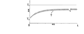
図3は、フレネルレンズ14の冷却を考慮せずに、キセノン管12を短い時間間隔で連続して発光するときのフレネルレンズ14の温度変化の様子を示すグラフである。図3において、横軸は時間、縦軸は温度であり、T0はフレネルレンズ14の初期温度、Tはフレネルレンズ14の温度変化を表わす。図3に示されるように、キセノン管12が発光されると、フレネルレンズ14の温度Tは略一定の値上昇し、発光終了とともに図2の冷却特性(曲線)に沿って下降する。しかし、フレネルレンズ14の温度Tが上昇した後冷却される前にキセノン管12が発光されると、フレネルレンズ14に蓄積された熱は放熱しきれず、温度Tはキセノン管12の発光毎に漸次上昇する。
FIG. 3 is a graph showing the temperature change of the Fresnel
また、フレネルレンズ14の温度上昇に伴い、フレネルレンズ14表面と外気の間の温度差(温度勾配)は大きくなるため単位時間当たりの放熱量は増大し、温度上昇率は漸減する。出力一定(発光量一定)の下でのキセノン管12の1回の発光によるフレネルレンズ14の温度上昇は略一定であるため、放熱と蓄熱のバランスにより外気との温度差が一定値を超えるとキセノン管12の発光を繰り返しても、フレネルレンズ14の温度Tは、図3に示されるように略一定の温度に留まる。
Further, as the temperature of the Fresnel
温度上昇の仕方は、キセノン管12の出力(発光量)と発光間隔により変動し、出力(発光量)が一定であれば、発光間隔が大きいほど温度上昇率は下がり、また発光の繰り返しにより到達する最終的な温度も低下する。図3は、発光間隔が相対的に短く、最終温度がフレネルレンズ14の融解温度Tfを超える場合を例示している。なお、一定出力(発光量)下でのフレネルレンズ14の温度上昇の様子は予め測定され、その特性値が記録される。
The method of increasing the temperature varies depending on the output (light emission amount) of the
なお、フレネルレンズ14の現在温度Tnは、例えば以下の(1)式をフレネルレンズ14の初期温度から逐次計算することによりにより推定できる。
Tn = Tn-1 − hc(Tn-1 − T∞)Δt + hfW (1)
The current temperature T n of the
T n = T n−1 −h c (T n−1 −T∞) Δt + h f W (1)
ここで、右辺第2項はフレネルレンズ14と外気との間の温度勾配に比例する冷却項(放熱項)であり、第3項はキセノン管12の出力(発熱量)に比例する発熱項(加熱項)である。Tn-1は前回計算したフレネルレンズ14の温度であり、T∞は外気温(周辺の温度)である。T∞は、温度計17の測定値から直接的あるいは間接的に求められる。hcは熱伝達率を含む冷却の特性値であり、予め計測された測定値から得られ、カメラ10のメモリ(不図示)に記録されている。hfはキセノン管12の出力(発光量)からフレネルレンズ14の発熱量を求めるための発熱の特性値であり、予め計測された測定値から得られ、カメラ10のメモリ(不図示)に記録されている。またWは実際に発光されたキセノン管12の出力(発光量)、Δtは前回と今回の計算の間の経過時間(本処理の繰り返し周期)であり、カメラ10のメモリ(不図示)に記録されている。なお、フレネルレンズ14の初期温度はカメラ10の電源投入時などにおける温度計17の温度であり、外気温T∞に略等しいと考えられる。また、(1)式において発光に必要な時間はΔtに比べ十分に短いとしている。
Here, the second term on the right side is a cooling term (heat radiation term) proportional to the temperature gradient between the
本実施形態では、フレネルレンズ14の温度Tを例えば(1)式を用いた推定処理により常時計算し、これをモニタすることで、連続発光時におけるフラッシュ制御回路15によるキセノン管12の発光の有無、または発光間隔、出力(発光量)を制御する。判定の仕方としては、例えば推定される最新の温度Tnが閾値Tmeltよりも小さいか否か(Tn<Tmelt)で判定される。ここで閾値Tmeltは、例えばフレネルレンズ14の融解温度Tfに安全率を見込んだ値である。なお、温度Tの計算は、カメラの設定が「連続発光撮影」の場合、最初の発光時から演算を開始しても良いが、最初の数ショット後から演算を開始しても構わない。また、連続発光撮影を停止したときは演算も休止してもよい。また演算結果の履歴を揮発/不揮発メモリーに記憶することで、一旦連続性が休止しても、短時間で再開した場合に、前回の演算結果を流用できるように構成してもよい。
In the present embodiment, the temperature T of the
図4は、図3と同じ出力(発光量)で、発光間隔を相対的に長くすることで、最終温度を融解温度Tfより低くした場合を例示する。例えば、上記判定から温度Tnが閾値Tmeltよりも大きい(Tn>Tmelt)と判定される場合には、発光間隔を大きくし、フレネルレンズ14の温度Tが融解温度Tfを超えることを防止する。なお、温度Tnが閾値Tmeltよりも小さく(Tn<Tmelt)なった場合は、発光間隔を元に戻す、あるいは短くすることもできる。
FIG. 4 exemplifies a case where the final temperature is lower than the melting temperature T f by relatively increasing the light emission interval with the same output (light emission amount) as in FIG. 3. For example, when it is determined from the above determination that the temperature T n is larger than the threshold T melt (T n > T melt ), the light emission interval is increased and the temperature T of the
また、図5には、例えば連続発光中に発光量を倍にする必要が生じた場合に、発光間隔(発光禁止期間)を長くし、冷却時間を長くすることでフレネルレンズ14の温度Tの上昇を抑制する制御を例示する。すなわち、発光間隔を略倍にして発光量を倍にしても温度Tが融解温度Tfを超えることを防止する。
FIG. 5 shows the temperature T of the
以上のように、本実施形態によれば、外気温に対応する温度と光源の出力(発光量)から発光装置を構成する部材の温度を推定することができる。また、外気温に対応する温度は、AFセンサの補正等に用いられている温度計を流用することで取得できるため、新たなセンサの搭載を考慮する必要がなくその構成を簡略にすることができる。また、推定温度に基づきフラッシュの発光を制御することでフラッシュを構成する部材の過熱を防止することができる。 As described above, according to the present embodiment, the temperature of the members constituting the light emitting device can be estimated from the temperature corresponding to the outside air temperature and the output (light emission amount) of the light source. In addition, since the temperature corresponding to the outside air temperature can be obtained by diverting a thermometer used for AF sensor correction or the like, it is not necessary to consider mounting a new sensor, and the configuration can be simplified. it can. Further, by controlling the light emission of the flash based on the estimated temperature, overheating of members constituting the flash can be prevented.
なお本実施形態では、(1)式を用いて被加熱部材の温度を推定したが、温度の推定式は(1)式に限定されるものではない。また、フラッシュが自動ポップアップ式の場合には、推定温度が所定値以上の場合に収納を禁止し、熱のこもりを防止する制御を行ってもよい。なお、光源には、キセノン管の他に、LEDなどの光源を用いることもできる。また本実施形態では、温度が推定される被加熱部材としてフレネルレンズを例に説明を行なったが、対象となる被加熱部材は、光源の発光により蓄熱されるとともに外気への放熱により冷却される部材であればよい。例えば、発光部が拡散板や光学フィルタを備える場合には、これらの光源からの光を透過する部材の温度を推定して、光源制御を行ってもよい。 In the present embodiment, the temperature of the heated member is estimated using equation (1), but the temperature estimation equation is not limited to equation (1). Further, when the flash is an automatic pop-up type, the storage may be prohibited when the estimated temperature is equal to or higher than a predetermined value, and control for preventing heat accumulation may be performed. In addition to the xenon tube, a light source such as an LED can be used as the light source. In the present embodiment, the Fresnel lens is described as an example of the member to be heated whose temperature is estimated. However, the member to be heated is stored by light emission from the light source and cooled by heat radiation to the outside air. Any member may be used. For example, when the light emitting unit includes a diffusion plate or an optical filter, the light source control may be performed by estimating the temperature of a member that transmits light from these light sources.
本実施形態の温度計には、例えばサーミスタや熱電対などが用いられる。また、光源制御装置は、推定温度から被加熱部材の過熱をユーザに報知する過熱報知手段を更に備えてもよい。報知方法の例としては、文字情報やグラフィカル情報の表示器へ表示したり、ランプを点灯したりする視覚的な方法や、警告音のような聴覚的な方法が挙げられる。 A thermistor, a thermocouple, etc. are used for the thermometer of this embodiment, for example. The light source control device may further include an overheat notification unit that notifies the user of overheating of the heated member from the estimated temperature. Examples of the notification method include a visual method of displaying text information or graphical information on a display or lighting a lamp, and an auditory method such as a warning sound.
なお、本実施形態ではカメラを例に説明を行なったが、本発明は、周囲環境温度に対応する温度が測定できる温度計と、その発光により部材を加熱する光源を備える装置であれば適用でき、例えばカメラ付き携帯やスマートホンにも適用できる。 In this embodiment, the camera has been described as an example. However, the present invention can be applied to any device including a thermometer capable of measuring a temperature corresponding to the ambient environment temperature and a light source that heats a member by light emission. For example, it can also be applied to mobile phones with cameras and smart phones.
10 カメラ
11 フラッシュ発光部
12 キセノン管(光源)
13 リフレクタ
14 フレネルレンズ(被加熱部材)
15 フラッシュ制御回路
16 カメラ制御回路
17 温度計
10
13
15
Claims (11)
外気温に対応する温度および前記光源の発光量または出力から、前記光源の発光動作により加熱される部材の温度を推定する温度推定手段と
を備えることを特徴とする光源制御装置。 A light source control means capable of controlling the light emission amount or output of the light source;
And a temperature estimation unit configured to estimate a temperature of a member heated by a light emission operation of the light source from a temperature corresponding to an outside air temperature and a light emission amount or output of the light source.
Priority Applications (1)
| Application Number | Priority Date | Filing Date | Title |
|---|---|---|---|
| JP2016029298A JP2017146505A (en) | 2016-02-18 | 2016-02-18 | Light source control device and imaging device |
Applications Claiming Priority (1)
| Application Number | Priority Date | Filing Date | Title |
|---|---|---|---|
| JP2016029298A JP2017146505A (en) | 2016-02-18 | 2016-02-18 | Light source control device and imaging device |
Publications (1)
| Publication Number | Publication Date |
|---|---|
| JP2017146505A true JP2017146505A (en) | 2017-08-24 |
Family
ID=59683058
Family Applications (1)
| Application Number | Title | Priority Date | Filing Date |
|---|---|---|---|
| JP2016029298A Pending JP2017146505A (en) | 2016-02-18 | 2016-02-18 | Light source control device and imaging device |
Country Status (1)
| Country | Link |
|---|---|
| JP (1) | JP2017146505A (en) |
Citations (4)
| Publication number | Priority date | Publication date | Assignee | Title |
|---|---|---|---|---|
| JP2006194590A (en) * | 2005-01-11 | 2006-07-27 | Canon Inc | Optical apparatus, camera system, and interchangeable lens |
| JP2010008618A (en) * | 2008-06-26 | 2010-01-14 | Panasonic Corp | Flashing device |
| JP2010261993A (en) * | 2009-04-30 | 2010-11-18 | Nikon Corp | Remote illumination controller, remote illumination device, and remote illumination device system |
| JP2012037791A (en) * | 2010-08-10 | 2012-02-23 | Nikon Corp | Imaging apparatus |
-
2016
- 2016-02-18 JP JP2016029298A patent/JP2017146505A/en active Pending
Patent Citations (4)
| Publication number | Priority date | Publication date | Assignee | Title |
|---|---|---|---|---|
| JP2006194590A (en) * | 2005-01-11 | 2006-07-27 | Canon Inc | Optical apparatus, camera system, and interchangeable lens |
| JP2010008618A (en) * | 2008-06-26 | 2010-01-14 | Panasonic Corp | Flashing device |
| JP2010261993A (en) * | 2009-04-30 | 2010-11-18 | Nikon Corp | Remote illumination controller, remote illumination device, and remote illumination device system |
| JP2012037791A (en) * | 2010-08-10 | 2012-02-23 | Nikon Corp | Imaging apparatus |
Similar Documents
| Publication | Publication Date | Title |
|---|---|---|
| JP2009300742A5 (en) | ||
| JP2015170708A5 (en) | ||
| JP4561396B2 (en) | Imaging device | |
| JP2017146505A (en) | Light source control device and imaging device | |
| JP2001338780A (en) | Determination of luminance and irradiation time of led by software | |
| JP5247258B2 (en) | Flash device | |
| JP2007322741A5 (en) | ||
| JP2012220787A (en) | Imaging apparatus and camera system | |
| JP2012048001A (en) | Light emitting device | |
| CN111629493B (en) | Lighting device having function of cooling light-emitting part and control method thereof | |
| JP2015040972A5 (en) | ||
| US20140104809A1 (en) | Electronic Flash Device | |
| JP2021081621A (en) | Lighting device, method for controlling the same, and imaging system | |
| JP5228636B2 (en) | Flash device and optical apparatus | |
| JP2015114465A5 (en) | ||
| JP5224757B2 (en) | Strobe device, imaging device, and camera system | |
| JP6884539B2 (en) | Projection type display device | |
| JP4481396B2 (en) | Camera, strobe device and camera system | |
| JP2016151714A5 (en) | ||
| JP5521812B2 (en) | Temperature detection device, electronic flash device, and camera | |
| JP6429495B2 (en) | Imaging apparatus and control method thereof, illumination apparatus, and program | |
| JP2020076906A (en) | Illumination device and control method therefor | |
| JP2013228660A (en) | Illumination device | |
| JP2012055421A (en) | Radiographic apparatus | |
| JP2020118723A (en) | Imaging apparatus, control method thereof, and control program |
Legal Events
| Date | Code | Title | Description |
|---|---|---|---|
| A621 | Written request for application examination |
Free format text: JAPANESE INTERMEDIATE CODE: A621 Effective date: 20181211 |
|
| A977 | Report on retrieval |
Free format text: JAPANESE INTERMEDIATE CODE: A971007 Effective date: 20191021 |
|
| A131 | Notification of reasons for refusal |
Free format text: JAPANESE INTERMEDIATE CODE: A131 Effective date: 20191029 |
|
| A02 | Decision of refusal |
Free format text: JAPANESE INTERMEDIATE CODE: A02 Effective date: 20200428 |