JP2017145109A - Sheet storage cassette and image formation apparatus having the same - Google Patents

Sheet storage cassette and image formation apparatus having the same Download PDF

Info

Publication number
JP2017145109A
JP2017145109A JP2016028625A JP2016028625A JP2017145109A JP 2017145109 A JP2017145109 A JP 2017145109A JP 2016028625 A JP2016028625 A JP 2016028625A JP 2016028625 A JP2016028625 A JP 2016028625A JP 2017145109 A JP2017145109 A JP 2017145109A
Authority
JP
Japan
Prior art keywords
cursor
sheet
paper
housing
cassette
Prior art date
Legal status (The legal status is an assumption and is not a legal conclusion. Google has not performed a legal analysis and makes no representation as to the accuracy of the status listed.)
Pending
Application number
JP2016028625A
Other languages
Japanese (ja)
Inventor
智也 穂谷
Tomoya Hotani
智也 穂谷
Current Assignee (The listed assignees may be inaccurate. Google has not performed a legal analysis and makes no representation or warranty as to the accuracy of the list.)
Kyocera Document Solutions Inc
Original Assignee
Kyocera Document Solutions Inc
Priority date (The priority date is an assumption and is not a legal conclusion. Google has not performed a legal analysis and makes no representation as to the accuracy of the date listed.)
Filing date
Publication date
Application filed by Kyocera Document Solutions Inc filed Critical Kyocera Document Solutions Inc
Priority to JP2016028625A priority Critical patent/JP2017145109A/en
Publication of JP2017145109A publication Critical patent/JP2017145109A/en
Pending legal-status Critical Current

Links

Images

Landscapes

  • Sheets, Magazines, And Separation Thereof (AREA)

Abstract

PROBLEM TO BE SOLVED: To provide a sheet storage cassette which can suppress the deviation of a cursor member at the cassette insertion due to the weight of a sheet with a simple configuration, and an image formation apparatus having the same.SOLUTION: A sheet storage cassette includes: a housing; a cursor member; and a lock mechanism, and is detachably attached to an image formation apparatus body. The housing is formed of a cassette base and a plurality of side walls erected on the circumference of the cassette base, and stores a sheet-like recording medium. A cursor member is provided movably in the cassette base of the housing and performs positioning of the sheet by contacting the edge of the sheet stored in the housing. A lock mechanism regulates movement of the cursor member with respect to the cassette base when the sheets stored in the housing are equal to or greater than the prescribed number.SELECTED DRAWING: Figure 3

Description

本発明は、デジタル複写機、レーザープリンター等の画像形成装置に用いられる、シート状の記録媒体を収納するシート収納カセット及びそれを備えた画像形成装置に関するものである。   The present invention relates to a sheet storage cassette for storing a sheet-like recording medium used in an image forming apparatus such as a digital copying machine and a laser printer, and an image forming apparatus including the same.

従来、シート状の用紙(記録媒体)を複数枚積載して収納するとともに、画像形成動作に応じて画像形成装置本体の画像形成部へ用紙を1枚ずつ分離して搬送する給紙カセットが広く用いられている。このような給紙カセットは、用紙の補給時における操作性を考慮して、画像形成装置本体に対し挿入及び引き出し可能とされている。   2. Description of the Related Art Conventionally, there are a wide variety of sheet feeding cassettes that stack and store a plurality of sheet-like sheets (recording media) and separate and convey sheets one by one to an image forming unit of an image forming apparatus main body according to an image forming operation. It is used. Such a paper feed cassette can be inserted into and pulled out from the image forming apparatus main body in consideration of operability when replenishing paper.

また、給紙カセットには、用紙を給紙カセット内の所定位置に収納するための幅合わせカーソル及び後端カーソルから成るカーソル部材が配置されている。これらのカーソル部材を積載される用紙サイズに合わせて移動させることにより、用紙を給紙位置に位置決めする。   In addition, a cursor member including a width alignment cursor and a rear end cursor for storing paper at a predetermined position in the paper feed cassette is disposed in the paper feed cassette. By moving these cursor members according to the size of the stacked paper, the paper is positioned at the paper feed position.

ここで、用紙の積載量が多い状態で給紙カセットを画像形成装置本体へ挿入すると、用紙の重量によりカーソル部材に大きな負荷が加わり、カーソル部材が予め位置決めされた位置からずれることがある。カーソル部材の位置がずれると、カーソル部材によって規制される用紙位置もずれるため、画像位置ずれや給紙不良等の不具合が発生するという問題点があった。   Here, when the paper feeding cassette is inserted into the image forming apparatus main body with a large amount of paper loaded, a large load is applied to the cursor member due to the weight of the paper, and the cursor member may deviate from the position previously positioned. When the position of the cursor member is deviated, the paper position regulated by the cursor member is also deviated, which causes problems such as image position deviation and paper feed failure.

そこで、カーソル部材の不用意な移動を防止する方法が提案されており、例えば特許文献1には、鋸歯状のラック歯を有するラックを案内レールと平行に設けておき、後端カーソルに取り付けられたロックレバーを所定の位置でラックに係合させるロック機構を備えた給紙カセットが開示されている。また、特許文献2には、第1のガイド部材の固定を凹凸嵌合によって行うとともに、第1のガイド部材の撓み変形によってその凹凸嵌合による固定を解除するようにした給紙カセットが開示されている。   Therefore, a method for preventing inadvertent movement of the cursor member has been proposed. For example, in Patent Document 1, a rack having sawtooth rack teeth is provided in parallel with the guide rail and attached to the rear end cursor. A paper feed cassette having a lock mechanism for engaging a lock lever with a rack at a predetermined position is disclosed. Patent Document 2 discloses a paper feed cassette in which the first guide member is fixed by concave and convex fitting, and the fixing by the concave and convex fitting is released by bending deformation of the first guide member. ing.

特開2001−187642号公報JP 2001-187642 A 特開2010−52903号公報JP 2010-52903 A

特許文献1、2のように、カーソル部材をロックする専用のロック機構を設けた場合であっても、ラック歯や凹凸の係合が浅い場合は給紙カセットの挿入時にカーソル部材に加わる負荷によってロック機構の係合が外れ、カーソル部材の位置ずれが発生するおそれがあった。   Even when a dedicated locking mechanism for locking the cursor member is provided as in Patent Documents 1 and 2, if the rack teeth or unevenness are shallowly engaged, the load applied to the cursor member during insertion of the paper feed cassette There is a possibility that the lock mechanism is disengaged and the cursor member is displaced.

また、カーソル部材を強固にロックできるロック機構を設けた場合、カーソル部材の位置ずれは防止できるものの、ユーザーがロック機構の操作を忘れるとカーソル部材がロックされず、給紙カセット内で用紙の位置ずれが発生するおそれがあった。   In addition, if a lock mechanism that can firmly lock the cursor member is provided, it is possible to prevent displacement of the cursor member, but if the user forgets to operate the lock mechanism, the cursor member will not be locked and the position of the paper in the paper cassette There was a risk of misalignment.

本発明は、上記問題点に鑑み、シートの重量によるカセット挿入時のカーソル部材のずれを簡易な構成で抑制可能なシート収納カセット及びそれを備えた画像形成装置を提供することを目的とする。   SUMMARY An advantage of some aspects of the invention is that it provides a sheet storage cassette and an image forming apparatus including the sheet storage cassette that can suppress the displacement of a cursor member due to the weight of the sheet when the cassette is inserted with a simple configuration.

上記目的を達成するために本発明の第1の構成は、ハウジングと、カーソル部材と、ロック機構と、を備え、画像形成装置本体に対し着脱可能に装着されるシート収納カセットである。ハウジングは、カセットベース及びカセットベースの周縁部に立設される複数の側壁で構成され、シート状の記録媒体を収納する。カーソル部材は、ハウジングのカセットベースに移動可能に設けられ、ハウジング内に収納されたシートの端縁に当接してシートの位置決めを行う規制面と、規制面の下端からベースに沿って内側に延びる支持面と、を有する。ロック機構は、カーソル部材の支持面に上下方向に揺動可能に設けられる係合部材と、カセットベースに形成され、カーソル部材が所定サイズのシートの端縁に当接する位置に配置されたとき係合部材に対向する係合溝と、を有し、カセットベースに対する前記カーソル部材の移動を規制する。係合部材は、ハウジング内に収納されるシートが所定枚数未満のとき、支持面の上方に突出して係合溝から離間することによりカーソル部材の移動を許容する第1の位置に配置され、ハウジング内に収納されるシートが所定枚数以上のとき、支持面の下方に埋没して係合溝に係合することにより係合溝に係合してカーソル部材の移動を規制する第2の位置に配置される。   In order to achieve the above object, a first configuration of the present invention is a sheet storage cassette that includes a housing, a cursor member, and a lock mechanism, and is detachably attached to the main body of the image forming apparatus. The housing is composed of a cassette base and a plurality of side walls erected on the peripheral edge of the cassette base, and accommodates a sheet-like recording medium. The cursor member is movably provided on the cassette base of the housing, and is in contact with the edge of the sheet stored in the housing to position the sheet, and extends inwardly from the lower end of the restriction surface along the base. And a support surface. The lock mechanism is an engagement member provided on the support surface of the cursor member so as to be swingable in the vertical direction, and is formed on the cassette base, and is engaged when the cursor member is disposed at a position where it abuts against an edge of a sheet of a predetermined size. An engaging groove facing the coupling member, and restricts movement of the cursor member relative to the cassette base. The engaging member is disposed at a first position that allows the movement of the cursor member by projecting upward from the support surface and separating from the engaging groove when the number of sheets stored in the housing is less than a predetermined number. When the number of sheets stored therein is equal to or greater than a predetermined number, the second position is set so as to be engaged with the engagement groove by restricting the movement of the cursor member by being buried below the support surface and engaging with the engagement groove. Be placed.

本発明の第1の構成によれば、カーソル部材を予めハウジング内に収納するシートサイズに応じた位置に合わせておき、所定枚数以上のシートを積載するだけで、係合部材が第2の位置に配置されてカーソル部材の移動が規制される。また、画像形成装置にシート収納カセットを挿入した後、印字動作によりシートが所定枚数よりも少なくなると、係合部材が第1の位置に配置されてカーソル部材のロックが自動的に解除される。従って、シートの積載枚数(積載量)が多い状態で画像形成装置にシート収納カセットを挿入する際のカーソル部材の位置ずれ、及びそれに起因する画像位置ずれやシート給送不良を確実に防止することができる。また、ユーザーがカーソル部材の移動を規制(ロック)する操作や、画像形成装置からシート収納カセットを引き出してシートを補給する際にロックを解除する操作も不要となる。   According to the first configuration of the present invention, the engagement member is moved to the second position only by stacking a predetermined number of sheets or more by previously setting the cursor member at a position corresponding to the sheet size stored in the housing. The movement of the cursor member is restricted. Further, after the sheet storage cassette is inserted into the image forming apparatus, when the number of sheets is less than a predetermined number by the printing operation, the engaging member is disposed at the first position and the cursor member is automatically unlocked. Accordingly, it is possible to reliably prevent the displacement of the cursor member when inserting the sheet storage cassette into the image forming apparatus in a state where the number of stacked sheets (stacking amount) is large, and the image position displacement and sheet feeding failure caused by the displacement. Can do. Further, there is no need for an operation for the user to restrict (lock) the movement of the cursor member or an operation for releasing the lock when the sheet storage cassette is pulled out from the image forming apparatus to replenish the sheet.

本発明の給紙カセット2が搭載される画像形成装置100の内部構成を示す概略断面図1 is a schematic cross-sectional view showing an internal configuration of an image forming apparatus 100 in which a paper feed cassette 2 of the present invention is mounted. 本発明の第1実施形態に係る給紙カセット2の外観斜視図1 is an external perspective view of a paper feed cassette 2 according to the first embodiment of the present invention. 第1実施形態の給紙カセット2の平面図The top view of the paper feed cassette 2 of the first embodiment 第1実施形態の給紙カセット2を幅合わせカーソル37aの幅規制部41近傍で給紙方向に沿って切断した側面断面図Side surface sectional drawing which cut | disconnected the paper feed cassette 2 of 1st Embodiment along the paper feed direction in the width regulation part 41 vicinity of the width alignment cursor 37a. 幅合わせカーソル37aを用紙幅方向に沿って切断した側面断面図Side sectional view of the width alignment cursor 37a cut along the paper width direction 図4におけるロック機構60周辺の部分拡大図であり、用紙積載板28上に用紙26が積載されていない状態を示す図FIG. 5 is a partially enlarged view of the periphery of the lock mechanism 60 in FIG. 4, showing a state where the paper 26 is not stacked on the paper stacking plate 28. 図4におけるロック機構60周辺の部分拡大図であり、用紙積載板28上に所定枚数の用紙26が積載された状態を示す図FIG. 5 is a partially enlarged view of the periphery of the lock mechanism 60 in FIG. 4, showing a state where a predetermined number of sheets 26 are stacked on the sheet stacking plate 28. 本発明の第2実施形態に係る給紙カセット2の平面図The top view of the paper feed cassette 2 which concerns on 2nd Embodiment of this invention. 第2実施形態の給紙カセット2を幅合わせカーソル37aの幅規制部41近傍で給紙方向に沿って切断した側面断面図Side surface sectional drawing which cut | disconnected the paper feed cassette 2 of 2nd Embodiment along the paper feed direction in the width regulation part 41 vicinity of the width alignment cursor 37a. 本発明の第3実施形態に係る給紙カセット2におけるロック機構60周辺の部分拡大図であり、用紙積載板28上に用紙26が積載されていない状態を示す図FIG. 9 is a partially enlarged view of the periphery of a lock mechanism 60 in a paper feed cassette 2 according to a third embodiment of the present invention, and shows a state in which no paper is stacked on a paper stacking plate. 第3実施形態の給紙カセット2におけるロック機構60周辺の部分拡大図であり、用紙積載板28上に所定枚数の用紙26が積載された状態を示す図FIG. 10 is a partially enlarged view of the periphery of the lock mechanism 60 in the paper feed cassette 2 of the third embodiment, and shows a state in which a predetermined number of sheets 26 are stacked on the sheet stacking plate 28.

以下、図面を参照しながら本発明の実施形態を詳細に説明する。図1は、本発明の一実施形態に係る給紙カセット2を備えた画像形成装置100の概略断面図である。なお、ここでは画像形成装置100として、モノクロ複合機について示している。画像形成装置100本体内には、帯電、露光、現像及び転写の各工程によりモノクロ画像を形成する画像形成部Pが配設されている。   Hereinafter, embodiments of the present invention will be described in detail with reference to the drawings. FIG. 1 is a schematic cross-sectional view of an image forming apparatus 100 including a paper feed cassette 2 according to an embodiment of the present invention. Here, a monochrome multifunction peripheral is shown as the image forming apparatus 100. In the main body of the image forming apparatus 100, an image forming portion P for forming a monochrome image by each process of charging, exposure, development and transfer is disposed.

画像形成部Pには、感光体ドラム1の回転方向(図1の反時計回り方向)に沿って、帯電部10、露光ユニット3、現像装置4、転写ローラー7、クリーニング装置8、及び除電装置(図示せず)が配設されている。画像形成部Pでは、感光体ドラム1を図1において反時計回り方向に回転させながら、感光体ドラム1に対する画像形成プロセスが実行される。   In the image forming unit P, along the rotation direction of the photosensitive drum 1 (counterclockwise direction in FIG. 1), the charging unit 10, the exposure unit 3, the developing device 4, the transfer roller 7, the cleaning device 8, and the charge eliminating device. (Not shown) is provided. In the image forming unit P, the image forming process for the photosensitive drum 1 is executed while rotating the photosensitive drum 1 in the counterclockwise direction in FIG.

コピー動作を行う場合、画像読取部21において原稿の画像データを読み取り画像信号に変換する。一方、画像形成部Pにおいて、帯電部10により図中の反時計回り方向に回転する感光体ドラム1が一様に帯電される。そして、画像読取部21で読み取られた原稿画像データに基づいて露光ユニット3から感光体ドラム1上にレーザービーム(光線)を照射することで、その画像データに基づく静電潜像を感光体ドラム1表面に形成する。その後、現像装置4が静電潜像にトナーを付着させてトナー像を形成する。   When performing the copy operation, the image reading unit 21 reads the image data of the document and converts it into an image signal. On the other hand, in the image forming unit P, the photosensitive drum 1 that rotates counterclockwise in the drawing is uniformly charged by the charging unit 10. Then, the exposure unit 3 irradiates the photosensitive drum 1 with a laser beam (light beam) based on the document image data read by the image reading unit 21, whereby the electrostatic latent image based on the image data is converted into the photosensitive drum. 1 formed on the surface. Thereafter, the developing device 4 attaches toner to the electrostatic latent image to form a toner image.

上記のようにトナー像が形成された画像形成部Pに向けて、給紙カセット2から用紙26が用紙搬送路11及びレジストローラー対13を経由して所定のタイミングで搬送され、画像形成部Pにおいて転写ローラー7により感光体ドラム1表面のトナー像が用紙に転写される。そして、トナー像が転写された用紙26は感光体ドラム1から分離され、定着部9に搬送されて加熱及び加圧されることで用紙26にトナー像が定着される。   A sheet 26 is conveyed from the sheet feeding cassette 2 through the sheet conveying path 11 and the registration roller pair 13 at a predetermined timing toward the image forming section P on which the toner image is formed as described above. Then, the toner image on the surface of the photosensitive drum 1 is transferred onto the sheet by the transfer roller 7. The paper 26 onto which the toner image has been transferred is separated from the photosensitive drum 1, conveyed to the fixing unit 9, and heated and pressurized to fix the toner image on the paper 26.

定着部9を通過した用紙26は、複数方向に分岐した分岐部16によって搬送方向が振り分けられる。用紙26の片面のみに画像を形成する場合は、そのまま排出ローラー対14によって排出トレイ15に排出される。   The paper 26 that has passed through the fixing unit 9 is distributed in the conveyance direction by the branching unit 16 that branches in a plurality of directions. When an image is formed on only one side of the paper 26, it is discharged as it is onto the discharge tray 15 by the discharge roller pair 14.

一方、用紙26の両面に画像を形成する場合は、定着部9を通過した用紙26は一旦排出ローラー対14方向に搬送され、用紙26の後端が分岐部16を通過した後に排出ローラー対14を逆回転させるとともに分岐部16の搬送方向を切り換えることで、用紙26の後端から反転搬送路17に振り分けられ、画像面を反転させた状態でレジストローラー対13に再搬送される。そして、感光体ドラム1上に形成された次の画像が転写ローラー7により用紙26の画像が形成されていない面に転写され、定着部9に搬送されてトナー像が定着された後、排出トレイ15に排出される。   On the other hand, when forming images on both sides of the paper 26, the paper 26 that has passed through the fixing unit 9 is once transported in the direction of the discharge roller pair 14, and after the trailing edge of the paper 26 passes through the branching portion 16, the discharge roller pair 14. Is rotated in the reverse direction and the conveyance direction of the branching portion 16 is switched, so that the paper 26 is distributed from the rear end of the paper 26 to the reverse conveyance path 17 and re-conveyed to the registration roller pair 13 with the image surface reversed. Then, the next image formed on the photosensitive drum 1 is transferred to the surface of the paper 26 where the image is not formed by the transfer roller 7 and conveyed to the fixing unit 9 to fix the toner image, and then the discharge tray. 15 is discharged.

次に、給紙カセット2の構成について説明する。図2及び図3は、それぞれ本発明の第1実施形態に係る給紙カセット2の斜視図及び平面図であり、図4は、給紙カセット2を幅合わせカーソル37aの幅規制部41近傍で給紙方向に沿って切断した側面断面図(図3のAA矢視断面図)、図5は、幅合わせカーソル37aを用紙幅方向に沿って切断した側面断面図である。図2及び図3において、画像形成装置100に対する給紙カセット2の挿入方向を矢印B、引き出し方向を矢印B′で示し、給紙カセット2の給紙方向を矢印Cで示す。カセットベース25は、給紙カセット2のハウジング(筐体)を構成するものであり、矩形状の底面の四辺に側壁25a〜25dが形成されたトレイ状をなしている。   Next, the configuration of the paper feed cassette 2 will be described. 2 and 3 are a perspective view and a plan view, respectively, of the paper feed cassette 2 according to the first embodiment of the present invention, and FIG. 4 shows the paper feed cassette 2 in the vicinity of the width regulating portion 41 of the width alignment cursor 37a. FIG. 5 is a side cross-sectional view taken along the paper width direction (cross-sectional view taken along arrow AA in FIG. 3), and FIG. 5 is a side cross-sectional view taken along the paper width direction. 2 and 3, the insertion direction of the paper feed cassette 2 with respect to the image forming apparatus 100 is indicated by an arrow B, the pull-out direction is indicated by an arrow B ′, and the paper feed direction of the paper feed cassette 2 is indicated by an arrow C. The cassette base 25 constitutes a housing (housing) of the paper feed cassette 2 and has a tray shape in which side walls 25a to 25d are formed on four sides of a rectangular bottom surface.

給紙カセット2の挿入方向に対し下流側の側壁25aにはカセットカバー33が装着されている。カセットカバー33は、その表面側(図2の左手前側)が外部に露出して画像形成装置100(図1参照)本体の外装面の一部を構成する。なお、図3ではカセットカバー33を取り外した状態を示している。   A cassette cover 33 is mounted on the side wall 25a on the downstream side with respect to the insertion direction of the paper feed cassette 2. The cassette cover 33 has a surface side (the left front side in FIG. 2) exposed to the outside and constitutes a part of the exterior surface of the image forming apparatus 100 (see FIG. 1) main body. FIG. 3 shows a state where the cassette cover 33 is removed.

用紙26(図1参照)が積載される用紙積載板28は、給紙方向上流側(図3の左側)の揺動軸28aを支点として支持されており、給紙方向下流側(図3の右側)の端部がコイルバネ(図示せず)によってカセットベース25に対し上下に昇降可能に設けられている。   The paper stacking plate 28 on which the paper 26 (see FIG. 1) is loaded is supported by using the swing shaft 28a on the upstream side in the paper feeding direction (left side in FIG. 3) as a fulcrum, and downstream in the paper feeding direction (in FIG. 3). An end portion on the right side is provided so as to be movable up and down with respect to the cassette base 25 by a coil spring (not shown).

用紙積載板28の幅方向両側には、用紙積載板28に積載される用紙26の幅方向の位置決めを行う一対の幅合わせカーソル37a、37bが、カセットベース25の底面に形成された案内溝38aに沿ってそれぞれ用紙幅方向(図の矢印BB′方向)に往復移動可能に設けられている。   On both sides in the width direction of the paper stacking plate 28, a pair of width alignment cursors 37 a and 37 b for positioning the paper 26 stacked on the paper stacking plate 28 in the width direction are formed in guide grooves 38 a formed on the bottom surface of the cassette base 25. Along the sheet width direction (in the direction of arrow BB 'in the figure).

幅合わせカーソル37a、37bは、カセットベース25の底面から垂直に立設される幅規制部41と、幅規制部41の下端部から水平方向に延在し、案内溝38aに沿って配置されるラック部43とを有し、給紙方向(図3の右方向)から見た形状が略L字形をなしている。幅規制部41は、用紙積載板28に載置される用紙26の側端縁に当接する。各ラック部43の給紙方向の対向面には、用紙幅方向に延びるラック歯が形成されている。   The width alignment cursors 37a and 37b extend in a horizontal direction from a width restricting portion 41 that stands vertically from the bottom surface of the cassette base 25 and from a lower end portion of the width restricting portion 41, and are arranged along the guide groove 38a. The shape seen from the paper feeding direction (right direction in FIG. 3) is substantially L-shaped. The width restricting portion 41 contacts the side edge of the paper 26 placed on the paper stacking plate 28. Rack teeth extending in the paper width direction are formed on the opposing surfaces of the rack portions 43 in the paper feeding direction.

幅規制部41の用紙幅方向(図3の上下方向)へのスライド移動とともに、ラック部43も用紙幅方向に移動する。なお、2個の幅合わせカーソル37a、37bの各ラック部43は、給紙方向(図3の左右方向)に位置をずらして配置されているので、用紙幅方向に移動しても互いが衝突することはない。   As the width restricting portion 41 slides in the paper width direction (vertical direction in FIG. 3), the rack portion 43 also moves in the paper width direction. Note that the rack portions 43 of the two width alignment cursors 37a and 37b are arranged with their positions shifted in the paper feeding direction (left and right direction in FIG. 3), so that they collide with each other even if they move in the paper width direction. Never do.

カセットベース25の略中央部に配置されるピニオンギア(図示せず)と各ラック部43のラック歯とで構成されるラック&ピニオン機構により、一方の幅合わせカーソル37aを用紙幅方向に移動させると、これに連動して他方の幅合わせカーソル37bも反対方向に移動する。即ち、各幅合わせカーソル37、37bは用紙幅方向の中心線に対して左右対称に移動する。   One width alignment cursor 37a is moved in the paper width direction by a rack and pinion mechanism constituted by a pinion gear (not shown) arranged at a substantially central portion of the cassette base 25 and rack teeth of each rack portion 43. In conjunction with this, the other width alignment cursor 37b also moves in the opposite direction. That is, the width alignment cursors 37 and 37b move symmetrically with respect to the center line in the paper width direction.

また、幅合わせカーソル37aには、カセットベース25に対し幅合わせカーソル37a、37bを任意の位置で固定するための位置規制機構50が設けられている。位置規制機構50は、図5に示すように、幅規制部41の背面側(用紙の当接面と反対側)に設けられた位置規制部45と、幅規制部41と位置規制部45の間に配置されるコイルバネ46と、を含む。   Further, the width adjusting cursor 37a is provided with a position regulating mechanism 50 for fixing the width adjusting cursors 37a and 37b to the cassette base 25 at arbitrary positions. As shown in FIG. 5, the position restricting mechanism 50 includes a position restricting portion 45 provided on the back side of the width restricting portion 41 (on the side opposite to the sheet contact surface), and the width restricting portion 41 and the position restricting portion 45. A coil spring 46 disposed therebetween.

位置規制部45の下端部には係合爪45aが形成されている。係合爪45aは、カセットベース25の底面に案内溝38a(図3参照)に沿って連続的に形成されたラック歯25eに係合するように形成されている。そして、幅合わせカーソル37aの移動に伴って、係合爪45aとラック歯25eの係合位置が移動する。また、位置規制部45の上方にはレバー部45bが形成されている。   An engaging claw 45 a is formed at the lower end of the position restricting portion 45. The engaging claw 45a is formed so as to engage with the rack teeth 25e formed continuously along the guide groove 38a (see FIG. 3) on the bottom surface of the cassette base 25. Then, with the movement of the width alignment cursor 37a, the engagement positions of the engagement claws 45a and the rack teeth 25e move. A lever portion 45 b is formed above the position restricting portion 45.

レバー部45bに力を加えない図5の状態では、コイルバネ46の付勢力により幅合わせカーソル37aの下端から係合爪45aが突出してカセットベース25の底面に形成されたラック歯25eに係合している。これにより、幅合わせカーソル37aの用紙幅方向への移動が規制されている。前述したように、幅合わせカーソル37bはラック&ピニオン機構により幅合わせカーソル37aに連動して移動するため、幅合わせカーソル37aの移動を規制することで幅合わせカーソル37bの移動も規制される。   In the state of FIG. 5 in which no force is applied to the lever portion 45b, the engaging claw 45a protrudes from the lower end of the width alignment cursor 37a by the biasing force of the coil spring 46 and engages with the rack teeth 25e formed on the bottom surface of the cassette base 25. ing. As a result, the movement of the width alignment cursor 37a in the paper width direction is restricted. As described above, since the width alignment cursor 37b moves in conjunction with the width alignment cursor 37a by the rack and pinion mechanism, the movement of the width alignment cursor 37b is also restricted by restricting the movement of the width alignment cursor 37a.

図5の状態から、位置規制部45のレバー部45bを幅規制部41と共に把持することにより、位置規制部45がレバー部45bと共にカセットベース25に対し幅規制部41側に弾性変形する。その結果、係合爪45aが上方に退避してラック歯25eとの係合が解除され、幅合わせカーソル37a、37bが移動可能となる。   When the lever part 45b of the position restricting part 45 is gripped together with the width restricting part 41 from the state of FIG. 5, the position restricting part 45 is elastically deformed toward the width restricting part 41 with respect to the cassette base 25 together with the lever part 45b. As a result, the engaging claw 45a is retracted upward, the engagement with the rack tooth 25e is released, and the width alignment cursors 37a and 37b can be moved.

幅合わせカーソル37a、37bを用紙26の幅に合わせて移動した後、レバー部45bを把持していた指を離すことにより、コイルバネ46の付勢力によって再び幅合わせカーソル37aの下端から係合爪45aが突出してラック歯25eに係合する。これにより、幅合わせカーソル37a、37bが用紙幅方向の所定の位置に保持される。   After the width adjusting cursors 37a and 37b are moved in accordance with the width of the paper 26, the engaging claws 45a are again moved from the lower end of the width adjusting cursor 37a by the biasing force of the coil spring 46 by releasing the finger holding the lever portion 45b. Protrudes and engages with the rack teeth 25e. As a result, the width alignment cursors 37a and 37b are held at predetermined positions in the paper width direction.

また、用紙搬送路11(図1参照)に向けて用紙26が矢印B′方向(図2参照)に送出されるため、用紙26の後端を揃える後端カーソル31は、カセットベース25に形成された案内溝38bに沿って給紙方向(図3の矢印C方向)と平行に往復移動可能に設けられている。なお、ここでは説明を省略するが、後端カーソル31にも幅合わせカーソル37aと同様の構成の位置規制機構が設けられている。   Further, since the paper 26 is sent in the direction of the arrow B ′ (see FIG. 2) toward the paper transport path 11 (see FIG. 1), a rear end cursor 31 for aligning the rear end of the paper 26 is formed on the cassette base 25. The guide groove 38b is provided so as to be reciprocally movable in parallel with the paper feeding direction (the direction of arrow C in FIG. 3). Although explanation is omitted here, the rear end cursor 31 is also provided with a position regulating mechanism having the same configuration as the width alignment cursor 37a.

この幅合わせカーソル37a、37b、及び後端カーソル31を、用紙積載板28に積載される用紙26のサイズに合わせて移動させることにより、用紙26を給紙カセット2内の所定位置に収納する。   By moving the width alignment cursors 37a and 37b and the rear end cursor 31 in accordance with the size of the paper 26 stacked on the paper stacking plate 28, the paper 26 is stored in a predetermined position in the paper feed cassette 2.

上述のように、幅合わせカーソル37a、37bには位置規制機構50が設けられているが、幅合わせカーソル37a、37bの移動方向に負荷が加わると、係合爪45aとラック歯25eとの係合が外れることがある。特に、上述したように給紙カセット2の挿入方向と給紙方向とが直交する場合、給紙カセット2の挿入方向に沿って幅合わせカーソル37a、37bが移動するため、用紙積載板28上の用紙26の積載量が多い状態で給紙カセット2を画像形成装置100本体へ挿入すると、挿入時の衝撃によって用紙26から挿入方向に対し下流側に位置する幅合わせカーソル37aに大きな負荷が加わり、幅合わせカーソル37a、及びラック&ピニオン機構により幅合わせカーソル37aに連結される幅合わせカーソル37bがずれるおそれがある。   As described above, the position adjusting mechanism 50 is provided in the width alignment cursors 37a and 37b. However, when a load is applied in the movement direction of the width alignment cursors 37a and 37b, the engagement between the engagement claws 45a and the rack teeth 25e. Mismatch may occur. In particular, as described above, when the insertion direction of the paper feed cassette 2 and the paper feed direction are orthogonal to each other, the width alignment cursors 37a and 37b move along the insertion direction of the paper feed cassette 2. When the paper feed cassette 2 is inserted into the main body of the image forming apparatus 100 with a large amount of paper 26 loaded, a large load is applied to the width alignment cursor 37a positioned downstream from the paper 26 with respect to the insertion direction due to an impact at the time of insertion. There is a possibility that the width alignment cursor 37a and the width alignment cursor 37b connected to the width alignment cursor 37a by the rack and pinion mechanism may be shifted.

そこで、幅合わせカーソル37aの給紙方向上流側の端部には、用紙積載板28上の用紙26の積載量に応じてカセットベース25に対する幅合わせカーソル37aの移動を規制(ロック)するためのロック機構60が設けられている。以下、ロック機構60の詳細な構成について説明する。   Therefore, the end of the width alignment cursor 37a on the upstream side in the paper feeding direction is for restricting (locking) the movement of the width alignment cursor 37a with respect to the cassette base 25 according to the stacking amount of the paper 26 on the paper stacking plate 28. A lock mechanism 60 is provided. Hereinafter, a detailed configuration of the lock mechanism 60 will be described.

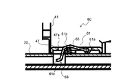
図6及び図7は、図4におけるロック機構60周辺(図4の破線円S内)の部分拡大図である。図6は用紙積載板28上に用紙26が積載されていない状態を示しており、図7は用紙積載板28上に所定枚数以上の用紙26が積載された状態を示している。なお、図7では用紙26の記載を省略している。   6 and 7 are partially enlarged views of the periphery of the lock mechanism 60 in FIG. 4 (inside the broken-line circle S in FIG. 4). FIG. 6 shows a state in which the paper 26 is not stacked on the paper stacking plate 28, and FIG. 7 shows a state in which a predetermined number of sheets 26 or more are stacked on the paper stacking plate 28. In FIG. 7, the description of the paper 26 is omitted.

ロック機構60は、幅合わせカーソル37aの幅規制部41の用紙給送方向後端の下端部から内側に向けて、カセットベース25の底面に沿って突出する係合部材支持部47に支持された係合部材61と、カセットベース25側に形成された係合溝63と、圧縮バネ65とを含む。係合部材61は側面視V字形状の棒状または板状の部材であり、係合部材支持部47に揺動可能に支持される支点部61aと、支点部61aから上方に凸形状となるように延在する屈曲部61bと、を有している。係合溝63は、係合部材61が幅方向(図6の紙面と垂直な方向)において挿入可能な程度の溝幅を有する。   The lock mechanism 60 is supported by an engagement member support 47 that protrudes along the bottom surface of the cassette base 25 inward from the lower end of the rear end in the paper feeding direction of the width regulating portion 41 of the width alignment cursor 37a. It includes an engaging member 61, an engaging groove 63 formed on the cassette base 25 side, and a compression spring 65. The engaging member 61 is a bar-like or plate-like member having a V-shape when viewed from the side, and has a fulcrum portion 61a that is swingably supported by the engaging member support portion 47 and a convex shape upward from the fulcrum portion 61a. And a bent portion 61b extending to the center. The engagement groove 63 has such a groove width that the engagement member 61 can be inserted in the width direction (direction perpendicular to the paper surface of FIG. 6).

係合溝63は、カセットベース25の給紙方向(図6、図7の左右方向)においては係合部材61の揺動端61c(図6、図7の左端)に対向する位置に形成されている。また、幅合わせカーソル37aの移動方向(用紙幅方向、図6、図7の紙面と垂直な方向)
においては、複数種の定型サイズの用紙26の幅方向の寸法に応じて、用紙幅方向に沿って所定の間隔を隔てて複数個形成されている。なお、係合部材支持部47にも係合部材61の屈曲部61bが通過可能なスリット47aが形成されている。
The engaging groove 63 is formed at a position facing the swinging end 61c (left end in FIGS. 6 and 7) of the engaging member 61 in the paper feeding direction of the cassette base 25 (the left-right direction in FIGS. 6 and 7). ing. Also, the movement direction of the width alignment cursor 37a (paper width direction, the direction perpendicular to the paper surface of FIGS. 6 and 7).
In FIG. 4, a plurality of types of standard-size paper 26 are formed at predetermined intervals along the paper width direction according to the width-wise dimensions. The engaging member support 47 is also formed with a slit 47a through which the bent portion 61b of the engaging member 61 can pass.

圧縮バネ65は、係合部材支持部47と係合部材61の間に配置されており、係合部材61をカセットベース25から突出する方向(図6、図7の上方向)に付勢する。   The compression spring 65 is disposed between the engagement member support portion 47 and the engagement member 61 and biases the engagement member 61 in a direction protruding from the cassette base 25 (upward direction in FIGS. 6 and 7). .

用紙積載板28上に用紙26が積載されていない状態では、図6に示すように、圧縮バネ65の付勢力によって係合部材61の屈曲部61bがカセットベース25から突出しており、係合部材61の屈曲部61bは係合溝63の上方に退避した位置(第1の位置)に配置されている。また、係合部材61の揺動端61cがスリット47aの開口縁に係合することで屈曲部61bの突出量を規制している。この状態では幅合わせカーソル37aはロック機構60によってロックされておらず、位置規制機構50を解除すれば用紙幅方向に沿って往復移動可能となっている。   In a state where the paper 26 is not stacked on the paper stacking plate 28, the bent portion 61b of the engaging member 61 protrudes from the cassette base 25 by the urging force of the compression spring 65 as shown in FIG. The bent portion 61 b of 61 is disposed at a position (first position) retracted above the engagement groove 63. Further, the protruding amount of the bent portion 61b is restricted by the swinging end 61c of the engaging member 61 being engaged with the opening edge of the slit 47a. In this state, the width alignment cursor 37a is not locked by the lock mechanism 60, and can be reciprocated along the paper width direction by releasing the position restriction mechanism 50.

図6の状態から用紙積載板28上に所定枚数以上の用紙26が積載されると、係合部材61の屈曲部61bが用紙26に押圧され、係合部材61は圧縮バネ65の付勢力に抗して支点部61aを中心に図6の反時計回り方向に揺動する。その結果、図7に示すように、係合部材61の揺動端61cが係合溝63に係合する位置(第2の位置)に配置され、幅合わせカーソル37aがロックされる。また、幅合わせカーソル37aがロックされることで幅合わせカーソル37bもロックされる。   When a predetermined number of sheets 26 or more are stacked on the sheet stacking plate 28 from the state of FIG. 6, the bent portion 61 b of the engaging member 61 is pressed against the sheet 26, and the engaging member 61 is subjected to the urging force of the compression spring 65. Accordingly, it swings counterclockwise in FIG. 6 around the fulcrum 61a. As a result, as shown in FIG. 7, the rocking end 61c of the engaging member 61 is disposed at a position (second position) where it engages with the engaging groove 63, and the width alignment cursor 37a is locked. Further, when the width alignment cursor 37a is locked, the width alignment cursor 37b is also locked.

所定枚数以上の用紙26が収納された給紙カセット2を画像形成装置100に挿入した後、印字動作により用紙26が少なくなると用紙26による負荷が減少するため、係合部材61は圧縮バネ65の付勢力により図7の状態から時計回り方向に揺動する。その結果、再び図6に示すように係合部材61の揺動端61cが係合溝63の上方に退避し、幅合わせカーソル37aのロックが解除される。   After the paper cassette 2 containing a predetermined number of sheets 26 or more is inserted into the image forming apparatus 100, the load on the sheet 26 is reduced when the number of sheets 26 is reduced by the printing operation. It swings clockwise from the state of FIG. 7 by the urging force. As a result, as shown in FIG. 6 again, the swinging end 61c of the engagement member 61 is retracted above the engagement groove 63, and the lock of the width alignment cursor 37a is released.

本実施形態の構成によれば、幅合わせカーソル37a、37bを予め収納する用紙26のサイズに応じた位置に合わせておき、用紙積載板28上に所定枚数の用紙26を積載するだけで、係合部材61と係合溝63とが係合して幅合わせカーソル37a、37bの移動が規制される。従って、ユーザーが幅合わせカーソル37a、37bの移動を規制(ロック)する操作が不要となる。   According to the configuration of the present embodiment, the width alignment cursors 37a and 37b are set to positions corresponding to the size of the paper 26 to be stored in advance, and only a predetermined number of papers 26 are stacked on the paper stacking plate 28. The joint member 61 and the engagement groove 63 are engaged to restrict the movement of the width alignment cursors 37a and 37b. Therefore, an operation for restricting (locking) the movement of the width alignment cursors 37a and 37b by the user is not necessary.

また、用紙26の積載枚数(積載量)が多くなるほど、給紙カセット2の挿入時に幅合わせカーソル37aに加わる衝撃が大きくなる。これに伴い、係合部材61の揺動量も大きくなり、係合部材61の揺動端61cが係合溝63により深く入り込む。従って、幅合わせカーソル37aがロック機構60により強固に固定されるため、用紙積載板28上に用紙26を満載した状態で画像形成装置100に給紙カセット2を挿入する際の幅合わせカーソル37a、37bの位置ずれ、及びそれに起因する画像位置ずれや給紙不良を確実に防止することができる。   Further, as the number of sheets 26 stacked (the amount loaded) increases, the impact applied to the width alignment cursor 37a when the sheet feeding cassette 2 is inserted increases. Along with this, the swinging amount of the engaging member 61 increases, and the swinging end 61 c of the engaging member 61 enters deeper into the engaging groove 63. Accordingly, since the width alignment cursor 37a is firmly fixed by the lock mechanism 60, the width alignment cursor 37a when inserting the paper feed cassette 2 into the image forming apparatus 100 with the paper 26 fully loaded on the paper stacking plate 28, It is possible to reliably prevent the positional deviation 37b, the image positional deviation caused by the positional deviation, and the paper feeding failure.

また、画像形成装置100に給紙カセット2を挿入した後、印字動作により用紙26が少なくなると、ロック機構60による幅合わせカーソル37a、37bのロックが自動的に解除されるため、画像形成装置100から給紙カセット2を引き出して用紙26を補給する際には従来と同様に位置規制機構50のみを解除すればよく、ロック機構60を解除する操作が不要となる。   Further, after the paper feeding cassette 2 is inserted into the image forming apparatus 100, when the paper 26 is reduced by the printing operation, the lock of the width alignment cursors 37a and 37b by the lock mechanism 60 is automatically released, so the image forming apparatus 100 When the paper cassette 2 is pulled out from the paper cassette 26 and the paper 26 is replenished, only the position restricting mechanism 50 needs to be released as in the prior art, and the operation of releasing the lock mechanism 60 is not required.

さらに、印字動作により用紙26が少なくなり、ロック機構60が解除されたとしても、位置規制機構50によって幅合わせカーソル37a、37bの移動が規制されているため、画像位置ずれや給紙不良が発生するおそれはない。   Further, even if the paper 26 is reduced by the printing operation and the lock mechanism 60 is released, the movement of the width alignment cursors 37a and 37b is restricted by the position restriction mechanism 50, so that an image misalignment or a paper feed failure occurs. There is no risk.

図8は、本発明の第2実施形態に係る給紙カセット2の平面図であり、図9は、第2実施形態の給紙カセット2を幅合わせカーソル37a近傍の幅規制部41で給紙方向に沿って切断した側面断面図(図8のAA矢視断面図)である。本実施形態では、幅合わせカーソル37aの給紙方向上流側と下流側の2箇所にロック機構60を設けている。ロック機構60の構成は図6、図7に示した第1実施形態と同様であるため説明を省略する。   FIG. 8 is a plan view of the paper feed cassette 2 according to the second embodiment of the present invention, and FIG. 9 is a diagram illustrating how the paper feed cassette 2 of the second embodiment is fed by the width regulating portion 41 near the width alignment cursor 37a. It is side surface sectional drawing (AA sectional view taken on the line of FIG. 8) cut | disconnected along the direction. In the present embodiment, the lock mechanisms 60 are provided at two locations on the upstream side and the downstream side in the paper feeding direction of the width alignment cursor 37a. The configuration of the lock mechanism 60 is the same as that of the first embodiment shown in FIGS.

本実施形態の構成によれば、用紙先端側(給紙方向下流側)と用紙後端側(給紙方向上流側)の両方において幅合わせカーソル37aをロックすることができる。従って、給紙方向における幅規制部41の寸法が長い幅合わせカーソル37aにおいても、給紙方向上流側と下流側の両方で用紙26の位置ずれを効果的に防止することができる。   According to the configuration of the present embodiment, the width alignment cursor 37a can be locked on both the front end side of the paper (downstream side in the paper feed direction) and the rear end side of the paper (upstream side in the paper feed direction). Therefore, even in the width alignment cursor 37a having a long dimension of the width regulating portion 41 in the paper feeding direction, it is possible to effectively prevent the positional deviation of the paper 26 on both the upstream side and the downstream side in the paper feeding direction.

図10及び図11は、本発明の第3実施形態に係る給紙カセット2におけるロック機構60周辺の部分拡大図である。図10は用紙積載板28上に用紙26が積載されていない状態を示しており、図11は用紙積載板28上に所定枚数以上の用紙26が積載された状態を示している。なお、図11では用紙26の記載を省略している。   10 and 11 are partially enlarged views of the periphery of the lock mechanism 60 in the paper feed cassette 2 according to the third embodiment of the present invention. FIG. 10 shows a state where the paper 26 is not stacked on the paper stacking plate 28, and FIG. 11 shows a state where a predetermined number of sheets 26 or more are stacked on the paper stacking plate 28. In FIG. 11, the paper 26 is not shown.

本実施形態では、ロック機構60は圧縮バネ65を備えておらず、係合部材61を板バネ等の弾性変形可能な材料で形成している。そして、係合部材61の支点部61aを係合部材支持部47に固定している。給紙カセット2の他の部分の構成は第1実施形態と同様である。   In the present embodiment, the lock mechanism 60 does not include the compression spring 65, and the engaging member 61 is formed of an elastically deformable material such as a leaf spring. The fulcrum portion 61 a of the engagement member 61 is fixed to the engagement member support portion 47. The configuration of the other parts of the paper feed cassette 2 is the same as that of the first embodiment.

用紙積載板28上に用紙26が積載されていない状態では、図10に示すように、係合部材61の屈曲部61bがカセットベース25から突出しており、係合部材61の揺動端61cは係合溝63の上方に退避した位置(第1の位置)に配置されている。この状態では幅合わせカーソル37a、37bはロックされておらず、用紙幅方向に沿って往復移動可能となっている。   In a state where the paper 26 is not stacked on the paper stacking plate 28, as shown in FIG. 10, the bent portion 61b of the engaging member 61 protrudes from the cassette base 25, and the swing end 61c of the engaging member 61 is It is disposed at a position (first position) retracted above the engagement groove 63. In this state, the width alignment cursors 37a and 37b are not locked and can be reciprocated along the paper width direction.

図10の状態から用紙積載板28上に所定枚数以上の用紙26が積載されると、係合部材61の屈曲部61bが用紙26に押圧され、係合部材61は弾性変形して支点部61aを中心に図5の反時計回り方向に揺動する。その結果、図11に示すように、係合部材61の揺動端61cが係合溝63に係合する位置(第2の位置)に配置され、幅合わせカーソル37aがロックされる。また、幅合わせカーソル37aがロックされることで幅合わせカーソル37bもロックされる。   When a predetermined number of sheets 26 or more are stacked on the sheet stacking plate 28 from the state of FIG. 10, the bent portion 61b of the engaging member 61 is pressed against the sheet 26, and the engaging member 61 is elastically deformed to be a fulcrum portion 61a. Oscillates counterclockwise in FIG. As a result, as shown in FIG. 11, the swinging end 61c of the engaging member 61 is disposed at the position (second position) where it engages with the engaging groove 63, and the width alignment cursor 37a is locked. Further, when the width alignment cursor 37a is locked, the width alignment cursor 37b is also locked.

本実施形態の構成によれば、第1実施形態と同様に、用紙26の積載枚数(積載量)が多い状態で画像形成装置100に給紙カセット2を挿入する際の幅合わせカーソル37a、37bの位置ずれ、及びそれに起因する画像位置ずれや給紙不良を確実に防止することができる。また、ユーザーが幅合わせカーソル37a、37bの移動を規制(ロック)する操作や、画像形成装置100から給紙カセット2を引き出して用紙を補給する際にロックを解除する操作も不要となる。   According to the configuration of the present embodiment, similarly to the first embodiment, the width alignment cursors 37a and 37b when inserting the paper feed cassette 2 into the image forming apparatus 100 in a state where the number of stacked sheets 26 (stacked amount) is large. Misalignment, and image misalignment and paper feed failure caused by the misalignment can be reliably prevented. Further, it is not necessary for the user to restrict (lock) the movement of the width alignment cursors 37a and 37b or to release the lock when the paper cassette 2 is pulled out from the image forming apparatus 100 to replenish paper.

その他、本発明は上記各実施形態に限定されず、本発明の趣旨を逸脱しない範囲で種々の変更が可能である。例えば上記各実施形態においては、用紙26の幅方向の位置を規制する幅合わせカーソル37a、37bのロック機構60を設けているが、幅合わせカーソル37a、37bと共に、或いは幅合わせカーソル37a、37bに代えて、用紙26の後端の位置を規制する後端カーソル31のロック機構60を設けてもよい。また、第1実施形態では圧縮バネ65のバネ定数を変更することにより、第3実施形態では係合部材61の弾性率(弾性係数)を変更することにより、給紙カセット2の仕様に応じて幅合わせカーソル37a、37bがロックされる用紙26の積載枚数(積載量)を適宜変更することができる。   In addition, the present invention is not limited to the above embodiments, and various modifications can be made without departing from the spirit of the present invention. For example, in each of the embodiments described above, the lock mechanism 60 for the width alignment cursors 37a and 37b that regulates the position of the paper 26 in the width direction is provided, but together with the width alignment cursors 37a and 37b or on the width alignment cursors 37a and 37b. Instead, a lock mechanism 60 for the rear end cursor 31 that regulates the position of the rear end of the paper 26 may be provided. Further, in the first embodiment, the spring constant of the compression spring 65 is changed, and in the third embodiment, the elastic modulus (elastic coefficient) of the engaging member 61 is changed, so that according to the specifications of the paper feed cassette 2. It is possible to appropriately change the number of stacked sheets 26 (loading amount) on which the width alignment cursors 37a and 37b are locked.

また、本発明は給紙カセット2の挿入方向に沿って幅合わせカーソル37a、37bが移動する給紙カセット2について説明したが、給紙カセット2の挿入方向と幅合わせカーソル37a、37bの移動方向が直交する給紙カセットにも適用可能である。また、本発明は図1に示したモノクロプリンターに限らず、モノクロ複合機、カラープリンターやカラー複合機、インクジェット方式の画像形成部を備えたカラー複合機やカラープリンター等、画像形成装置本体に対して給紙カセットを備えた他の画像形成装置にも適用可能である。   In the present invention, the paper feed cassette 2 in which the width alignment cursors 37a and 37b move along the insertion direction of the paper feed cassette 2 has been described. However, the insertion direction of the paper feed cassette 2 and the movement direction of the width alignment cursors 37a and 37b are described. The present invention is also applicable to a paper feed cassette in which the two are orthogonal. In addition, the present invention is not limited to the monochrome printer shown in FIG. 1, and is not limited to a monochrome multifunction device, a color printer, a color multifunction device, or a color multifunction device or color printer having an inkjet image forming unit. The present invention can also be applied to other image forming apparatuses having a paper feed cassette.

本発明は、シート状の記録媒体を収納するシート収納カセット及びそれを備えた画像形成装置に利用可能である。本発明の利用により、シートの重量によるカセット挿入時のカーソル部材のずれを簡易な構成で抑制可能なシート収納カセット及びそれを備えた画像形成装置を提供することができる。   The present invention is applicable to a sheet storage cassette that stores a sheet-like recording medium and an image forming apparatus including the sheet storage cassette. By using the present invention, it is possible to provide a sheet storage cassette capable of suppressing the displacement of the cursor member when inserting the cassette due to the weight of the sheet with a simple configuration, and an image forming apparatus including the sheet storage cassette.

2 給紙カセット(シート収納カセット)
25 カセットベース(ハウジング)
25a〜25d 側壁(ハウジング)
25e ラック歯(被係合部)
26 用紙(シート)
28 用紙積載板
31 後端カーソル(カーソル部材)
37a、37b 幅合わせカーソル(カーソル部材)
41 幅規制部(規制面)
43 ラック部(支持面)
45 位置規制部
45a 係合爪
50 位置規制機構
60 ロック機構
61 係合部材
61a 支点部
61b 屈曲部
61c 揺動端
63 係合溝
65 圧縮バネ(付勢部材)
100 画像形成装置
2 Paper cassette (sheet storage cassette)
25 Cassette base (housing)
25a-25d side wall (housing)
25e Rack teeth (engaged part)
26 Paper
28 Paper loading plate 31 Rear end cursor (cursor member)
37a, 37b Width adjustment cursor (cursor member)
41 Width regulation part (regulation side)
43 Rack (support surface)
45 Position restriction part 45a Engagement claw 50 Position restriction mechanism 60 Lock mechanism 61 Engagement member 61a Supporting part 61b Bending part 61c Swing end 63 Engagement groove 65 Compression spring (biasing member)
100 Image forming apparatus

Claims (6)

カセットベース及び該カセットベースの周縁部に立設される複数の側壁で構成され、シート状の記録媒体を収納するハウジングと、
該ハウジングの前記カセットベースに移動可能に設けられ、前記ハウジング内に収納されたシートの端縁に当接してシートの位置決めを行う規制面と、該規制面の下端からベースに沿って内側に延びる支持面と、を有するカーソル部材と、
を備え、画像形成装置本体に対し着脱可能に装着されるシート収納カセットにおいて、
前記カーソル部材の前記支持面に上下方向に揺動可能に設けられる係合部材と、
前記カセットベースに形成され、前記カーソル部材が所定サイズのシートの端縁に当接する位置に配置されたとき前記係合部材に対向する係合溝と、
を有し、前記カセットベースに対する前記カーソル部材の移動を規制するロック機構を備え、
前記係合部材は、前記ハウジング内に収納されるシートが所定枚数未満のとき、前記支持面の上方に突出して前記係合溝から離間することにより前記カーソル部材の移動を許容する第1の位置に配置され、前記ハウジング内に収納されるシートが所定枚数以上のとき、前記支持面の下方に埋没して前記係合溝に係合することにより前記カーソル部材の移動を規制する第2の位置に配置されることを特徴とするシート収納カセット。
A housing configured to include a cassette base and a plurality of side walls erected on the peripheral edge of the cassette base, and to store a sheet-like recording medium;
A regulating surface that is movably provided on the cassette base of the housing and that contacts the edge of the sheet stored in the housing to position the sheet, and extends inwardly from the lower end of the regulating surface along the base A cursor member having a support surface;
In a sheet storage cassette that is detachably attached to the image forming apparatus main body,
An engagement member provided on the support surface of the cursor member so as to be swingable in the vertical direction;
An engagement groove formed on the cassette base and facing the engagement member when the cursor member is disposed at a position where the cursor member abuts against an edge of a sheet of a predetermined size;
Comprising a lock mechanism for restricting movement of the cursor member relative to the cassette base,
The engaging member is a first position that allows the cursor member to move by protruding above the support surface and separating from the engaging groove when the number of sheets stored in the housing is less than a predetermined number. A second position that restricts movement of the cursor member by being buried below the support surface and engaging with the engagement groove when the number of sheets stored in the housing is equal to or greater than a predetermined number. The sheet storage cassette is characterized by being arranged in.
前記係合部材は、前記支持面に揺動可能に支持される支点部と、該支点部から上方に凸形状に延在する屈曲部と、該屈曲部の前記支点部と反対側に形成される揺動端と、を有し、前記第2の位置において前記揺動端が前記係合溝に係合することを特徴とする請求項1に記載のシート収納カセット。   The engaging member is formed on a fulcrum portion that is swingably supported by the support surface, a bent portion that extends upward from the fulcrum portion, and an opposite side of the bent portion to the fulcrum portion. 2. The sheet storage cassette according to claim 1, wherein the swing end engages with the engagement groove at the second position. 前記ロック機構は、前記係合部材を前記第1の位置方向に付勢する付勢部材を有し、前記ハウジング内に収納されるシートが所定枚数未満のとき、前記係合部材が前記付勢部材の付勢力によって前記第1の位置に配置され、前記ハウジング内に収納されるシートが所定枚数以上のとき、前記係合部材が前記付勢部材の付勢力に抗して前記第2の位置に配置されることを特徴とする請求項1又は請求項2に記載のシート収納カセット。   The lock mechanism includes a biasing member that biases the engagement member in the first position direction, and the engagement member is biased when the number of sheets stored in the housing is less than a predetermined number. When the number of sheets disposed in the first position by the biasing force of the member and accommodated in the housing exceeds a predetermined number, the engagement member resists the biasing force of the biasing member. The sheet storage cassette according to claim 1, wherein the sheet storage cassette is disposed in a position. 前記係合部材は弾性変形可能な材料で形成されており、前記ハウジング内に収納されるシートが所定枚数未満のとき前記第1の位置に配置され、前記ハウジング内に収納されるシートが所定枚数以上のとき、前記係合部材が弾性変形により前記第2の位置に配置されることを特徴とする請求項1又は請求項2に記載のシート収納カセット。   The engaging member is made of an elastically deformable material, and is disposed at the first position when the number of sheets stored in the housing is less than a predetermined number, and the predetermined number of sheets stored in the housing is 3. The sheet storage cassette according to claim 1, wherein the engaging member is disposed at the second position by elastic deformation. 前記カーソル部材は、前記ハウジング内に収納されたシートの幅方向の端縁に当接してシートの幅方向の位置決めを行う一対の幅合わせカーソルであることを特徴とする請求項1乃至請求項4のいずれかに記載のシート収納カセット。   5. The pair of width alignment cursors, wherein the cursor members are positioned in the width direction of the sheet by contacting an edge in the width direction of the sheet stored in the housing. The sheet storage cassette according to any one of the above. 請求項1乃至請求項5のいずれかに記載のシート収納カセットを備えた画像形成装置。   An image forming apparatus comprising the sheet storage cassette according to claim 1.
JP2016028625A 2016-02-18 2016-02-18 Sheet storage cassette and image formation apparatus having the same Pending JP2017145109A (en)

Priority Applications (1)

Application Number Priority Date Filing Date Title
JP2016028625A JP2017145109A (en) 2016-02-18 2016-02-18 Sheet storage cassette and image formation apparatus having the same

Applications Claiming Priority (1)

Application Number Priority Date Filing Date Title
JP2016028625A JP2017145109A (en) 2016-02-18 2016-02-18 Sheet storage cassette and image formation apparatus having the same

Publications (1)

Publication Number Publication Date
JP2017145109A true JP2017145109A (en) 2017-08-24

Family

ID=59682725

Family Applications (1)

Application Number Title Priority Date Filing Date
JP2016028625A Pending JP2017145109A (en) 2016-02-18 2016-02-18 Sheet storage cassette and image formation apparatus having the same

Country Status (1)

Country Link
JP (1) JP2017145109A (en)

Similar Documents

Publication Publication Date Title
US7967287B2 (en) Sheet feeding apparatus and image forming apparatus
US8702093B2 (en) Sheet loading device and image reading apparatus having auxiliary restricting member
JP5976057B2 (en) Sheet storage cassette and image forming apparatus having the same
JP5785968B2 (en) Recording medium storage cassette and image forming apparatus having the same
JP5948298B2 (en) Recording medium storage cassette and image forming apparatus having the same
JP5925162B2 (en) Sheet feeding apparatus and image forming apparatus
US9663311B2 (en) Sheet feed device, and image forming apparatus including the same
JP6384381B2 (en) Paper feeding cassette and image forming apparatus
JP2015000802A (en) Paper feeding cassette
CN110040538B (en) Sheet housing case and image forming apparatus provided with the same
US9561917B2 (en) Sheet feeding device and image forming apparatus
JP2018154480A (en) Sheet storage cassette and image forming apparatus comprising the same
JP2016222374A (en) Sheet feeding cassette and image formation apparatus having the same
JP6394523B2 (en) Manual sheet feeding apparatus and image forming apparatus having the same
JP2017145109A (en) Sheet storage cassette and image formation apparatus having the same
JP6319978B2 (en) Sheet feeding apparatus and image forming apparatus
US9977389B2 (en) Sheet stacking apparatus and image forming apparatus
JP2016074540A (en) Sheet material storage unit, sheet material conveyance device and image forming apparatus
JP4640837B2 (en) Paper storage device and image forming apparatus having the same
JP2019089627A (en) Image forming apparatus
JP6143801B2 (en) Image forming apparatus
JP2019018937A (en) Sheet storage device, and image forming apparatus provided with the same
JP6271894B2 (en) Sheet feeding apparatus and image forming apparatus
JP6354686B2 (en) Sheet feeding apparatus and image forming apparatus provided with the same
JP2019147694A (en) Image formation device