JP2017144736A - Ink jet recording method - Google Patents
Ink jet recording method Download PDFInfo
- Publication number
- JP2017144736A JP2017144736A JP2017026933A JP2017026933A JP2017144736A JP 2017144736 A JP2017144736 A JP 2017144736A JP 2017026933 A JP2017026933 A JP 2017026933A JP 2017026933 A JP2017026933 A JP 2017026933A JP 2017144736 A JP2017144736 A JP 2017144736A
- Authority
- JP
- Japan
- Prior art keywords
- image
- ink
- liquid
- water
- transfer body
- Prior art date
- Legal status (The legal status is an assumption and is not a legal conclusion. Google has not performed a legal analysis and makes no representation as to the accuracy of the status listed.)
- Pending
Links
Images


Landscapes
- Ink Jet (AREA)
- Ink Jet Recording Methods And Recording Media Thereof (AREA)
- Inks, Pencil-Leads, Or Crayons (AREA)
Abstract
Description
本発明は、インクジェット記録方法に関する。 The present invention relates to an ink jet recording method.
インクジェット方式による画像記録時に、隣接して付与されたインク同士が混ざり合うブリーディングや、先に着弾したインクが後に着弾したインクに引き寄せられてしまうビーディングが生じることがある。 At the time of image recording by the ink jet method, bleeding that inks applied adjacent to each other and beading that ink that has landed first is attracted to ink that has landed later may occur.
これに対して、インク付与に先立って、インク中の色材等の固形分を凝集させるなどしてインク画像を高粘度化させる反応液(処理液ともいう)を付与し、打滴ドット間の干渉を抑制してブリーディングやビーディングを抑制する技術が知られている。 On the other hand, prior to ink application, a reaction liquid (also referred to as a processing liquid) that increases the viscosity of the ink image by aggregating solids such as a coloring material in the ink is applied, and between the droplet ejection dots. A technique for suppressing bleeding and beading by suppressing interference is known.
また、記録媒体がインク画像中の液体成分を過剰に吸収することによるカールや、コックリングが生じることがある。特に、反応液を付与してからインクを付与する方法では、2つの液体組成物が付与されることで、液体成分の総付与量が大きくなる傾向がある。 Further, curling or cockling may occur due to excessive absorption of the liquid component in the ink image by the recording medium. In particular, in the method of applying ink after applying the reaction liquid, the total applied amount of the liquid components tends to increase due to the application of the two liquid compositions.
このような課題を解決するための方法の一つとして、記録媒体を温風や赤外線等の手段を用いて乾燥することで、画像品位の低下を低減する方法がある。また、転写体上で画像を形成し、その後転写体上の画像に含まれる液体成分を熱エネルギーにより乾燥した後、紙等の記録媒体に画像を転写する方法がある。 As one of the methods for solving such a problem, there is a method of reducing a decrease in image quality by drying a recording medium using means such as warm air or infrared rays. In addition, there is a method in which an image is formed on a transfer body, and then a liquid component contained in the image on the transfer body is dried by heat energy, and then the image is transferred to a recording medium such as paper.
さらに、転写体上の画像に含まれる液体成分を除去する手段として、熱エネルギーを用いずに、多孔質体を液吸収部材として用いることで、転写体上のインクから液体成分を吸収し、除去する方法が提案されている(特許文献1)。 Furthermore, as a means to remove the liquid component contained in the image on the transfer body, the liquid component is absorbed and removed from the ink on the transfer body by using a porous body as a liquid absorbing member without using thermal energy. A method to do this has been proposed (Patent Document 1).
一方で、環境に配慮したインクとして、水を主液体成分とする水性インクが用いられている。水性インクの場合、乾燥によるノズルの目詰まりを防止するために、少なくとも10〜30質量%程度の高沸点溶媒を添加することが必要とされている(特許文献2参照)。特許文献2では、さらにこれらの高沸点溶媒(湿潤剤)は水溶液の状態では比較的低粘度であるが、水分の蒸発による高濃度化により粘度が上昇し、インク層のべたつき、乾燥の遅れによる記録媒体のカールの問題が指摘されている。 On the other hand, water-based inks containing water as a main liquid component are used as environmentally friendly inks. In the case of water-based ink, in order to prevent clogging of the nozzle due to drying, it is necessary to add at least about 10 to 30% by mass of a high boiling point solvent (see Patent Document 2). In Patent Document 2, these high-boiling solvents (wetting agents) have a relatively low viscosity in the state of an aqueous solution, but the viscosity increases due to high concentration due to evaporation of moisture, resulting in stickiness of the ink layer and delay in drying. The problem of curl of recording media has been pointed out.
また、特許文献2では、色材を含有するインクと、色材を凝集させる成分を含有する処理液とを用いて記録媒体上に画像を形成する場合に、処理液付与及びインク打滴後に形成されたインク層を加熱乾燥した後、記録媒体上に残存する残留溶媒を溶媒除去手段を接触させて除去することが提案されている。 Further, in Patent Document 2, when an image is formed on a recording medium using an ink containing a color material and a treatment liquid containing a component that causes the color material to aggregate, it is formed after the treatment liquid is applied and ink is deposited. It has been proposed that after the dried ink layer is heated and dried, residual solvent remaining on the recording medium is removed by contacting with a solvent removing means.
引用文献1に開示される転写体上に水性インクを用いてインク画像を形成し、これを紙などの記録媒体に転写する転写型のインクジェット記録方法においては、転写体上でインク画像から液体成分を減少させ、インク画像中の固形成分(樹脂エマルション)の最低造膜温度(MFT)以上の温度に加熱して転写が行われる。特許文献1では、MFTが70℃以下の低い樹脂エマルションを用いることで低温で転写できることが示されているが、MFTが70℃以下の低い樹脂エマルションを使用した画像は堅牢性に劣ることが懸念される。 In a transfer-type ink jet recording method in which an aqueous ink is used to form an ink image on a transfer body disclosed in Patent Document 1 and this is transferred to a recording medium such as paper, a liquid component is converted from the ink image onto the transfer body. Transfer is performed by heating to a temperature equal to or higher than the minimum film-forming temperature (MFT) of the solid component (resin emulsion) in the ink image. Patent Document 1 shows that transfer can be performed at a low temperature by using a resin emulsion having a low MFT of 70 ° C. or lower, but an image using a resin emulsion having a low MFT of 70 ° C. or lower may be inferior in fastness. Is done.
また、引用文献2に開示されるように、加熱後にさらに液体成分を液吸収部材で吸収するような構成は、記録媒体に直接画像を形成する場合には効果的な面がある。しかしながら、引用文献1のような転写型のインクジェット記録方法に適用し、高速に画像を形成しようとすると安定な転写性が得られない場合があった。 Further, as disclosed in the cited document 2, the configuration in which the liquid component is further absorbed by the liquid absorbing member after the heating is effective when an image is directly formed on the recording medium. However, when it is applied to a transfer type ink jet recording method as in the cited document 1 and an image is formed at high speed, stable transferability may not be obtained.
本発明では、転写体上での画像形成と液体吸収を行い、その後画像を記録媒体上で転写するインクジェット記録方法において、画像の転写性と堅牢性とを両立したインクジェット記録方法を提供することを目的とする。 The present invention provides an ink jet recording method that achieves both image transferability and robustness in an ink jet recording method in which image formation and liquid absorption are performed on a transfer body and then the image is transferred onto a recording medium. Objective.
本発明の一実施形態によれば、転写体上に、インク高粘度化成分を含む反応液を付与する工程と、水及び色材を含むインクを付与する工程とを経ることによって、水と水よりも沸点の高い水溶性有機溶剤とを含む液体成分と、前記反応液と前記インクとが混合されることによって形成された前記液体成分に不溶の固形分とを含む第一の画像を形成する工程と、前記第一の画像の形成された前記転写体に多孔質体を接触させ、前記第一の画像に含まれる液体成分の一部が除去された第二の画像を形成する液体除去工程と、前記第二の画像を、当該第二の画像の最低造膜温度以上に加熱して記録媒体上に転写する転写工程と、を前記転写体上で繰り返し行うインクジェット記録方法であって、前記第二の画像の最低造膜温度が100℃以上の温度であり、前記第一の画像は、前記第一の画像を形成する工程の後から前記液体除去工程の前までの間に、水の沸点以上の熱履歴を受けないことを特徴とするインクジェット記録方法、が提供される。 According to one embodiment of the present invention, water and water are passed through a step of applying a reaction liquid containing an ink thickening component and a step of applying an ink containing water and a coloring material on a transfer body. Forming a first image including a liquid component including a water-soluble organic solvent having a higher boiling point, and a solid component insoluble in the liquid component formed by mixing the reaction liquid and the ink. And a liquid removal step of forming a second image in which a part of the liquid component contained in the first image is removed by bringing a porous body into contact with the transfer body on which the first image is formed And a transfer step of heating the second image above the minimum film-forming temperature of the second image and transferring the image onto a recording medium, the inkjet recording method repeatedly performing on the transfer body, Temperature at which the minimum filming temperature of the second image is 100 ° C or higher And the first image is not subjected to a thermal history higher than the boiling point of water between the step of forming the first image and the step of removing the liquid. Is provided.
また、本発明の他の実施態様によれば、転写体上に、インク高粘度化成分を含む反応液を付与する工程と、水及び色材を含むインクを付与する工程とを経ることによって、水と水よりも沸点の高い水溶性有機溶剤とを含む液体成分と、前記反応液と前記インクとが混合されることによって形成された前記液体成分に不溶の固形分とを含む第一の画像を形成する工程と、前記第一の画像の形成された前記転写体に多孔質体を接触させ、前記第一の画像を構成するインクを濃縮して第二の画像を形成する液体除去工程と、前記第二の画像を、当該第二の画像の最低造膜温度以上に加熱して記録媒体上に転写する転写工程と、を前記転写体上で繰り返し行うインクジェット記録方法であって、前記第二の画像の最低造膜温度が100℃以上の温度であり、前記第一の画像は、前記第一の画像を形成する工程の後から前記液体除去工程の前までの間に、水の沸点以上の熱履歴を受けないことを特徴とするインクジェット記録方法、が提供される。 Further, according to another embodiment of the present invention, a step of applying a reaction liquid containing an ink thickening component and a step of applying an ink containing water and a coloring material on a transfer body, A first image comprising a liquid component containing water and a water-soluble organic solvent having a boiling point higher than that of water, and a solid content insoluble in the liquid component formed by mixing the reaction liquid and the ink And a liquid removing step of bringing a porous body into contact with the transfer body on which the first image is formed, and concentrating ink constituting the first image to form a second image. A transfer step of heating the second image above the minimum film-forming temperature of the second image and transferring the image onto a recording medium, wherein the second image is repeatedly recorded on the transfer body, The minimum film-forming temperature of the second image is 100 ° C or higher The ink jet recording method, wherein the first image does not receive a thermal history higher than the boiling point of water between the step of forming the first image and the step of removing the liquid. Is provided.
多孔質体を画像に接触させ、液吸収した後に転写するインクジェット記録方法において、画像の堅牢性と転写性を両立して、高画質な画像形成が可能となる。 In an ink jet recording method in which a porous body is brought into contact with an image and transferred after absorbing the liquid, image fastness and transferability can be both achieved and high-quality image formation can be achieved.
本発明者らは様々な観点で検討を重ねた結果、画像の堅牢性を高めるためにはインク画像中の固形成分(樹脂エマルション)のMFTが例えば100℃以上となることが好ましいとの着想を得た。このような条件の場合、転写性も両立させるためには転写時のインク画像中の固形成分(樹脂エマルション)の温度が100℃以上となっていることも重要である。
一方で、転写記録の場合、加熱乾燥と液吸収部材による液体成分の除去についても、好ましい順序があるという新たな知見を得た。
As a result of repeated studies from various viewpoints, the present inventors have an idea that the MFT of the solid component (resin emulsion) in the ink image is preferably, for example, 100 ° C. or higher in order to increase the fastness of the image. Obtained. In such a condition, it is also important that the temperature of the solid component (resin emulsion) in the ink image at the time of transfer is 100 ° C. or higher in order to achieve both transferability.
On the other hand, in the case of transfer recording, new knowledge has been obtained that there is a preferable order for drying by heating and removal of liquid components by the liquid absorbing member.
以下、好適な実施の形態を挙げて、本発明を詳細に説明する。
本発明の一実施形態に係るインクジェット記録方法は、転写体上に、インク高粘度化成分を含む反応液を付与する工程と、水及び色材を含むインクを付与する工程とを経ることによって、水と水よりも沸点の高い水溶性有機溶剤とを含む液体成分と、前記反応液と前記インクとが混合されることによって形成された前記液体成分に不溶の固形分とを含む第一の画像を形成する工程と、前記第一の画像の形成された前記転写体に多孔質体を接触させ、前記第一の画像に含まれる液体成分の一部が除去された第二の画像を形成する液体除去工程と、前記第二の画像を、当該第二の画像の最低造膜温度以上に加熱して記録媒体上に転写する転写工程と、を前記転写体上で繰り返し行うインクジェット記録方法であって、前記第二の画像の最低造膜温度が100℃以上の温度であり、前記第一の画像は、前記第一の画像を形成する工程の後から前記液体除去工程の前までの間に、水の沸点以上の熱履歴を受けないことを特徴とする。
Hereinafter, the present invention will be described in detail with reference to preferred embodiments.
An ink jet recording method according to an embodiment of the present invention includes a step of applying a reaction liquid containing an ink thickening component and a step of applying an ink containing water and a coloring material on a transfer body, A first image comprising a liquid component containing water and a water-soluble organic solvent having a boiling point higher than that of water, and a solid content insoluble in the liquid component formed by mixing the reaction liquid and the ink And forming a second image in which a part of the liquid component contained in the first image is removed by bringing a porous body into contact with the transfer body on which the first image is formed. An ink jet recording method in which a liquid removal step and a transfer step in which the second image is heated to a temperature equal to or higher than the minimum film forming temperature of the second image and transferred onto a recording medium are repeatedly performed on the transfer body. The minimum film-forming temperature of the second image Is a temperature of 100 ° C. or higher, and the first image is not subjected to a thermal history higher than the boiling point of water between the step of forming the first image and the step of removing the liquid. It is characterized by.
特に、前記第一の画像を形成する工程は、前記転写体上にインク高粘度化成分を含む反応液を付与する工程、インクを付与する工程とを含む。なお、転写体上に反応液を付与する工程と、転写体上にインクを付与する工程の順序は特に限定されないが、画像の高画質化の観点から、第一の画像を形成する工程は、転写体上に反応液を付与する工程と、転写体上にインクを付与する工程と、をこの順に有することが好ましい。すなわち、第一の画像を形成する工程は、転写体上に反応液を付与する工程と、転写体上に、該反応液を付与した領域と少なくとも一部が重なるように該インクを付与する工程とを、この順に有することが好ましい。そのため、転写体上に反応液を付与する装置、及び、転写体上にインクを付与する装置は、転写体上に反応液を付与し、該反応液を付与した領域と少なくとも一部が重なるように該インクを付与することができるよう配置されていることが好ましい。以下、第一の画像を反応液付与及びインク付与によって行う本実施形態のインクジェット記録方法について説明する。なお、第一の画像とは、液吸収部材による液吸収処理に供される前の液除去前インク像のことを言う。液吸収処理を行って第一の液体の含有量が低減された液除去後インク像のことを第二の画像と称する。また、以降の説明においては、液吸収部材に用いられる多孔質体への前処理として、湿潤液によって多孔質体を予め湿らせておく処理を説明する。 In particular, the step of forming the first image includes a step of applying a reaction liquid containing an ink thickening component and a step of applying ink on the transfer body. The order of the step of applying the reaction liquid on the transfer member and the step of applying the ink on the transfer member is not particularly limited, but from the viewpoint of improving the image quality, the step of forming the first image is: It is preferable to have in this order a step of applying a reaction liquid on the transfer body and a step of applying ink on the transfer body. That is, the first image forming step includes a step of applying a reaction liquid on the transfer body, and a step of applying the ink on the transfer body so that at least a part of the region to which the reaction liquid is applied overlaps. Are preferably included in this order. Therefore, the apparatus for applying the reaction liquid on the transfer body and the apparatus for applying the ink on the transfer body apply the reaction liquid on the transfer body so that at least a part of the region to which the reaction liquid is applied overlaps. It is preferable that the ink is disposed so that the ink can be applied thereto. Hereinafter, the ink jet recording method of this embodiment in which the first image is applied by applying the reaction liquid and applying the ink will be described. The first image refers to an ink image before liquid removal before being subjected to liquid absorption processing by the liquid absorption member. The ink image after liquid removal in which the content of the first liquid is reduced by performing the liquid absorption process is referred to as a second image. In the following description, as a pretreatment for the porous body used for the liquid absorbing member, a process of pre-wetting the porous body with a wetting liquid will be described.
<転写体>
本発明に適用される転写体は、画像形成面を含む表面層を有する。表面層の部材としては、樹脂、セラミック等各種材料を適宜用いることができるが、耐久性等の点で圧縮弾性率の高い材料が好ましい。具体的には、アクリル樹脂、アクリルシリコーン樹脂、フッ素含有樹脂、加水分解性有機ケイ素化合物を縮合して得られる縮合物等が挙げられる。反応液の濡れ性、転写性等を向上させるために、表面処理を施して用いてもよい。表面処理としては、フレーム処理、コロナ処理、プラズマ処理、研磨処理、粗化処理、活性エネルギー線照射処理、オゾン処理、界面活性剤処理、シランカップリング処理などが挙げられる。これらを複数組み合わせてもよい。また、表面層に任意の表面形状を設けることもできる。
<Transfer>
The transfer body applied to the present invention has a surface layer including an image forming surface. As the member for the surface layer, various materials such as resin and ceramic can be used as appropriate, but a material having a high compression elastic modulus is preferable in terms of durability and the like. Specific examples include condensates obtained by condensing acrylic resins, acrylic silicone resins, fluorine-containing resins, and hydrolyzable organosilicon compounds. In order to improve the wettability and transferability of the reaction solution, surface treatment may be performed. Examples of the surface treatment include flame treatment, corona treatment, plasma treatment, polishing treatment, roughening treatment, active energy ray irradiation treatment, ozone treatment, surfactant treatment, and silane coupling treatment. A plurality of these may be combined. Moreover, arbitrary surface shapes can also be provided in the surface layer.
本発明に適用される転写体は、圧力変動を吸収する機能を有する圧縮層を有することが好ましい。圧縮層を設けることで、圧縮層が変形を吸収し、局所的な圧力変動に対してその変動を分散し、高速印刷時においても良好な転写性を維持することができる。圧縮層の部材としては、例えばアクリロニトリル−ブタジエンゴム、アクリルゴム、クロロプレンゴム、ウレタンゴム、シリコーンゴム等が挙げられる。 The transfer body applied to the present invention preferably has a compression layer having a function of absorbing pressure fluctuations. By providing the compression layer, the compression layer absorbs deformation, disperses the fluctuation with respect to the local pressure fluctuation, and can maintain good transferability even during high-speed printing. Examples of the member of the compression layer include acrylonitrile-butadiene rubber, acrylic rubber, chloroprene rubber, urethane rubber, and silicone rubber.
上記ゴム材料の成形時に、所定量の加硫剤、加硫促進剤等を配合し、さらに発泡剤、中空微粒子或いは食塩等の充填剤を必要に応じて配合し多孔質としたものが好ましい。これにより、様々な圧力変動に対して気泡部分が体積変化を伴って圧縮されるため、圧縮方向以外への変形が小さく、より安定した転写性、耐久性を得ることができる。多孔質のゴム材料としては、各気孔が互いに連続した連続気孔構造のものと、各気孔がそれぞれ独立した独立気孔構造のものがある。本発明ではいずれの構造であってもよく、これらの構造を併用してもよい。 In molding the rubber material, a predetermined amount of a vulcanizing agent, a vulcanization accelerator, and the like are blended, and a filler such as a foaming agent, hollow fine particles, or salt is blended as necessary to make it porous. Thereby, since the bubble part is compressed with a volume change with respect to various pressure fluctuations, deformation in the direction other than the compression direction is small, and more stable transferability and durability can be obtained. The porous rubber material includes a continuous pore structure in which the pores are continuous with each other and an independent pore structure in which the pores are independent from each other. In the present invention, any structure may be used, and these structures may be used in combination.
本発明に適用される転写体は、表面層と圧縮層との間に弾性層を有することが好ましい。弾性層の部材としては、樹脂、セラミック等、各種材料を適宜用いることができる。加工特性等の点で、各種エラストマー材料、ゴム材料が好ましく用いられる。具体的には、例えばフルオロシリコーンゴム、フェニルシリコーンゴム、フッ素ゴム、クロロプレンゴム、ウレタンゴム、ニトリルゴム、エチレンプロピレンゴム、天然ゴム、スチレンゴム、イソプレンゴム、ブタジエンゴム、エチレン/プロピレン/ブタジエンのコポリマー、ニトリルブタジエンゴム等が挙げられる。特に、シリコーンゴム、フルオロシリコーンゴム、フェニルシリコーンゴムは、圧縮永久ひずみが小さいため、寸法安定性、耐久性の面で好ましい。また、温度による弾性率の変化が小さく、転写性の点でも好ましい。 The transfer body applied to the present invention preferably has an elastic layer between the surface layer and the compression layer. As the member of the elastic layer, various materials such as resin and ceramic can be used as appropriate. Various elastomer materials and rubber materials are preferably used in terms of processing characteristics and the like. Specifically, for example, fluorosilicone rubber, phenyl silicone rubber, fluoro rubber, chloroprene rubber, urethane rubber, nitrile rubber, ethylene propylene rubber, natural rubber, styrene rubber, isoprene rubber, butadiene rubber, ethylene / propylene / butadiene copolymer, A nitrile butadiene rubber etc. are mentioned. In particular, silicone rubber, fluorosilicone rubber, and phenyl silicone rubber are preferable in terms of dimensional stability and durability because they have a small compression set. Further, the change in elastic modulus with temperature is small, which is preferable in terms of transferability.
本発明では、表面層、弾性層、圧縮層の間に、これらを固定・保持するために各種接着剤や両面テープを用いてもよい。また、装置に装着する際の横伸びの抑制や、コシを保つために圧縮弾性率が高い補強層を設けてもよい。また、織布を補強層としてもよい。転写体は前記材質による各層を任意に組み合わせて作製することができる。 In the present invention, various adhesives and double-sided tapes may be used between the surface layer, the elastic layer, and the compression layer in order to fix and hold them. Moreover, you may provide the reinforcement layer with a high compression elastic modulus in order to suppress lateral elongation at the time of mounting | wearing with an apparatus, and to maintain a firmness. A woven fabric may be used as the reinforcing layer. The transfer body can be produced by arbitrarily combining the layers made of the above materials.
転写体の大きさは、目的の印刷画像サイズに合わせて自由に選択することができる。転写体の形状としては、特に制限されず、具体的にはシート形状、ローラ形状、ベルト形状、無端ウェブ形状等が挙げられる。 The size of the transfer body can be freely selected according to the target print image size. The shape of the transfer body is not particularly limited, and specific examples include a sheet shape, a roller shape, a belt shape, and an endless web shape.
<反応液付与工程>
反応液付与は、反応液を転写体上に付与できるいかなる装置を用いてもよく、従来知られている各種装置を適宜用いる事ができる。具体的には、グラビアオフセットローラ、インクジェットヘッド、ダイコーティング装置(ダイコータ)、ブレードコーティング装置(ブレードコータ)などが挙げられる。特に、後述するインク付与装置で付与可能な転写体上の領域全てに反応液を均一に付与できる装置が好ましい。反応液をインクの付与前に付与することによって、インクジェット方式による画像記録時に、隣接して付与されたインク同士が混ざり合うブリーディングや、先に着弾したインクが後に着弾したインクに引き寄せられてしまうビーディングを抑制することができる。
<Reaction liquid application process>
For applying the reaction liquid, any apparatus that can apply the reaction liquid onto the transfer body may be used, and various conventionally known apparatuses can be appropriately used. Specific examples include a gravure offset roller, an inkjet head, a die coating device (die coater), a blade coating device (blade coater), and the like. In particular, an apparatus that can uniformly apply the reaction liquid to all regions on the transfer body that can be applied by an ink applying apparatus described later is preferable. By applying the reaction liquid before applying the ink, at the time of image recording by the ink jet method, bleeding in which adjacently applied inks are mixed together, or the ink that has landed first is attracted to the ink that has landed later. Ding can be suppressed.
<反応液>
反応液は、インクを高粘度化する成分(インク高粘度化成分)を含有する。ここで、インクの高粘度化とは、インクを構成している成分である色材や樹脂等がインク高粘度化成分と接触することによって化学的に反応し、あるいは物理的に吸着し、これによってインク粘度の上昇が認められることである。このインクの高粘度化には、インク粘度の上昇が認められる場合のみならず、色材や樹脂などのインクを構成する成分の一部が凝集する事により局所的に粘度の上昇を生じる場合も含まれる。このインク高粘度化成分は転写体上でのインク及び/又はインクを構成している成分の一部の流動性を低下せしめて、第一の画像形成時のブリーディングや、ビーディングを抑制する効果がある。
<Reaction solution>
The reaction liquid contains a component for increasing the viscosity of the ink (ink viscosity increasing component). Here, increasing the viscosity of the ink means that the coloring material or resin, which is a component of the ink, reacts chemically or physically adsorbs by contacting the increased viscosity component of the ink. The increase in the ink viscosity is recognized. In order to increase the viscosity of the ink, not only when an increase in the ink viscosity is observed, but also when the viscosity of the ink locally increases due to agglomeration of a part of the components constituting the ink such as a coloring material and resin included. This ink viscosity-increasing component reduces the fluidity of the ink and / or a part of the component constituting the ink on the transfer body, thereby suppressing bleeding and beading during the first image formation. There is.
本発明において、インクを高粘度化することを「インクを粘稠する」とも称する。このようなインク高粘度化成分として、多価の金属イオン、有機酸、カチオンポリマー、多孔質性微粒子などの公知のものを用いることができる。中でも、特に多価の金属イオン及び有機酸が好適である。また、複数の種類のインク高粘度化成分を含有させることも好適である。尚、反応液中のインク高粘度化成分の含有量は、反応液全質量に対して5質量%以上であることが好ましい。 In the present invention, increasing the viscosity of the ink is also referred to as “viscosity of the ink”. As such an ink viscosity increasing component, known ones such as polyvalent metal ions, organic acids, cationic polymers, and porous fine particles can be used. Of these, polyvalent metal ions and organic acids are particularly suitable. It is also preferable to include a plurality of types of ink thickening components. The content of the ink viscosity increasing component in the reaction liquid is preferably 5% by mass or more based on the total mass of the reaction liquid.
多価金属イオンとしては、例えば、Ca2+、Cu2+、Ni2+、Mg2+、Sr2+、Ba2+及びZn2+等の二価の金属イオンや、Fe3+、Cr3+、Y3+及びAl3+等の三価の金属イオンが挙げられる。 Examples of the polyvalent metal ions include divalent metal ions such as Ca 2+ , Cu 2+ , Ni 2+ , Mg 2+ , Sr 2+ , Ba 2+ and Zn 2+ , Fe 3+ , Cr 3+ , Y 3+ and Al 3+. Of the trivalent metal ions.
また有機酸としては、例えば、シュウ酸、ポリアクリル酸、ギ酸、酢酸、プロピオン酸、グリコール酸、マロン酸、リンゴ酸、マレイン酸、アスコルビン酸、レブリン酸、コハク酸、グルタル酸、グルタミン酸、フマル酸、クエン酸、酒石酸、乳酸、ピロリドンカルボン酸、ピロンカルボン酸、ピロールカルボン酸、フランカルボン酸、ピリジンカルボン酸、クマリン酸、チオフェンカルボン酸、ニコチン酸、オキシコハク酸、ジオキシコハク酸等が挙げられる。 Examples of organic acids include oxalic acid, polyacrylic acid, formic acid, acetic acid, propionic acid, glycolic acid, malonic acid, malic acid, maleic acid, ascorbic acid, levulinic acid, succinic acid, glutaric acid, glutamic acid, and fumaric acid. Citric acid, tartaric acid, lactic acid, pyrrolidone carboxylic acid, pyrone carboxylic acid, pyrrole carboxylic acid, furan carboxylic acid, pyridine carboxylic acid, coumaric acid, thiophene carboxylic acid, nicotinic acid, oxysuccinic acid, dioxysuccinic acid and the like.
反応液は水や水よりも沸点の高い水溶性有機溶剤を適量含有することができる。この場合に用いる水はイオン交換等により脱イオンした水であることが好ましい。また本実施形態での反応液に用いることのできる水溶性有機溶剤としては特に限定されず、後述するインクに使用可能な水溶性有機溶剤を用いることができる。 The reaction solution can contain an appropriate amount of water or a water-soluble organic solvent having a boiling point higher than that of water. The water used in this case is preferably water deionized by ion exchange or the like. Moreover, it does not specifically limit as a water-soluble organic solvent which can be used for the reaction liquid in this embodiment, The water-soluble organic solvent which can be used for the ink mentioned later can be used.
また、反応液は界面活性剤や粘度調整剤を加えてその表面張力や粘度を適宜調整して用いることができる。用いられる材料としてはインク高粘度化成分と共存できるものであれば特に制限は無い。具体的に用いられる界面活性剤としては、アセチレングリコールエチレンオキシド付加物(「アセチレノールE100」、川研ファインケミカル株式会社製、商品名)、パーフルオロアルキルエチレンオキシド付加物(「メガファックF444」、「メガファックTF−2066」などDIC株式会社製、商品名)等が挙げられる。 The reaction liquid can be used by appropriately adjusting the surface tension and viscosity by adding a surfactant or a viscosity modifier. The material used is not particularly limited as long as it can coexist with the ink thickening component. Specifically used surfactants include acetylene glycol ethylene oxide adduct (“acetylenol E100”, Kawaken Fine Chemical Co., Ltd., trade name), perfluoroalkylethylene oxide adduct (“Megafac F444”, “Megafac TF”). -2066 ", a product name of DIC Corporation, and the like.
なお、反応液の付与量はインク付与装置で付与可能な転写体上の領域全てに反応液を付与する際に、略均一な層が形成できる付与量であればよい。これによりインクドットの真円度の低下が抑制できる。また、過剰の反応液の付与は、インク固形分の凝集過程で必要以上に収縮し、画像品位が損なわれることがある。このような観点から、本実施形態における反応液の付与量は0.05g/m2以上2g/m2以下が好ましく、0.1g/m2以上1.3g/m2以下がより好ましい。 The application amount of the reaction liquid may be an application amount that can form a substantially uniform layer when applying the reaction liquid to all regions on the transfer body that can be applied by the ink application device. Thereby, the fall of the roundness of an ink dot can be suppressed. In addition, application of an excessive reaction liquid may shrink more than necessary in the process of agglomerating ink solids, and image quality may be impaired. From this point of view, the application amount of the reaction liquid in the present embodiment is preferably from 0.05 g / m 2 or more 2 g / m 2 or less, 0.1 g / m 2 or more 1.3 g / m 2 or less is more preferable.
<インク付与工程>
インクを付与するインク付与装置として、インクジェットヘッドを用いる。インクジェットヘッドとしては、例えば電気−熱変換体によりインクに膜沸騰を生じさせ気泡を形成することでインクを吐出する形態、電気−機械変換体によってインクを吐出する形態、静電気を利用してインクを吐出する形態等が挙げられる。本実施形態では、公知のインクジェットヘッドを用いることができる。中でも特に高速で高密度の印刷の観点からは電気−熱変換体を利用したものが好適に用いられる。描画は画像信号を受け、各位置に必要なインク量を付与する。
<Ink application process>
An ink jet head is used as an ink application device for applying ink. As an inkjet head, for example, an ink is ejected by forming a bubble by causing film boiling in the ink by an electro-thermal converter, a form in which the ink is ejected by an electro-mechanical converter, and an ink using static electricity. The form etc. which discharge are mentioned. In this embodiment, a known inkjet head can be used. Among these, those using an electro-thermal converter are preferably used from the viewpoint of high-speed and high-density printing. Drawing receives an image signal and applies a necessary ink amount to each position.
インク付与量は画像濃度(duty)やインク厚みで表現することができるが、本実施形態では各インクドットの質量に付与個数を掛け、印字面積で割った平均値をインク付与量(g/m2)とした。尚、画像領域における最大インク付与量とは、インク中の液体分を除去する観点より、転写体の情報として用いられる領域内において、少なくとも5mm2以上の面積において付与されているインク付与量を示す。 The ink application amount can be expressed by the image density (duty) and the ink thickness. In this embodiment, the ink application amount (g / m) is obtained by multiplying the mass of each ink dot by the application number and dividing by the printing area. 2 ). Note that the maximum ink application amount in the image region indicates the ink application amount applied in an area of at least 5 mm 2 or more in the region used as information of the transfer body from the viewpoint of removing the liquid component in the ink. .
本実施形態のインクジェット記録装置は、転写体上に各色のインクを付与するために、インクジェットヘッドを複数有していてもよい。例えば、イエローインク、マゼンタインク、シアンインク、ブラックインクを用いてそれぞれの色画像を形成する場合、インクジェット記録装置は上記4種類のインクを転写体上にそれぞれ吐出する4つのインクジェットヘッドを有する。 The ink jet recording apparatus of this embodiment may have a plurality of ink jet heads in order to apply each color ink onto the transfer body. For example, when each color image is formed using yellow ink, magenta ink, cyan ink, and black ink, the ink jet recording apparatus has four ink jet heads that respectively eject the four types of ink onto a transfer body.
また、インク付与装置は、色材を含有しないインク(クリアインク)を吐出するインクジェットヘッドを含んでいてもよい。 In addition, the ink application device may include an inkjet head that ejects ink (clear ink) that does not contain a color material.
<インク>
本実施形態に適用されるインクの各成分について説明する。
<Ink>
Each component of the ink applied to this embodiment will be described.
(色材)
本実施形態に適用されるインクに含有される色材として、顔料又は染料と顔料との混合物を用いることができる。色材として用いることができる顔料の種類は特に限定されない。顔料の具体例としては、カーボンブラックなどの無機顔料;アゾ系、フタロシアニン系、キナクリドン系、イソインドリノン系、イミダゾロン系、ジケトピロロピロール系、ジオキサジン系などの有機顔料を挙げることができる。これらの顔料は、必要に応じて1種又は2種以上を用いることができる。
(Color material)
As a color material contained in the ink applied to the present embodiment, a pigment or a mixture of a dye and a pigment can be used. The kind of pigment that can be used as the color material is not particularly limited. Specific examples of the pigment include inorganic pigments such as carbon black; organic pigments such as azo, phthalocyanine, quinacridone, isoindolinone, imidazolone, diketopyrrolopyrrole, and dioxazine. These pigments can be used alone or in combination of two or more as required.
色材として用いることができる染料の種類は特に限定されない。染料の具体例としては、直接染料、酸性染料、塩基性染料、分散染料、食用染料などを挙げることができ、アニオン性基を有する染料を用いることができる。染料骨格の具体例としては、アゾ骨格、トリフェニルメタン骨格、フタロシアニン骨格、アザフタロシアニン骨格、キサンテン骨格、アントラピリドン骨格などが挙げられる。 The kind of dye that can be used as the color material is not particularly limited. Specific examples of the dye include direct dyes, acid dyes, basic dyes, disperse dyes, food dyes, and the like, and dyes having an anionic group can be used. Specific examples of the dye skeleton include an azo skeleton, a triphenylmethane skeleton, a phthalocyanine skeleton, an azaphthalocyanine skeleton, a xanthene skeleton, and an anthrapyridone skeleton.
インク中の顔料の含有量は、インク全質量に対し0.5質量%以上15.0質量%以下であることが好ましく、1.0質量%以上10.0質量%以下であることがより好ましい。 The content of the pigment in the ink is preferably 0.5% by mass or more and 15.0% by mass or less, and more preferably 1.0% by mass or more and 10.0% by mass or less with respect to the total mass of the ink. .
(分散剤)
顔料を分散させる分散剤としては、インクジェット用インクに用いられる公知の分散剤を使用することができる。中でも本実施形態においては構造中に親水性部と疎水性部とを併せ持つ水溶性の分散剤を用いることが好ましい。特に、少なくとも親水性のモノマーと疎水性のモノマーとを含んで共重合させた樹脂からなる顔料分散剤が好ましく用いられる。ここで用いられる各モノマーについては特に制限はなく、公知のものが好適に用いられる。具体的には、疎水性モノマーとしては、スチレン及びその他のスチレン誘導体、アルキル(メタ)アクリレート、ベンジル(メタ)アクリレート等が挙げられる。また親水性モノマーとしては、アクリル酸、メタクリル酸、マレイン酸等が挙げられる。
(Dispersant)
As the dispersing agent for dispersing the pigment, a known dispersing agent used for ink jet inks can be used. In particular, in the present embodiment, it is preferable to use a water-soluble dispersant having both a hydrophilic part and a hydrophobic part in the structure. In particular, a pigment dispersant made of a resin obtained by copolymerizing at least a hydrophilic monomer and a hydrophobic monomer is preferably used. There is no restriction | limiting in particular about each monomer used here, A well-known thing is used suitably. Specifically, examples of the hydrophobic monomer include styrene and other styrene derivatives, alkyl (meth) acrylate, and benzyl (meth) acrylate. Examples of the hydrophilic monomer include acrylic acid, methacrylic acid, maleic acid and the like.
該分散剤の酸価は50mgKOH/g以上550mgKOH/g以下であることが好ましい。また、該分散剤の重量平均分子量は1000以上50000以下であることが好ましい。尚、顔料と分散剤との質量比(顔料:分散剤)としては1:0.1〜1:3の範囲であることが好ましい。 The acid value of the dispersant is preferably 50 mgKOH / g or more and 550 mgKOH / g or less. Moreover, it is preferable that the weight average molecular weights of this dispersing agent are 1000 or more and 50000 or less. The mass ratio of pigment to dispersant (pigment: dispersant) is preferably in the range of 1: 0.1 to 1: 3.
また分散剤を用いず、顔料自体を表面改質して分散可能としたいわゆる自己分散顔料を用いることも好適である。 It is also preferable to use a so-called self-dispersing pigment that does not use a dispersant, but that can be dispersed by surface modification of the pigment itself.
(樹脂微粒子)
本実施形態で用いるインクは、色材を有しない各種微粒子を含有させて用いることができる。中でも樹脂微粒子は画像品位や定着性の向上に効果がある場合があり好適である。本実施形態で用いることのできる樹脂微粒子の材質としては、特に限定されず公知の樹脂を適宜用いることができる。具体的には、ポリオレフィン、ポリスチレン、ポリウレタン、ポリエステル、ポリエーテル、ポリ尿素、ポリアミド、ポリビニルアルコール、ポリ(メタ)アクリル酸及びその塩、ポリ(メタ)アクリル酸アルキル、ポリジエン等の単独重合物、または、これらの単独重合物を生成するためのモノマーを複数組み合わせて重合した共重合物が挙げられる。
(Resin fine particles)
The ink used in the present embodiment can be used by containing various fine particles having no color material. Among these, resin fine particles are preferable because they may be effective in improving image quality and fixability. The material of the resin fine particles that can be used in the present embodiment is not particularly limited, and a known resin can be used as appropriate. Specifically, a homopolymer such as polyolefin, polystyrene, polyurethane, polyester, polyether, polyurea, polyamide, polyvinyl alcohol, poly (meth) acrylic acid and its salt, poly (meth) acrylate alkyl, polydiene, or the like And a copolymer obtained by polymerizing a plurality of monomers for producing these homopolymers.
該樹脂の重量平均分子量(Mw)は、1,000以上2,000,000以下の範囲が好適である。またインク中における樹脂微粒子の量は、インク全質量に対して1質量%以上50質量%以下が好ましく、より好ましくは2質量%以上40質量%以下である。 The weight average molecular weight (Mw) of the resin is preferably in the range of 1,000 to 2,000,000. Further, the amount of the resin fine particles in the ink is preferably 1% by mass or more and 50% by mass or less, more preferably 2% by mass or more and 40% by mass or less with respect to the total mass of the ink.
さらに本実施形態の態様においては、該樹脂微粒子が液中に分散した樹脂微粒子分散体として用いることが好ましい。分散の手法については特に限定はないが、解離性基を有するモノマーを単独重合もしくは複数種共重合させた樹脂を用いて分散させたいわゆる自己分散型樹脂微粒子分散体は好適である。ここで解離性基としてはカルボキシル基、スルホン酸基、リン酸基等が挙げられ、この解離性基を有するモノマーとしてはアクリル酸やメタクリル酸等が挙げられる。また、乳化剤により樹脂微粒子を分散させたいわゆる乳化分散型樹脂微粒子分散体も、同様に本実施形態に好適に用いることができる。 Furthermore, in the aspect of this embodiment, it is preferable to use the resin fine particle dispersion in which the resin fine particles are dispersed in a liquid. A dispersion method is not particularly limited, but a so-called self-dispersing resin fine particle dispersion in which a monomer having a dissociable group is homopolymerized or a resin obtained by copolymerizing a plurality of types is preferably used. Here, examples of the dissociable group include a carboxyl group, a sulfonic acid group, and a phosphoric acid group, and examples of the monomer having this dissociable group include acrylic acid and methacrylic acid. A so-called emulsification-dispersed resin fine particle dispersion in which resin fine particles are dispersed with an emulsifier can also be suitably used in this embodiment.
ここで言う乳化剤としては、低分子量、高分子量に関わらず公知の界面活性剤が好ましい。該界面活性剤は、ノニオン性界面活性剤か、もしくは樹脂微粒子と同じ電荷を持つ界面活性剤が好ましい。 As the emulsifier, a known surfactant is preferable regardless of the low molecular weight or high molecular weight. The surfactant is preferably a nonionic surfactant or a surfactant having the same charge as the resin fine particles.
本実施形態に用いる樹脂微粒子分散体は、10nm以上1000nm以下の分散粒径を有することが好ましく、さらに100nm以上500nm以下の分散粒径を有することがより好ましい。 The resin fine particle dispersion used in the present embodiment preferably has a dispersed particle size of 10 nm to 1000 nm, and more preferably has a dispersed particle size of 100 nm to 500 nm.
また本実施形態に用いる樹脂微粒子分散体を作製する際に、安定化のために各種添加剤を加えておくことも好ましい。該添加剤としては、例えば、n−ヘキサデカン、メタクリル酸ドデシル、メタクリル酸ステアリル、クロロベンゼン、ドデシルメルカプタン、青色染料(ブルーイング剤)、ポリメチルメタクリレート等が挙げられる。 It is also preferable to add various additives for stabilization when preparing the resin fine particle dispersion used in the present embodiment. Examples of the additive include n-hexadecane, dodecyl methacrylate, stearyl methacrylate, chlorobenzene, dodecyl mercaptan, blue dye (bluing agent), and polymethyl methacrylate.
特に、本実施形態に係るインクは、最低造膜温度が100℃以上となる造膜成分を含むことが好ましい。そのための造膜成分として、上記の樹脂微粒子に加えてワックス粒子を含むことが好ましい。 In particular, the ink according to the present embodiment preferably includes a film-forming component having a minimum film-forming temperature of 100 ° C. or higher. As a film-forming component for that purpose, it is preferable to contain wax particles in addition to the resin fine particles.
インクがワックス粒子を含むことで、画像を加熱し、最低造膜温度(MFT)を超えた際に、急峻に膜化が進行し、転写性が向上すると推測される。ワックス粒子の成分としては、例えば、天然ワックス又は合成ワックスを挙げることができる。天然ワックスとしては、例えば、石油系ワックス、植物系ワックス、又は動植物系ワックス等が挙げられる。石油系ワックスとしては、例えば、パラフィンワックス、マイクロクリスタリンワックス、又はペトロラタム等が挙げられる。また、植物系ワックスとしては、例えば、カルナバワックス、キャンデリラワックス、ライスワックス、木ロウ等が挙げられる。また、動物植物系ワックスとしては、例えば、ラノリン、又はみつろう等が挙げられる。合成ワックスとしては、例えば、合成炭化水素系ワックス、又は変性ワックス系等が挙げられる。合成炭化水素系ワックスとしては、例えば、ポリエチレンワックス、又はフィッシャー・トロブシュワックス等が挙げられる。また、変性ワックス系としては、例えば、パラフィンワックス誘導体、モンタンワックス誘導体、又はマイクロクリスタリンワックス誘導体等が挙げられる。これらは、1種を単独で用いてもよく、2種以上を組み合わせて用いてもよい。 By including wax particles in the ink, it is presumed that when the image is heated and the minimum film-forming temperature (MFT) is exceeded, film formation proceeds sharply and transferability is improved. Examples of the components of the wax particles include natural wax and synthetic wax. Examples of natural waxes include petroleum waxes, plant waxes, and animal and plant waxes. Examples of petroleum waxes include paraffin wax, microcrystalline wax, and petrolatum. Examples of the plant wax include carnauba wax, candelilla wax, rice wax, and wood wax. Examples of animal plant waxes include lanolin and beeswax. Examples of synthetic waxes include synthetic hydrocarbon waxes and modified waxes. Examples of the synthetic hydrocarbon wax include polyethylene wax and Fischer-Trobsch wax. Examples of the modified wax system include paraffin wax derivatives, montan wax derivatives, or microcrystalline wax derivatives. These may be used individually by 1 type and may be used in combination of 2 or more type.
ワックス粒子は、該ワックス粒子が液中に分散したワックス粒子分散体の形態でインクに添加されることが好ましい。ワックス粒子は、ワックス成分が分散剤により分散されて形成されることが好ましい。分散剤としては、特に制限されるものではないが、例えば、公知の分散剤を用いることができるが、インク中における分散状態の安定性を考慮して、分散剤を選択することが好ましい。 The wax particles are preferably added to the ink in the form of a wax particle dispersion in which the wax particles are dispersed in a liquid. The wax particles are preferably formed by dispersing a wax component with a dispersant. The dispersant is not particularly limited. For example, a known dispersant can be used, but it is preferable to select the dispersant in consideration of the stability of the dispersion state in the ink.
また、ワックス粒子の平均粒子径(個数基準90%粒子径)はインクジェット方式を用いたインクの吐出性を考慮し1μm以下であることが好ましい。 In addition, the average particle diameter (number-based 90% particle diameter) of the wax particles is preferably 1 μm or less in consideration of the discharge property of the ink using the ink jet method.
(硬化成分)
本発明では、反応液またはインクのいずれかに活性エネルギー線で硬化する成分を含有することが好ましい。活性エネルギー線で硬化する成分を液体除去工程前に硬化させることで、液吸収部材への色材付着が抑制される場合がある。
(Curing component)
In this invention, it is preferable to contain the component hardened | cured with an active energy ray in either a reaction liquid or ink. By curing the component that is cured by the active energy ray before the liquid removal step, the color material adhesion to the liquid absorbing member may be suppressed.
本発明に用いる活性エネルギー線の照射により硬化する成分としては、活性エネルギー線の照射により硬化し照射前より不溶性となる成分を用いる。例としては一般的な紫外線硬化樹脂を用いることができる。紫外線硬化樹脂は水に溶けないものが多いが、本発明に好適に用いられる水系インクに適応できる材料としては、その構造に紫外線で硬化可能なエチレン性不飽和結合を少なくとも有し、且つ親水性の結合基を持つことが好ましい。親水性をもつための結合基としては例えば、水酸基、カルボキシル基、燐酸基、スルホン酸基およびこれらの塩、エーテル結合、アミド結合などが挙げられる。また、本発明に用いられる該硬化する成分は親水性のものが好ましい。 As the component that is cured by irradiation with active energy rays used in the present invention, a component that is cured by irradiation with active energy rays and becomes insoluble before irradiation is used. As an example, a general ultraviolet curable resin can be used. Although many UV curable resins are insoluble in water, as a material that can be applied to the water-based ink suitably used in the present invention, the structure has at least an ethylenically unsaturated bond that can be cured by UV rays and is hydrophilic. It is preferable to have a bonding group of Examples of the bonding group for having hydrophilicity include a hydroxyl group, a carboxyl group, a phosphoric acid group, a sulfonic acid group and salts thereof, an ether bond, and an amide bond. Further, the curing component used in the present invention is preferably hydrophilic.
また、活性エネルギー線としては、活性エネルギー線としては、紫外線、赤外線、電子線などが挙げられる。 Examples of active energy rays include ultraviolet rays, infrared rays, and electron beams.
さらに、本発明では反応液またはインクのいずれかに重合開始剤を含むことが好ましい。本発明に用いられる重合開始剤は、活性エネルギー線によってラジカルを生成する化合物であればいずれのものでもよい。 Furthermore, in the present invention, it is preferable that a polymerization initiator is included in either the reaction liquid or the ink. The polymerization initiator used in the present invention may be any compound as long as it is a compound that generates radicals by active energy rays.
さらに、反応速度を向上させるために光の吸収波長を広げる役割を有する増感材を併用することも極めて好ましい形態の一つである。 Furthermore, it is also a very preferable form to use a sensitizer having the role of extending the absorption wavelength of light in order to improve the reaction rate.
(界面活性剤)
本実施形態に用いることのできるインクは界面活性剤を含んでもよい。界面活性剤としては、具体的には、アセチレングリコールエチレンオキシド付加物(アセチレノ−ルE100、川研ファインケミカル株式会社製)等が挙げられる。インク中の界面活性剤の量は、インク全質量に対して0.01質量%以上5.0質量%以下であることが好ましい。
(Surfactant)
The ink that can be used in this embodiment may contain a surfactant. Specific examples of the surfactant include acetylene glycol ethylene oxide adducts (acetylene E100, manufactured by Kawaken Fine Chemical Co., Ltd.). The amount of the surfactant in the ink is preferably 0.01% by mass or more and 5.0% by mass or less with respect to the total mass of the ink.
(水及び水溶性有機溶剤)
本実施形態に用いるインクは液媒体(溶剤または分散媒)として水を含む。水は、イオン交換等により脱イオンした水であることが好ましい。また、インク中の水の含有量は、インク全質量に対して30質量%以上97質量%以下であることが好ましく、インク全質量に対して50質量%以上95質量%以下であることがより好ましい。
(Water and water-soluble organic solvents)
The ink used in this embodiment contains water as a liquid medium (solvent or dispersion medium). The water is preferably water deionized by ion exchange or the like. The water content in the ink is preferably 30% by mass to 97% by mass with respect to the total mass of the ink, and more preferably 50% by mass to 95% by mass with respect to the total mass of the ink. preferable.
また、インクは水溶性有機溶媒を含んでいてもよい。水溶性有機溶剤の種類は特に限定されず、公知の有機溶剤をいずれも用いることができる。具体的には、水よりも沸点の高い、グリセリン、ジエチレングリコール、ポリエチレングリコール、ポリプロピレングリコール、エチレングリコール、プロピレングリコール、ブチレングリコール、トリエチレングリコール、チオジグリコール、ヘキシレングリコール、エチレングリコールモノメチルエーテル、ジエチレングリコールモノメチルエーテル、2−ピロリドンが挙げられる。また、水よりも沸点の低いエタノール、メタノール、等を含むこともできる。もちろん、これらの中から選択した2種類以上のものを混合して用いることもできる。 The ink may contain a water-soluble organic solvent. The kind of water-soluble organic solvent is not particularly limited, and any known organic solvent can be used. Specifically, glycerin, diethylene glycol, polyethylene glycol, polypropylene glycol, ethylene glycol, propylene glycol, butylene glycol, triethylene glycol, thiodiglycol, hexylene glycol, ethylene glycol monomethyl ether, diethylene glycol monomethyl having a boiling point higher than that of water Examples include ether and 2-pyrrolidone. Moreover, ethanol, methanol, etc. whose boiling point is lower than water can also be included. Of course, a mixture of two or more selected from these can also be used.
また、インク中の水溶性有機溶剤の含有量は、インク全質量に対して3質量%以上70質量%以下であることが好ましい。なお、水よりも沸点の水溶性有機溶剤を高沸点の水溶性有機溶剤とも称することがある。 The content of the water-soluble organic solvent in the ink is preferably 3% by mass or more and 70% by mass or less with respect to the total mass of the ink. A water-soluble organic solvent having a boiling point higher than that of water may be referred to as a high-boiling water-soluble organic solvent.
また、詳細については後述するが、本発明では、第一の画像は、第一の画像を形成する工程の後から液体除去工程の前の間に、水の沸点以上の熱履歴を受けないことを特徴とする。本発明における水の沸点は大気圧における水の沸点の値を指す。 Further, although details will be described later, in the present invention, the first image is not subjected to a thermal history higher than the boiling point of water after the step of forming the first image and before the liquid removal step. It is characterized by. The boiling point of water in the present invention refers to the value of the boiling point of water at atmospheric pressure.
本発明において、水はインク中の液媒体の主成分であることが好ましい。水であることにより、高速で高密度の印刷が可能な電気−熱変換体を利用したインクジェットヘッドに対して好適に用いることができる。 In the present invention, water is preferably the main component of the liquid medium in the ink. By being water, it can be suitably used for an inkjet head using an electro-thermal converter capable of high-speed and high-density printing.
(その他添加剤)
本実施形態に用いることのできるインクは上記成分以外にも必要に応じて、pH調整剤、防錆剤、防腐剤、防黴剤、酸化防止剤、還元防止剤、水溶性樹脂及びその中和剤、粘度調整剤など種々の添加剤を含有してもよい。
(Other additives)
In addition to the above components, the ink that can be used in this embodiment is a pH adjuster, a rust inhibitor, an antiseptic, an antifungal agent, an antioxidant, an anti-reduction agent, a water-soluble resin, and neutralization thereof, as necessary You may contain various additives, such as an agent and a viscosity modifier.
反応液及びインクの混合からなる第一の画像は、液体成分として水と水よりも沸点の高い水溶性有機溶剤とを含む。そのため、反応液及びインクの少なくとも一方に水よりも沸点の高い水溶性有機溶剤を含んでいる。第一の画像における水よりも沸点の高い水溶性有機溶剤は画像全体の3質量%以上含まれていることが好ましく、水はそれよりも多く含まれる。 The first image formed by mixing the reaction liquid and the ink contains water and a water-soluble organic solvent having a boiling point higher than that of water as a liquid component. For this reason, at least one of the reaction liquid and the ink contains a water-soluble organic solvent having a boiling point higher than that of water. The water-soluble organic solvent having a higher boiling point than water in the first image is preferably contained in an amount of 3% by mass or more of the entire image, and more water is contained.
<液体除去工程>
本実施形態では、第一の画像に多孔質体を有する液吸収部材と接触させることで液体成分を吸収し、第一の画像中の液体成分の含有量を減少させる。液吸収部材の第一の画像との接触面を第一面とし、第一面に多孔質体が配置される。このような多孔質体を有する液吸収部材は、転写体の移動に連動して移動し、第一の画像と当接した後、所定の周期で別の第一の画像に再当接する循環して液吸収が可能な形状を有するものが好ましい。例えば、無端ベルト状やドラム状などの形状が挙げられる。なお、液体除去工程は液吸収工程と称することもある。
<Liquid removal process>
In this embodiment, a liquid component is absorbed by making it contact with the liquid absorption member which has a porous body in a 1st image, and content of the liquid component in a 1st image is reduced. A contact surface with the first image of the liquid absorbing member is a first surface, and a porous body is disposed on the first surface. The liquid absorbing member having such a porous body moves in conjunction with the movement of the transfer body, comes into contact with the first image, and then circulates in contact with another first image at a predetermined cycle. It is preferable to have a shape capable of absorbing liquid. Examples of the shape include an endless belt shape and a drum shape. The liquid removal process may be referred to as a liquid absorption process.
また、本実施形態では、前述した第一の画像を形成する工程の後から、液体除去工程の前までの第一の画像の温度は、水の沸点未満であることが好ましい。その中でも、インクを付与する工程の後から液体除去工程の前までの第一の画像の温度は、水の沸点未満であることがより好ましい。本発明者らの鋭意検討の結果、第一の画像を形成する工程の後から液体除去工程の前までの間に、インクに含まれる水が多く蒸発すると、液体除去工程における水よりも高沸点の副溶剤(水溶性有機溶剤)の除去性が低下する場合があることがわかった。これは、インク液媒体の蒸発による増粘、及び蒸発の度合いに関わらず画像中の色材や樹脂微粒子間に残る絶対液体量は一定となることで、残存液体に含まれる高沸点の副溶剤の割合が多くなり、乾燥後に残存する高沸点の副溶剤の液体量が増えるためだと推測している。 In the present embodiment, it is preferable that the temperature of the first image after the first image forming step before the liquid removing step is lower than the boiling point of water. Among these, it is more preferable that the temperature of the first image after the ink application step and before the liquid removal step is lower than the boiling point of water. As a result of intensive studies by the present inventors, if much water contained in the ink evaporates after the first image forming process and before the liquid removing process, the boiling point is higher than that in the liquid removing process. It has been found that the removability of the secondary solvent (water-soluble organic solvent) may decrease. This is because the high-boiling auxiliary solvent contained in the remaining liquid is obtained by increasing the viscosity due to evaporation of the ink liquid medium and the amount of absolute liquid remaining between the coloring material and resin fine particles in the image is constant regardless of the degree of evaporation. It is estimated that this is because the amount of the high-boiling auxiliary solvent remaining after drying increases.
画像に含まれる液体の残存量が多い場合、画像の擦過性が低下してしまうため、第一の画像を形成する工程の後から液体除去工程の前までの間の画像の温度は、インクに含まれる水の沸点未満であることが好ましい。したがって、第一の画像は、第一の画像を形成する工程の後から前記液体除去工程の前までの間に、水の沸点以上の熱履歴を受けないことが肝要である。 When the residual amount of liquid contained in the image is large, the fretting property of the image is reduced, so the temperature of the image between the first image forming process and before the liquid removing process is It is preferable that it is less than the boiling point of the contained water. Therefore, it is important that the first image does not receive a thermal history higher than the boiling point of water between the step of forming the first image and the step of removing the liquid.
また、第一の画像を形成する工程の後から、液体除去工程の前までの第一の画像の最高温度は、インクに含まれる水の沸点よりも30℃以上低いことが好ましい。つまり、第一の画像の最高温度は70℃以下であることが好ましい。これは、第一の画像の最高温度と水との沸点がある一定以上の温度差では、より蒸発抑制が顕著になるために液吸収性能が向上するためだと考えている。 In addition, it is preferable that the maximum temperature of the first image after the step of forming the first image and before the liquid removing step is lower by 30 ° C. or more than the boiling point of water contained in the ink. That is, the maximum temperature of the first image is preferably 70 ° C. or lower. This is considered to be because the liquid absorption performance is improved because the suppression of evaporation becomes more conspicuous at a temperature difference of a certain level or higher where the maximum temperature of the first image and the boiling point of water are certain.
また、第二の画像形成直後の第二の画像中の水よりも沸点の高い水溶性有機溶剤の量を、0.9g/m2以下とすることが好ましい。第二の画像中の水よりも沸点の高い水溶性有機溶剤の量を0.9g/m2以下まで低減することで、画像の堅牢性をさらに高く維持することが可能となる。 The amount of the water-soluble organic solvent having a boiling point higher than that of water in the second image immediately after the second image formation is preferably 0.9 g / m 2 or less. By reducing the amount of the water-soluble organic solvent having a boiling point higher than that of water in the second image to 0.9 g / m 2 or less, the fastness of the image can be maintained higher.
(多孔質体)
本実施形態に係る液吸収部材の多孔質体は、第一面側の平均孔径が、第一面と対向する第二面側の平均孔径よりも小さい物を使用することが好ましい。多孔質体へのインク固形分(反応液とインクとが混合されることによって形成された固形分)付着を抑制するため、孔径は小さいことが好ましく、少なくとも画像と接触する第一面側の多孔質体の平均孔径は、10μm以下であることが好ましい。なお、本実施形態において平均孔径とは第一面または第二面の表面での平均直径のことを示し、公知の手段、例えば水銀圧入法や、窒素吸着法、SEM画像観察等で測定可能である。
(Porous body)
The porous body of the liquid absorbing member according to the present embodiment preferably uses a material having an average pore diameter on the first surface side smaller than the average pore diameter on the second surface side facing the first surface. In order to suppress adhesion of ink solid content (solid content formed by mixing the reaction liquid and ink) to the porous body, the pore diameter is preferably small, and at least the porosity on the first surface side in contact with the image The average pore size of the material is preferably 10 μm or less. In the present embodiment, the average pore diameter means an average diameter on the surface of the first surface or the second surface, and can be measured by a known means such as a mercury intrusion method, a nitrogen adsorption method, or an SEM image observation. is there.
また、均一に高い通気性とするために多孔質体の厚みを薄くすることが好ましい。通気性はJIS P8117で規定されるガーレ値で示すことができ、ガーレ値は10秒以下であることが好ましい。但し、多孔質体を薄くすると、液体成分を吸収するために必要な容量を十分に確保できない場合があるため、多孔質体を多層構成とすることが可能である。 Further, it is preferable to reduce the thickness of the porous body in order to obtain a uniform high air permeability. The air permeability can be indicated by a Gurley value defined by JIS P8117, and the Gurley value is preferably 10 seconds or less. However, if the porous body is thinned, the capacity necessary for absorbing the liquid component may not be sufficiently secured, so the porous body can have a multilayer structure.
次に、多孔質体を多層構成とする場合の実施形態について説明する。ここでは第一の画像に当接する側の第一の層、第一の層の第一の画像との当接面と反対の面に積層される層を第二の層として説明する。さらに多層の構成についても順次第一の層からの積層順で表記する。なお、本明細書において、第一の層を「吸収層」、第二の層以降を「支持層」ということがある。なお、本発明において、多孔質体は、多数の孔を有する材料であればよく、例えば、繊維同士が交差することによって形成される孔を多数有する材料も本発明における多孔質体に含まれる。 Next, an embodiment in which the porous body has a multilayer structure will be described. Here, the first layer on the side in contact with the first image and the layer laminated on the surface of the first layer opposite to the contact surface with the first image will be described as the second layer. Further, the multilayer structure is also expressed in the order of stacking from the first layer. In the present specification, the first layer may be referred to as an “absorbing layer” and the second and subsequent layers may be referred to as a “support layer”. In the present invention, the porous body may be a material having a large number of pores. For example, a material having a large number of pores formed by crossing fibers is also included in the porous body of the present invention.
[第一の層]
本実施形態において、第一の層の材料は特に限定されることはなく、水に対する接触角が90°未満の親水性材料と、接触角が90°以上の撥水性の材料のいずれも使用することができる。親水性材料としては、セルロースやポリアクリルアミドなどの単一素材、またはこれらの複合材料などから好ましく選択される。また、下記の撥水性材料の表面を親水化処理して用いることもできる。親水化処理としては、スパッタエッチング法、放射線やH2Oイオン照射、エキシマ(紫外線)レーザー光照射などの方法が挙げられる。
[First layer]
In the present embodiment, the material of the first layer is not particularly limited, and either a hydrophilic material having a contact angle with water of less than 90 ° or a water repellent material having a contact angle of 90 ° or more is used. be able to. The hydrophilic material is preferably selected from a single material such as cellulose or polyacrylamide, or a composite material thereof. Moreover, the surface of the following water-repellent material can also be used after being hydrophilized. Examples of the hydrophilic treatment include a sputter etching method, irradiation with radiation and H 2 O ions, and excimer (ultraviolet) laser light irradiation.
親水性材料の場合、水に対する接触角が60°以下であることがより好ましい。親水性材料の場合、毛管力により液体、特に水を吸い上げる効果がある。 In the case of a hydrophilic material, the contact angle with water is more preferably 60 ° or less. In the case of a hydrophilic material, there is an effect of sucking up liquid, particularly water, by capillary force.
一方、色材付着抑制の観点及びクリーニング性を高くするため、第一層の材料は、表面自由エネルギーの低い撥水性材料、特にフッ素樹脂であることが好ましい。フッ素樹脂としては、具体的に、ポリテトラフルオロエチレン(以下PTFE)、ポリクロロトリフルオロエチレン(PCTFE)、ポリフッ化ビニリデン(PVDF)、ポリフッ化ビニル(PVF)、パーフルオロアルコキシフッ素樹脂(PFA)、四フッ化エチレン・六フッ化プロピレン共重合体(FEP)、エチレン・四フッ化エチレン共重合体(ETFE)、エチレン・クロロトリフルオロエチレン共重合体(ECTFE)等が挙げられる。これらの樹脂は、必要に応じて1種又は2種以上を用いることができ、第一の層の中に複数の膜が積層された構成でもよい。 On the other hand, the first layer material is preferably a water-repellent material having a low surface free energy, particularly a fluororesin, in order to enhance the colorant adhesion suppression and cleaning properties. Specific examples of the fluororesin include polytetrafluoroethylene (hereinafter PTFE), polychlorotrifluoroethylene (PCTFE), polyvinylidene fluoride (PVDF), polyvinyl fluoride (PVF), perfluoroalkoxy fluororesin (PFA), Examples thereof include tetrafluoroethylene / hexafluoropropylene copolymer (FEP), ethylene / tetrafluoroethylene copolymer (ETFE), and ethylene / chlorotrifluoroethylene copolymer (ECTFE). These resins can be used singly or in combination of two or more as required, and may have a structure in which a plurality of films are laminated in the first layer.
撥水性材料の場合、毛管力により液体を吸い上げる効果が殆どなく、初めて画像と接触する際に液体の吸い上げに時間を要することがある。このため、第一の層中に第一の層との接触角が90°未満である液体をしみ込ませておくことが好ましい。 In the case of a water-repellent material, there is almost no effect of sucking up the liquid by capillary force, and it may take time to suck up the liquid when contacting the image for the first time. For this reason, it is preferable to impregnate the first layer with a liquid having a contact angle with the first layer of less than 90 °.
第一の画像中の液体に対して、第一の層中にしみ込ませておく液体を予備浸透液ということがある。予備浸透液として反応液を用いることもできる。液吸収部材の第1の面から塗布することで第一の層中にしみ込ませておくことができる。予備浸透液は、第一の液体(水)に界面活性剤や第一の層との接触角の低い液体を混合して調製することが好ましい。 The liquid that is soaked in the first layer with respect to the liquid in the first image may be referred to as a preliminary permeation liquid. A reaction solution can also be used as the preliminary permeation solution. By applying from the first surface of the liquid absorbing member, it can be soaked in the first layer. The preliminary osmotic solution is preferably prepared by mixing the first liquid (water) with a liquid having a low contact angle with the surfactant or the first layer.
本実施形態において、第一の層の膜厚は、50μm以下であることが好ましい。膜厚は、30μm以下がより好ましい。下記で説明する実施例において、膜厚は、直進式のマイクロメーターOMV_25(ミツトヨ製)で任意の10点の膜厚を測定し、その平均値を算出することで得た。 In the present embodiment, the film thickness of the first layer is preferably 50 μm or less. The film thickness is more preferably 30 μm or less. In the examples described below, the film thickness was obtained by measuring the film thickness at any 10 points with a straight-forward micrometer OMV — 25 (manufactured by Mitutoyo) and calculating the average value.
第一の層は、公知の薄膜多孔質膜の製造方法により製造することができる。例えば、樹脂材料を押出成形などの方法でシート状物を得た後、所定の厚みに延伸することで得ることができる。また、押出成形時の材料にパラフィン等の可塑剤を添加し、延伸時に加熱などにより可塑剤を除去することで多孔質膜として得ることができる。孔径は添加する可塑剤の添加量、延伸倍率などを適宜調整することで調節することができる。 The first layer can be produced by a known method for producing a thin film porous membrane. For example, the resin material can be obtained by obtaining a sheet-like material by a method such as extrusion and then stretching it to a predetermined thickness. Further, a porous film can be obtained by adding a plasticizer such as paraffin to the material at the time of extrusion molding and removing the plasticizer by heating at the time of stretching. The pore diameter can be adjusted by appropriately adjusting the amount of plasticizer to be added, the draw ratio, and the like.
[第二の層]
第二の層は通気性をもつ層であることが好ましい。このような層は樹脂繊維の不織布でもよいし、織布でもよい。第二の層の材料としては、特に限定されないが、第一の層側へ吸収した液体が逆流しないように、第一の層に対して第一の液体との接触角が同等かそれよりも低い材料であることが好ましい。具体的には、ポリオレフィン(ポリエチレン(PE)、ポリプロピレン(PP)など)、ポリウレタン、ナイロンなどのポリアミド、ポリエステル(ポリエチレンテレフタラート(PET)など)、ポリスルフォン(PSF)などの単一素材、またはこれらの複合材料などから好ましく選択される。また、第二の層は第一の層よりも孔径の大きな層であることが好ましい。
[Second layer]
The second layer is preferably a breathable layer. Such a layer may be a non-woven fabric of resin fibers or a woven fabric. The material of the second layer is not particularly limited, but the contact angle with the first liquid is equal to or greater than that of the first layer so that the liquid absorbed toward the first layer does not flow backward. A low material is preferred. Specifically, a single material such as polyolefin (polyethylene (PE), polypropylene (PP), etc.), polyurethane, nylon, etc., polyester (polyethylene terephthalate (PET), etc.), polysulfone (PSF), or the like The composite material is preferably selected. The second layer is preferably a layer having a larger pore size than the first layer.
[第三の層]
多層構造の多孔質体は3層以上の構成であってもよく、限定されない。三層目(第三の層ともいう)以降の層としては剛性の観点から不織布が好ましい。材料としては第二の層と同様なものが用いられる。
[Third layer]
The porous body having a multilayer structure may have three or more layers, and is not limited. The layer after the third layer (also referred to as the third layer) is preferably a nonwoven fabric from the viewpoint of rigidity. The same material as the second layer is used.
[その他の材料]
液吸収部材には、上記の積層構造の多孔質体以外に、液吸収部材の側面を補強する補強部材を有してもよい。また、長尺のシート形状の多孔質体の長手方向端部を繋いでベルト状の部材とする際の接合部材を有してもよい。このような材料としては非孔質のテープ材などを用いることができ、画像と接触しない位置あるいは周期に配置すればよい。
[Other materials]
The liquid absorbing member may include a reinforcing member that reinforces the side surface of the liquid absorbing member in addition to the porous body having the above-described laminated structure. Moreover, you may have a joining member at the time of connecting the longitudinal direction edge part of a elongate sheet-shaped porous body to make a belt-shaped member. As such a material, a non-porous tape material or the like can be used, and it may be arranged at a position or a period not in contact with the image.
[多孔質体の製造方法]
第一の層と第二の層を積層して多孔質体を形成する方法は、特には限定されることはない。重ね合わせるだけでもよいし、接着剤ラミネートまたは熱ラミネートなどの方法を用いて互いに接着してもよい。通気性の観点から、本実施形態においては熱ラミネートが好ましい。また、例えば、加熱により、第一の層または第二の層の一部を溶融させて接着積層してもよい。また、ホットメルトパウダーのような融着材を第一の層と第二の層の間に介在させて加熱により互いに接着積層してもよい。第三の層以上を積層する場合は、一度に積層させてもよいし、順次積層させてもよく、積層順に関しては適宜選択される。
[Method for producing porous body]
The method for forming the porous body by laminating the first layer and the second layer is not particularly limited. They may be simply overlapped or may be bonded together using a method such as adhesive lamination or heat lamination. From the viewpoint of air permeability, thermal lamination is preferable in the present embodiment. Further, for example, a part of the first layer or the second layer may be melted and laminated by heating. Alternatively, a fusing material such as hot melt powder may be interposed between the first layer and the second layer and bonded together by heating. When the third layer or more are stacked, they may be stacked at once or sequentially, and the stacking order is appropriately selected.
加熱工程では、加熱されたローラで多孔質体を挟み込んで加圧しながら、多孔質体を加熱するラミネート法が好ましい。 In the heating step, a laminating method is preferred in which the porous body is heated while sandwiching and pressing the porous body with a heated roller.
<転写工程>
多孔質体で第一の画像から液体成分の一部が除去され、第二の画像が形成される。第二の画像は、次に加熱して記録媒体上に転写される。
<Transfer process>
A part of the liquid component is removed from the first image by the porous body, and a second image is formed. The second image is then heated and transferred onto the recording medium.
(第二の画像の加熱)
本実施形態では、転写体上の第二の画像を加熱することで、第二の画像中の固形分の一部(例えば、樹脂微粒子や、樹脂微粒子の凝集体)を軟化させて紙などの記録媒体上に転写する。この時、樹脂微粒子などの造膜成分の最低造膜温度以上に加熱することで、樹脂微粒子等が転写体上で溶融し、温度の低い記録媒体に接触して融着して密着力が向上し、転写が良好に行われるものと推察される。
(Second image heating)
In the present embodiment, by heating the second image on the transfer body, a part of the solid content (for example, resin fine particles or aggregates of resin fine particles) in the second image is softened to make paper or the like Transfer onto a recording medium. At this time, by heating above the minimum film-forming temperature of the film-forming component such as resin fine particles, the resin fine particles are melted on the transfer body and contacted with the low-temperature recording medium to improve adhesion. Therefore, it is assumed that the transfer is performed well.
本発明において、第二の画像の最低造膜温度(MFTとも称する)には、インクや、インクと反応液との混合物の最低造膜温度を用いる。具体的には、反応液中に造膜助剤等の最低造膜温度の値に影響を与える成分が含まれている場合、インクと反応液との混合物を測定対象として最低造膜温度を測定し、得られた結果を第二の画像の最低造膜温度とする。また、反応液中に造膜助剤等の最低造膜温度の値に影響を与える成分が含まれていない場合、インクを測定対象として最低造膜温度を測定し、得られた結果を第二の画像の最低造膜温度とする。なお、インクや、インクと反応液との混合物の最低造膜温度は一般的に知られている手法、例えばJIS K 6828−2:2003や、ISO2115:1996に準拠した各装置で測定することが可能である。例えば、インクの最低造膜温度を測定する場合は、前述した装置を用いて、各インクを常温で乾燥させた後に最低造膜温度(MFT)を評価した。 In the present invention, the minimum film-forming temperature (also referred to as MFT) of the second image is the minimum film-forming temperature of ink or a mixture of ink and reaction liquid. Specifically, when the reaction solution contains components that affect the value of the minimum film-forming temperature, such as a film-forming aid, the minimum film-forming temperature is measured using a mixture of ink and reaction solution as the measurement target. The obtained result is set as the minimum film forming temperature of the second image. In addition, when the reaction liquid does not contain a component that affects the value of the minimum film-forming temperature, such as a film-forming auxiliary, the minimum film-forming temperature is measured using ink as a measurement target, and the obtained result is The minimum film-forming temperature of the image. In addition, the minimum film-forming temperature of the ink or the mixture of the ink and the reaction liquid can be measured by a generally known method, for example, each device based on JIS K 6828-2: 2003 or ISO 2115: 1996. Is possible. For example, when measuring the minimum film-forming temperature of ink, the minimum film-forming temperature (MFT) was evaluated after drying each ink at room temperature using the apparatus mentioned above.
加熱方法としては、例えば赤外線等の各種ランプによる照射や、温風ファン等、公知の手段が用いられる。中でも、加熱効率が高いことから、赤外線ヒータを用いることが好ましい。 As a heating method, for example, known means such as irradiation with various lamps such as infrared rays or a warm air fan is used. Among them, it is preferable to use an infrared heater because of high heating efficiency.
本実施形態では、第二の画像のMFTは100℃以上であることが堅牢性に優れた画像を得るために重要である。第二の画像の記録媒体への転写は、このMFT以上の温度で行われるが、転写性及び画像の堅牢性の観点から、MFTよりも10℃以上高いことが好ましく、20℃以上高いことがより好ましい。 In the present embodiment, it is important for the MFT of the second image to be 100 ° C. or higher in order to obtain an image having excellent fastness. The transfer of the second image to the recording medium is performed at a temperature equal to or higher than the MFT. From the viewpoint of transferability and image robustness, it is preferably 10 ° C. or higher, and preferably 20 ° C. or higher. More preferred.
(冷却工程)
本実施形態では、繰り返し画像形成、液体除去、転写を行うため、転写した後の転写体を冷却する冷却工程を有することが好ましい。特に、液体除去工程の前までに、転写体を水の沸点未満に冷却する冷却工程を有することがより好ましく、転写工程の後から、第一の画像を形成する工程の前までの間に、転写体を水の沸点未満に冷却する冷却工程を有することがさらに好ましい。前記転写工程の後から、前記第一の画像を形成する工程の前までの間に、転写体を冷却することによって、次に再度第一の画像を形成する工程の後から液体除去工程の前までの間に、画像から液体分が蒸発することを抑制することが可能となる。冷却は、液体除去工程が行われるタイミングにおいて、画像がインク中の水の沸点未満になるように制御する。また、インクが付与されるタイミングにおいて、インク中の水の沸点未満となることがより好ましい。
(Cooling process)
In the present embodiment, in order to repeatedly perform image formation, liquid removal, and transfer, it is preferable to have a cooling step of cooling the transfer body after transfer. In particular, it is more preferable to have a cooling step for cooling the transfer body below the boiling point of water before the liquid removal step, and after the transfer step until before the step of forming the first image, It is further preferable to have a cooling step for cooling the transfer body below the boiling point of water. After the transfer step and before the step of forming the first image, the transfer body is cooled, and then after the step of forming the first image again and before the liquid removal step. In the meantime, it is possible to suppress the evaporation of the liquid component from the image. The cooling is controlled so that the image is lower than the boiling point of water in the ink at the timing when the liquid removing step is performed. Further, it is more preferable that the ink is applied at a timing lower than the boiling point of water in the ink.
図5は、転写体の温度と、液吸収前後の画像の組成の例を示すものである。初期値として、固形分が約13%、高沸点の溶剤分(水溶性有機溶剤)が約15%、残部が水で構成された画像を形成した後、液体除去工程の前までの転写体の温度により、水分の乾燥量が異なることが分かる。特に水の沸点である100℃以上では乾燥量が多くなる。多孔質体を用いた液吸収(液体除去)では、転写体の温度に拘わらず一定の量の液体が残る。つまり、液体除去工程では液体成分は一様に吸収され、液吸収前の蒸発によって液吸収後の液体成分の組成比が決定されることとなる。水分は転写工程中にも蒸発するが、水よりも高い沸点の溶剤は蒸発せずに転写画像中に残ることとなる。転写画像中に液体成分が残ることで、画像の堅牢性が低下することとなる。 FIG. 5 shows an example of the temperature of the transfer body and the composition of the image before and after liquid absorption. As an initial value, after forming an image in which the solid content is about 13%, the high boiling point solvent content (water-soluble organic solvent) is about 15%, and the balance is made of water, the transfer body before the liquid removal step is formed. It can be seen that the amount of moisture dried varies depending on the temperature. In particular, when the boiling point of water is 100 ° C. or higher, the amount of drying increases. In liquid absorption (liquid removal) using a porous body, a certain amount of liquid remains regardless of the temperature of the transfer body. That is, in the liquid removal step, the liquid component is uniformly absorbed, and the composition ratio of the liquid component after liquid absorption is determined by evaporation before liquid absorption. Although water evaporates during the transfer process, the solvent having a boiling point higher than that of water does not evaporate and remains in the transferred image. When the liquid component remains in the transferred image, the fastness of the image is lowered.
一方、画像の転写性は転写温度に依存する。水性インクを用いるインクジェット記録方法において、低いMFTを有するインクでは、高い温度で転写する必要性がなく、乾燥を併用した十分な液体除去ができないことがあるため、高いMFTを有するインクを用いて高い温度で転写することが有利となる。また、低いMFTを有するインクでは、高い温度で転写したとしても、画像そのものの堅牢性が、高いMFTを有するインクを用いた場合と比較して低くなる。このようにして、本発明では画像の転写性と堅牢性の両立を図り、優れた画像形成を行うものである。 On the other hand, the transferability of an image depends on the transfer temperature. In an ink jet recording method using an aqueous ink, an ink having a low MFT does not need to be transferred at a high temperature, and sufficient liquid removal using drying may not be possible. It is advantageous to transfer at temperature. In addition, with an ink having a low MFT, even if it is transferred at a high temperature, the robustness of the image itself is lower than when an ink having a high MFT is used. In this way, the present invention achieves both image transferability and fastness, and performs excellent image formation.
本発明が適用されるインクジェット記録装置としては、転写体上で画像を形成し記録媒体へ転写するインクジェット記録装置が挙げられる。 Examples of the ink jet recording apparatus to which the present invention is applied include an ink jet recording apparatus that forms an image on a transfer member and transfers the image onto a recording medium.
以下にそのインクジェット記録装置について説明する。なお、本発明において、転写体上で画像を形成し記録媒体へ転写するインクジェット記録装置を、以下便宜的に転写型インクジェット記録装置と称する。 The ink jet recording apparatus will be described below. In the present invention, an ink jet recording apparatus that forms an image on a transfer member and transfers it to a recording medium is hereinafter referred to as a transfer type ink jet recording apparatus for convenience.
(転写型インクジェット記録装置)
転写型インクジェット記録装置において、被記録体は、第一の画像と、前記第一の画像から第一の液体を吸収した第二の画像を一時的に保持する転写体である。また、転写型インクジェット記録装置は、前記第二の画像を、画像を形成すべき記録媒体上に転写する転写用の押圧部材を備えた転写ユニットを含む。
(Transfer type inkjet recording device)
In the transfer type inkjet recording apparatus, the recording medium is a transfer body that temporarily holds a first image and a second image in which the first liquid is absorbed from the first image. Further, the transfer type ink jet recording apparatus includes a transfer unit including a transfer pressing member for transferring the second image onto a recording medium on which the image is to be formed.
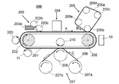
図1、図2は、本実施形態の転写型インクジェット記録装置の概略構成の一例を示す模式図である。 1 and 2 are schematic diagrams illustrating an example of a schematic configuration of a transfer type inkjet recording apparatus according to the present embodiment.
本実施形態の転写型インクジェット記録装置100は、図1に示すように、支持部材102によって支持された転写体101と、転写体101上に反応液を付与する反応液付与装置103と、反応液が付与された転写体101上にインクを付与し転写体上でインク像(第一の画像)を形成するインク付与装置104と、転写体上の第一の画像から液体成分を吸収する液吸収装置105と、記録媒体を押圧することによって液体成分が除去された転写体上の第二の画像を紙などの記録媒体108上に転写する転写用の押圧部材106と、を有する。また、転写型インクジェット記録装置100は、第二の画像を記録媒体108に転写した後の転写体101の表面をクリーニングする転写体クリーニング部材109を有していてもよい。
As shown in FIG. 1, the transfer type
図2は、ベルト形状の転写体201に変更した転写型インクジェット記録装置200を示している。反応液付与装置203、インク付与装置204、第一の画像に含まれる液体成分を吸収する液吸収装置205、転写用の押圧部材206、記録媒体208の搬送装置207は、図1のものと同様の構成を有しており、説明を省略する。
FIG. 2 shows a transfer type ink
なお、ベルト形状の転写体201は、ドラム形状の転写体101に対し、熱容量がすくなくなり、温度の上下制御をおこないやすいため、好ましい。210は転写体201を転写用の押圧部材206側に押し当てる対向ローラを示す。対向ローラ210は加熱部材10を兼ねることができる。転写位置は、図2の位置に限定されず、加熱部材10と対向する支持部材202を対向ローラとして転写してもよい。その他は、図1とほぼ同様であるので、以下、図1について説明する。
Note that the belt-shaped
支持部材102の回転軸102aを中心として図1の矢印Aの方向に回転する。この支持部材102の回転により、転写体101が移動される。移動される転写体101上には、反応液付与装置103による反応液、および、インク付与装置104によるインクが順次付与され、転写体101上に第一の画像が形成される。転写体101上に形成された第一の画像は、転写体101の移動により、液吸収装置105が有する液吸収部材105aと接触する位置まで移動される。
The
液吸収装置105の液吸収部材105aは、転写体101の回転に同期して移動する。転写体101上に形成された画像はこの移動する液吸収部材105aと接触した状態を経る。この間に液吸収部材105aは画像から液体成分を除去する。なお、この液吸収部材105aと接触した状態を経ることで、第一の画像に含まれる液体成分が除かれるが、この接触した状態において、液吸収部材105aは、所定の押圧力をもって第一の画像に押圧されることが、液吸収部材105aを効果的に機能させる点で好ましい構成である。
The
液体成分の除去を異なる視点で説明すれば、転写体上に形成された画像を構成するインクを濃縮するとも表現することができる。インクを濃縮するとは、インクに含まれる液体成分が減少することによって、インクに含まれる色材や樹脂といった固形分の液体成分に対する含有割合が増加することを意味する。 If the removal of the liquid component is described from a different point of view, it can also be expressed as concentrating the ink constituting the image formed on the transfer body. Concentrating the ink means that the content ratio of the solid component such as a coloring material or resin contained in the ink increases as the liquid component contained in the ink decreases.
そして、液体成分が除去された後の第二の画像は、転写体101の移動により、加熱部に移動され、そこで加熱部材10で加熱される。加熱された第二の画像は、記録媒体搬送装置107によって搬送される記録媒体と接触する転写部に移動される。加熱された後の第二の画像が記録媒体108と接触している間に、押圧部材106が記録媒体を押圧することによって、記録媒体108上にインク像が形成される。記録媒体108上に転写された転写後のインク像は第二の画像の反転画像である。以降の説明では、上述した第一の画像(液除去前インク像)、第二の画像(液除去後インク像)とは別に、この転写後インク像を第三の画像ということがある。
Then, the second image after the liquid component is removed is moved to the heating unit by the movement of the
なお、転写体上には反応液が付与されてからインクが付与されて画像が形成されるため、非画像領域(非インク像形成領域)には反応液がインクと反応することなく残っている。本装置では液吸収部材105aは画像からのみならず、未反応の反応液とも接触(圧接)し、反応液の液体成分も併せて転写体101の表面上から除去している。
Since an image is formed by applying ink after the reaction liquid is applied on the transfer body, the reaction liquid remains in the non-image area (non-ink image forming area) without reacting with the ink. . In this apparatus, the
したがって、以上では、画像から液体成分を除去すると表現し説明しているが、画像のみから液体成分を除去するという限定的な意味合いではなく、少なくとも転写体上の画像から液体成分を除去していればよいという意味合いで用いている。例えば、第一の画像とともに第一の画像の外側領域に付与された反応液中の液体成分を除去することも可能である。なお、液体成分は、一定の形を持たず、流動性を有し、ほぼ一定の体積を有するものであれば、特に限定されるものではない。例えば、インクや反応液に含まれる水や有機溶媒等が液体成分として挙げられる。 Therefore, in the above, it is expressed and described that the liquid component is removed from the image, but this is not a limited meaning of removing the liquid component only from the image, and at least the liquid component is removed from the image on the transfer body. It is used in the sense that it should be. For example, it is also possible to remove the liquid component in the reaction solution applied to the outer region of the first image together with the first image. The liquid component is not particularly limited as long as it does not have a certain shape, has fluidity, and has a substantially constant volume. For example, water, an organic solvent, or the like contained in ink or a reaction liquid can be used as the liquid component.
また、上述したクリアインクが第一の画像に含まれている場合においても、液吸収処理によるインクの濃縮を行うことができる。例えば、転写体101上に付与された色材を含有するカラーインクの上にクリアインクが付与された場合、第一の画像の表面には全面的にクリアインクが存在する、若しくは、第一の画像の表面の一箇所または複数箇所にクリアインクが部分的に存在し、他の箇所にはカラーインクが存在する。第一の画像において、カラーインク上にクリアインクが存在している箇所では、多孔質体が第一の画像の表面のクリアインクの液体成分を吸収し、クリアインクの液体成分が移動する。それに伴ってカラーインク中の液体成分が多孔質体側へ移動することで、カラーインク中の水性液体成分が吸収される。
Even when the above-described clear ink is included in the first image, the ink can be concentrated by the liquid absorption process. For example, when the clear ink is applied on the color ink containing the color material applied on the
一方、第一の画像の表面においてクリアインクとカラーインクとが存在している箇所では、カラーインク及びクリアインクのそれぞれの液体成分が多孔質体側へ移動することで液体成分が吸収される。なお、このクリアインクには、転写体101から記録媒体への画像の転写性を向上させるための成分を多く含ませておいてもよい。例えばカラーインクよりも加熱により記録媒体への粘着性が高くなる成分の含有率を高くしておくことが挙げられる。
On the other hand, in the location where the clear ink and the color ink exist on the surface of the first image, the liquid components of the color ink and the clear ink move to the porous body side, and the liquid components are absorbed. The clear ink may contain many components for improving the transferability of the image from the
本実施形態の転写型インクジェット記録装置の各構成について以下に説明する。 Each configuration of the transfer type inkjet recording apparatus of this embodiment will be described below.
<転写体>
転写体101は、上記の通り表面層と圧縮層との間に弾性層を有するものを使用し、図1の転写体101は、下記の支持部材102にて支持されたドラム形状のものである。
<Transfer>
As described above, the
<支持部材>
転写体101は、支持部材102上に支持されている。転写体の支持方法として、各種接着剤や両面テープを用いてもよい。または、転写体に金属、セラミック、樹脂等を材質とした設置用部材を取り付けることで、設置用部材を用いて転写体を支持部材102上に支持してもよい。
<Supporting member>
The
支持部材102は、その搬送精度や耐久性の観点からある程度の構造強度が求められる。支持部材の材質には金属、セラミック、樹脂等が好ましく用いられる。中でも特に、転写時の加圧に耐え得る剛性や寸法精度のほか、動作時のイナーシャを軽減して制御の応答性を向上するために、アルミニウム、鉄、ステンレス、アセタール樹脂、エポキシ樹脂、ポリイミド、ポリエチレン、ポリエチレンテレフタレート、ナイロン、ポリウレタン、シリカセラミクス、アルミナセラミクスが好ましく用いられる。またこれらを組み合わせて用いるのも好ましい。
The
<反応液付与装置>
本実施形態のインクジェット記録装置は、転写体101に反応液を付与する反応液付与装置103を有する。図1の反応液付与装置103は、反応液を収容する反応液収容部103aと、反応液収容部103aにある反応液を転写体101上に付与する反応液付与部材103b、103cを有するグラビアオフセットローラの場合を示している。
<Reaction solution applying apparatus>
The ink jet recording apparatus according to the present embodiment includes a reaction
<インク付与装置>
本実施形態のインクジェット記録装置は、反応液を付与された転写体101にインクを付与するインク付与装置104を有する。反応液とインクとが混合されることで第一の画像が形成され、次の液吸収装置105にて第一の画像から液体成分が吸収される。
<Ink application device>
The ink jet recording apparatus according to this embodiment includes an
<液吸収装置>
本実施形態において、液吸収装置105は、液吸収部材105a、および、液吸収部材105aを転写体101上の第一の画像に押し当てる液吸収用の押圧部材105bを有する。なお、液吸収部材105aおよび押圧部材105bの形状については特に制限がない。例えば、図1に示すように、押圧部材105bが円柱形状であり、液吸収部材105aがベルト形状であって、円柱形状の押圧部材105bでベルト形状の液吸収部材105aを転写体101に押し当てる構成であってもよい。また、押圧部材105bが円柱形状であり、液吸収部材105aが円柱形状の押圧部材105bの周面上に形成された円筒形状であって、円柱形状の押圧部材105bで円筒形状の液吸収部材105aを転写体に押し当てる構成であってもよい。
<Liquid absorption device>
In the present embodiment, the liquid absorbing
本実施形態において、インクジェット記録装置内でのスペース等を考慮すると、液吸収部材105aはベルト形状であることが好ましい。また、このようなベルト形状の液吸収部材105aを有する液吸収装置105は、液吸収部材105aを張架する張架部材を有していてもよい。図1において、105c、105d、105eは張架部材としての張架ローラである。図1において、押圧部材105bも張架ローラと同様に回転するローラ部材としているが、これに限定されるものではない。
In the present embodiment, the
液吸収装置105では、多孔質体を有する液吸収部材105aを押圧部材105bによって第一の画像に押圧させることで、第一の画像に含まれる液体分を液吸収部材105aに吸収させ、第一の画像から液体成分を減少させた第二の画像とする。
In the liquid absorbing
以下、液吸収装置105における、各種条件と構成について詳細に述べる。
Hereinafter, various conditions and configurations in the liquid absorbing
(前処理)
本実施形態において、多孔質体を有する液吸収部材105aを第一の画像に接触させる前に、液吸収部材に湿潤液を付与する前処理手段(図1および2では不図示)によって前処理を施すことが好ましい。本実施形態に用いる湿潤液は、水及び水溶性有機溶剤を含有することが好ましい。水は、イオン交換等により脱イオンした水であることが好ましい。また、水溶性有機溶剤の種類は特に限定されず、エタノールやイソプロピルアルコール等の公知の有機溶剤をいずれも用いる事ができる。本実施形態に用いる液吸収部材の前処理において、多孔質体への湿潤液の付与方法は特に限定されないが、浸漬や液滴滴下が好ましい。
(Preprocessing)
In this embodiment, before the
(加圧条件)
転写体上の第一の画像に対して押圧する液吸収部材の圧力が2.9N/cm2(0.3kgf/cm2)以上であれば、第一の画像中の液体成分をより短時間に固液分離でき、第一の画像中から液体成分を除去できるため好ましい。尚、本明細書における液吸収部材の圧力とは、転写体と液吸収部材との間のニップ圧を示しており、面圧分布測定器(新田株式会社製 I−SCAN)にて面圧測定を行い、加圧領域における加重を面積で割り、値を算出したものである。
(Pressure condition)
When the pressure of the liquid absorbing member that presses against the first image on the transfer body is 2.9 N / cm 2 (0.3 kgf / cm 2 ) or more, the liquid component in the first image is reduced in a shorter time. It is preferable because the liquid component can be removed from the first image. In addition, the pressure of the liquid absorbing member in this specification indicates the nip pressure between the transfer member and the liquid absorbing member, and the surface pressure is measured by a surface pressure distribution measuring instrument (I-SCAN manufactured by Nitta Co., Ltd.). Measurement is performed, and the weight in the pressurization region is divided by the area to calculate the value.
(作用時間)
第一の画像に液吸収部材105aを接触させる作用時間は、第一の画像中の色材が液吸収部材へ付着することをより抑制するために、50ms(ミリ秒)以内であることが好ましい。尚、本明細書における作用時間とは、上述した面圧測定における、転写体の移動方向における圧力感知幅を、転写体の移動速度で割って算出される。以降、この作用時間を液吸収ニップ時間と称す。
(Action time)
The working time for bringing the
このようにして、転写体101上には、第一の画像から液体分が吸収され、液体分の減少した第二の画像が形成される。第二の画像は次に加熱部材10で加熱され、転写部において記録媒体108上に転写される。
In this way, on the
転写時の装置構成及び条件について説明する。 The apparatus configuration and conditions during transfer will be described.
<加熱部材>
本実施形態における加熱部材10としては、赤外線ヒータを用い、非接触式の温度測定装置(不図示)にて、第二の画像の表面温度を測定し、所定の温度になるようにヒータのオンオフを調整する。図1,2では転写体の外部に加熱部材10を設けているが、後述する転写用の押圧部材の内部に加熱手段を含む形態等、転写と同時に加熱してもよい。
<Heating member>
As the
<転写用の押圧部材>
本実施形態では、加熱後の第二の画像と記録媒体搬送装置107によって搬送される記録媒体108とが接触している間に、転写用の押圧部材106が記録媒体108を押圧することによって、記録媒体108上にインク像が転写される。転写体101上の第一の画像に含まれる液体成分を除去した後に、記録媒体108へ転写することにより、カールや、コックリング等を抑制した記録画像を得ることが可能となる。
<Pressing member for transfer>
In the present embodiment, the
押圧部材106は記録媒体108の搬送精度や耐久性の観点からある程度の構造強度が求められる。押圧部材106の材質には金属、セラミック、樹脂等が好ましく用いられる。中でも特に、転写時の加圧に耐え得る剛性や寸法精度のほか、動作時のイナーシャを軽減して制御の応答性を向上するために、アルミニウム、鉄、ステンレス、アセタール樹脂、エポキシ樹脂、ポリイミド、ポリエチレン、ポリエチレンテレフタレート、ナイロン、ポリウレタン、シリカセラミクス、アルミナセラミクスが好ましく用いられる。またこれらを組み合わせて用いてもよい。
The pressing
転写体101上の第二の画像を記録媒体108に転写するために押圧部材106が押圧する時間については特に制限はないが、転写が良好に行われ、かつ転写体の耐久性を損なわないようにするために、5ms以上100ms以下であることが好ましい。尚、本実施形態における押圧する時間とは、記録媒体108と転写体101間が接触している時間を示しており、面圧分布測定器(新田株式会社製 I−SCAN)にて面圧測定を行い、加圧領域の搬送方向長さを搬送速度で割り、値を算出したものである。
There is no particular limitation on the time for the
また、転写体101上の第二の画像を記録媒体108に転写するために押圧部材106が押圧する圧力についても特に制限はないが、転写が良好に行われ、かつ転写体の耐久性を損なわないようにする。このために、圧力が9.8N/cm2(1kg/cm2)以上294.2N/cm2(30kg/cm2)以下であることが好ましい。尚、本実施形態における圧力とは、記録媒体108と転写体101間のニップ圧を示しており、面圧分布測定器により面圧測定を行い、加圧領域における加重を面積で割って、値を算出したものである。
Further, there is no particular limitation on the pressure that the
転写体101上の第二の画像を記録媒体108に転写するために押圧部材106が押圧しているときの温度についても特に制限はないが、インクに含まれる樹脂成分のガラス転移点以上又は軟化点以上であることが好ましい。また、加熱には転写体101上の第二の画像を加熱する加熱部材10、転写体101及び記録媒体108を加熱する加熱手段を備える態様が好ましい。押圧部材106の形状については特に制限されないが、例えばローラ形状のものが挙げられる。
The temperature at which the
<記録媒体および記録媒体搬送装置>
本実施形態において、記録媒体108は特に限定されず、公知の記録媒体をいずれも用いることができる。記録媒体としては、ロール状に巻回された長尺物、あるいは所定の寸法に裁断された枚葉のものが挙げられる。材質としては、紙、プラスチックフィルム、木板、段ボール、金属フィルムなどが挙げられる。また、図1において、記録媒体108を搬送するための記録媒体搬送装置107は、記録媒体繰り出しローラ107aおよび記録媒体巻き取りローラ107bによって構成されているが、記録媒体を搬送できればよく、特にこの構成に限定されるものではない。
<Recording medium and recording medium conveying apparatus>
In the present embodiment, the
<転写体の冷却>
本実施形態では、繰り返し画像形成、液吸収、転写を行うため、転写した後の転写体101を冷却する冷却部材11を有することが好ましい。前記転写工程の後から、前記第一の画像を形成する工程の前までの間に、冷却部材によって転写体を冷却することによって、次に再度第一の画像を形成する工程の後から液体除去工程の間に、画像から液体分が蒸発することを抑制することが可能となる。冷却は、液体除去工程が行われるタイミングにおいて、画像がインク中の水の沸点未満になるように制御する。また、インクが付与されるタイミングにおいて、インク中の水の沸点未満となることがより好ましい。また、図1では転写工程の後に冷却工程を有しているが、インク付与工程の後に設けても構わない。また、図示はしないが、複数冷却する工程を設けることも好ましい。
<Cooling of transfer body>
In this embodiment, in order to repeatedly perform image formation, liquid absorption, and transfer, it is preferable to have a cooling
また、転写体の温度は、反応液に含まれる界面活性剤の曇点未満にまで冷却することが好ましい。反応液を付与する工程において、前記曇点よりも転写体の温度が低いことで、反応液に含まれる界面活性剤の活性能が維持され反応液のぬれ性が十分高くなり、より画像の凝集力が高まると推測される。画像の凝集力が高まることにより、転写性が向上すると考えられる。なお、本発明において、界面活性剤の曇点は界面活性剤の1質量%水溶液を加熱することで測定可能である。 Moreover, it is preferable to cool the temperature of the transfer body to less than the cloud point of the surfactant contained in the reaction solution. In the step of applying the reaction solution, the temperature of the transfer body is lower than the cloud point, so that the activity of the surfactant contained in the reaction solution is maintained, the wettability of the reaction solution is sufficiently high, and the image is more aggregated. It is estimated that power will increase. It is considered that the transferability is improved by increasing the cohesive force of the image. In the present invention, the cloud point of the surfactant can be measured by heating a 1% by weight aqueous solution of the surfactant.
冷却方法としては、冷風を吹きつける方法、冷却したローラを接触させる方法、冷却された液体を付与する方法、気化熱を利用した方法等、公知の方法を用いることが可能である。特に高速に冷却するために、固体、もしくは液体を転写体に接触させる方法を用いることが好ましい。この固体及び液体は、水の沸点未満に冷却されているものである。さらに送風等を組み合わせることも好ましい。液体を接触させる方法としては、液体を直接付与してもよいし、多孔質体に含ませて接触させてもよい。また、液吸収部材105aを冷却することで、液体除去工程においても、より確実に第一の画像中の液体成分の蒸発を抑制し、吸収不良を防止することが可能となる。
As a cooling method, a known method such as a method of blowing cold air, a method of bringing a cooled roller into contact, a method of applying a cooled liquid, a method using heat of vaporization, or the like can be used. In particular, in order to cool at high speed, it is preferable to use a method in which a solid or a liquid is brought into contact with the transfer body. These solids and liquids are those that are cooled below the boiling point of water. Further, it is also preferable to combine air blowing or the like. As a method of bringing the liquid into contact, the liquid may be directly applied, or the liquid may be included in contact with the porous body. In addition, by cooling the
<クリーニング部材>
本実施形態では、転写した後の転写体に残った画像や、記録媒体から転写した紙粉等をクリーニングするクリーニング部材109を用いてもよい。クリーニングは多孔質部材を接触させる方式、ブラシで擦る方式、ブレードでかきとる方式等の公知の方式を適宜用いることができる。また、部材の形状もローラ形状、ウェブ形状等、公知の形状を用いることができる。本発明では、クリーニング部材の温度を冷却することによって、前述した冷却部材と兼ねることも好ましい。
<Cleaning member>
In the present embodiment, a cleaning
<制御システム>
本実施形態における転写型インクジェット記録装置は、各装置を制御する制御システムを有する。図3は図1に示す転写型インクジェット記録装置における、装置全体の制御システムを示すブロック図である。
<Control system>
The transfer type inkjet recording apparatus in the present embodiment has a control system that controls each apparatus. FIG. 3 is a block diagram showing a control system of the entire apparatus in the transfer type ink jet recording apparatus shown in FIG.
図3において、301は外部プリントサーバー等の記録データ生成部、302は操作パネル等の操作制御部、303は記録プロセスを実施するためのプリンタ制御部、304は記録媒体を搬送するための記録媒体搬送制御部、305は印刷するためのインクジェットデバイスである。
In FIG. 3, 301 is a recording data generation unit such as an external print server, 302 is an operation control unit such as an operation panel, 303 is a printer control unit for executing a recording process, and 304 is a recording medium for conveying the recording medium. A
図4は図1の転写型インクジェット記録装置におけるプリンタ制御部のブロック図である。401はプリンタ全体を制御するCPU、402は前記CPUの制御プログラムを格納するためのROM、403はプログラムを実行するためのRAMである。404はネットワークコントローラ、シリアルIFコントローラ、ヘッドデータ生成用コントローラ、モーターコントローラ等を内蔵したASICである。405は液吸収部材搬送モータ406を駆動するための液吸収部材搬送制御部であり、404のASICからシリアルIFを介して、コマンド制御される。407は転写体駆動モータ408を駆動するための転写体駆動制御部であり、同様に404のASICからシリアルIFを介してコマンド制御される。409はヘッド制御部であり、インクジェットデバイス305の最終吐出データ生成、駆動電圧生成等を行う。また、410は転写体温度制御部であり、加熱部材10、冷却部材11の温度制御を行う。
FIG. 4 is a block diagram of a printer control unit in the transfer type inkjet recording apparatus of FIG. A
以下、実施例及び比較例を用いて本発明を更に詳細に説明する。本発明は、その要旨を超えない限り、下記の実施例によって何ら限定されるものではない。尚、以下の実施例の記載において、「部」とあるのは特に断りのない限り質量基準である。 Hereinafter, the present invention will be described in more detail with reference to Examples and Comparative Examples. The present invention is not limited in any way by the following examples as long as the gist thereof is not exceeded. In the description of the following examples, “part” is based on mass unless otherwise specified.
本実施例は図1に示す転写型インクジェット記録装置を用いた。
本実施例における転写体101は接着剤により支持部材102に固定されている。本実施例では、厚さ0.5mmのPETシートにシリコーンゴム(信越化学工業株式会社製KE12)を0.3mmの厚さにコーティングしたシートを転写体Jの弾性層として用いた。さらにグリシドキシプロピルトリエトキシシランとメチルトリエトキシシランとをモル比1:1で混合し、加熱還流により得られる縮合物と光カチオン重合開始剤(ADEKA製SP150)の混合物を作製した。弾性層表面の水の接触角が10度以下となるように大気圧プラズマ処理を行い、前記混合物を弾性層上に付与し、UV照射(高圧水銀ランプ、積算露光量5000mJ/cm2)、熱硬化(150℃2時間)により成膜し、弾性体上に厚さ0.5μmの表面層を形成した転写体101を作製した。なお、本構成においては、説明の簡略のため図示を省略しているが、転写体101と支持部材102の間に転写体101を保持するために両面テープを用いた。
In this example, the transfer type ink jet recording apparatus shown in FIG. 1 was used.
The
反応液付与装置103により付与される反応液は、下記組成のものを用い、付与量は1g/m2とした。下記反応液中の界面活性剤の曇点は50℃であった。なお、界面活性剤の曇点は、界面活性剤の1質量%水溶液を加熱することで測定した。
・グルタル酸 21.0部
・水酸化カリウム 2.0部
・グリセリン 5.0部
・界面活性剤(製品名:TF−2066、DIC株式会社製) 5.0部
・イオン交換水 残部
The reaction liquid applied by the reaction
・ Glutaric acid 21.0 parts ・ Potassium hydroxide 2.0 parts ・ Glycerin 5.0 parts ・ Surfactant (product name: TF-2066, manufactured by DIC Corporation) 5.0 parts ・ Ion-exchanged water remaining
インクは以下のように調製した。 The ink was prepared as follows.
<顔料分散体の調製>
カーボンブラック(製品名:モナク1100、キャボット製)10部、樹脂水溶液1(スチレン−アクリル酸エチル−アクリル酸共重合体、酸価150、重量平均分子量(Mw)8,000、樹脂の含有量が20.0質量%の水溶液を水酸化カリウム水溶液で中和したもの)15部、純水75部を混合し、バッチ式縦型サンドミル(アイメックス製)に仕込み、0.3mm径のジルコニアビーズを200部充填し、水冷しつつ、5時間分散処理を行った。この分散液を遠心分離して、粗大粒子を除去した後、顔料の含有量が10.0質量%のブラック顔料分散体を得た。
<Preparation of pigment dispersion>
10 parts of carbon black (product name: Monac 1100, manufactured by Cabot), aqueous resin solution 1 (styrene-ethyl acrylate-acrylic acid copolymer, acid value 150, weight average molecular weight (Mw) 8,000, resin content is 15 parts of a 20.0% by weight aqueous solution neutralized with a potassium hydroxide aqueous solution) and 75 parts of pure water were mixed and charged into a batch type vertical sand mill (manufactured by IMEX). The dispersion treatment was carried out for 5 hours while partly filling and cooling with water. This dispersion was centrifuged to remove coarse particles, and then a black pigment dispersion having a pigment content of 10.0% by mass was obtained.
<樹脂微粒子分散体の調製>
(樹脂微粒子分散体1の調製)
エチルメタクリレート18%、2,2’−アゾビス−(2−メチルブチロニトリル)2%、n−ヘキサデカン2%を混合し、0.5時間攪拌した。この混合物を、乳化剤である「NIKKOL BC15」(商品名、日光ケミカルズ社製)の6%水溶液(配合割合78%)に滴下して、0.5時間攪拌した。次に超音波照射機で超音波を3時間照射した。続いて、窒素雰囲気下で80℃、4時間重合反応を行い、室温冷却後にろ過して、樹脂の含有量が25.0質量%である樹脂微粒子分散体1を調製した。
<Preparation of resin fine particle dispersion>
(Preparation of resin fine particle dispersion 1)
Ethyl methacrylate 18%, 2,2′-azobis- (2-methylbutyronitrile) 2%, and n-hexadecane 2% were mixed and stirred for 0.5 hour. This mixture was added dropwise to a 6% aqueous solution (mixing ratio 78%) of “NIKKOL BC15” (trade name, manufactured by Nikko Chemicals), which is an emulsifier, and stirred for 0.5 hour. Next, the ultrasonic wave was irradiated for 3 hours with the ultrasonic irradiation machine. Subsequently, a polymerization reaction was performed in a nitrogen atmosphere at 80 ° C. for 4 hours, followed by cooling after room temperature cooling to prepare resin fine particle dispersion 1 having a resin content of 25.0% by mass.
<インク1の調製>
上記で得られた樹脂微粒子分散体1、及び、顔料分散体を下記各成分と混合し、インク1を調製した。尚、イオン交換水の残部は、インクを構成する全成分の合計が100.0質量%となる量のことである。
<Preparation of ink 1>
The resin fine particle dispersion 1 and the pigment dispersion obtained above were mixed with the following components to prepare ink 1. The balance of ion-exchanged water is such that the total of all components constituting the ink is 100.0% by mass.
・顔料分散体(色材の含有量は10.0質量%) 40.0質量%
・樹脂微粒子分散体1 20.0質量%
・グリセリン 7.0質量%
・ポリエチレングリコール(数平均分子量(Mn):1,000) 3.0質量%
・界面活性剤 0.5質量%
(商品名:アセチレノールE100、川研ファインケミカル株式会社製)
・イオン交換水 残部
Pigment dispersion (coloring material content is 10.0% by mass) 40.0% by mass
・ Resin fine particle dispersion 1 20.0 mass%
・ Glycerin 7.0% by mass
Polyethylene glycol (number average molecular weight (Mn): 1,000) 3.0% by mass
・ Surfactant 0.5% by mass
(Product name: Acetylenol E100, manufactured by Kawaken Fine Chemical Co., Ltd.)
・ Ion exchange water balance
これを十分撹拌して分散した後、ポアサイズ3.0μmのミクロフィルター(富士フイルム株式会社製)にて加圧ろ過を行い、インク1を調製した。このインク1の最低造膜温度(MFT)は100℃であった。最低造膜温度(MFT)の測定は、インクを常温で24時間乾燥させた後のサンプルを用いて、膜化する温度を評価した。 After sufficiently stirring and dispersing this, pressure filtration was performed with a microfilter (manufactured by Fuji Film Co., Ltd.) having a pore size of 3.0 μm to prepare ink 1. The minimum film forming temperature (MFT) of this ink 1 was 100 ° C. For the measurement of the minimum film-forming temperature (MFT), the temperature at which a film was formed was evaluated using a sample after the ink was dried at room temperature for 24 hours.
<インク2の調製>
ポリエチレンワックス(商品名「ハイワックス100P」、三井化学株式会社製)10部、樹脂水溶液1を125部、及びイオン交換水65部をホモミキサーで0.5時間予備混合して混合物を得た。得られた混合物を、加熱オプションにて120℃に加熱した高圧ホモジナイザー(商品名「ナノヴェイタ」、吉田機械興業製)に3回通して、ワックス粒子分散体1を得た。動的光散乱式粒子径分布測定装置(商品名「Microtrack UPA EX−150」、日機装製)を使用して測定したワックスの体積平均の分散粒子径は、120nmであった。
<Preparation of ink 2>
A mixture was obtained by premixing 10 parts of polyethylene wax (trade name “High Wax 100P”, manufactured by Mitsui Chemicals, Inc.), 125 parts of the aqueous resin solution 1, and 65 parts of ion-exchanged water with a homomixer for 0.5 hours. The obtained mixture was passed three times through a high-pressure homogenizer (trade name “Nanovaita”, manufactured by Yoshida Kikai Kogyo Co., Ltd.) heated to 120 ° C. with a heating option to obtain wax particle dispersion 1. The volume average dispersed particle size of the wax measured using a dynamic light scattering type particle size distribution measuring device (trade name “Microtrack UPA EX-150”, manufactured by Nikkiso) was 120 nm.
インク1と同様にワックス粒子分散体1を用いて、以下のインク2を調製した。
(インク2)
・顔料分散体(色材の含有量は10.0質量%) 40.0質量%
・樹脂微粒子分散体1 15.0質量%
・ワックス粒子分散体1 5.0質量%
・グリセリン 7.0質量%
・ポリエチレングリコール(数平均分子量(Mn):1,000) 3.0質量%
・界面活性剤 0.5質量%
(商品名:アセチレノールE100、川研ファインケミカル株式会社製)
・イオン交換水 残部
インク2の最低造膜温度(MFT)は110℃であった。
The following ink 2 was prepared using the wax particle dispersion 1 in the same manner as the ink 1.
(Ink 2)
Pigment dispersion (coloring material content is 10.0% by mass) 40.0% by mass
・ Resin fine particle dispersion 1 15.0 mass%
-Wax particle dispersion 1 5.0% by mass
・ Glycerin 7.0% by mass
Polyethylene glycol (number average molecular weight (Mn): 1,000) 3.0% by mass
・ Surfactant 0.5% by mass
(Product name: Acetylenol E100, manufactured by Kawaken Fine Chemical Co., Ltd.)
-Ion exchange water remainder The minimum film forming temperature (MFT) of the ink 2 was 110 degreeC.
<インク3の調製>
(樹脂微粒子分散体2の調製)
ブチルメタクリレート18%、2,2’−アゾビス−(2−メチルブチロニトリル)2%、n−ヘキサデカン2%を混合し、0.5時間攪拌した。この混合物を、乳化剤である「NIKKOL BC15」(商品名、日光ケミカルズ社製)の6%水溶液(配合割合78%)に滴下して、0.5時間攪拌した。次に超音波照射機で超音波を3時間照射した。続いて、窒素雰囲気下で80℃、4時間重合反応を行い、室温冷却後にろ過して、樹脂の含有量が25.0質量%である樹脂微粒子分散体2を調製した。
<Preparation of ink 3>
(Preparation of resin fine particle dispersion 2)
Butyl methacrylate 18%, 2,2′-azobis- (2-methylbutyronitrile) 2%, n-hexadecane 2% were mixed and stirred for 0.5 hour. This mixture was added dropwise to a 6% aqueous solution (mixing ratio 78%) of “NIKKOL BC15” (trade name, manufactured by Nikko Chemicals), which is an emulsifier, and stirred for 0.5 hour. Next, the ultrasonic wave was irradiated for 3 hours with the ultrasonic irradiation machine. Subsequently, a polymerization reaction was performed in a nitrogen atmosphere at 80 ° C. for 4 hours, followed by cooling after room temperature cooling to prepare resin fine particle dispersion 2 having a resin content of 25.0% by mass.
上記で得られた樹脂微粒子分散体2、及び、顔料分散体を下記各成分と混合し、インク3を調製した。尚、イオン交換水の残部は、インクを構成する全成分の合計が100.0質量%となる量のことである。 The resin fine particle dispersion 2 and the pigment dispersion obtained above were mixed with the following components to prepare ink 3. The balance of ion-exchanged water is such that the total of all components constituting the ink is 100.0% by mass.
・顔料分散体(色材の含有量は10.0質量%) 40.0質量%
・樹脂微粒子分散体2 20.0質量%
・グリセリン 7.0質量%
・ポリエチレングリコール(数平均分子量(Mn):1,000) 3.0質量%
・界面活性剤 0.5質量%
(商品名:アセチレノールE100、川研ファインケミカル株式会社製)
・イオン交換水 残部
Pigment dispersion (coloring material content is 10.0% by mass) 40.0% by mass
・ Resin fine particle dispersion 2 20.0 mass%
・ Glycerin 7.0% by mass
Polyethylene glycol (number average molecular weight (Mn): 1,000) 3.0% by mass
・ Surfactant 0.5% by mass
(Product name: Acetylenol E100, manufactured by Kawaken Fine Chemical Co., Ltd.)
・ Ion exchange water balance
これを十分撹拌して分散した後、ポアサイズ3.0μmのミクロフィルター(富士フイルム株式会社製)にて加圧ろ過を行い、インク3を調製した。このインク3の最低造膜温度(MFT)は50℃であった。 After sufficiently stirring and dispersing, ink 3 was prepared by performing pressure filtration with a micro filter (manufactured by Fuji Film Co., Ltd.) having a pore size of 3.0 μm. The minimum film forming temperature (MFT) of this ink 3 was 50 ° C.
インク付与装置104は電気−熱変換素子を用いオンデマンド方式にてインク吐出を行うタイプのインクジェットヘッドを使用し、インク付与量は20g/m2とした。液吸収部材105aは液吸収部材を張架しつつ搬送する搬送ローラ105c、105d、105eによって、転写体101の移動速度と同等の速度になるよう調節されている。また、転写体101の移動速度と同等の速度となるように、記録媒体108は記録媒体繰り出しローラ107aおよび記録媒体巻き取りローラ107bによって搬送される。本実施例において、搬送速度は0.1m/sとし、記録媒体108としてオーロラコート紙(日本製紙株式会社製・坪量104g/m2)を用いた。転写体上の画像は29.4N/cm2(3kg/cm2)の圧力にて記録媒体へ転写した。
The
また、転写体101と液吸収部材105aとの間のニップ圧は、平均圧力が29.4N/cm2(3kg/cm2)となるよう液吸収部材105bに圧力が印加されている。また、液吸収装置105における押圧部材105bはローラ直径φ400mmのものを用いた。液吸収部材105aは、平均孔径0.2μmの親水PTFEを用いた。この吸収部材のガーレは8秒であった。
The nip pressure between the
また、加熱部材10にはヘレウス株式会社製の赤外線ヒータを用いた。そして赤外線ヒータへの入力電圧を変えることにより、画像の加熱温度を制御した。また、冷却部材11として、図示しないチラーで冷却した水を含ませた不織布(廣瀬製紙株式会社製 HOP60)を転写体に接触させる方式を用いた。含ませる水の冷却温度を制御することにより、転写体の冷却温度を制御した。インク1〜3と、加熱部材、冷却部材の制御状態を組み合わせることで、以下の表1に示す条件にて、画像の転写性と吸収性能とを評価した。なお、実施例4は実施例1に対し、液吸収部材を70℃未満に冷却制御した。また、表1において、「インク主溶媒の沸点」とは「インク中の水の沸点」のことであり、「画像の最低造膜温度」は、「第二の画像の最低造膜温度」のことである。また、「印字〜液体除去温度」とは、「第一の画像を形成する工程(インクを付与する工程)の後から液体除去工程の前までの間の第一の画像の温度」のことである。なお、本実施例において、反応液中に造膜助剤等、第二の画像の最低造膜温度に影響を与える成分が含まれていないため、インクの最低造膜温度を、第二の画像の最低造膜温度とした。
Further, an infrared heater manufactured by Heraeus Co., Ltd. was used as the

上記表1に示す条件にて評価した評価結果を表2に示す。本発明においては、下記の各評価項目の評価基準のA〜Bを許容レベルとし、Cを許容できないレベルとした。 Table 2 shows the evaluation results evaluated under the conditions shown in Table 1 above. In the present invention, the evaluation criteria A to B of the following evaluation items were set to acceptable levels, and C was set to an unacceptable level.
<転写性>
上述した条件における転写工程による、転写量を示す。転写量が多い(転写しない領域が少ない)ことが好ましく、評価基準は以下の通りである。
A:転写しない画像領域がほぼみられなかった。
B:転写しない画像領域がわずかにみられたが、実用上問題のないレベルであった。
C:転写しない画像領域が大きくみられ、実用上問題であった。
<Transferability>
The transfer amount by the transfer process under the above-described conditions is shown. It is preferable that the transfer amount is large (the number of non-transfer areas is small), and the evaluation criteria are as follows.
A: Almost no image area to be transferred was observed.
B: Although there was a slight image area that was not transferred, it was at a level with no practical problem.
C: The image area which is not transferred was large, which was a problem in practical use.
<堅牢性>
転写体上での液除去性及び画像のMFTに依存する画像の堅牢性を示す。残存液量が多いと画像の堅牢性が低下する場合がある。したがって、残存液量が少ないことが好ましい。また、画像の堅牢性は画像のMFTにも影響を受ける。評価基準は以下の通りである。上述した条件で作製された記録媒体上の画像を25mm幅の短冊状に切断し、学振型試験機である耐摩耗試験機(株式会社井本製作所製)を用いて、短冊状に切断された印刷物と擦過子に同印刷用紙を設置し、荷重500g・200回の摩擦試験を行い、擦過性の評価を行った。
<Robustness>
The liquid removability on the transfer body and the image fastness depending on the MFT of the image are shown. When the amount of the remaining liquid is large, the fastness of the image may be lowered. Therefore, it is preferable that the remaining liquid amount is small. The robustness of the image is also affected by the MFT of the image. The evaluation criteria are as follows. The image on the recording medium produced under the conditions described above was cut into a 25 mm-wide strip and cut into a strip using an abrasion resistance tester (manufactured by Imoto Seisakusho Co., Ltd.), which is a Gakushin type testing machine. The same printing paper was placed on the printed material and the scraper, and a friction test was performed with a load of 500 g and 200 times to evaluate the scratching property.
なお、転写性の評価がCのものは、評価が不可能であるため、評価なし(−)とした。
A:擦過痕がみられない。
B:わずかに擦過痕がみられたが、実用上問題のないレベルであった。
C:擦過痕が大きくみられた。
In addition, since the evaluation of transferability evaluation C was impossible, it was set as no evaluation (-).
A: No scratch mark is observed.
B: A slight scratch mark was observed, but it was a level with no practical problem.
C: Large scratch marks were observed.
10 加熱部材
11 冷却部材
100,200 転写型インクジェット記録装置
101,201 転写体
102,202 支持部材
102a 支持部材の回転軸
103,203 反応液付与装置
103a,203a 反応液収容部
103b、c,203b、c 反応液付与部材
104,204 インク付与装置
105,205 液吸収装置
105a,205a 液吸収部材
105b,205b 押圧部材
105c、d、e,205c、d、e 張架ローラ
106,206 転写用の押圧部材
107,207 記録媒体搬送装置
107a,207a 記録媒体繰り出しローラ
107b,207b 記録媒体巻き取りローラ
108,208 記録媒体
109,209 転写体クリーニング部材
210 対向ローラ
301 記録データ生成部
302 操作制御部
303 プリンタ制御部
304 記録媒体搬送制御部
305 インクジェットデバイス
401 CPU
402 ROM
403 RAM
404 ASIC
405 液吸収部材搬送制御部
406 液吸収部材搬送モータ
407 転写体駆動制御部
408 転写体駆動モータ
409 ヘッド制御部
410 転写体温度制御部
DESCRIPTION OF
402 ROM
403 RAM
404 ASIC
405 Liquid absorbing member
Claims (14)
前記第一の画像の形成された前記転写体に多孔質体を接触させ、前記第一の画像に含まれる液体成分の一部が除去された第二の画像を形成する液体除去工程と、
前記第二の画像を、当該第二の画像の最低造膜温度以上に加熱して記録媒体上に転写する転写工程と、
を前記転写体上で繰り返し行うインクジェット記録方法であって、
前記第二の画像の最低造膜温度が100℃以上の温度であり、
前記第一の画像は、前記第一の画像を形成する工程の後から前記液体除去工程の前までの間に、水の沸点以上の熱履歴を受けないことを特徴とするインクジェット記録方法。 A water-soluble organic solvent having a boiling point higher than that of water and water by passing through a step of applying a reaction liquid containing an ink thickening component and a step of applying an ink containing water and a coloring material on the transfer body; Forming a first image comprising: a liquid component containing a solid component insoluble in the liquid component formed by mixing the reaction liquid and the ink;
A liquid removal step of bringing a porous body into contact with the transfer body on which the first image is formed, and forming a second image in which a part of the liquid component contained in the first image is removed; and
A transfer step in which the second image is heated to a temperature equal to or higher than the minimum film-forming temperature of the second image and transferred onto a recording medium;
Is an ink jet recording method for repeatedly performing on the transfer body,
The minimum film-forming temperature of the second image is a temperature of 100 ° C. or higher,
The inkjet recording method according to claim 1, wherein the first image does not receive a thermal history higher than a boiling point of water between the step of forming the first image and the step of removing the liquid.
前記第一の画像の形成された前記転写体に多孔質体を接触させ、前記第一の画像を構成するインクを濃縮して第二の画像を形成する液体除去工程と、
前記第二の画像を、当該第二の画像の最低造膜温度以上に加熱して記録媒体上に転写する転写工程と、
を前記転写体上で繰り返し行うインクジェット記録方法であって、
前記第二の画像の最低造膜温度が100℃以上の温度であり、
前記第一の画像は、前記第一の画像を形成する工程の後から前記液体除去工程の前までの間に、水の沸点以上の熱履歴を受けないことを特徴とするインクジェット記録方法。 A water-soluble organic solvent having a boiling point higher than that of water and water by passing through a step of applying a reaction liquid containing an ink thickening component and a step of applying an ink containing water and a coloring material on the transfer body; Forming a first image comprising: a liquid component containing a solid component insoluble in the liquid component formed by mixing the reaction liquid and the ink;
A liquid removing step of bringing a porous body into contact with the transfer body on which the first image is formed, and concentrating ink constituting the first image to form a second image;
A transfer step in which the second image is heated to a temperature equal to or higher than the minimum film-forming temperature of the second image and transferred onto a recording medium;
Is an ink jet recording method for repeatedly performing on the transfer body,
The minimum film-forming temperature of the second image is a temperature of 100 ° C. or higher,
The inkjet recording method according to claim 1, wherein the first image does not receive a thermal history higher than a boiling point of water between the step of forming the first image and the step of removing the liquid.
Applications Claiming Priority (2)
| Application Number | Priority Date | Filing Date | Title |
|---|---|---|---|
| JP2016027909 | 2016-02-17 | ||
| JP2016027909 | 2016-02-17 |
Publications (1)
| Publication Number | Publication Date |
|---|---|
| JP2017144736A true JP2017144736A (en) | 2017-08-24 |
Family
ID=59680592
Family Applications (1)
| Application Number | Title | Priority Date | Filing Date |
|---|---|---|---|
| JP2017026933A Pending JP2017144736A (en) | 2016-02-17 | 2017-02-16 | Ink jet recording method |
Country Status (1)
| Country | Link |
|---|---|
| JP (1) | JP2017144736A (en) |
Cited By (1)
| Publication number | Priority date | Publication date | Assignee | Title |
|---|---|---|---|---|
| JP7528537B2 (en) | 2020-05-27 | 2024-08-06 | コニカミノルタ株式会社 | Image forming apparatus and control method |
-
2017
- 2017-02-16 JP JP2017026933A patent/JP2017144736A/en active Pending
Cited By (1)
| Publication number | Priority date | Publication date | Assignee | Title |
|---|---|---|---|---|
| JP7528537B2 (en) | 2020-05-27 | 2024-08-06 | コニカミノルタ株式会社 | Image forming apparatus and control method |
Similar Documents
| Publication | Publication Date | Title |
|---|---|---|
| WO2017119049A1 (en) | Ink jet recording method | |
| JP6862184B2 (en) | Inkjet recording device and inkjet recording method | |
| WO2017119043A1 (en) | Inkjet recording device and inkjet recording method | |
| WO2017119048A1 (en) | Ink jet recording apparatus and ink jet recording method | |
| JP6448673B2 (en) | Porous material and method for producing the same, ink jet recording method, and ink jet recording apparatus | |
| JP2017213856A (en) | Ink-jet recording device an ink-jet recording method | |
| JP6821439B2 (en) | Image forming device and image forming method | |
| JP6840552B2 (en) | Inkjet recording method and inkjet recording device | |
| WO2017119045A1 (en) | Inkjet recording apparatus and method for manufacturing porous body | |
| WO2017119046A1 (en) | Inkjet recording method | |
| JP2017136837A (en) | Inkjet recording device and inkjet recording method | |
| WO2017119047A1 (en) | Recording method and recording apparatus | |
| WO2017141843A1 (en) | Inkjet recording device and inkjet recording method | |
| US10525700B2 (en) | Transfer type ink jet recording method and transfer type ink jet recording apparatus | |
| JP2017144733A (en) | Inkjet recording method and inkjet recording device | |
| JP2020078925A (en) | Ink jet recording method | |
| JP6415610B2 (en) | Recording method and recording apparatus | |
| JP2019010873A (en) | Liquid absorbing body, and liquid removal method, image formation method and image formation apparatus using liquid absorbing body | |
| JP2017144736A (en) | Ink jet recording method | |
| JP2019010831A (en) | Transfer type inkjet recording method and transfer type inkjet recording device | |
| JP2019010756A (en) | Transfer type inkjet recording method, and transfer type inkjet recording device | |
| JP6838973B2 (en) | Method for manufacturing an inkjet recording device and a porous body | |
| JP6869782B2 (en) | Inkjet recording method | |
| JP6849450B2 (en) | Inkjet recording device and inkjet recording method | |
| JP2024046321A (en) | Inkjet recording device and inkjet recording method |