JP2017144683A - Laminate for decorative molding, decorative molding, and method for producing decorative molding - Google Patents
Laminate for decorative molding, decorative molding, and method for producing decorative molding Download PDFInfo
- Publication number
- JP2017144683A JP2017144683A JP2016029650A JP2016029650A JP2017144683A JP 2017144683 A JP2017144683 A JP 2017144683A JP 2016029650 A JP2016029650 A JP 2016029650A JP 2016029650 A JP2016029650 A JP 2016029650A JP 2017144683 A JP2017144683 A JP 2017144683A
- Authority
- JP
- Japan
- Prior art keywords
- laminate
- decorative
- decorative molding
- protective layer
- haze
- Prior art date
- Legal status (The legal status is an assumption and is not a legal conclusion. Google has not performed a legal analysis and makes no representation as to the accuracy of the status listed.)
- Granted
Links
Images


Abstract
Description
本発明は、加飾成形用積層体、加飾成形体及び加飾成形体の製造方法に関する。 The present invention relates to a decorative molded laminate, a decorative molded body, and a method for manufacturing a decorative molded body.
従来、自動車内外装部品、家電用部品、建材用部品などの表面を保護したり、装飾(加飾)をする場合、射出成形や真空成形によって成形体を加工した後、成形体の表面にスプレー塗装などで塗料を塗布し、乾燥・加熱硬化させることが行われていた。しかし、この様な塗装は、揮発性有機溶剤の排出が作業環境を悪化させるという問題に加え、成形部品ごとの作業工程と生産設備が必要となることや、塗料の重ね塗りが必要となるため塗料の歩留りが悪く、生産性が低いという問題があった。 Conventionally, when protecting the surface of automobile interior and exterior parts, parts for home appliances, parts for building materials, etc. or decorating (decorating), after processing the molded body by injection molding or vacuum molding, spray the surface of the molded body Applying paint by painting, etc., drying and heat curing were performed. However, in addition to the problem that the discharge of volatile organic solvents worsens the working environment, such painting requires work processes and production facilities for each molded part, and requires repeated coating of paint. There was a problem that the yield of paint was poor and the productivity was low.
近年は、自動車内外装部品、家電用部品、建材用部品などを軽量化する目的で、成形体として樹脂成形体の使用が進んでいる。樹脂成形体の装飾(加飾)には、スプレー塗装が適さない場合が多く、樹脂成形体の表面を加飾するために、様々な手法が開発されている。中でも、成形体の最表面を、加飾フィルムで加飾して加飾成形体を得る方法は、塗料等を使って表面に塗布又は印刷する方法よりも、意匠の自由度が高く、生産性も優れるといった利点を有する。また、加飾フィルムを用いた加飾方法は、三次元的な凹凸を有する成形体表面も加飾をすることできるため、様々な用途に用いられている。 In recent years, resin molded bodies have been used as molded bodies for the purpose of reducing the weight of automobile interior and exterior parts, household appliance parts, building material parts, and the like. In many cases, spray coating is not suitable for decoration (decoration) of a resin molded body, and various methods have been developed to decorate the surface of the resin molded body. Above all, the method of obtaining the decorative molded body by decorating the outermost surface of the molded body with a decorative film has higher design freedom and productivity than the method of applying or printing on the surface using a paint or the like. Has the advantage of being excellent. Moreover, since the decorating method using a decorating film can also decorate the molded object surface which has a three-dimensional unevenness | corrugation, it is used for various uses.
加飾フィルムとしては、加飾層のみを有するフィルムや、加飾層と基材層を有するフィルムが知られている。例えば特許文献1及び2には、光硬化樹脂層としてハードコート層を含む加飾フィルムが開示されている。特許文献1においては、ハードコート層に微粒子を含有させることにより、表面にマットな質感を付与している。また、特許文献2においては、ハードコート層の表面に微細エンボス加工を施すことにより、深み感と鮮鋭性に優れた加飾フィルムが得られるとされている。
As a decorative film, a film having only a decorative layer and a film having a decorative layer and a base material layer are known. For example,
ところで、三次元的な凹凸を有する成形体表面を加飾フィルムで加飾する方法としては、3次元被覆成形(TOM成形)方法がある(特許文献3)。TOM成形は真空条件下又は減圧条件下での成形工法であり、加飾フィルムと成形体を圧着させて加飾成形体を得る方法である。TOM成形においては、成形体の材質を問わず加飾をすることが可能である。また、成形体に真空孔を設けることなく、逆テーパ部、末端巻き込み部を被覆成形することができる。 By the way, as a method of decorating the surface of a molded article having three-dimensional irregularities with a decorative film, there is a three-dimensional covering molding (TOM molding) method (Patent Document 3). TOM molding is a molding method under vacuum conditions or reduced pressure conditions, and is a method in which a decorative film and a molded body are pressure-bonded to obtain a decorative molded body. In TOM molding, it is possible to decorate regardless of the material of the molded body. Moreover, a reverse taper part and a terminal winding part can be coat-molded, without providing a vacuum hole in a molded object.
TOM成形に用いられる加飾フィルムとしては、加飾層のみを有するフィルムと、加飾層と粘着層等を有する積層フィルム(積層体)がある。加飾層のみを有するフィルムを用いて加飾成形体を得る場合は、フィルム自体を溶融して、溶融フィルムと成形体を密着させる方法が用いられる。また、加飾層と粘着層を有する積層フィルムを用いる場合は、加飾層は溶融させる必要はなく、粘着層等の粘着力を利用して、積層フィルムと成形体を密着させる。 As a decorative film used for TOM molding, there are a film having only a decorative layer, and a laminated film (laminate) having a decorative layer and an adhesive layer. When obtaining a decorative molded body using a film having only a decorative layer, a method of melting the film itself and bringing the molten film and the molded body into close contact with each other is used. Moreover, when using the laminated | multilayer film which has a decoration layer and an adhesion layer, it is not necessary to fuse a decoration layer, but a laminated film and a molded object are closely_contact | adhered using adhesive force, such as an adhesion layer.
上述したように様々な加飾フィルムが開発されているが、特許文献1及び2においては、加飾フィルムをTOM成形に用いることについては、十分な検討がなされていない。本発明者らが特許文献1に記載されたような加飾フィルムを用いてTOM成形を行った場合、微粒子が存在する位置でクラックが生じ、成形体に沿って十分な延伸性を示さないか、もしくは十分な加飾性能を発揮しないものである(すなわちヘイズ値が低い)ものであることがわかった。また、特許文献2に記載された加飾フィルムは延伸性が十分でなく、TOM成形の用途とする場合には改善の余地が残されていた。
As described above, various decorative films have been developed. However,
そこで本発明者らは、このような従来技術の課題を解決するために、十分な延伸性を発揮でき、かつ延伸前後のヘイズの低下が少ない加飾フィルム(加飾成形用積層体)を提供することを目的として検討を進めた。 Accordingly, the present inventors provide a decorative film (decorative molding laminate) that can exhibit sufficient stretchability and has little decrease in haze before and after stretching in order to solve such problems of the prior art. We proceeded with the study for the purpose of doing this.
上記の課題を解決するために鋭意検討を行った結果、本発明者らは、特定の表面保護層を有する加飾成形用積層体において、表面保護層のヘイズを所定の条件とし、かつ加飾成形用積層体の破断伸度を特定の条件とすることにより、十分な延伸性を有し、延伸後であっても高いヘイズ値を維持し得る加飾成形用積層体が得られることを見出した。
具体的に、本発明は、以下の構成を有する。
As a result of intensive studies to solve the above problems, the present inventors, in a decorative molded laminate having a specific surface protective layer, have a haze of the surface protective layer as a predetermined condition and are decorated. It has been found that by setting the breaking elongation of the molding laminate to a specific condition, a decorative molding laminate can be obtained that has sufficient stretchability and can maintain a high haze value even after stretching. It was.
Specifically, the present invention has the following configuration.
[1] 最表面に光硬化樹脂を有する表面保護層を含む加飾成形用積層体であって、表面保護層のヘイズは10%以上であり、加飾成形用積層体の第1の方向の120℃における破断伸度は50%より大きく、かつ第1の方向と直交する第2の方向の120℃における破断伸度は50%より大きく、加飾成形用積層体を延伸する前の表面保護層のヘイズをPとし、加飾成形用積層体を第1の方向または第2の方向に50%延伸した後の表面保護層のヘイズをQとした場合、(P−Q/P)×100で表されるヘイズ低下率が40%以下であることを特徴とする加飾成形用積層体。
[2] 表面保護層の最表面が微細凹凸構造を有する[1]に記載の加飾成形用積層体。
[3] 微細凹凸構造の凸部の平均高さは0.1μm以上50μm以下である[2]に記載の加飾成形用積層体。
[4] 微細凹凸構造の凸部の平均幅は0.1μm以上500μm以下であり、表面保護層の最表面の十点平均粗さRzが1μm以上30μm以下である[1]〜[3]のいずれかに記載の加飾成形用積層体。
[5] 粘着層をさらに有する[1]〜[4]のいずれかに記載の加飾成形用積層体。
[6] 真空条件下又は減圧条件下での加飾成形用に用いられる[1]〜[5]のいずれかに記載の加飾成形用積層体。
[7] 自動車部材、電子機器又は建材を加飾するために用いられる[1]〜[6]のいずれかに記載の加飾成形用積層体。
[8] 第1の方向及び第2の方向から選択される少なくとも一方向の延伸倍率が1.5倍以上である[1]〜[7]のいずれかに記載の加飾成形用積層体。
[9] [1]〜[8]のいずれかに記載の加飾成形用積層体と、加飾成形用積層体で加飾された成形体とを含む加飾成形体。
[10] 真空条件下又は減圧条件下において、加飾成形用積層体を成形体に積層する工程と、気圧差により、加飾成形用積層体を成形体に圧着する工程とを含む加飾成形体の製造方法であって、加飾成形用積層体は、最表面に光硬化樹脂を有する表面保護層を含み、表面保護層のヘイズは10%以上であり、加飾成形用積層体の第1の方向の120℃における破断伸度は50%より大きく、かつ第1の方向と直交する第2の方向の120℃における破断伸度は50%より大きく、加飾成形用積層体を延伸する前の表面保護層のヘイズをPとし、加飾成形用積層体を第1の方向または第2の方向に50%延伸した後の表面保護層のヘイズをQとした場合、(P−Q/P)×100で表されるヘイズ低下率が40%以下である加飾成形体の製造方法。
[1] A decorative molding laminate including a surface protective layer having a photocurable resin on the outermost surface, wherein the haze of the surface protective layer is 10% or more, and the decorative molding laminate has a first direction. Surface protection before stretching the laminate for decorative molding, with a break elongation at 120 ° C. of greater than 50% and a break elongation at 120 ° C. in the second direction orthogonal to the first direction of greater than 50%. When the haze of the layer is P and the haze of the surface protective layer after extending the
[2] The decorative molding laminate according to [1], wherein the outermost surface of the surface protective layer has a fine uneven structure.
[3] The laminate for decorative molding according to [2], wherein the average height of the convex portions of the fine concavo-convex structure is 0.1 μm or more and 50 μm or less.
[4] The average width of the convex portions of the fine concavo-convex structure is from 0.1 μm to 500 μm, and the ten-point average roughness Rz of the outermost surface of the surface protective layer is from 1 μm to 30 μm. The laminate for decorative molding according to any one of the above.
[5] The laminate for decorative molding according to any one of [1] to [4], further including an adhesive layer.
[6] The laminate for decorative molding according to any one of [1] to [5], which is used for decorative molding under vacuum conditions or reduced pressure conditions.
[7] The laminate for decorative molding according to any one of [1] to [6], which is used for decorating an automobile member, an electronic device, or a building material.
[8] The decorative molded laminate according to any one of [1] to [7], wherein a draw ratio in at least one direction selected from the first direction and the second direction is 1.5 times or more.
[9] A decorative molded body comprising the decorative molded laminate according to any one of [1] to [8] and a molded product decorated with the decorative molded laminate.
[10] Decorative molding including a step of laminating a decorative molding laminate on a molded body under vacuum or reduced pressure conditions, and a step of pressure-bonding the decorative molding laminate to the molded body by a pressure difference The laminate for decorative molding includes a surface protective layer having a photo-curing resin on the outermost surface, and the haze of the surface protective layer is 10% or more. The breaking elongation at 120 ° C. in the direction 1 is greater than 50%, and the breaking elongation at 120 ° C. in the second direction perpendicular to the first direction is greater than 50%, and the decorative molding laminate is stretched. When the haze of the front surface protective layer is P, and the haze of the surface protective layer after extending the decorative molded
本発明によれば、十分な延伸性と高ヘイズ値を有する加飾成形用積層体であって、延伸後においても高ヘイズ値を有する加飾成形用積層体を得ることができる。本発明の加飾成形用積層体を用いれば、加飾成形体の生産性を高めることができ、かつ、意匠性に優れた加飾成形体を作製することができる。 ADVANTAGE OF THE INVENTION According to this invention, it is a laminated body for decorating shaping | molding which has sufficient extending | stretching property and a high haze value, Comprising: Even after extending | stretching, the laminated body for decorative shaping | molding which has a high haze value can be obtained. If the laminated body for decorative molding of this invention is used, the productivity of a decorative molded body can be improved and the decorative molded body excellent in the designability can be produced.
以下において、本発明について詳細に説明する。以下に記載する構成要件の説明は、代表的な実施形態や具体例に基づいてなされることがあるが、本発明はそのような実施形態に限定されるものではない。 Hereinafter, the present invention will be described in detail. The description of the constituent elements described below may be made based on representative embodiments and specific examples, but the present invention is not limited to such embodiments.
(加飾成形用積層体)
本発明は、最表面に光硬化樹脂を有する表面保護層を含む加飾成形用積層体に関する。表面保護層のヘイズは10%以上である。加飾成形用積層体の第1の方向の120℃における破断伸度は50%より大きく、かつ第1の方向と直交する第2の方向の120℃における破断伸度は50%より大きい。また、加飾成形用積層体を延伸する前の表面保護層のヘイズをPとし、加飾成形用積層体を第1の方向または第2の方向に50%延伸した後の表面保護層のヘイズをQとした場合、(P−Q/P)×100で表されるヘイズ低下率が40%以下である。
(Delay for decorative molding)
The present invention relates to a decorative molded laminate including a surface protective layer having a photocurable resin on the outermost surface. The haze of the surface protective layer is 10% or more. The breaking elongation at 120 ° C. in the first direction of the laminate for decorative molding is larger than 50%, and the breaking elongation at 120 ° C. in the second direction orthogonal to the first direction is larger than 50%. Moreover, the haze of the surface protective layer before extending | stretching the laminated body for decorative shaping | molding is set to P, and the haze of the surface protective layer after extending | stretching the laminated body for decorative shaping | molding 50% in a 1st direction or a 2nd direction. When Q is Q, the haze reduction ratio represented by (PQ / P) × 100 is 40% or less.
本発明の加飾成形用積層体の表面保護層は、光硬化樹脂を有し、この光硬化樹脂は最表面に存在する。光硬化樹脂が最表面に配置されることにより粘着層等の他の層及び被着体である成形体を物理的に保護する機能を有する。すなわち、本発明の表面保護層は光硬化樹脂を有する層であるため、成形体等の表面を保護する機能を有する。
また、表面保護層は、延伸後も所定以上の割合で透過光を散乱させる機能(所定以上のヘイズ値)を有する。本発明における表面保護層は、複数の層が積層されることにより全体として上述の物理保護機能と光散乱機能とを達成するものであってもよいし、単層で同等の機能を達成するものであってもよい。複数の層が積層されてなる表面保護層は、例えば、基材の一方の側に光硬化樹脂組成物をコーティングすることによって形成することができる。つまり、表面保護層は、基材と光硬化樹脂層とからなるものであってもよい。
The surface protective layer of the laminate for decorative molding of the present invention has a photocurable resin, and this photocurable resin is present on the outermost surface. When the photo-curing resin is disposed on the outermost surface, it has a function of physically protecting other layers such as an adhesive layer and a molded body as an adherend. That is, since the surface protective layer of the present invention is a layer having a photocurable resin, it has a function of protecting the surface of a molded body or the like.
In addition, the surface protective layer has a function of scattering transmitted light at a predetermined ratio or higher (haze value equal to or higher than a predetermined value) even after stretching. The surface protective layer in the present invention may achieve the above-mentioned physical protection function and light scattering function as a whole by laminating a plurality of layers, or achieve a similar function with a single layer. It may be. The surface protective layer formed by laminating a plurality of layers can be formed, for example, by coating a photocurable resin composition on one side of the substrate. That is, the surface protective layer may be composed of a base material and a photo-curing resin layer.
本発明の加飾成形用積層体は上記構成を有するため、十分な延伸性と高ヘイズ値を有する。延伸性の高い積層体は、真空条件下又は減圧条件下での加飾成形用の用途に好ましく用いられる。真空条件下又は減圧条件下での成形方法としては、例えばTOM成形(3次元被覆成形)法等が挙げられ、本発明の加飾成形用積層体はTOM成形等の成形方法において特に好ましく用いられる。
また、本発明の加飾成形用積層体は、延伸後であっても高ヘイズ値を保持する表面保護層を有しており、延伸前後においてヘイズの低下が少ない点にも特徴がある。通常、加飾成形用積層体は加飾時に延伸し、被着体表面に貼着するため、延伸前後においてヘイズの低下が少ない積層体は加飾フィルムとして好適であり、意匠性に優れた成形体を成形することができる。
Since the laminate for decorative molding of the present invention has the above configuration, it has sufficient stretchability and high haze value. The laminate having high stretchability is preferably used for decorative molding under vacuum conditions or reduced pressure conditions. Examples of the molding method under vacuum or reduced pressure include a TOM molding (three-dimensional coating molding) method, and the decorative molding laminate of the present invention is particularly preferably used in a molding method such as TOM molding. .
In addition, the decorative molded laminate of the present invention has a surface protective layer that retains a high haze value even after stretching, and is characterized in that there is little decrease in haze before and after stretching. Usually, the laminate for decorative molding is stretched at the time of decorating and stuck to the surface of the adherend, so that the laminate with little decrease in haze before and after stretching is suitable as a decorative film and molded with excellent design. The body can be shaped.
図1は、本発明の加飾成形用積層体の構成の一例を示す断面図である。図1に示されているように、本発明の加飾成形用積層体1は表面保護層2を含むものであるか、もしくは表面保護層2からなるものである。表面保護層2は、基材層3と光硬化樹脂層5を有するものであることが好ましい。この場合、基材層3側が被着対象物である成形体の表面側にくるように貼合される。
以下においては、本発明の加飾成形用積層体1の表面保護層2が、基材層3と光硬化樹脂層5とを有する好ましい形態を中心に説明するが、本発明の加飾成形用積層体の表面保護層2は、基材層3を必ずしも有している必要はなく、光硬化樹脂層5が基材層3の機能を包括していてもよい。また、表面保護層2は、基材層3のみでも構わない。
FIG. 1 is a cross-sectional view showing an example of the configuration of the decorative molding laminate of the present invention. As shown in FIG. 1, the decorative molded laminate 1 of the present invention includes a surface
In the following, although the surface
本発明の加飾成形用積層体1の表面保護層2が、基材層3と光硬化樹脂層5とを有する場合、基材層3と光硬化樹脂層5の間には他の層が設けられていてもよいが、基材層3と光硬化樹脂層5は直接接するように積層されていることが好ましい。また、基材層3の一方の面であって、光硬化樹脂層5が積層された面と反対側の面には他の層が設けられてもよい。例えば、粘着層が設けられてもよく、このような粘着層を介して、被着対象物である成形体に加飾成形用積層体が貼着してもよい。あるいは、粘着層を介さずに、表面保護層2が、被着対象物である成形体の表面に貼着(例えば、熱融着)されてもよい。
When the surface
加飾成形用積層体の第1の方向の120℃における破断伸度は、50%より大きければよく、65%以上であることが好ましく、80%以上であることがより好ましく、100%以上であることがさらに好ましい。また、加飾成形用積層体の第1の方向と直交する第2の方向の120℃における破断伸度は50%より大きければよく、65%以上であることが好ましく、80%以上であることがより好ましく、100%以上であることがさらに好ましい。ここで、加飾成形用積層体の第1の方向とは、好ましくは加飾成形用積層体の長手方向である。長手方向とは、表面保護層を形成する際の流れ方向であり、MD方向(Machine Direction)ともいう。また、第1の方向と直交する第2の方向は、流れ方向に直交する幅方向であり、CD方向(Crcss Machine Direction)ともいう。このように、加飾成形用積層体の流れ方向がわかる場合は、第1の方向を流れ方向とするが、加飾成形用積層体の流れ方向がわからない場合は、加飾成形用積層体の平面方向における任意の1方向を第1の方向とすることができる。この場合も、第2の方向は第1の方向と直交する方向となる。
本発明においては、第1の方向と第2の方向の破断伸度が大きい点に特徴があり、このような破断伸度を有するため、加飾成形時に被着対象物である成形体の形状に追従して延伸しやすいという特性を有する。
The elongation at break at 120 ° C. in the first direction of the decorative molded laminate is preferably 50% or more, preferably 65% or more, more preferably 80% or more, and 100% or more. More preferably it is. Further, the elongation at break at 120 ° C. in the second direction orthogonal to the first direction of the decorative molding laminate is preferably 50% or more, preferably 65% or more, and 80% or more. Is more preferable and 100% or more is even more preferable. Here, the first direction of the decorative molding laminate is preferably the longitudinal direction of the decorative molding laminate. The longitudinal direction is a flow direction when the surface protective layer is formed, and is also referred to as an MD direction (Machine Direction). The second direction orthogonal to the first direction is a width direction orthogonal to the flow direction, and is also referred to as a CD direction (Crcs Machine Direction). Thus, when the flow direction of the decorative molded laminate is known, the first direction is the flow direction, but when the decorative molded laminate flow direction is not known, the decorative molded laminate Any one direction in the plane direction can be set as the first direction. Also in this case, the second direction is a direction orthogonal to the first direction.
The present invention is characterized in that the breaking elongation in the first direction and the second direction is large, and since it has such breaking elongation, the shape of the molded body that is the object to be adhered at the time of decorative molding It has a characteristic that it is easy to stretch following the above.
加飾成形用積層体の第1の方向及び第2の方向の120℃における破断伸度は、各々、下記の方法により測定することができる。まず、TOM成形機(布施真空株式会社製、NGF成形機)を用いて、120℃下において加飾成形用積層体の第1の方向又は第2の方向の延伸倍率が10から100%まで、10%刻みの測定可能な治具を使用し、成形を行い、成形体を得る。そして、表面保護層の一部に破壊が生じる前の延伸倍率を加飾成形用積層体の破断伸度とする。つまり、10%ずつ延伸倍率を大きく変更して各試験を行い、表面保護層(成形体表面)に初めて破壊が見られた延伸倍率の−10%を破断伸度とする。例えば、10%ずつ延伸倍率を大きく変更して各試験を行い、90%延伸した際に表面保護層(成形体表面)に初めて破壊が見られた場合、破断伸度を80%とする。 The breaking elongation at 120 ° C. in the first direction and the second direction of the laminate for decorative molding can be measured by the following methods, respectively. First, using a TOM molding machine (manufactured by Fuse Vacuum Co., Ltd., NGF molding machine), the stretching ratio in the first direction or the second direction of the laminate for decorative molding at 120 ° C. is from 10 to 100%. Using a jig capable of measuring in 10% increments, molding is performed to obtain a molded body. And let the draw ratio before a fracture | rupture arises in a part of surface protective layer be the breaking elongation of the laminated body for decorating shaping | molding. That is, each test is performed by changing the stretch ratio greatly by 10%, and −10% of the stretch ratio at which breakage is first observed in the surface protective layer (molded body surface) is defined as the breaking elongation. For example, each test is performed by changing the stretch ratio greatly by 10%, and when the surface protective layer (molded body surface) is first broken when stretched by 90%, the elongation at break is set to 80%.
加飾成形用積層体は十分な延伸性を有する。加飾成形用積層体が十分な延伸性を有している状態は、加飾成形用積層体の最大延伸部(積層体長手方向および幅方向の延伸倍率50%以上)にて、表面保護層の破壊が見られない状態をいう。 The laminate for decorative molding has sufficient stretchability. The decorative laminate has sufficient stretchability at the maximum stretched portion of the laminate for decorative molding (stretch rate of 50% or more in the laminate longitudinal direction and width direction). The state where no destruction is seen.
表面保護層の延伸前のヘイズは10%以上であることが好ましく、15%以上であることがより好ましく、20%以上であることがさらに好ましい。また、第1の方向または第2の方向に50%延伸後の表面保護層のヘイズは5%以上であることが好ましく、10%以上であることがより好ましく、15%以上であることがさらに好ましい。 The haze before stretching of the surface protective layer is preferably 10% or more, more preferably 15% or more, and further preferably 20% or more. Further, the haze of the surface protective layer after 50% stretching in the first direction or the second direction is preferably 5% or more, more preferably 10% or more, and further preferably 15% or more. preferable.
本発明においては、加飾成形用積層体を延伸する前の表面保護層のヘイズをPとし、加飾成形用積層体を第1の方向または第2の方向に50%延伸した後の表面保護層のヘイズをQとした場合、(P−Q/P)×100で表されるヘイズ低下率が40%以下である。ヘイズ低下率の値は、35%以下であることが好ましく、30%以下であることがより好ましく、20%以下であることがさらに好ましく、15%以下であることが最も好ましい。このように本発明では、ヘイズ低下率が低いことに特徴があり、延伸後においても高いヘイズ値を有する。ヘイズ低下率を上記範囲内とすることにより、優れた加飾性を発揮することができる。 In the present invention, the haze of the surface protective layer before stretching the decorative molding laminate is P, and the surface protection after the decorative molding laminate is stretched 50% in the first direction or the second direction. When the haze of the layer is Q, the haze reduction ratio represented by (PQ / P) × 100 is 40% or less. The value of the haze reduction rate is preferably 35% or less, more preferably 30% or less, further preferably 20% or less, and most preferably 15% or less. Thus, the present invention is characterized by a low haze reduction rate and has a high haze value even after stretching. By setting the haze reduction rate within the above range, excellent decorating properties can be exhibited.
なお、本明細書において、加飾成形用積層体を第1の方向または第2の方向に50%延伸した状態とは、加飾成形用積層体の第1の方向または第2の方向の延伸倍率が1.5倍であることと同義である。 In addition, in this specification, the state which extended | stretched the laminated body for decoration shaping | molding 50% in the 1st direction or the 2nd direction is the extending | stretching of the 1st direction or 2nd direction of the laminated body for decoration shaping | molding. It is synonymous with a magnification of 1.5.
加飾成形用積層体を延伸する前の表面保護層の全光線透過率は、70%以上であることが好ましく、80%以上であることがより好ましく、90%以上であることがさらに好ましい。また、加飾成形用積層体を第1の方向または第2の方向に50%延伸した後の表面保護層の全光線透過率は、70%以上であることが好ましく、80%以上であることがより好ましく、90%以上であることがさらに好ましい。 The total light transmittance of the surface protective layer before stretching the decorative molding laminate is preferably 70% or more, more preferably 80% or more, and further preferably 90% or more. Moreover, it is preferable that the total light transmittance of the surface protective layer after extending | stretching the laminated body for decorative shaping | molding 50% to a 1st direction or a 2nd direction is 70% or more, and is 80% or more. Is more preferable, and it is still more preferable that it is 90% or more.
表面保護層のヘイズ及び全光線透過率は、JIS K 7136に準じて測定した値である。測定機器としては、例えば、日本電色工業株式会社製のヘイズメーター「NDH−5000」を挙げることができる。 The haze and total light transmittance of the surface protective layer are values measured according to JIS K 7136. Examples of the measuring device include a haze meter “NDH-5000” manufactured by Nippon Denshoku Industries Co., Ltd.
本発明の加飾成形用積層体の表面保護層の厚みは、20μm以上であることが好ましく、35μm以上であることがより好ましく、70μm以上であることがさらに好ましく、150μm以上であることが特に好ましい。また、加飾成形用積層体の表面保護層の厚みは、500μm以下であることが好ましい。加飾成形用積層体の表面保護層の厚みを上記範囲内とすることにより、成形体の表面を良好に加飾し易くなる。 The thickness of the surface protective layer of the laminate for decorative molding of the present invention is preferably 20 μm or more, more preferably 35 μm or more, further preferably 70 μm or more, and particularly preferably 150 μm or more. preferable. Moreover, it is preferable that the thickness of the surface protective layer of the laminate for decorative molding is 500 μm or less. By making the thickness of the surface protective layer of the decorative molded laminate within the above range, the surface of the molded body can be easily decorated well.
本発明は、延伸された加飾成形用積層体に関するものであってもよい。具体的には、第1の方向及び第2の方向から選択される少なくとも一方向の延伸倍率が1.5倍以上である加飾成形用積層体に関するものであってもよい。このような加飾成形用積層体においては、第1の方向及び第2の方向から選択される少なくとも一方向の延伸倍率が1.5倍以上であることが好ましく、2倍以上であることがより好ましい。また、第1の方向及び第2の方向の両方の延伸倍率が上記範囲内であることがさらに好ましい。 The present invention may relate to a stretched decorative molded laminate. Specifically, it may relate to a decorative molding laminate in which the stretching ratio in at least one direction selected from the first direction and the second direction is 1.5 times or more. In such a decorative molding laminate, the stretching ratio in at least one direction selected from the first direction and the second direction is preferably 1.5 times or more, and preferably 2 times or more. More preferred. Moreover, it is more preferable that the draw ratios in both the first direction and the second direction are within the above range.
本発明の加飾成形用積層体は、自動車部材、電子機器又は建材を加飾するために用いられるものであることが好ましい。本発明の加飾成形用積層体は、延伸性に優れ、延伸後においても高ヘイズ値を保持する表面保護層を有するものであるため、上記の用途に好ましく用いられる。また、本発明の加飾成形用積層体は、優れた延伸性を有するため、凹凸追従性に優れており、凹凸構造や湾曲部を有する部材も容易に加飾することができる。 The decorative molded laminate of the present invention is preferably used for decorating an automobile member, an electronic device or a building material. The laminate for decorative molding of the present invention is excellent in stretchability and has a surface protective layer that retains a high haze value even after stretching, and thus is preferably used for the above applications. Moreover, since the laminated body for decorative molding of this invention has the outstanding extending | stretching property, it is excellent in uneven | corrugated followable | trackability and can also decorate the member which has an uneven | corrugated structure and a curved part easily.
(光硬化樹脂層)
本発明の加飾成形用積層体の表面保護層は光硬化樹脂層を有していてもよい。光硬化樹脂層のヘイズは10%以上であることが好ましく、11%以上であることがより好ましく、12%以上であることがさらに好ましく、13%以上であることがよりさらに好ましく、14%以上であることが最も好ましい。光硬化樹脂層のヘイズは上述したように高い方が加飾性に優れている。すなわち、光硬化樹脂層のヘイズが高い方が、成形体の表面性状が視認されにくくなるため好ましい。なお、上記のヘイズ値は、加飾成形用積層体を延伸する前の光硬化樹脂層のヘイズ値である。なお、表面保護層が複数の層からなる場合、光硬化樹脂層のヘイズは、光硬化樹脂層以外の層と、表面保護層について、それぞれヘイズ値を測定し、表面保護層のヘイズ値から光硬化樹脂層以外の層のヘイズ値を差し引くことによって算出することができる。
(Photo-curing resin layer)
The surface protective layer of the decorative molding laminate of the present invention may have a photocurable resin layer. The haze of the photocurable resin layer is preferably 10% or more, more preferably 11% or more, further preferably 12% or more, still more preferably 13% or more, and 14% or more. Most preferably. The higher the haze of the photo-curing resin layer, the better the decorating property. That is, it is preferable that the photocurable resin layer has a higher haze because the surface properties of the molded body are less visible. In addition, said haze value is a haze value of the photocurable resin layer before extending | stretching the laminated body for decorative shaping | molding. When the surface protective layer is composed of a plurality of layers, the haze of the photocurable resin layer is determined by measuring the haze value of each layer other than the photocurable resin layer and the surface protective layer. It can be calculated by subtracting the haze value of layers other than the cured resin layer.
図2は、光硬化樹脂層(もしくは表面保護層)の微細凸部の構造を説明する拡大断面図である。図2に示されているように、光硬化樹脂層の一方の面であって、基材層側の面と反対側の面は、微細凹凸構造を有することが好ましい。光硬化樹脂層がこのような微細凹凸構造を有すことにより、表面保護層は高いヘイズ値を有することができる。 FIG. 2 is an enlarged cross-sectional view for explaining the structure of the fine protrusions of the photo-curing resin layer (or surface protective layer). As shown in FIG. 2, it is preferable that one surface of the photocurable resin layer, which is the surface opposite to the surface on the base material layer side, has a fine concavo-convex structure. When the photo-curing resin layer has such a fine uneven structure, the surface protective layer can have a high haze value.
微細凹凸構造の凸部の平均高さは0.1μm以上であることが好ましく、1μm以上であることがより好ましく、5μm以上であることがさらに好ましい。また、微細凹凸構造の凸部の平均高さは50μm以下であることが好ましく、40μm以下であることがより好ましく、30μm以下であることがさらに好ましい。ここで、図2に示されているように微細凹凸構造の凸部10の高さは、Aで表される距離である。平均高さは、凸部10の高さを10個以上測定した際の平均値である。
The average height of the convex portions of the fine concavo-convex structure is preferably 0.1 μm or more, more preferably 1 μm or more, and further preferably 5 μm or more. The average height of the convex portions of the fine concavo-convex structure is preferably 50 μm or less, more preferably 40 μm or less, and further preferably 30 μm or less. Here, as shown in FIG. 2, the height of the
微細凹凸構造の凸部の平均高さは、下記の方法により測定することができる。まず、マイクロレーザー顕微鏡((株)KEYENCE製測定部VK−X105コントローラー部VK−X100)を用い、倍率200倍で表面観察を行い、画像の取り込みを行う。次いで、得られた画像について、測定エリアを100μm×100μmとしてマイクロレーザー顕微鏡に付属の解析ソフトウェアを用いて、凸部の高さを測定する。具体的にはそれぞれ10点ずつ測定し、その平均値を測定値とする。 The average height of the convex portions of the fine concavo-convex structure can be measured by the following method. First, using a micro laser microscope (measurement unit VK-X105 controller unit VK-X100 manufactured by KEYENCE Inc.), surface observation is performed at a magnification of 200 times to capture an image. Next, for the obtained image, the measurement area is set to 100 μm × 100 μm, and the height of the convex portion is measured using analysis software attached to the micro laser microscope. Specifically, 10 points are measured, and the average value is taken as the measured value.
微細凹凸構造の凸部の平均幅は0.1μm以上であることが好ましく、3μm以上であることがより好ましく、5μm以上であることがさらに好ましい。また、微細凹凸構造の凸部の平均幅は500μm以下であることが好ましく、400μm以下であることがより好ましく、300μm以下であることがさらに好ましい。ここで、図2に示されているように微細凹凸構造の凸部10の幅は、Bで表される距離である。平均幅は、凸部10の幅を10箇所以上測定した際の平均値である。
The average width of the convex portions of the fine concavo-convex structure is preferably 0.1 μm or more, more preferably 3 μm or more, and further preferably 5 μm or more. The average width of the convex portions of the fine concavo-convex structure is preferably 500 μm or less, more preferably 400 μm or less, and further preferably 300 μm or less. Here, as shown in FIG. 2, the width of the
微細凹凸構造の凸部の平均幅は、下記の方法により測定することができる。まず、マイクロレーザー顕微鏡((株)KEYENCE製測定部VK−X105コントローラー部VK−X100)を用い、倍率200倍で表面観察を行い、画像の取り込みを行う。次いで、得られた画像について、測定エリアを100μm×100μmとしてマイクロレーザー顕微鏡に付属の解析ソフトウェアを用いて、凸部の直径を測定する。具体的にはそれぞれ10点ずつ測定し、その平均値を測定値とする。 The average width of the convex portions of the fine concavo-convex structure can be measured by the following method. First, using a micro laser microscope (measurement unit VK-X105 controller unit VK-X100 manufactured by KEYENCE Inc.), surface observation is performed at a magnification of 200 times to capture an image. Next, with respect to the obtained image, the measurement area is set to 100 μm × 100 μm, and the diameter of the convex portion is measured using analysis software attached to the micro laser microscope. Specifically, 10 points are measured, and the average value is taken as the measured value.
表面保護層の最表面の十点平均粗さRzは1μm以上30μm以下であることが好ましい。表面保護層が光硬化樹脂層を有する場合は、光硬化樹脂層の最表面の十点平均粗さRzが1μm以上30μm以下であることが好ましい。十点平均粗さRzは、下記の方法により測定することができる。まず、マイクロレーザー顕微鏡(株式会社KEYENCE製測定部VK−X105 コントローラー部VK−X100)を用い、倍率200倍で表面観察を行い、画像の取り込みを行う。次いで、得られた画像について、測定エリアを100μm×100μmとしてマイクロレーザー顕微鏡に付属の解析ソフトウェアを用いて、表面粗さRzを算出する。 The ten-point average roughness Rz of the outermost surface of the surface protective layer is preferably 1 μm or more and 30 μm or less. When the surface protective layer has a photocurable resin layer, the ten-point average roughness Rz of the outermost surface of the photocurable resin layer is preferably 1 μm or more and 30 μm or less. The ten-point average roughness Rz can be measured by the following method. First, using a micro laser microscope (measurement unit VK-X105 controller unit VK-X100 manufactured by KEYENCE Inc.), surface observation is performed at a magnification of 200 times to capture an image. Next, for the obtained image, the surface roughness Rz is calculated using analysis software attached to the micro laser microscope with a measurement area of 100 μm × 100 μm.
上述したような微細凹凸構造は、例えば、微細凹凸構造を有するセパレーターの上に光硬化樹脂層を形成する光硬化樹脂を塗工することにより形成することができる。光硬化樹脂を塗工後に硬化させることにより、セパレーターが有する微細凹凸構造に沿って光硬化樹脂層に凹凸構造が形成される。なお、上記のような工程で微細凹凸構造を形成する場合を、転写工程と呼ぶこともできる。 The fine concavo-convex structure as described above can be formed, for example, by coating a photocurable resin that forms a photocurable resin layer on a separator having a fine concavo-convex structure. By curing the photocurable resin after coating, a concavo-convex structure is formed in the photocurable resin layer along the fine concavo-convex structure of the separator. In addition, the case where a fine concavo-convex structure is formed by the above process can also be called a transfer process.
光硬化樹脂層は光硬化樹脂を含むことが好ましい。光硬化樹脂としては、例えば、アクリル系紫外線硬化樹脂、シリコーン系樹脂、ウレタン系樹脂、オレフィン系樹脂、エステル系樹脂、エポキシ系樹脂等を挙げることができる。中でも、アクリル系樹脂やウレタン系樹脂、およびエポキシ系樹脂は好ましく用いられ、アクリル系樹脂は特に好ましく用いられる。 The photocurable resin layer preferably contains a photocurable resin. Examples of the photocurable resin include acrylic ultraviolet curable resins, silicone resins, urethane resins, olefin resins, ester resins, and epoxy resins. Among these, acrylic resins, urethane resins, and epoxy resins are preferably used, and acrylic resins are particularly preferably used.
アクリル系樹脂は、アクリルアクリレート、ウレタン系樹脂はウレタンアクリレート、エポキシ系樹脂はエポキシアクリレートであることが好ましい。アクリルアクリレートは、側鎖に(メタ)アクリロイル基を有する(メタ)アクリレートポリマーである。なお光硬化樹脂層には、溶剤が含まれていても、含まれていなくても構わない。 It is preferable that the acrylic resin is acrylic acrylate, the urethane resin is urethane acrylate, and the epoxy resin is epoxy acrylate. Acrylic acrylate is a (meth) acrylate polymer having a (meth) acryloyl group in the side chain. The photo-curing resin layer may or may not contain a solvent.
光硬化樹脂の重量平均分子量は、2万以上300万以下であることがより好ましく、3万以上100万以下であることがさらに好ましく、5万以上20万以下であることが特に好ましい。光硬化樹脂の重量平均分子量を上記の好ましい範囲内とすることにより、真空条件下又は減圧条件下での成形(TOM成形)時に、被着体に対する追従性をさらに高めることができ、複雑な形状の被着体を加飾することが可能になる。 The weight average molecular weight of the photocurable resin is more preferably from 20,000 to 3,000,000, further preferably from 30,000 to 1,000,000, and particularly preferably from 50,000 to 200,000. By setting the weight average molecular weight of the photo-curing resin within the above-mentioned preferable range, it is possible to further improve the followability to the adherend during molding under vacuum or reduced pressure conditions (TOM molding), and a complicated shape. It becomes possible to decorate the adherend.
光硬化樹脂層は、紫外線硬化性樹脂であることが好ましい。この場合、光硬化樹脂層を形成するための紫外線硬化性樹脂組成物は、例えば、紫外線硬化性樹脂、光開始剤、レベリング剤、界面活性剤、UV吸収剤、ハルス等を含むことが好ましい。 The photocurable resin layer is preferably an ultraviolet curable resin. In this case, it is preferable that the ultraviolet curable resin composition for forming a photocurable resin layer contains, for example, an ultraviolet curable resin, a photoinitiator, a leveling agent, a surfactant, a UV absorber, Halth and the like.
光開始剤としては、公知のものや市販品を用いることができる。市販品としては、例えば、イルガキュア−184、イルガキュア−651(チバ・スペシャリティケミカルズ株式会社製)、ダロキュア−1173(メルク社製)などの光開始剤を使用することができる。これらの中でも、イルガキュア−184が好ましい。光開始剤の含有量は、紫外線硬化性樹脂組成物の全質量100質量%としたとき、1質量%以上10質量%以下であることが好ましい。
レベリング剤としては、例えば、フッ素系レベリング剤、シリコーン系レベリング剤、又は、アクリル系レベリング剤を好ましく使用することができる。これらの中でも、シリコーン系レベリング剤および/またはフッ素系レベリング剤が特に好ましい。
A well-known thing or a commercial item can be used as a photoinitiator. As a commercial item, photoinitiators, such as Irgacure-184, Irgacure-651 (made by Ciba Specialty Chemicals), Darocur-1173 (made by Merck), etc. can be used, for example. Among these, Irgacure-184 is preferable. The content of the photoinitiator is preferably 1% by mass or more and 10% by mass or less when the total mass of the ultraviolet curable resin composition is 100% by mass.
As the leveling agent, for example, a fluorine leveling agent, a silicone leveling agent, or an acrylic leveling agent can be preferably used. Among these, silicone leveling agents and / or fluorine leveling agents are particularly preferable.
光硬化樹脂層は、さらに微粒子を含んでもよい。微粒子としては、例えば、無機微粒子を挙げることができ、金属酸化物を好ましく例示することができる。また、必要に応じて、顔料や染料を含んでもよい。 The photocurable resin layer may further contain fine particles. Examples of the fine particles include inorganic fine particles, and a metal oxide can be preferably exemplified. Moreover, you may contain a pigment and dye as needed.
顔料としては、無機顔料(アルミナホワイト、酸化チタン、亜鉛華、黒色酸化鉄、雲母状酸化鉄、鉛白、ホワイトカーボン、モリブデンホワイト、カーボンブラック、リサージ、リトポン、バライト、カドミウム赤、カドミウム水銀赤、ベンガラ、モリブデン赤、鉛丹、黄鉛、カドミウム黄、バリウム黄、ストロンチウム黄、チタン黄、チタンブラック、酸化クロム緑、酸化コバルト、コバルト緑、コバルト・クロム緑、群青、紺青、コバルト青、セルリアン青、マンガン紫、コバルト紫等)および有機顔料(シェラック、不溶性アゾ顔料、溶性アゾ顔料、縮合アゾ顔料、フタロシアニンブルー、染色レーキ等)、またトルイジンレッド、トルイジンマルーン、ハンザエロー、べンジジンエロー、ピラゾロンレッドなどの不溶性アゾ顔料、リトールレッド、へリオボルドー、ピグメントスカーレット、パーマネントレッド2Bなどの溶性アゾ顔料、アリザリン、インダントロン、チオインジゴマルーンなどの誘導体、フタロシアニンブルー、フタロシアニングリーンなどのフタロシアニン系顔料、キナクリドンレッド、キナクリドンマゼンタなどのキナクリドン系顔料、ペリレンレッド、ペリレンスカーレットなどのペリレン系顔料、イソインドリノンエロー、イソインドリノンオレンジなどのイソインドリノン系顔料、ベンズイミダゾロンエロー、ベンズイミダゾロンオレンジ、べンズイミダゾロンレッド等のイミダゾロン系顔料、ピランスロンレッド、ピランスロンオレンジなどのピランスロン系顔料、チオインジゴ系顔料、縮合アゾ系顔料、ジケトピロロピロール系顔料、フラバンスロンエロー、アシルアミドエロー、キノフタロンエロー、ニッケルアゾエロー、銅アゾメチンエロー、ペリノンオレンジ、アンスロンオレンジ、ジアンスラキノニルレッド、ジオキサジンバイオレット等のその他の顔料が挙げられる。
また、染料としては、酸性染料、塩基性染料、直接染料、反応性染料、分散染料、または食品用色素等を挙げることができる。
As pigments, inorganic pigments (alumina white, titanium oxide, zinc white, black iron oxide, mica-like iron oxide, lead white, white carbon, molybdenum white, carbon black, resurge, lithopone, barite, cadmium red, cadmium mercury red, Bengala, molybdenum red, red lead, yellow lead, cadmium yellow, barium yellow, strontium yellow, titanium yellow, titanium black, chromium oxide green, cobalt oxide, cobalt green, cobalt chrome green, ultramarine blue, bituminous blue, cobalt blue, cerulean blue , Manganese purple, cobalt violet, etc.) and organic pigments (shellac, insoluble azo pigments, soluble azo pigments, condensed azo pigments, phthalocyanine blue, dyed lakes, etc.), toluidine red, toluidine maroon, hansa yellow, benzidine yellow, pyrazolone red, etc. Insoluble azo pigments, Soluble red pigments such as red, heliobordeaux, pigment scarlet and permanent red 2B, derivatives such as alizarin, indanthrone and thioindigo maroon, phthalocyanine pigments such as phthalocyanine blue and phthalocyanine green, and quinacridones such as quinacridone red and quinacridone magenta Pigments, perylene pigments such as perylene red and perylene scarlet, isoindolinone pigments such as isoindolinone yellow and isoindolinone orange, imidazolone pigments such as benzimidazolone yellow, benzimidazolone orange and benzimidazolone red , Pyranthrone pigments such as pyranthrone red, pyranthrone orange, thioindigo pigments, condensed azo pigments, diketopyrrolopyrrole pigments, Vance Ron yellow, acylamide yellow, quinophthalone yellow, nickel azo yellow, copper Azomechin'ero, Yellow, Perinone Orange, Anthrone Orange, Dianthraquinonyl Red, and other pigments such as dioxazine violet.
Examples of the dye include acid dyes, basic dyes, direct dyes, reactive dyes, disperse dyes, and food dyes.
光硬化樹脂層には必要に応じて、顔料分散剤、消泡剤、紫外線吸収剤、ハルス、酸化防止剤、帯電防止剤、耐磨耗防止剤、ブロッキング防止剤などの添加剤が添加されていてもよい。 Additives such as pigment dispersants, antifoaming agents, UV absorbers, hals, antioxidants, antistatic agents, antiwear agents, and antiblocking agents are added to the photocurable resin layer as necessary. May be.
(基材層)
本発明の加飾成形用積層体の表面保護層は基材層を有していてもよい。基材層は、成形工程において、成形品に追従する形で延伸可能なものであることが好ましい。
(Base material layer)
The surface protective layer of the decorative molding laminate of the present invention may have a base material layer. It is preferable that the base material layer be stretchable in a form that follows the molded product in the molding process.
基材層を構成する材料は、例えば、プラスチックであることが好ましい。プラスチックとしては、例えば、ABS樹脂(アクリロニトリル、ブタジエン、及び、スチレンの共重合体)、AS樹脂(アクリロニトリル、スチレンの共重合体)、アクリル樹脂、ポリエチレンテレフタレート、ポリブチレンテレフタレート、ナイロン、ポリアセタール、ポリフェニレンオキシド、フェノール樹脂、ユリア樹脂、メラミン樹脂、液晶ポリマー、ポリテトラフロロエチレン、ポリフッ化ビニリデン、ポリサルフォン、ポリエーテルサルフォン、ポリアセタール、ポリエーテルエーテルケトン、ポリフェニレンサルファイド、ポリエーテイミド、ポリアミドイミド、ポリカーボネート、ポリエチレン、ポリプロピレン、ポリスチレン、ウレタン樹脂等が好ましい。これらの中でも、ABS樹脂又はアクリル系樹脂がより好ましい。加飾層は、これらの樹脂にカーボン(グラファイト)等が配合された有色の層であってもよい。 The material constituting the base material layer is preferably plastic, for example. Examples of the plastic include ABS resin (acrylonitrile, butadiene and styrene copolymer), AS resin (acrylonitrile and styrene copolymer), acrylic resin, polyethylene terephthalate, polybutylene terephthalate, nylon, polyacetal, and polyphenylene oxide. , Phenol resin, urea resin, melamine resin, liquid crystal polymer, polytetrafluoroethylene, polyvinylidene fluoride, polysulfone, polyethersulfone, polyacetal, polyetheretherketone, polyphenylene sulfide, polyetherimide, polyamideimide, polycarbonate, polyethylene, polypropylene, Polystyrene, urethane resin and the like are preferable. Among these, ABS resin or acrylic resin is more preferable. The decorative layer may be a colored layer in which carbon (graphite) or the like is blended with these resins.
基材層を構成するアクリル樹脂は、(メタ)アクリロイル基を有する単量体成分が主成分である樹脂組成物を重合させることによって得られる樹脂であることが好ましい。単量体成分の主成分は、(メタ)アクリル酸エステルであることが好ましく、メタクリル酸メチルであることが好ましい。そのような樹脂成分を用いて得られるプラスチックフィルムとしては、例えば、アクリプレンHBA001P、HBS010P、HBA002P等の市販品を用いることもできる。また、基材層は、樹脂成分を押出成形することによって得られるものであってもよい。 The acrylic resin constituting the base material layer is preferably a resin obtained by polymerizing a resin composition whose main component is a monomer component having a (meth) acryloyl group. The main component of the monomer component is preferably a (meth) acrylic acid ester, and is preferably methyl methacrylate. As a plastic film obtained using such a resin component, for example, commercially available products such as acryloprene HBA001P, HBS010P, and HBA002P can be used. Moreover, the base material layer may be obtained by extruding a resin component.
基材層の厚さは、例えば、5μm以上500μm以下であることが好ましく、10μm以上400μm以下であることがより好ましく、20μm以上300μm以下であることが好ましく、30μm以上250μm以下であることが特に好ましい。基材層の厚さが上記の好ましい範囲内であることにより、成形性と剛性等の物理的特性とのバランスがさらに優れることとなる。 The thickness of the base material layer is, for example, preferably from 5 μm to 500 μm, more preferably from 10 μm to 400 μm, preferably from 20 μm to 300 μm, particularly preferably from 30 μm to 250 μm. preferable. When the thickness of the base material layer is within the above preferable range, the balance between formability and physical properties such as rigidity is further improved.
また、基材層は、必要に応じて下記の成分を含有してもよい。例えば、ジ(メタ)アクリル酸エチレングリコール、ジ(メタ)アクリル酸トリエチレングリコール、ジ(メタ)アクリル酸1,3−ブチレングリコール、ジ(メタ)アクリル酸1,4−ブチレングリコール、ジ(メタ)アクリル酸1,9−ノナンジオール、ジアクリル酸1,6−ヘキサンジオール、ジ(メタ)アクリル酸ポリブチレングリコール、ジ(メタ)アクリル酸ネオペンチルグリコール、ジ(メタ)アクリル酸テトラエチレングリコール、ジ(メタ)アクリル酸トリプロピレングリコール、ジ(メタ)アクリル酸ポリプロピレングリコール、トリ(メタ)アクリル酸トリメチロールプロパン、トリ(メタ)アクリル酸ペンタエリスリトール、テトラ(メタ)アクリル酸ペンタエリスリトール等を挙げることができる。更にカルボキシル基を有する成分、好ましくは、アクリル酸、メタクリル酸、マレイン酸、クロトン酸、β−カルボキシエチルアクリレート、及び/又は水酸基を有する成分、好ましくは2−ヒドロキシエチル(メタ)アクリレート、ヒトロキシプロピル(メタ)アクリレート、2−ヒドロキシブチル(メタ)アクリレート、クロロ−2−ヒロドキシエチル(メタ)アクリレート、4−ヒドロキシブチル(メタ)アクリレート、6−ヒドロキシへキシル(メタ)アクリレート、8−ヒドロオクチル(メタ)アクリレート、及び/又は共重合可能な不飽和成分、好ましくはアクリルアミド、メタクリルアミド、酢酸ビニル、(メタ)アクリロニトリル、マクロマーを挙げることができる。 Moreover, a base material layer may contain the following component as needed. For example, ethylene glycol di (meth) acrylate, triethylene glycol di (meth) acrylate, 1,3-butylene glycol di (meth) acrylate, 1,4-butylene glycol di (meth) acrylate, di (meth) ) 1,9-nonane acrylate, 1,6-hexanediol diacrylate, polybutylene glycol di (meth) acrylate, neopentyl glycol di (meth) acrylate, tetraethylene glycol di (meth) acrylate, di (Meth) acrylic acid tripropylene glycol, di (meth) acrylic acid polypropylene glycol, tri (meth) acrylic acid trimethylolpropane, tri (meth) acrylic acid pentaerythritol, tetra (meth) acrylic acid pentaerythritol, etc. it can. Further, a component having a carboxyl group, preferably acrylic acid, methacrylic acid, maleic acid, crotonic acid, β-carboxyethyl acrylate, and / or a component having a hydroxyl group, preferably 2-hydroxyethyl (meth) acrylate, human loxypropyl (Meth) acrylate, 2-hydroxybutyl (meth) acrylate, chloro-2-hydroxyethyl (meth) acrylate, 4-hydroxybutyl (meth) acrylate, 6-hydroxyhexyl (meth) acrylate, 8-hydrooctyl (meth) Examples include acrylate and / or copolymerizable unsaturated components, preferably acrylamide, methacrylamide, vinyl acetate, (meth) acrylonitrile, and macromers.
基材層の厚みは、10μm以上であることが好ましく、20μm以上であることがより好ましく、30μm以上であることがさらに好ましい。また、基材層の厚みは、500μm以下であることが好ましく、400μm以下であることがより好ましく、300μm以下であることがさらに好ましい。 The thickness of the base material layer is preferably 10 μm or more, more preferably 20 μm or more, and further preferably 30 μm or more. Further, the thickness of the base material layer is preferably 500 μm or less, more preferably 400 μm or less, and further preferably 300 μm or less.
(粘着層)
本発明の加飾成形用積層体は、さらに粘着層を有してもよい。粘着層を構成する粘着剤としては、公知の粘着剤を利用することができる。粘着剤としては、例えば、天然ゴム系粘着剤、合成ゴム系粘着剤、アクリル系粘着剤、ウレタン系粘着剤、シリコーン系粘着剤などが挙げられる。粘着剤は、溶剤系、無溶剤系、エマルジョン系、水系のいずれであってもよい。これらの中でも、透明度、耐候性、耐久性、コスト等の観点から、アクリル系粘着剤が好ましく、特に溶剤系アクリル系粘着剤が好ましい。
(Adhesive layer)
The laminate for decorative molding of the present invention may further have an adhesive layer. As the pressure-sensitive adhesive constituting the pressure-sensitive adhesive layer, a known pressure-sensitive adhesive can be used. Examples of the pressure sensitive adhesive include natural rubber pressure sensitive adhesive, synthetic rubber pressure sensitive adhesive, acrylic pressure sensitive adhesive, urethane pressure sensitive adhesive, and silicone pressure sensitive adhesive. The pressure-sensitive adhesive may be any of a solvent system, a solventless system, an emulsion system, and an aqueous system. Among these, from the viewpoints of transparency, weather resistance, durability, cost and the like, an acrylic pressure-sensitive adhesive is preferable, and a solvent-based acrylic pressure-sensitive adhesive is particularly preferable.
粘着剤には、必要に応じて他の助剤が添加されてもよい。他の助剤としては、酸化防止剤、粘着付与剤、シランカップリング剤、紫外線吸収剤、ヒンダードアミン系化合物等の光安定剤、増粘剤、pH調整剤、バインダ、架橋剤、粘着性粒子、消泡剤、防腐防黴剤、顔料、無機充填剤、安定剤、濡れ剤、湿潤剤などが挙げられる。 Other auxiliary agents may be added to the adhesive as necessary. Other auxiliary agents include antioxidants, tackifiers, silane coupling agents, UV absorbers, hindered amine compounds and other light stabilizers, thickeners, pH adjusters, binders, crosslinking agents, adhesive particles, Examples include antifoaming agents, antiseptic / antifungal agents, pigments, inorganic fillers, stabilizers, wetting agents, wetting agents and the like.
粘着付与剤としては、例えば、脂肪族(C5)系石油樹脂、芳香族(C9)系石油樹脂、共重合(C5/C9)系石油樹脂、ジシクロペンタジエン(DCPD)系石油樹脂、クマロンインデン樹脂、アクリル系樹脂、スチレン系樹脂、ロジン、ロジンエステル樹脂、テルペン系樹脂、芳香族変性テルペン樹脂、テルペンフェノール樹脂、およびこれらの水添型樹脂等が挙げられる。 Examples of tackifiers include aliphatic (C5) petroleum resins, aromatic (C9) petroleum resins, copolymerized (C5 / C9) petroleum resins, dicyclopentadiene (DCPD) petroleum resins, and coumarone indene. Examples thereof include resins, acrylic resins, styrene resins, rosins, rosin ester resins, terpene resins, aromatic modified terpene resins, terpene phenol resins, and hydrogenated resins thereof.
粘着剤中の粘着付与剤の含有量は、粘着剤100質量部に対して、50質量部以下であることが好ましい。 It is preferable that content of the tackifier in an adhesive is 50 mass parts or less with respect to 100 mass parts of adhesives.
粘着層の厚みは、10μm以上100μm以下であることが好ましく、20μm以上80μm以下であることがより好ましい。粘着層の厚みが上記範囲内であると、十分な粘着性と経済性とを両立することができる。
JIS Z 0237に基づいて測定する粘着層の粘着力は、10N/25mm以上100N/25mm以下であることが好ましく、25N/25mm以上75N/25mm以下であることが更に好ましい。
The thickness of the adhesive layer is preferably from 10 μm to 100 μm, and more preferably from 20 μm to 80 μm. When the thickness of the adhesive layer is within the above range, both sufficient adhesiveness and economy can be achieved.
The adhesive strength of the adhesive layer measured based on JIS Z 0237 is preferably 10 N / 25 mm or more and 100 N / 25 mm or less, and more preferably 25 N / 25 mm or more and 75 N / 25 mm or less.
また粘着力向上のために、必要に応じて下記の成分を含有してもよい。例えば、カルボキシル基と有する成分、好ましくは、アクリル酸、メタクリル酸、マレイン酸、クロトン酸、クロトン酸、β−カルボキシエチルアクリレート、及び/又は水酸基を有する成分、好ましくは2−ヒドロキシエチル(メタ)アクリレート、ヒトロキシプロピル(メタ)アクリレート、2−ヒドロキシブチル(メタ)アクリレート、クロロ−2−ヒロドキシエチル(メタ)アクリレート、4−ヒドロキシブチル(メタ)アクリレート、6−ヒドロキシへキシル(メタ)アクリレート、8−ヒドロオクチル(メタ)アクリレート、及び/又は共重合可能な不飽和成分、好ましくはアクリルアミド、メタクリルアミド、酢酸ビニル、(メタ)アクリロニトリル、マクロマーを挙げることができる。 Moreover, you may contain the following component as needed for adhesive force improvement. For example, a component having a carboxyl group, preferably acrylic acid, methacrylic acid, maleic acid, crotonic acid, crotonic acid, β-carboxyethyl acrylate, and / or a component having a hydroxyl group, preferably 2-hydroxyethyl (meth) acrylate , Humanoxypropyl (meth) acrylate, 2-hydroxybutyl (meth) acrylate, chloro-2-hydroxyethyl (meth) acrylate, 4-hydroxybutyl (meth) acrylate, 6-hydroxyhexyl (meth) acrylate, 8-hydro Mention may be made of octyl (meth) acrylate and / or copolymerizable unsaturated components, preferably acrylamide, methacrylamide, vinyl acetate, (meth) acrylonitrile, macromers.
(セパレーター層)
本発明の加飾用積層体はさらに、セパレーター層を有していてもよい。セパレーター層は、本発明の加飾用積層体を被着体に貼着するまで粘着層を一時的に保護する層である。セパレーター層は、例えば、ポリエチレンテレフタレート(PET)、ポリエチレン、ポリプロピレン等の樹脂フィルムの表面にシリコーン等の剥離層を設けたものであることが好ましい。
(Separator layer)
The decorative laminate of the present invention may further have a separator layer. The separator layer is a layer that temporarily protects the adhesive layer until the decorative laminate of the present invention is attached to an adherend. The separator layer is preferably one in which a release layer such as silicone is provided on the surface of a resin film such as polyethylene terephthalate (PET), polyethylene, or polypropylene.
<光硬化樹脂層側のセパレーター層>
本発明の加飾成形用積層体は、光硬化樹脂層側にセパレーター層を有していてもよい。本発明では、光硬化樹脂層側のセパレーター層は凹凸構造を有するものであることが好ましく、微細凹部を多数有するものであることが好ましい。
<Separator layer on the photocurable resin layer side>
The laminate for decorative molding of the present invention may have a separator layer on the photocurable resin layer side. In this invention, it is preferable that the separator layer by the side of a photocurable resin layer has a concavo-convex structure, and it is preferable that it has many fine recessed parts.
セパレーター層が微細凹部を有するものである場合、微細凹部の平均深さは0.1μm以上であることが好ましく、1μm以上であることがより好ましく、5μm以上であることがさらに好ましい。また、微細凹部の平均深さは50μm以下であることが好ましく、40μm以下であることがより好ましく、30μm以下であることがさらに好ましい。なお。平均深さは、凹部の深さを10個以上測定した際の平均値である。なお、セパレーター層の微細凹部の平均深さは、光硬化樹脂層の凸部の平均高さの測定と同様の方法で測定した値である。 When the separator layer has fine concave portions, the average depth of the fine concave portions is preferably 0.1 μm or more, more preferably 1 μm or more, and further preferably 5 μm or more. The average depth of the fine recesses is preferably 50 μm or less, more preferably 40 μm or less, and further preferably 30 μm or less. Note that. The average depth is an average value when ten or more recess depths are measured. In addition, the average depth of the fine recessed part of a separator layer is the value measured by the method similar to the measurement of the average height of the convex part of a photocurable resin layer.
セパレーター層が微細凹部を有するものである場合、微細凹部の平均幅は0.1μm以上であることが好ましく、3μm以上であることがより好ましく、5μm以上であることがさらに好ましい。また、微細凹部の平均幅は500μm以下であることが好ましく、400μm以下であることがより好ましく、300μm以下であることがさらに好ましい。なお、平均幅は、凹部の幅を10箇所以上測定した際の平均値である。なお、セパレーター層の微細凹部の平均幅は、光硬化樹脂層の凸部の平均幅の測定と同様の方法で測定した値である。
When the separator layer has fine concave portions, the average width of the fine concave portions is preferably 0.1 μm or more, more preferably 3 μm or more, and further preferably 5 μm or more. The average width of the fine recesses is preferably 500 μm or less, more preferably 400 μm or less, and further preferably 300 μm or less. In addition, an average width is an average value at the time of measuring the width | variety of a recessed
セパレーター層が微細凹部を有するものである場合、微細凹部の平均断面積は0.01μm2以上であることが好ましい。この平均断面積は9μm2以上であることがより好ましく、25μm2以上であることがさらに好ましい。また、この微細凹部の平均断面積は250mm2以下であることが好ましく、160mm2以下であることがより好ましく、90mm2以下であることがさらに好ましい。 When a separator layer has a fine recessed part, it is preferable that the average cross-sectional area of a fine recessed part is 0.01 micrometer < 2 > or more. The average cross-sectional area is more preferably 9 μm 2 or more, and further preferably 25 μm 2 or more. The average cross-sectional area of the fine recesses is preferably 250 mm 2 or less, more preferably 160 mm 2 or less, and further preferably 90 mm 2 or less.
光硬化樹脂層側のセパレーター層は、樹脂製であることが好ましい。樹脂は熱可塑性樹脂であることが好ましい。具体的には、ポリオレフィン、ポリ塩化ビニル、ポリビニルアルコール、ポリエステル、ポリカーボネート、ポリスチレン又はポリアクリロニトリルを挙げることができる。中でも、ポリエステルは好ましく用いられ、ポリエチレンテレフタレート(PET)は特に好ましく用いられる。 The separator layer on the photocurable resin layer side is preferably made of resin. The resin is preferably a thermoplastic resin. Specific examples include polyolefin, polyvinyl chloride, polyvinyl alcohol, polyester, polycarbonate, polystyrene, and polyacrylonitrile. Among these, polyester is preferably used, and polyethylene terephthalate (PET) is particularly preferably used.
<基材層側のセパレーター層>
本発明の加飾成形用積層体は、基材層側にさらにセパレーター層を有していてもよい。なお、本発明の加飾成形用積層体が粘着層を有する場合であって、光硬化樹脂層、基材層及び粘着層の順で、粘着層が積層されている場合は、粘着層の露出面に基材層側のセパレーター層が設けられる。
<Separator layer on the base material layer side>
The decorative molding laminate of the present invention may further have a separator layer on the base material layer side. In addition, when the laminated body for decorative molding of the present invention has an adhesive layer, and the adhesive layer is laminated in the order of the photocurable resin layer, the base material layer, and the adhesive layer, the adhesive layer is exposed. A separator layer on the substrate layer side is provided on the surface.
セパレーター層は、樹脂製であり、紙基材を含まない層であることが好ましい。このようなセパレーター層を用いることにより、紙由来のゴミ等の異物が、積層体と成形体の間に挟まることがなくなり、異物の噛み込みを効果的に抑制することができる。 The separator layer is preferably made of resin and does not include a paper base material. By using such a separator layer, foreign matters such as paper-derived dust are not sandwiched between the laminate and the molded body, and the biting of foreign matters can be effectively suppressed.
セパレーター層を構成する層は、樹脂層であることが好ましく、樹脂層は熱可塑性樹脂から構成されていることが好ましい。具体的には、中間層としては、ポリオレフィンフィルム、ポリ塩化ビニルフィルム、ポリビニルアルコールフィルム、ポリエステルフィルム、ポリカーボネートフィルム、ポリスチレンフィルム又はポリアクリロニトリルフィルムを挙げることができる。中でも、ポリエステルフィルムは好ましく用いられ、ポリエチレンテレフタレート(PET)フィルムは特に好ましく用いられる。 The layer constituting the separator layer is preferably a resin layer, and the resin layer is preferably composed of a thermoplastic resin. Specifically, examples of the intermediate layer include a polyolefin film, a polyvinyl chloride film, a polyvinyl alcohol film, a polyester film, a polycarbonate film, a polystyrene film, and a polyacrylonitrile film. Among these, a polyester film is preferably used, and a polyethylene terephthalate (PET) film is particularly preferably used.
剥離剤層は、剥離剤を含む。剥離剤としては、例えば、汎用の付加型もしくは縮合型のシリコーン系剥離剤が用いられる。特に、反応性が高い付加型シリコーン系剥離剤が好ましく用いられる。シリコーン系剥離剤としては、具体的には、東レ・ダウコーニングシリコーン社製のBY24−162、SD−7234等や、信越化学工業(株)製のKS−3600、KS−774、X62−2600などが挙げられる。また、シリコーン系剥離剤中にSiO2単位と(CH3)3SiO1/2単位あるいはCH2=CH(CH3)SiO1/2単位を有する有機珪素化合物であるシリコーンレジンを含有することが好ましい。シリコーンレジンの具体例としては、東レ・ダウコーニングシリコーン社製のBY24−843、SD−7292、SHR−1404等や、信越化学工業(株)製のKS−3800、X92−183等が挙げられる。 The release agent layer contains a release agent. As the release agent, for example, a general-purpose addition type or condensation type silicone release agent is used. In particular, an addition type silicone release agent having high reactivity is preferably used. Specific examples of the silicone release agent include BY24-162 and SD-7234 manufactured by Toray Dow Corning Silicone, KS-3600, KS-774, and X62-2600 manufactured by Shin-Etsu Chemical Co., Ltd. Is mentioned. Further, the silicone release agent may contain a silicone resin which is an organosilicon compound having a SiO 2 unit and a (CH 3 ) 3 SiO 1/2 unit or CH 2 ═CH (CH 3 ) SiO 1/2 unit. preferable. Specific examples of the silicone resin include BY24-843, SD-7292, SHR-1404, etc. manufactured by Toray Dow Corning Silicone, KS-3800, X92-183, manufactured by Shin-Etsu Chemical Co., Ltd., and the like.
剥離剤層には、触媒、密着向上剤等の補助添加剤を添加することができる。触媒としては、白金系、錫系の触媒を好ましく挙げることができる。また密着向上剤は、密着が向上すれば特に如何なるものでも使用でき、好ましくはシランカップリング剤を挙げることができる。 Auxiliary additives such as a catalyst and an adhesion improver can be added to the release agent layer. Preferred examples of the catalyst include platinum-based and tin-based catalysts. Any adhesion improver can be used as long as adhesion is improved, and a silane coupling agent can be preferably used.
(加飾成形用積層体の製造方法)
本発明の加飾成形用積層体を製造する工程は、最表面に光硬化樹脂を有する表面保護層を形成する工程を含み、該工程においては、表面保護層の最表面に光線(紫外線または電子線)を照射する工程を含むことが好ましい。また、表面保護層が光硬化樹脂層と基材層を有する層である場合は、光硬化樹脂層と、基材層を積層した後に、光線(紫外線または電子線)を照射する工程を含むことが好ましい。さらに、加飾成形用積層体の製造工程は、光硬化樹脂層側のセパレーター層上に光硬化樹脂層形成用塗液を塗工する工程と、光硬化樹脂層上に基材層を積層する工程を有することが好ましい。または、光硬化樹脂層側のセパレーター層上への光硬化樹脂層形成溶液塗工と基材の積層工程が同時であっても構わない。光線(紫外線または電子線)を照射する工程は、基材層を積層する工程の後に設けられることが好ましく、光線(紫外線または電子線)を照射する工程では、光硬化樹脂層側のセパレーター層側から照射することが好ましい。
(Manufacturing method of decorative molded laminate)
The step of producing the decorative molding laminate of the present invention includes a step of forming a surface protective layer having a photocurable resin on the outermost surface. In this step, light (ultraviolet or electron) is applied to the outermost surface of the surface protective layer. It is preferable to include a step of irradiating (line). Moreover, when a surface protective layer is a layer which has a photocurable resin layer and a base material layer, after laminating | stacking a photocurable resin layer and a base material layer, the process of irradiating a light ray (an ultraviolet ray or an electron beam) is included. Is preferred. Furthermore, the manufacturing process of the decorative molded laminate includes a step of applying a photocurable resin layer-forming coating solution on the photocurable resin layer-side separator layer, and a step of laminating a base material layer on the photocurable resin layer. It is preferable to have a process. Alternatively, the photocurable resin layer forming solution coating on the photocurable resin layer side separator layer and the base material lamination step may be performed simultaneously. The step of irradiating the light beam (ultraviolet ray or electron beam) is preferably provided after the step of laminating the base material layer. In the step of irradiating the light ray (ultraviolet ray or electron beam), the separator layer side on the photocurable resin layer side It is preferable to irradiate from.
光線(紫外線)を照射する工程では、波長200nm以上400nm以下の紫外線を照度が50mW/cm2以上となるように照射することが好ましい。照度は70mW/cm2以上であることが好ましく、100mW/cm2以上であることがより好ましい。また、照度は、3000mW/cm2以下であることが好ましく、1000mW/cm2以下であることがより好ましい。積算光量は、100mJ/cm2以上であることが好ましく、300mJ/cm2以上であることがより好ましい。また、積算光量は、10000mJ/cm2以下であることが好ましく、3000mJ/cm2以下であることがより好ましい。このような照射を行う照射器としては、高圧水銀紫外線照射器、メタルハライド紫外線照射器及び無電極紫外線照射器から選択される少なくとも1種を用いることが好ましい。照射条件を上記範囲とすることにより、光硬化樹脂層を構成するモノマー成分の成分量を減らすことができる。また、照射条件を上記範囲とすることにより、光硬化樹脂層が紫外線によって黄変することを抑制することができる。 In the step of irradiating with light (ultraviolet rays), it is preferable to irradiate ultraviolet rays having a wavelength of 200 nm or more and 400 nm or less so that the illuminance is 50 mW / cm 2 or more. The illuminance is preferably at 70 mW / cm 2 or more, and more preferably 100 mW / cm 2 or more. Further, the illuminance is preferably at 3000 mW / cm 2 or less, more preferably 1000 mW / cm 2 or less. The integrated light quantity is preferably 100 mJ / cm 2 or more, and more preferably 300 mJ / cm 2 or more. Further, the integrated light quantity is preferably at 10000 mJ / cm 2 or less, more preferably 3000 mJ / cm 2 or less. As an irradiator that performs such irradiation, it is preferable to use at least one selected from a high-pressure mercury ultraviolet irradiator, a metal halide ultraviolet irradiator, and an electrodeless ultraviolet irradiator. By making irradiation conditions into the said range, the component amount of the monomer component which comprises a photocurable resin layer can be reduced. Moreover, it can suppress that a photocurable resin layer yellows with an ultraviolet-ray by making irradiation conditions into the said range.
(真空条件下又は減圧条件下での成形(TOM成形))
本発明の加飾成形用積層体は、真空条件下又は減圧条件下において成形体を加飾する用途に用いられることが好ましい。本発明の加飾成形用積層体は十分な延伸性と高ヘイズ値を有し、かつ延伸後であってもヘイズの低下が少ない加飾成形用積層体であるため、加飾成形体の生産性を高めることができ、かつ、意匠性に優れた加飾成形体を得ることができる。
(Molding under vacuum or reduced pressure conditions (TOM molding))
The decorative molding laminate of the present invention is preferably used for decorating a molded article under vacuum conditions or reduced pressure conditions. Since the laminate for decorative molding of the present invention is a laminate for decorative molding that has sufficient stretchability and a high haze value, and has little decrease in haze even after stretching, production of a decorative molded body The decorative molded body which can improve property and was excellent in design property can be obtained.
本明細書において、真空条件下又は減圧条件下での成形は、いわゆるTOM成形といわれるものである。TOM成形工法においては、真空条件下又は減圧条件下において、加飾成形用積層体を成形体に積層する工程と、気圧差により、加飾成形用積層体を成形体に圧着する工程を含む。ここで用いられる加飾成形用積層体は上述した構成を有するものであり、最表面に光硬化樹脂を有する表面保護層を含む。表面保護層のヘイズは10%以上であり、加飾成形用積層体の第1の方向の120℃における破断伸度は50%以上であり、かつ第1の方向と直交する第2の方向の120℃における破断伸度は50%以上である。また、加飾成形用積層体を延伸する前の表面保護層のヘイズをPとし、記加飾成形用積層体を第1の方向または第2の方向に50%延伸した後の表面保護層のヘイズをQとした場合、(P−Q/P)×100で表されるヘイズ低下率が40%以下である。
In the present specification, molding under vacuum conditions or reduced pressure conditions is so-called TOM molding. The TOM molding method includes a step of laminating the decorative molding laminate on the molded body under vacuum or reduced pressure conditions, and a step of pressure-bonding the decorative molding laminate to the molded body by a pressure difference. The decorative molding laminate used here has the above-described configuration, and includes a surface protective layer having a photo-curing resin on the outermost surface. The haze of the surface protective layer is 10% or more, the breaking elongation at 120 ° C. in the first direction of the decorative molding laminate is 50% or more, and the second direction perpendicular to the first direction is used. The breaking elongation at 120 ° C. is 50% or more. Further, the haze of the surface protective layer before stretching the decorative molding laminate is P, and the surface protective layer after stretching the
なお、本明細書においては、真空条件下又は減圧条件下での成形には、成形体に真空孔を設けたものを利用して、積層体と成形体を密着させる工法は含まれない。具体的には、真空条件下又は減圧条件下での成形は、特許第3733564号公報に記載の「真空成形装置」を用いることで実施をすることができる。 In the present specification, molding under a vacuum condition or a reduced pressure condition does not include a construction method in which a laminated body and a molded body are brought into close contact with each other by using a vacuum body provided with a vacuum hole. Specifically, the molding under a vacuum condition or a reduced pressure condition can be performed by using a “vacuum molding apparatus” described in Japanese Patent No. 3733564.
また、本発明の加飾成形体の製造方法においては、加飾成形用積層体を成形体に圧着する工程の後に、加飾成形用積層体の表面を100℃以上180℃以下に加熱する工程を含むことが好ましい。この場合、加熱には、赤外線ヒーターを使用することが好ましい。 Moreover, in the manufacturing method of the decorative molded body of the present invention, after the step of pressure-bonding the decorative molded laminate to the molded body, the step of heating the surface of the decorative molded laminate to 100 ° C. or higher and 180 ° C. or lower. It is preferable to contain. In this case, it is preferable to use an infrared heater for heating.
(加飾成形体)
本発明は、上述した加飾成形用積層体と、加飾成形用積層体で加飾された成形体とを含む加飾成形体に関するものでもある。加飾成形体は、成形体の表面の一部又は全面に加飾成形用積層体を貼着させたものである。すなわち、加飾成形体においては、光硬化樹脂層が基材層を介して積層されている。
(Decorated molding)
The present invention also relates to a decorative molded body including the decorative molded laminate described above and a molded body decorated with the decorative molded laminate. The decorative molded body is obtained by sticking a decorative molded laminate to a part or the entire surface of the molded body. That is, in the decorative molded body, the photocurable resin layer is laminated via the base material layer.
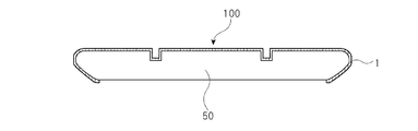
図3は、加飾成形体100の構成を説明する断面図である。図3は、表面に凹部を有する成形体50を加飾成形用積層体1で加飾した様子を示している。図3に示されているように、真空条件下又は減圧条件下での成形においては、成形体50に真空孔を設けなくても、逆テーパ部や末端巻き込み部を被覆成形することができる。また、製品の材質を問わずに、加飾することができる。これにより、複雑な三次元的凹凸を有する成形体表面についても加飾することができ、意匠性の高い加飾成形体100を得ることができる。
FIG. 3 is a cross-sectional view illustrating the configuration of the decorative molded
成形体50としては、ED鋼板、Mg合金、ステンレス(SUS)、アルミニウム合金などの金属材料や樹脂成形体を挙げることができるが、樹脂成形体であることが好ましい。例えば、ABS樹脂(アクリロニトリル、ブタジエン、及び、スチレンの共重合体)、AS樹脂(アクリロニトリル、スチレンの共重合体)、AAS樹脂(アクリロニトリル、アクリル、及び、スチレンの共重合体)、アクリル樹脂、ポリエチレンテレフタレート、ポリブチレンテレフタレート、ナイロン、ポリアセタール、ポリフェニレンオキシド、フェノール樹脂、ユリア樹脂、メラミン樹脂、液晶ポリマー、ポリテトラフロロエチレン、ポリフッ化ビニリデン、ポリサルフォン、ポリエーテルサルフォン、ポリアセタール、ポリエーテルエーテルケトン、ポリフェニレンサルファイド、ポリエーテイミド、ポリアミドイミド、ポリカーボネート、ポリエチレン、ポリプロピレン、ポリスチレン、ウレタン樹脂、塩化ビニリデン樹脂、塩化ビニル樹脂等を好ましく用いることができる。これらの樹脂をブレンドしてあっても構わない。例えば、ポリカーボネート含有樹脂等を好ましく例示することができる。ポリカーボネート含有樹脂としては、ポリカーボネートとポリブチレンテレフタレートがブレンドされた樹脂(PC・PBT)、ポリカーボネートとABS樹脂がブレンドされた樹脂(PC・ABS)、ポリカーボネートとPETがブレンドされた樹脂(PC・PET)等を特に好ましく用いることができる。また、ポリオレフィン樹脂としてはポリプロピレン(PP)を特に好ましく用いることができる。
Examples of the molded
本発明により得られる加飾成形体は、例えば、自動車部材(例えば、ボディー、バンパー、スポイラー、ミラー、ホイール、内装材等の部品であって、各種材質のもの)、二輪車用部材、鉄道車両用部材として用いることができる。また、加飾成形体は、家電製品等の電子機器や、家具、建築材料等の建材として用いることもできる。さらに、加飾成形体は、道路用資材(例えば、交通標識、防音壁等)、トンネル用資材(例えば、側壁板等)、楽器、容器、事務用品、スポーツ用品、玩具等にも用いることができる。 The decorative molded body obtained by the present invention is, for example, an automobile member (for example, parts such as a body, a bumper, a spoiler, a mirror, a wheel, an interior material, and various materials), a member for a two-wheeled vehicle, and a railway vehicle It can be used as a member. In addition, the decorative molded body can also be used as a building material such as electronic equipment such as home appliances, furniture, and building materials. Furthermore, the decorative molded body can also be used for road materials (for example, traffic signs, soundproof walls, etc.), tunnel materials (for example, side walls), musical instruments, containers, office supplies, sports equipment, toys, etc. it can.
以下に実施例と比較例を挙げて本発明の特徴をさらに具体的に説明する。以下の実施例に示す材料、使用量、割合、処理内容、処理手順等は、本発明の趣旨を逸脱しない限り適宜変更することができる。したがって、本発明の範囲は以下に示す具体例により限定的に解釈されるべきものではない。 The features of the present invention will be described more specifically with reference to examples and comparative examples. The materials, amounts used, ratios, processing details, processing procedures, and the like shown in the following examples can be changed as appropriate without departing from the spirit of the present invention. Therefore, the scope of the present invention should not be construed as being limited by the specific examples shown below.
<実施例1>
(積層体1)
剥離剤層面に凹部の平均深さ3μm、凹部の平均幅15μm、凹部の平均断面積225μm2の凹部を多数有するセパレーターの剥離剤層側とアクリルフィルム(三菱レイヨン社製、アクリプレンHBA001P、鉛筆硬度は2H、厚さ125μm)との間に、電子放射線硬化性樹脂1(UV1)を厚さが8μmとなるよう塗布(ウエットラミネート)した。なお、この厚さは、頂部から対向辺までの総厚である。その後、セパレーター側から高圧水銀ランプにて波長365nmの電子放射線を、照度が100mW/cm2、積算光量が500mJ/cm2となるように照射することによって電子放射線硬化性樹脂1を硬化させた。このようにして光硬化樹脂層を得た。その後、セパレーターを剥離し、基材層と光硬化樹脂層がこの順に積層された表面保護層からなる積層体1を得た。積層体1のヘイズと積層体最表面の十点平均粗さRzは表1の通りであった。
<Example 1>
(Laminate 1)
Average depth 3μm of recesses in the release agent layer surface, the average width 15μm recess, the average cross-sectional area 225 .mu.m 2 release agent layer side of the separator having a large number of concave portions and acrylic film of the recess (Mitsubishi Rayon Co., Ltd., Akuripuren HBA001P, pencil hardness 2H and a thickness of 125 μm), the electron radiation curable resin 1 (UV1) was applied (wet laminate) to a thickness of 8 μm. This thickness is the total thickness from the top to the opposite side. Thereafter, the electron radiation curable resin 1 was cured by irradiating the separator with a high-pressure mercury lamp with electron radiation having a wavelength of 365 nm so that the illuminance was 100 mW / cm 2 and the integrated light amount was 500 mJ / cm 2 . In this way, a photocurable resin layer was obtained. Then, the separator was peeled off to obtain a laminate 1 composed of a surface protective layer in which a base material layer and a photocurable resin layer were laminated in this order. Table 1 shows the haze of the laminate 1 and the ten-point average roughness Rz of the outermost surface of the laminate.
なお、電子放射線硬化性樹脂組成物1(UV1)としては、Z−975L(アイカ工業社製)を用いた。 In addition, as the electron radiation curable resin composition 1 (UV1), Z-975L (made by Aika Kogyo Co., Ltd.) was used.
<比較例1>
(積層体2)
基材としてアクリルフィルム(三菱レイヨン社製、アクリプレンHBA001P、鉛筆硬度は2H、厚さ125μm)を用いた。この基材の片面側に、電子放射線硬化性樹脂2(UV2)を、硬化後の厚みが5μmとなるように、バーコーターを用いて塗工した。次に、基材と電子放射線硬化性樹脂組成物2を100℃の熱風オーブン中に入れ、塗工した電子放射線硬化性樹脂組成物2を1分間乾燥させた。その後、高圧水銀ランプにて波長365nmの電子放射線を、照度が100mW/cm2、積算光量が500mJ/cm2となるように照射し、電子放射線硬化性樹脂2を硬化させることにより光硬化樹脂層を形成した。このようにして、基材層と光硬化樹脂層がこの順に積層された積層体2を得た。積層体2のヘイズと積層体最表面の十点平均粗さRzは表1の通りであった。
<Comparative Example 1>
(Laminate 2)
An acrylic film (manufactured by Mitsubishi Rayon Co., Ltd., Acryprene HBA001P, pencil hardness 2H, thickness 125 μm) was used as the substrate. On one side of this substrate, the electron radiation curable resin 2 (UV2) was applied using a bar coater so that the thickness after curing was 5 μm. Next, the substrate and the electron radiation
なお、電子放射線硬化性樹脂組成物2(UV2)としては、アクリルアクリレート(重量平均分子量:78000)30質量部と、トルエン30質量部と、酢酸エチル8.5質量部と、光開始剤である1−ヒドロキシシクロヘキシルフェニルケトン(チバ・スペシャリティケミカルズ株式会社製、イルガキュア184)1質量部と、一次平均粒子径が500nmの無機粒子30質量部の混合物を用いた。 The electron radiation curable resin composition 2 (UV2) is 30 parts by mass of acrylic acrylate (weight average molecular weight: 78000), 30 parts by mass of toluene, 8.5 parts by mass of ethyl acetate, and a photoinitiator. A mixture of 1 part by mass of 1-hydroxycyclohexyl phenyl ketone (manufactured by Ciba Specialty Chemicals Co., Ltd., Irgacure 184) and 30 parts by mass of inorganic particles having a primary average particle diameter of 500 nm was used.
<比較例2>
(積層体3)
基材としてアクリルフィルム(三菱レイヨン社製、アクリプレンHBA001P、鉛筆硬度は2H、厚さ125μm)を用いた。この基材の片面側に、電子放射線硬化性樹脂3(UV3)を、硬化後の厚みが5μmとなるように、バーコーターを用いて塗工した。次に、基材と電子放射線硬化性樹脂組成物3を100℃の熱風オーブン中に入れ、塗工した電子放射線硬化性樹脂組成物3を1分間乾燥させた。その後、高圧水銀ランプにて波長365nmの電子放射線を、照度が100mW/cm2、積算光量が500mJ/cm2となるように照射し、電子放射線硬化性樹脂3を硬化させることにより光硬化樹脂層を形成した。このようにして、基材層と光硬化樹脂層がこの順に積層された積層体3を得た。積層体3のヘイズと積層体最表面の十点平均粗さRzは表1の通りであった。
<Comparative example 2>
(Laminate 3)
An acrylic film (manufactured by Mitsubishi Rayon Co., Ltd., Acryprene HBA001P, pencil hardness 2H, thickness 125 μm) was used as the substrate. On one side of this substrate, the electron radiation curable resin 3 (UV3) was applied using a bar coater so that the thickness after curing was 5 μm. Next, the base material and the electron radiation curable resin composition 3 were placed in a hot air oven at 100 ° C., and the applied electron radiation curable resin composition 3 was dried for 1 minute. Thereafter, the photo-curing resin layer is formed by irradiating electron radiation having a wavelength of 365 nm with a high-pressure mercury lamp so that the illuminance is 100 mW / cm 2 and the integrated light quantity is 500 mJ / cm 2 and curing the electron radiation curable resin 3. Formed. Thus, the laminated body 3 by which the base material layer and the photocurable resin layer were laminated | stacked in this order was obtained. Table 1 shows the haze of the laminate 3 and the ten-point average roughness Rz of the outermost surface of the laminate.
なお、電子放射線硬化性樹脂組成物3(UV3)としては、アクリルアクリレート(重量平均分子量:78000)30質量部と、トルエン30質量部と、酢酸エチル8.5質量部と、光開始剤である1−ヒドロキシシクロヘキシルフェニルケトン(チバ・スペシャリティケミカルズ株式会社製、イルガキュア184)1質量部と、一次平均粒子径が40nmの無機微粒子30質量部の混合物を用いた。 The electron radiation curable resin composition 3 (UV3) is 30 parts by mass of acrylic acrylate (weight average molecular weight: 78000), 30 parts by mass of toluene, 8.5 parts by mass of ethyl acetate, and a photoinitiator. A mixture of 1 part by mass of 1-hydroxycyclohexyl phenyl ketone (manufactured by Ciba Specialty Chemicals Co., Ltd., Irgacure 184) and 30 parts by mass of inorganic fine particles having a primary average particle diameter of 40 nm was used.
<比較例3>
(積層体4)
基材としてアクリルフィルム(三菱レイヨン社製、アクリプレンHBA001P、鉛筆硬度は2H、厚さ125μm)を用いた。この基材の片面側に、粒子を実質的に含まない電子放射線硬化性樹脂4(UV4)を、硬化後の厚みが5μmとなるように、バーコーターを用いて塗工した。次に、基材と電子放射線硬化性樹脂組成物4を100℃の熱風オーブン中に入れ、塗工した電子放射線硬化性樹脂組成物4を1分間乾燥させた。その後、高圧水銀ランプにて波長365nmの電子放射線を、照度が100mW/cm2、積算光量が500mJ/cm2となるように照射し、電子放射線硬化性樹脂5を硬化させることにより光硬化樹脂層を形成した。このようにして、基材層と光硬化樹脂層がこの順に積層された積層体4を得た。積層体4のヘイズを測定した。
<Comparative Example 3>
(Laminate 4)
An acrylic film (manufactured by Mitsubishi Rayon Co., Ltd., Acryprene HBA001P, pencil hardness 2H, thickness 125 μm) was used as the substrate. On one side of the substrate, an electron radiation curable resin 4 (UV4) substantially free of particles was applied using a bar coater so that the thickness after curing was 5 μm. Next, the substrate and the electron radiation curable resin composition 4 were placed in a 100 ° C. hot air oven, and the applied electron radiation curable resin composition 4 was dried for 1 minute. Thereafter, the photo-curing resin layer is formed by irradiating the electron radiation having a wavelength of 365 nm with a high-pressure mercury lamp so that the illuminance is 100 mW / cm 2 and the integrated light quantity is 500 mJ / cm 2 to cure the electron radiation
なお、電子放射線硬化性樹脂組成物4(UV4)としては、アクリルアクリレート(重量平均分子量:78000)30質量部と、トルエン60質量部と、酢酸エチル8.5質量部と、光開始剤である1−ヒドロキシシクロヘキシルフェニルケトン(チバ・スペシャリティケミカルズ株式会社製、イルガキュア184)1質量部の混合物を用いた。 The electron radiation curable resin composition 4 (UV4) is 30 parts by mass of acrylic acrylate (weight average molecular weight: 78000), 60 parts by mass of toluene, 8.5 parts by mass of ethyl acetate, and a photoinitiator. A mixture of 1 part by mass of 1-hydroxycyclohexyl phenyl ketone (Ciba Specialty Chemicals, Irgacure 184) was used.
<比較例4>
(積層体5)
剥離剤層面に凹部の平均深さ0.5μm、平均幅0.5μmの凹凸があるセパレーターの剥離剤層側とアクリルフィルム(三菱レイヨン社製、アクリプレンHBA001P、鉛筆硬度は2H、厚さ125μm)との間に、電子放射線硬化性樹脂1(UV1)を厚さが8μmとなるよう塗布(ウエットラミネート)した。なお、電子放射線硬化性樹脂1の厚さは、凹部と凸部を含めた総厚である。その後、セパレーター側から高圧水銀ランプにて波長365nmの電子放射線を、照度が100mW/cm2、積算光量が500mJ/cm2となるように照射し、電子放射線硬化性樹脂1を硬化させることにより光硬化樹脂層を形成した。その後、セパレーターを剥離し、基材層と光硬化樹脂層がこの順に積層された表面保護層からなる積層体5を得た。積層体5のヘイズと積層体最表面の十点平均粗さRzは表1の通りであった。
<Comparative Example 4>
(Laminate 5)
The release agent layer side of the separator having an unevenness with an average depth of 0.5 μm and an average width of 0.5 μm on the surface of the release agent layer and an acrylic film (manufactured by Mitsubishi Rayon Co., Ltd., Acryprene HBA001P, pencil hardness 2H, thickness 125 μm) In between, the electron radiation curable resin 1 (UV1) was applied (wet laminate) so as to have a thickness of 8 μm. The thickness of the electron radiation curable resin 1 is the total thickness including the concave portions and the convex portions. After that, the electron radiation having a wavelength of 365 nm is irradiated from the separator side with a high-pressure mercury lamp so that the illuminance is 100 mW / cm 2 and the integrated light amount is 500 mJ / cm 2, and the electron radiation curable resin 1 is cured. A cured resin layer was formed. Then, the separator was peeled off to obtain a
なお、電子放射線硬化性樹脂組成物1(UV1)としては、Z−975L(アイカ工業社製)を用いた。 In addition, as the electron radiation curable resin composition 1 (UV1), Z-975L (made by Aika Kogyo Co., Ltd.) was used.
(評価)
(表面保護層のヘイズ)
実施例1の積層体1、比較例1の積層体2、比較例2の積層体3、比較例3の積層体4、比較例4の積層体5のヘイズをJIS K 7136に準じ、日本電色工業株式会社製ヘイズメーター「NDH−5000」を用いて測定した。
(Evaluation)
(Haze of surface protective layer)
The haze of the laminate 1 of Example 1, the
(表面凸凹)
実施例1の積層体1、比較例1の積層体2、比較例2の積層体3、比較例3の積層体4、比較例4の積層体5の表面凸凹を目視観察し、面感を確認した。
○:表面の反射が抑えられている。
△:表面の反射がやや抑えられている。
×:表面の反射が抑制できていない。
(Surface unevenness)
The surface irregularities of the laminated body 1 of Example 1, the
○: Reflection on the surface is suppressed.
Δ: Reflection on the surface is somewhat suppressed.
X: Reflection on the surface is not suppressed.
(十点平均粗さRz)
実施例1の積層体1、比較例1の積層体2、比較例2の積層体3、比較例3の積層体4、比較例4の積層体5の最表面を、マイクロレーザー顕微鏡(株式会社KEYENCE製測定部VK−X105、コントローラー部VK−X100)を用いて、倍率200倍で表面観察を行い、画像の取り込みを行った。得られた画像について、測定エリアを100μm×100μmとしてマイクロレーザー顕微鏡に付属の解析ソフトウェアを用いて、十点平均粗さRzを測定した。
(10-point average roughness Rz)
The outermost surface of the laminated body 1 of Example 1, the
(成形性評価試験)
実施例1の積層体1、比較例1の積層体2、比較例2の積層体3、比較例3の積層体4、比較例4の積層体5について、TOM成形機(布施真空株式会社製、NGF成形機)を用いて積層体長手方向および幅方向の延伸倍率が50%以上になる条件で加飾成形(成形温度120℃)し、加飾成形体を得た。被着体として、防雨入線カバー(品番:WP9171[パナソニック株式会社製])を使用した。上記加飾成形体について、以下の評価基準に従い成形性を評価した。
○:積層体の最大延伸部(積層体長手方向および幅方向の延伸倍率50%以上)にて、積層体の破断が見られなかった。
△:積層体の最大延伸部(積層体長手方向および幅方向の延伸倍率50%以上)にて、積層体の破断が一部見られたが、実用上の問題は無い。
×:積層体の最大延伸部(積層体長手方向および幅方向の延伸倍率50%以上)にて、積層体の破断が見られた。
(Formability evaluation test)
About the laminated body 1 of Example 1, the
A: No breakage of the laminate was observed at the maximum stretched portion of the laminate (stretching ratio in the longitudinal direction of the laminate and the width direction of 50% or more).
Δ: Some breakage of the laminate was observed at the maximum stretched portion of the laminate (stretch ratio in the longitudinal direction and the width direction of 50% or more), but there was no practical problem.
X: Breakage of the laminate was observed at the maximum stretched portion of the laminate (stretching ratio in the longitudinal direction of the laminate and the width direction of 50% or more).
(破断伸度)
実施例1の積層体1、比較例1の積層体2、比較例2の積層体3、比較例3の積層体4、比較例4の積層体5をTOM成形機(布施真空株式会社製、NGF成形機)を用いて、120℃下において加飾成形用積層体の長手方向又は幅方向の延伸倍率が10から100%まで、10%刻みの測定可能な治具を使用し、成形を行い、成形体を得た。そして、表面保護層の一部に破壊が生じる前の延伸倍率を加飾成形用積層体の破断伸度とした。100%の延伸倍率においても破壊が生じなかったものは「>100」と評価した。例えば、10%ずつ延伸倍率を変えながら試験を行い、90%延伸した際に成形体表面に初めて破壊が見られた場合、破断伸度を80%とした。
(Elongation at break)
The laminated body 1 of Example 1, the

(ヘイズ低下率)
実施例1の積層体1、比較例1の積層体2、比較例2の積層体3、比較例3の積層体4、比較例4の積層体5をそれぞれ、一方向に50%延伸した後、ヘイズをJIS K 7136に準じ、日本電色工業株式会社製ヘイズメーター「NDH−5000」を用いて測定した。
その後延伸前のヘイズPと、延伸後のヘイズQの値から、下記式によりヘイズ低下率を算出した。
ヘイズ低下率(%)=(P−Q/P)×100
(Haze reduction rate)
After stretching the laminated body 1 of Example 1, the
Thereafter, the haze reduction rate was calculated from the haze P before stretching and the haze Q value after stretching by the following formula.
Haze reduction rate (%) = (PQ / P) × 100
(全光線透過率)
実施例1の積層体1、比較例1の積層体2、比較例2の積層体3、比較例3の積層体4、比較例4の積層体5の全光線透過率をJIS K 7136に準じ、日本電色工業株式会社製ヘイズメーター「NDH−5000」を用いて測定した。さらに、実施例1の積層体1、比較例1の積層体2、比較例2の積層体3、比較例3の積層体4、比較例4の積層体5をそれぞれ、一方向に50%延伸した後の全光線透過率も同様の方法で測定した。
(Total light transmittance)
The total light transmittance of the laminated body 1 of Example 1, the
実施例で得られた積層体は、延伸前のヘイズが高く加飾性に優れていた。また、実施例で得られた積層体は、破断伸度が高く、かつ延伸前後のヘイズの変化率が低く抑えられていることがわかる。 The laminates obtained in the examples had high haze before stretching and excellent decorating properties. Moreover, it turns out that the laminated body obtained by the Example has high elongation at break, and the haze change rate before and behind extending | stretching is suppressed low.
1 加飾成形用積層体
2 表面保護層
3 基材層
5 光硬化樹脂層
10 凸部
50 成形体
100 加飾成形体
DESCRIPTION OF SYMBOLS 1 Layered body for
Claims (10)
前記表面保護層のヘイズは10%以上であり、
前記加飾成形用積層体の第1の方向の120℃における破断伸度は50%より大きく、かつ前記第1の方向と直交する第2の方向の120℃における破断伸度は50%より大きく、
前記加飾成形用積層体を延伸する前の表面保護層のヘイズをPとし、前記加飾成形用積層体を第1の方向または第2の方向に50%延伸した後の表面保護層のヘイズをQとした場合、(P−Q/P)×100で表されるヘイズ低下率が40%以下であることを特徴とする加飾成形用積層体。 A decorative molded laminate including a surface protective layer having a photocurable resin on the outermost surface,
The haze of the surface protective layer is 10% or more,
The breaking elongation at 120 ° C. in the first direction of the decorative molding laminate is greater than 50%, and the breaking elongation at 120 ° C. in the second direction orthogonal to the first direction is greater than 50%. ,
The haze of the surface protective layer after stretching the decorative laminate by 50% in the first direction or the second direction is defined as P, which is the haze of the surface protective layer before stretching the decorative laminate. Is a laminate for decorative molding, wherein the haze reduction rate represented by (PQ / P) × 100 is 40% or less.
気圧差により、前記加飾成形用積層体を成形体に圧着する工程とを含む加飾成形体の製造方法であって、
前記加飾成形用積層体は、最表面に光硬化樹脂を有する表面保護層を含み、
前記表面保護層のヘイズは10%以上であり、
前記加飾成形用積層体の第1の方向の120℃における破断伸度は50%より大きく、かつ前記第1の方向と直交する第2の方向の120℃における破断伸度は50%より大きく、
前記加飾成形用積層体を延伸する前の表面保護層のヘイズをPとし、前記加飾成形用積層体を第1の方向または第2の方向に50%延伸した後の表面保護層のヘイズをQとした場合、(P−Q/P)×100で表されるヘイズ低下率が40%以下である加飾成形体の製造方法。 A step of laminating a decorative molded laminate on a molded body under vacuum or reduced pressure conditions;
A method for producing a decorative molded body including a step of pressure-bonding the laminate for decorative molding to a molded body by pressure difference,
The decorative molding laminate includes a surface protective layer having a photocurable resin on the outermost surface,
The haze of the surface protective layer is 10% or more,
The breaking elongation at 120 ° C. in the first direction of the decorative molding laminate is greater than 50%, and the breaking elongation at 120 ° C. in the second direction orthogonal to the first direction is greater than 50%. ,
The haze of the surface protective layer after stretching the decorative laminate by 50% in the first direction or the second direction is defined as P, which is the haze of the surface protective layer before stretching the decorative laminate. Is the manufacturing method of the decorative molded object whose haze reduction rate represented by (PQ / P) x100 is 40% or less.
Priority Applications (1)
| Application Number | Priority Date | Filing Date | Title |
|---|---|---|---|
| JP2016029650A JP6544262B2 (en) | 2016-02-19 | 2016-02-19 | LAMINATE FOR DECORATIVE FORMING, DECORATED MOLDED BODY, AND METHOD FOR MANUFACTURING DECORATED MOLDED BODY |
Applications Claiming Priority (1)
| Application Number | Priority Date | Filing Date | Title |
|---|---|---|---|
| JP2016029650A JP6544262B2 (en) | 2016-02-19 | 2016-02-19 | LAMINATE FOR DECORATIVE FORMING, DECORATED MOLDED BODY, AND METHOD FOR MANUFACTURING DECORATED MOLDED BODY |
Publications (2)
| Publication Number | Publication Date |
|---|---|
| JP2017144683A true JP2017144683A (en) | 2017-08-24 |
| JP6544262B2 JP6544262B2 (en) | 2019-07-17 |
Family
ID=59681860
Family Applications (1)
| Application Number | Title | Priority Date | Filing Date |
|---|---|---|---|
| JP2016029650A Active JP6544262B2 (en) | 2016-02-19 | 2016-02-19 | LAMINATE FOR DECORATIVE FORMING, DECORATED MOLDED BODY, AND METHOD FOR MANUFACTURING DECORATED MOLDED BODY |
Country Status (1)
| Country | Link |
|---|---|
| JP (1) | JP6544262B2 (en) |
Citations (6)
| Publication number | Priority date | Publication date | Assignee | Title |
|---|---|---|---|---|
| JPH04125198A (en) * | 1990-09-17 | 1992-04-24 | Dainippon Printing Co Ltd | Suede tone transfer foil |
| JPH05138736A (en) * | 1991-04-15 | 1993-06-08 | Dainippon Printing Co Ltd | Molded product having uneven surface |
| JP2010030248A (en) * | 2008-07-31 | 2010-02-12 | Sumitomo Chemical Co Ltd | Matted resin film |
| JP2010234346A (en) * | 2009-03-31 | 2010-10-21 | Dainippon Printing Co Ltd | Method of manufacturing decoration sheet |
| JP2014104705A (en) * | 2012-11-29 | 2014-06-09 | Toppan Printing Co Ltd | Transfer film |
| JP2015145103A (en) * | 2014-02-03 | 2015-08-13 | 日本ペイント・オートモーティブコーティングス株式会社 | Laminate film for decorating molded article, paint composition and decorative molded article |
-
2016
- 2016-02-19 JP JP2016029650A patent/JP6544262B2/en active Active
Patent Citations (6)
| Publication number | Priority date | Publication date | Assignee | Title |
|---|---|---|---|---|
| JPH04125198A (en) * | 1990-09-17 | 1992-04-24 | Dainippon Printing Co Ltd | Suede tone transfer foil |
| JPH05138736A (en) * | 1991-04-15 | 1993-06-08 | Dainippon Printing Co Ltd | Molded product having uneven surface |
| JP2010030248A (en) * | 2008-07-31 | 2010-02-12 | Sumitomo Chemical Co Ltd | Matted resin film |
| JP2010234346A (en) * | 2009-03-31 | 2010-10-21 | Dainippon Printing Co Ltd | Method of manufacturing decoration sheet |
| JP2014104705A (en) * | 2012-11-29 | 2014-06-09 | Toppan Printing Co Ltd | Transfer film |
| JP2015145103A (en) * | 2014-02-03 | 2015-08-13 | 日本ペイント・オートモーティブコーティングス株式会社 | Laminate film for decorating molded article, paint composition and decorative molded article |
Also Published As
| Publication number | Publication date |
|---|---|
| JP6544262B2 (en) | 2019-07-17 |
Similar Documents
| Publication | Publication Date | Title |
|---|---|---|
| JP4985288B2 (en) | Decorative sheet for 3D processing | |
| KR20100124291A (en) | Decorative sheet for three-dimensional work | |
| JP2007191693A (en) | Method for producing multi-purpose plastic product having surface preferentially having wear resistance | |
| JP6601494B2 (en) | Adhesive film, laminate, and decorative molded body | |
| JP2011504828A (en) | Hard coat film for graphic substrate | |
| JP2019507029A (en) | Acrylic film with structured layer | |
| US7361402B2 (en) | Cross-linked primer composition and use thereof in thermoformable films | |
| JP6627576B2 (en) | Decorative laminate, decorative molded article, and method of manufacturing decorative molded article | |
| JP6717650B2 (en) | Follow-up adhesive film for application to uneven surface of decorative member and method for producing the same | |
| KR101103409B1 (en) | High-glossy curved surface decoration panel and manufacturing method of the same | |
| JP6693519B2 (en) | Decorative laminate | |
| KR20080070424A (en) | Lamination sheet for decoration and transparent panel having three-dimentional property using the same | |
| JP6619259B2 (en) | Adhesive film and method for producing the same | |
| JP2021138002A (en) | Decorative sheet and method for producing decorative article using the same | |
| JP6544262B2 (en) | LAMINATE FOR DECORATIVE FORMING, DECORATED MOLDED BODY, AND METHOD FOR MANUFACTURING DECORATED MOLDED BODY | |
| JP2006021377A (en) | Decorative metallic tone film and its manufacturing method | |
| JP2018051864A (en) | Decorative sheet and molded article using the same | |
| JP6662303B2 (en) | Laminates and decorative moldings | |
| WO2023042290A1 (en) | Decorative sheet and method for manufacturing decorative article using same | |
| JP7467962B2 (en) | Decorative film and decorative molded body | |
| JP2012116128A (en) | Decorative sheet for secondary processing and method of manufacturing decorative material using the same | |
| JP7143054B2 (en) | Decorative sheet and molded product using the same | |
| JP2021172753A (en) | Production method of adhesive, heat shrinkage resistant adhesive film, and ionizing radiation curable adhesive composition | |
| JP2017154382A (en) | Laminated body for decoration, decorative molded body, and method for producing decorative molded body | |
| JP2021160164A (en) | Decorative film and decorated molded object |
Legal Events
| Date | Code | Title | Description |
|---|---|---|---|
| A621 | Written request for application examination |
Free format text: JAPANESE INTERMEDIATE CODE: A621 Effective date: 20180604 |
|
| A977 | Report on retrieval |
Free format text: JAPANESE INTERMEDIATE CODE: A971007 Effective date: 20190215 |
|
| A131 | Notification of reasons for refusal |
Free format text: JAPANESE INTERMEDIATE CODE: A131 Effective date: 20190326 |
|
| A521 | Request for written amendment filed |
Free format text: JAPANESE INTERMEDIATE CODE: A523 Effective date: 20190509 |
|
| TRDD | Decision of grant or rejection written | ||
| A01 | Written decision to grant a patent or to grant a registration (utility model) |
Free format text: JAPANESE INTERMEDIATE CODE: A01 Effective date: 20190521 |
|
| A61 | First payment of annual fees (during grant procedure) |
Free format text: JAPANESE INTERMEDIATE CODE: A61 Effective date: 20190603 |
|
| R150 | Certificate of patent or registration of utility model |
Ref document number: 6544262 Country of ref document: JP Free format text: JAPANESE INTERMEDIATE CODE: R150 |
|
| R250 | Receipt of annual fees |
Free format text: JAPANESE INTERMEDIATE CODE: R250 |
|
| R250 | Receipt of annual fees |
Free format text: JAPANESE INTERMEDIATE CODE: R250 |