JP2017144615A - Laminate, production method of laminate, and processing method of substrate - Google Patents
Laminate, production method of laminate, and processing method of substrate Download PDFInfo
- Publication number
- JP2017144615A JP2017144615A JP2016027413A JP2016027413A JP2017144615A JP 2017144615 A JP2017144615 A JP 2017144615A JP 2016027413 A JP2016027413 A JP 2016027413A JP 2016027413 A JP2016027413 A JP 2016027413A JP 2017144615 A JP2017144615 A JP 2017144615A
- Authority
- JP
- Japan
- Prior art keywords
- layer
- light
- metal
- shielding layer
- substrate
- Prior art date
- Legal status (The legal status is an assumption and is not a legal conclusion. Google has not performed a legal analysis and makes no representation as to the accuracy of the status listed.)
- Granted
Links
Images


Abstract
Description
本発明は、積層体、積層体の製造方法、及び基板の処理方法に関する。 The present invention relates to a laminate, a method for manufacturing a laminate, and a substrate processing method.
近年、ICカード、携帯電話等の電子機器の薄型化、小型化、軽量化等が要求されている。これらの要求を満たすためには、組み込まれる半導体チップについても薄型の半導体チップを使用しなければならない。このため、半導体チップの基となるウエハ基板の厚さ(膜厚)は、現状では125μm〜150μmであるが、次世代のチップ用には25μm〜50μmにしなければならないといわれている。従って、上記の膜厚のウエハ基板を得るためには、ウエハ基板の薄板化工程が必要不可欠である。 In recent years, electronic devices such as IC cards and mobile phones have been required to be thinner, smaller and lighter. In order to satisfy these requirements, a thin semiconductor chip must be used as a semiconductor chip to be incorporated. For this reason, the thickness (film thickness) of the wafer substrate that is the basis of the semiconductor chip is currently 125 μm to 150 μm, but it is said that it must be 25 μm to 50 μm for next-generation chips. Therefore, in order to obtain a wafer substrate having the above film thickness, a wafer substrate thinning process is indispensable.
ウエハ基板は、薄板化により強度が低下するので、薄板化したウエハ基板の破損を防ぐために、製造プロセス中は、ウエハ基板に支持体を貼り合わされた状態で自動搬送しながら、ウエハ基板上に回路等の構造物を実装する。そして、製造プロセス後に、ウエハ基板を支持体から分離する。そこで、ウエハ基板から支持体を剥離する様々な方法が用いられている。 Since the strength of the wafer substrate decreases due to the thinning of the wafer substrate, a circuit is formed on the wafer substrate while automatically supporting the substrate while the support is bonded to the wafer substrate to prevent damage to the thinned wafer substrate. Etc. are mounted. Then, after the manufacturing process, the wafer substrate is separated from the support. Therefore, various methods for peeling the support from the wafer substrate are used.
積層体から基板を剥離する方法としては、分離層にレーザ光を照射する方法が用いられている。例えば、特許文献1では、支持体を介して照射される光を吸収することによって変質する分離層を備えた積層体が記載されている。
As a method of peeling the substrate from the laminate, a method of irradiating the separation layer with laser light is used. For example,
また、特許文献2には、透過する光の透過量を低減する接着剤組成物により形成されている接着層を備えた積層体が記載されており、特許文献3には、光吸収層と遮光層とを備えた分離層が形成された積層体が記載されている。
基板から支持体を剥離するために分離層に光を照射したときにおいて、分離層を透過した光が基板まで到達することを好適に防止することができる新規な積層体は、基板に形成された素子等の構造物が光により損傷することを防止することができるため有用である。 A novel laminate that can suitably prevent light transmitted through the separation layer from reaching the substrate when the separation layer is irradiated with light to peel the support from the substrate is formed on the substrate. This is useful because structures such as elements can be prevented from being damaged by light.
これについて、本願発明者らは、独自の知見に基づき鋭意検討した結果、積層体において、遮光層を金属、金属酸化物、及び、金属窒化物からなる群から選択される少なくとも1つにより形成し、分離層に上記遮光層に含まれる金属、金属の酸化物、及び、金属の窒化物を含まない構成とすることにより、分離層を透過した光を遮光層によって好適に遮光することができることを見出し、本願発明を完成させた。 As a result of intensive studies based on original knowledge, the inventors of the present application have formed a light shielding layer of at least one selected from the group consisting of metals, metal oxides, and metal nitrides in the laminate. The structure in which the separation layer does not include the metal, metal oxide, and metal nitride contained in the light shielding layer allows light transmitted through the separation layer to be suitably shielded by the light shielding layer. The headline and the present invention were completed.
すなわち、本発明は、上記の問題点に鑑みてなされたものであり、その目的は、基板から支持体を剥離するために分離層に光を照射したときにおいて、分離層を透過した光が基板まで到達することを好適に防止することができる新規な積層体、及び、その関連技術を提供することにある。 That is, the present invention has been made in view of the above-described problems, and the purpose of the present invention is that when the separation layer is irradiated with light to peel the support from the substrate, the light transmitted through the separation layer is the substrate. It is an object of the present invention to provide a novel laminate and a related technique that can suitably prevent reaching the above point.
上記の課題を解決するために、本発明に係る積層体は、基板と、光を透過する支持体とを、接着層と、遮光層と、光を吸収することにより変質する分離層とを介して積層してなる積層体であって、上記遮光層は、上記基板と上記分離層との間に形成されており、上記遮光層は、金属、当該金属の酸化物、及び、当該金属の窒化物からなる群から選択される少なくとも1つを含んでなり、上記分離層は、上記遮光層に含まれる金属、金属の酸化物、及び、金属の窒化物を含んでいないことを特徴としている。 In order to solve the above-described problems, a laminate according to the present invention includes a substrate, a support that transmits light, an adhesive layer, a light-shielding layer, and a separation layer that is altered by absorbing light. The light shielding layer is formed between the substrate and the separation layer, and the light shielding layer comprises a metal, an oxide of the metal, and a nitridation of the metal. It comprises at least one selected from the group consisting of materials, and the separation layer is characterized by not containing the metal, metal oxide, and metal nitride contained in the light shielding layer.
本発明によれば、基板から支持体を剥離するために分離層に光を照射したときにおいて、分離層を透過した光が基板まで到達することを好適に防止することができる新規な積層体及びその関連技術を提供することができるという効果を奏する。 According to the present invention, when the separation layer is irradiated with light in order to peel the support from the substrate, a novel laminate that can suitably prevent the light transmitted through the separation layer from reaching the substrate and The related technique can be provided.
<積層体10>
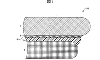
図1を用いて、本発明の一実施形態に係る積層体10について、より詳細に説明する。図1は、本発明の一実施形態に係る積層体10の概略を説明する図である。
<Laminated
The laminated
図1に示すように、本実施形態に係る積層体10は、基板1と、サポートプレート(支持体)2とを、接着層3と、分離層4と、遮光層5とを介して積層してなる積層体である。つまり、積層体10は、基板1と、光を透過するサポートプレート2とを、接着層3と、遮光層5と、光を吸収することにより変質する分離層4とを介して積層してなる積層体であって、遮光層5は、基板1と分離層4との間に形成されている。
As shown in FIG. 1, a
上記の構成によれば、光を透過するサポートプレート2から分離層4に向かって照射される光が、基板1に到達することを遮光層5によって好適に防止することができる。
According to said structure, it can prevent suitably with the
また、遮光層5は、金属、当該金属の酸化物、及び、当該金属の窒化物からなる群から選択される少なくとも1つを含んでなり、分離層4は、遮光層5に含まれる金属、金属の酸化物、及び、金属の窒化物を含んでいない。
The
上記の構成によれば、サポートプレート2を介して、分離層4に光を照射したときにおいて、分離層4を透過した光を遮光層5によってサポートプレート2側に反射するか、又は、遮光層5が当該光を吸収することで変質することを防止しつつ、当該光が基板側に透過することを防止することができる。従って、分離層4に照射された光によって遮光層5が変質することがない、または変質が少ないので、当該遮光層5によって光が基板1に到達することを好適に防止することができる。
According to the above configuration, when the separation layer 4 is irradiated with light through the
[基板]
基板1は、サポートプレート2に支持された状態で、薄化、実装等のプロセスに供され得る。また、基板1には、例えば、集積回路や金属バンプ等の構造物が実装されている。
[substrate]
The
基板1は、典型的には、シリコンウエハ基板を用いることができるが、限定されず、セラミックス基板、薄いフィルム基板、フレキシブル基板等の任意の材質からなる基板を使用してもよい。
The
[サポートプレート]
サポートプレート(支持体)2は、基板1を支持する支持体であり、接着層3を介して、基板1に貼り付けられる。そのため、サポートプレート2としては、基板1の薄化、搬送、実装等のプロセス時に、基板1の破損又は変形を防ぐために必要な強度を有していればよい。また、サポートプレート2は、分離層4を変質させるための光を透過するものであればよい。これらの観点から、サポートプレート2には、ガラス、シリコン、又は、アクリル系樹脂からなる支持体等を用いることができる。なお、基板1を支持するサポートプレートの種類は、分離層4に照射される光の波長に応じて、適宜選択すればよい。
[Support plate]
The support plate (support) 2 is a support that supports the
[接着層]
接着層3は、基板1とサポートプレート2とを貼り付けるための層であり、基板1とサポートプレート2とを貼り付けるために用いられる接着剤によって形成される。
[Adhesive layer]
The
接着層3を形成するための接着剤は、熱可塑性樹脂、希釈剤、及び、添加剤等のその他の成分を含有している。ここで、接着剤が含有している熱可塑性樹脂、つまり、接着層3が含有する熱可塑性樹脂としては、接着性を備えたものであればよく、例えば、炭化水素樹脂、アクリル−スチレン系樹脂、マレイミド系樹脂、エラストマー樹脂、ポリサルホン系樹脂等、又はこれらを組み合わせたもの等をより好ましく用いることができる。以下、本実施の形態における接着層3が含有する熱可塑性樹脂について説明する。
The adhesive for forming the
(炭化水素樹脂)
炭化水素樹脂は、炭化水素骨格を有し、単量体組成物を重合してなる樹脂である。炭化水素樹脂として、シクロオレフィン系ポリマー(以下、「樹脂(A)」ということがある)、並びに、テルペン樹脂、ロジン系樹脂及び石油樹脂からなる群より選ばれる少なくとも1種の樹脂(以下、「樹脂(B)」ということがある)等が挙げられるが、これに限定されない。
(Hydrocarbon resin)
The hydrocarbon resin is a resin that has a hydrocarbon skeleton and is obtained by polymerizing a monomer composition. As the hydrocarbon resin, cycloolefin polymer (hereinafter sometimes referred to as “resin (A)”), and at least one resin selected from the group consisting of terpene resin, rosin resin and petroleum resin (hereinafter referred to as “resin (A)”). Resin (B) ”), and the like, but is not limited thereto.
樹脂(A)は、シクロオレフィン系モノマーを含む単量体成分を重合してなる樹脂であってもよい。具体的には、シクロオレフィン系モノマーを含む単量体成分の開環(共)重合体、シクロオレフィン系モノマーを含む単量体成分を付加(共)重合させた樹脂等が挙げられる。 The resin (A) may be a resin obtained by polymerizing a monomer component containing a cycloolefin monomer. Specific examples include a ring-opening (co) polymer of a monomer component containing a cycloolefin monomer, and a resin obtained by addition (co) polymerization of a monomer component containing a cycloolefin monomer.
樹脂(A)を構成する単量体成分に含まれる上記シクロオレフィン系モノマーとしては、例えば、ノルボルネン、ノルボルナジエン等の二環体、ジシクロペンタジエン、ヒドロキシジシクロペンタジエン等の三環体、テトラシクロドデセン等の四環体、シクロペンタジエン三量体等の五環体、テトラシクロペンタジエン等の七環体、又はこれら多環体のアルキル(メチル、エチル、プロピル、ブチル等)置換体、アルケニル(ビニル等)置換体、アルキリデン(エチリデン等)置換体、アリール(フェニル、トリル、ナフチル等)置換体等が挙げられる。これらの中でも特に、ノルボルネン、テトラシクロドデセン、又はこれらのアルキル置換体からなる群より選ばれるノルボルネン系モノマーが好ましい。 Examples of the cycloolefin monomer contained in the monomer component constituting the resin (A) include bicyclic compounds such as norbornene and norbornadiene, tricyclic compounds such as dicyclopentadiene and hydroxydicyclopentadiene, and tetracyclodone. Tetracycles such as decene, pentacycles such as cyclopentadiene trimer, heptacycles such as tetracyclopentadiene, or alkyl (methyl, ethyl, propyl, butyl, etc.) substitutes of these polycycles, alkenyl (vinyl) Etc.) Substitutes, alkylidene (ethylidene, etc.) substitutes, aryl (phenyl, tolyl, naphthyl, etc.) substitutes and the like. Among these, norbornene-based monomers selected from the group consisting of norbornene, tetracyclododecene, and alkyl-substituted products thereof are particularly preferable.
樹脂(A)を構成する単量体成分は、上述したシクロオレフィン系モノマーと共重合可能な他のモノマーを含有していてもよく、例えば、アルケンモノマーを含有することが好ましい。アルケンモノマーとしては、例えば、エチレン、プロピレン、1−ブテン、イソブテン、1−ヘキセン、α−オレフィン等が挙げられる。アルケンモノマーは、直鎖状であってもよいし、分岐鎖状であってもよい。 The monomer component constituting the resin (A) may contain another monomer copolymerizable with the above-described cycloolefin-based monomer, and preferably contains, for example, an alkene monomer. Examples of the alkene monomer include ethylene, propylene, 1-butene, isobutene, 1-hexene, α-olefin and the like. The alkene monomer may be linear or branched.
また、樹脂(A)を構成する単量体成分として、シクロオレフィンモノマーを含有することが、高耐熱性(低い熱分解、熱重量減少性)の観点から好ましい。樹脂(A)を構成する単量体成分全体に対するシクロオレフィンモノマーの割合は、5モル%以上であることが好ましく、10モル%以上であることがより好ましく、20モル%以上であることがさらに好ましい。また、樹脂(A)を構成する単量体成分全体に対するシクロオレフィンモノマーの割合は、特に限定されないが、溶解性及び溶液での経時安定性の観点からは80モル%以下であることが好ましく、70モル%以下であることがより好ましい。 Moreover, it is preferable from a viewpoint of high heat resistance (low thermal decomposition and thermal weight reduction property) to contain a cycloolefin monomer as a monomer component which comprises resin (A). The ratio of the cycloolefin monomer to the whole monomer component constituting the resin (A) is preferably 5 mol% or more, more preferably 10 mol% or more, and further preferably 20 mol% or more. preferable. Further, the ratio of the cycloolefin monomer to the whole monomer component constituting the resin (A) is not particularly limited, but is preferably 80 mol% or less from the viewpoint of solubility and stability over time in a solution, More preferably, it is 70 mol% or less.
また、樹脂(A)を構成する単量体成分として、直鎖状又は分岐鎖状のアルケンモノマーを含有してもよい。樹脂(A)を構成する単量体成分全体に対するアルケンモノマーの割合は、溶解性及び柔軟性の観点からは10〜90モル%であることが好ましく、20〜85モル%であることがより好ましく、30〜80モル%であることがさらに好ましい。 Moreover, you may contain a linear or branched alkene monomer as a monomer component which comprises resin (A). The ratio of the alkene monomer to the whole monomer component constituting the resin (A) is preferably 10 to 90 mol%, more preferably 20 to 85 mol% from the viewpoint of solubility and flexibility. 30 to 80 mol% is more preferable.
なお、樹脂(A)は、例えば、シクロオレフィン系モノマーとアルケンモノマーとからなる単量体成分を重合させてなる樹脂のように、極性基を有していない樹脂であることが、高温下でのガスの発生を抑制する上で好ましい。 The resin (A) is a resin having no polar group, such as a resin obtained by polymerizing a monomer component composed of a cycloolefin monomer and an alkene monomer, at high temperatures. It is preferable for suppressing generation of gas.
単量体成分を重合するときの重合方法や重合条件等については、特に制限はなく、常法に従い適宜設定すればよい。 The polymerization method and polymerization conditions for polymerizing the monomer components are not particularly limited, and may be set as appropriate according to conventional methods.
例えば、下記化学式(1)で表される繰り返し単位及び下記化学式(2)で表される繰り返し単位の共重合体であるシクロオレフィンコポリマーを接着成分の樹脂(A)として用いることができる。 For example, a cycloolefin copolymer which is a copolymer of a repeating unit represented by the following chemical formula (1) and a repeating unit represented by the following chemical formula (2) can be used as the adhesive component resin (A).

(化学式(2)中、nは0又は1〜3の整数である。)
このようなシクロオレフィンコポリマーとしては、APL 8008T、APL 8009T、及びAPL 6013T(全て三井化学株式会社製)等を使用することができる。
(In chemical formula (2), n is 0 or an integer of 1 to 3)
As such cycloolefin copolymer, APL 8008T, APL 8009T, APL 6013T (all manufactured by Mitsui Chemicals, Inc.) and the like can be used.
また、樹脂(A)として用いることのできる市販品としては、例えば、ポリプラスチックス株式会社製の「TOPAS」、三井化学株式会社製の「APEL」、日本ゼオン株式会社製の「ZEONOR」及び「ZEONEX」、JSR株式会社製の「ARTON」等が挙げられる。 Examples of commercially available products that can be used as the resin (A) include “TOPAS” manufactured by Polyplastics Co., Ltd., “APEL” manufactured by Mitsui Chemicals, Inc., “ZEONOR” manufactured by Nippon Zeon Co., Ltd., and “ “ZEONEX”, “ARTON” manufactured by JSR Corporation, and the like.
樹脂(A)のガラス転移温度(Tg)は、60℃以上であることが好ましく、70℃以上であることが特に好ましい。樹脂(A)のガラス転移温度が60℃以上であると、積層体が高温環境に曝されたときに接着層3の軟化をさらに抑制することができる。
The glass transition temperature (Tg) of the resin (A) is preferably 60 ° C. or higher, and particularly preferably 70 ° C. or higher. When the glass transition temperature of the resin (A) is 60 ° C. or higher, softening of the
樹脂(B)は、テルペン系樹脂、ロジン系樹脂及び石油樹脂からなる群より選ばれる少なくとも1種の樹脂である。具体的には、テルペン系樹脂としては、例えば、テルペン樹脂、テルペンフェノール樹脂、変性テルペン樹脂、水添テルペン樹脂、水添テルペンフェノール樹脂等が挙げられる。ロジン系樹脂としては、例えば、ロジン、ロジンエステル、水添ロジン、水添ロジンエステル、重合ロジン、重合ロジンエステル、変性ロジン等が挙げられる。石油樹脂としては、例えば、脂肪族又は芳香族石油樹脂、水添石油樹脂、変性石油樹脂、脂環族石油樹脂、クマロン・インデン石油樹脂等が挙げられる。これらの中でも、水添テルペン樹脂、水添石油樹脂がより好ましい。 The resin (B) is at least one resin selected from the group consisting of terpene resins, rosin resins and petroleum resins. Specifically, examples of the terpene resin include terpene resins, terpene phenol resins, modified terpene resins, hydrogenated terpene resins, hydrogenated terpene phenol resins, and the like. Examples of the rosin resin include rosin, rosin ester, hydrogenated rosin, hydrogenated rosin ester, polymerized rosin, polymerized rosin ester, and modified rosin. Examples of petroleum resins include aliphatic or aromatic petroleum resins, hydrogenated petroleum resins, modified petroleum resins, alicyclic petroleum resins, coumarone-indene petroleum resins, and the like. Among these, hydrogenated terpene resins and hydrogenated petroleum resins are more preferable.
樹脂(B)の軟化点は特に限定されないが、80〜160℃であることが好ましい。樹脂(B)の軟化点が80〜160℃であると、積層体が高温環境に曝されたときに軟化することを抑制することができ、接着不良を生じない。 Although the softening point of resin (B) is not specifically limited, It is preferable that it is 80-160 degreeC. When the softening point of the resin (B) is 80 to 160 ° C., the laminate can be prevented from being softened when exposed to a high-temperature environment, and adhesion failure does not occur.
樹脂(B)の重量平均分子量は特に限定されないが、300〜3,000であることが好ましい。樹脂(B)の重量平均分子量が300以上であると、耐熱性が十分なものとなり、高温環境下において脱ガス量が少なくなる。一方、樹脂(B)の重量平均分子量が3,000以下であると、炭化水素系溶剤への接着層の溶解速度が良好なものとなる。このため、支持体を分離した後の基板上の接着層の残渣を迅速に溶解し、除去することができる。なお、本実施形態における樹脂(B)の重量平均分子量は、ゲル・パーミエーション・クロマトグラフィー(GPC)で測定されるポリスチレン換算の分子量を意味するものである。 Although the weight average molecular weight of resin (B) is not specifically limited, It is preferable that it is 300-3,000. When the weight average molecular weight of the resin (B) is 300 or more, the heat resistance is sufficient, and the degassing amount is reduced in a high temperature environment. On the other hand, when the weight average molecular weight of the resin (B) is 3,000 or less, the dissolution rate of the adhesive layer in the hydrocarbon solvent is good. For this reason, the residue of the adhesive layer on the substrate after separating the support can be quickly dissolved and removed. In addition, the weight average molecular weight of resin (B) in this embodiment means the molecular weight of polystyrene conversion measured by gel permeation chromatography (GPC).
なお、樹脂として、樹脂(A)と樹脂(B)とを混合したものを用いてもよい。混合することにより、耐熱性が良好なものとなる。例えば、樹脂(A)と樹脂(B)との混合割合としては、(A):(B)=80:20〜55:45(質量比)であることが、高温環境時の熱耐性、及び柔軟性に優れるので好ましい。 In addition, you may use what mixed resin (A) and resin (B) as resin. By mixing, heat resistance becomes good. For example, the mixing ratio of the resin (A) and the resin (B) is (A) :( B) = 80: 20 to 55:45 (mass ratio), and heat resistance in a high temperature environment, and It is preferable because of its excellent flexibility.
(アクリル−スチレン系樹脂)
アクリル−スチレン系樹脂としては、例えば、スチレン又はスチレンの誘導体と、(メタ)アクリル酸エステル等とを単量体として用いて重合した樹脂が挙げられる。
(Acrylic-styrene resin)
Examples of the acrylic-styrene resin include a resin obtained by polymerization using styrene or a styrene derivative and (meth) acrylic acid ester as monomers.
(メタ)アクリル酸エステルとしては、例えば、鎖式構造からなる(メタ)アクリル酸アルキルエステル、脂肪族環を有する(メタ)アクリル酸エステル、芳香族環を有する(メタ)アクリル酸エステルが挙げられる。鎖式構造からなる(メタ)アクリル酸アルキルエステルとしては、炭素数15〜20のアルキル基を有するアクリル系長鎖アルキルエステル、炭素数1〜14のアルキル基を有するアクリル系アルキルエステル等が挙げられる。アクリル系長鎖アルキルエステルとしては、アルキル基がn−ペンタデシル基、n−ヘキサデシル基、n−ヘプタデシル基、n−オクタデシル基、n−ノナデシル基、n−エイコシル基等であるアクリル酸又はメタクリル酸のアルキルエステルが挙げられる。なお、当該アルキル基は、分岐鎖状であってもよい。 Examples of the (meth) acrylic acid ester include a (meth) acrylic acid alkyl ester having a chain structure, a (meth) acrylic acid ester having an aliphatic ring, and a (meth) acrylic acid ester having an aromatic ring. . Examples of the (meth) acrylic acid alkyl ester having a chain structure include an acrylic long-chain alkyl ester having an alkyl group having 15 to 20 carbon atoms and an acrylic alkyl ester having an alkyl group having 1 to 14 carbon atoms. . As acrylic long-chain alkyl esters, acrylic or methacrylic acid whose alkyl group is n-pentadecyl group, n-hexadecyl group, n-heptadecyl group, n-octadecyl group, n-nonadecyl group, n-eicosyl group, etc. Examples include alkyl esters. The alkyl group may be branched.
炭素数1〜14のアルキル基を有するアクリル系アルキルエステルとしては、既存のアクリル系接着剤に用いられている公知のアクリル系アルキルエステルが挙げられる。例えば、アルキル基が、メチル基、エチル基、プロピル基、ブチル基、2−エチルヘキシル基、イソオクチル基、イソノニル基、イソデシル基、ドデシル基、ラウリル基、トリデシル基等からなるアクリル酸又はメタクリル酸のアルキルエステルが挙げられる。 Examples of the acrylic alkyl ester having an alkyl group having 1 to 14 carbon atoms include known acrylic alkyl esters used in existing acrylic adhesives. For example, an alkyl group of acrylic acid or methacrylic acid in which the alkyl group is a methyl group, ethyl group, propyl group, butyl group, 2-ethylhexyl group, isooctyl group, isononyl group, isodecyl group, dodecyl group, lauryl group, tridecyl group, etc. Examples include esters.
脂肪族環を有する(メタ)アクリル酸エステルとしては、シクロヘキシル(メタ)アクリレート、シクロペンチル(メタ)アクリレート、1−アダマンチル(メタ)アクリレート、ノルボルニル(メタ)アクリレート、イソボルニル(メタ)アクリレート、トリシクロデカニル(メタ)アクリレート、テトラシクロドデカニル(メタ)アクリレート、ジシクロペンタニル(メタ)アクリレート等が挙げられるが、イソボルニルメタアクリレート、ジシクロペンタニル(メタ)アクリレートがより好ましい。 Examples of (meth) acrylic acid ester having an aliphatic ring include cyclohexyl (meth) acrylate, cyclopentyl (meth) acrylate, 1-adamantyl (meth) acrylate, norbornyl (meth) acrylate, isobornyl (meth) acrylate, and tricyclodecanyl. (Meth) acrylate, tetracyclododecanyl (meth) acrylate, dicyclopentanyl (meth) acrylate and the like can be mentioned, and isobornyl methacrylate and dicyclopentanyl (meth) acrylate are more preferable.
芳香族環を有する(メタ)アクリル酸エステルとしては、特に限定されるものではないが、芳香族環としては、例えばフェニル基、ベンジル基、トリル基、キシリル基、ビフェニル基、ナフチル基、アントラセニル基、フェノキシメチル基、フェノキシエチル基等が挙げられる。また、芳香族環は、炭素数1〜5の直鎖状又は分岐鎖状のアルキル基を有していてもよい。具体的には、フェノキシエチルアクリレートが好ましい。 The (meth) acrylic acid ester having an aromatic ring is not particularly limited. Examples of the aromatic ring include a phenyl group, a benzyl group, a tolyl group, a xylyl group, a biphenyl group, a naphthyl group, and an anthracenyl group. A phenoxymethyl group, a phenoxyethyl group, and the like. The aromatic ring may have a linear or branched alkyl group having 1 to 5 carbon atoms. Specifically, phenoxyethyl acrylate is preferable.
(マレイミド系樹脂)
マレイミド系樹脂としては、例えば、単量体として、N−メチルマレイミド、N−エチルマレイミド、N−n−プロピルマレイミド、N−イソプロピルマレイミド、N−n−ブチルマレイミド、N−イソブチルマレイミド、N−sec−ブチルマレイミド、N−tert−ブチルマレイミド、N−n−ペンチルマレイミド、N−n−ヘキシルマレイミド、N−n−へプチルマレイミド、N−n−オクチルマレイミド、N−ラウリルマレイミド、N−ステアリルマレイミド等のアルキル基を有するマレイミド、N−シクロプロピルマレイミド、N−シクロブチルマレイミド、N−シクロペンチルマレイミド、N−シクロヘキシルマレイミド、N−シクロヘプチルマレイミド、N−シクロオクチルマレイミド等の脂肪族炭化水素基を有するマレイミド、N−フェニルマレイミド、N−m−メチルフェニルマレイミド、N−o−メチルフェニルマレイミド、N−p−メチルフェニルマレイミド等のアリール基を有する芳香族マレイミド等を重合して得られた樹脂が挙げられる。
(Maleimide resin)
Examples of maleimide resins include N-methylmaleimide, N-ethylmaleimide, Nn-propylmaleimide, N-isopropylmaleimide, Nn-butylmaleimide, N-isobutylmaleimide, N-sec as monomers. -Butylmaleimide, N-tert-butylmaleimide, Nn-pentylmaleimide, Nn-hexylmaleimide, Nn-heptylmaleimide, Nn-octylmaleimide, N-laurylmaleimide, N-stearylmaleimide, etc. Male having an aliphatic hydrocarbon group such as maleimide having an alkyl group, N-cyclopropylmaleimide, N-cyclobutylmaleimide, N-cyclopentylmaleimide, N-cyclohexylmaleimide, N-cycloheptylmaleimide, N-cyclooctylmaleimide A resin obtained by polymerizing an aromatic maleimide having an aryl group such as N, N-phenylmaleimide, Nm-methylphenylmaleimide, N-o-methylphenylmaleimide, and Np-methylphenylmaleimide. It is done.
(エラストマー)
エラストマーは、主鎖の構成単位としてスチレン単位を含んでいることが好ましく、当該「スチレン単位」は置換基を有していてもよい。当該置換基としては、例えば、炭素数1〜5のアルキル基、炭素数1〜5のアルコキシ基、炭素数1〜5のアルコキシアルキル基、アセトキシ基、カルボキシル基等が挙げられる。また、当該スチレン単位の含有量が14重量%以上、50重量%以下の範囲内であることがより好ましい。さらに、エラストマーは、重量平均分子量が10,000以上、200,000以下の範囲内であることが好ましい。
(Elastomer)
The elastomer preferably contains a styrene unit as a constituent unit of the main chain, and the “styrene unit” may have a substituent. Examples of the substituent include an alkyl group having 1 to 5 carbon atoms, an alkoxy group having 1 to 5 carbon atoms, an alkoxyalkyl group having 1 to 5 carbon atoms, an acetoxy group, and a carboxyl group. Further, the content of the styrene unit is more preferably in the range of 14 wt% or more and 50 wt% or less. Furthermore, the elastomer preferably has a weight average molecular weight in the range of 10,000 to 200,000.
スチレン単位の含有量が14重量%以上、50重量%以下の範囲内であり、エラストマーの重量平均分子量が10,000以上、200,000以下の範囲内であれば、後述する炭化水素系の溶剤(溶媒)に容易に溶解するので、より容易かつ迅速に接着層を除去することができる。また、スチレン単位の含有量及び重量平均分子量が上記の範囲内であることにより、ウエハ基板がレジストリソグラフィー工程に供されるときに曝されるレジスト溶剤(例えばPGMEA、PGME等)、酸(フッ化水素酸等)、アルカリ(TMAH等)に対して優れた耐性を発揮する。 If the content of the styrene unit is in the range of 14% by weight or more and 50% by weight or less, and the weight average molecular weight of the elastomer is in the range of 10,000 or more and 200,000 or less, the hydrocarbon solvent described later Since it dissolves easily in (solvent), the adhesive layer can be removed more easily and quickly. In addition, since the content of the styrene unit and the weight average molecular weight are within the above ranges, the resist solvent (eg, PGMEA, PGME, etc.), acid (fluorinated) exposed when the wafer substrate is subjected to the resist lithography process. Hydroxic acid etc.) and alkali (TMAH etc.) exhibit excellent resistance.
なお、エラストマーには、上述した(メタ)アクリル酸エステルをさらに混合してもよい。 In addition, you may further mix the (meth) acrylic acid ester mentioned above with the elastomer.
スチレン単位の含有量は、より好ましくは17重量%以上であり、また、より好ましくは40重量%以下である。 The content of styrene units is more preferably 17% by weight or more, and more preferably 40% by weight or less.
重量平均分子量のより好ましい範囲は20,000以上であり、また、より好ましい範囲は150,000以下である。 A more preferable range of the weight average molecular weight is 20,000 or more, and a more preferable range is 150,000 or less.
エラストマーとしては、スチレン単位の含有量が14重量%以上、50重量%以下の範囲内であり、エラストマーの重量平均分子量が10,000以上、200,000以下の範囲内であれば、種々のエラストマーを用いることができる。例えば、ポリスチレン−ポリ(エチレン/プロピレン)ブロックコポリマー(SEP)、スチレン−イソプレン−スチレンブロックコポリマー(SIS)、スチレン−ブタジエン−スチレンブロックコポリマー(SBS)、スチレン−ブタジエン−ブチレン−スチレンブロックコポリマー(SBBS)、及び、これらの水添物、スチレン−エチレン−ブチレン−スチレンブロックコポリマー(SEBS)、スチレン−エチレン−プロピレン−スチレンブロックコポリマー(スチレン−イソプレン−スチレンブロックコポリマー)(SEPS)、スチレン−エチレン−エチレン−プロピレン−スチレンブロックコポリマー(SEEPS)、スチレンブロックが反応架橋型のスチレン−エチレン−エチレン−プロピレン−スチレンブロックコポリマー(SeptonV9461(株式会社クラレ製)、SeptonV9475(株式会社クラレ製))、スチレンブロックが反応架橋型のスチレン−エチレン−ブチレン−スチレンブロックコポリマー(反応性のポリスチレン系ハードブロックを有する、SeptonV9827(株式会社クラレ製))、ポリスチレン−ポリ(エチレン−エチレン/プロピレン)ブロック−ポリスチレンブロックコポリマー(SEEPS−OH:末端水酸基変性)等が挙げられ、エラストマーのスチレン単位の含有量及び重量平均分子量が上述の範囲内であるものを用いることができる。 As the elastomer, various elastomers can be used as long as the content of styrene units is in the range of 14% by weight to 50% by weight and the weight average molecular weight of the elastomer is in the range of 10,000 to 200,000. Can be used. For example, polystyrene-poly (ethylene / propylene) block copolymer (SEP), styrene-isoprene-styrene block copolymer (SIS), styrene-butadiene-styrene block copolymer (SBS), styrene-butadiene-butylene-styrene block copolymer (SBBS). And hydrogenated products thereof, styrene-ethylene-butylene-styrene block copolymer (SEBS), styrene-ethylene-propylene-styrene block copolymer (styrene-isoprene-styrene block copolymer) (SEPS), styrene-ethylene-ethylene- Propylene-styrene block copolymer (SEEPS), styrene-ethylene-ethylene-propylene-styrene block copolypropylene in which styrene block is reactively crosslinked -(Septon V9461 (manufactured by Kuraray Co., Ltd.), Septon V9475 (manufactured by Kuraray Co., Ltd.)), Septon V9827 (Co., Ltd., which has a reactive polystyrene-based hard block) Kuraray)), polystyrene-poly (ethylene-ethylene / propylene) block-polystyrene block copolymer (SEEPS-OH: terminal hydroxyl group modification), etc., and the content of styrene units and weight average molecular weight of the elastomer are within the above-mentioned ranges. Can be used.
また、エラストマーの中でも水添物がより好ましい。水添物であれば熱に対する安定性が向上し、分解や重合等の変質が起こり難い。また、炭化水素系溶剤への溶解性及びレジスト溶剤への耐性の観点からもより好ましい。 Of the elastomers, hydrogenated products are more preferable. If it is a hydrogenated product, the stability to heat is improved, and degradation such as decomposition and polymerization hardly occurs. Moreover, it is more preferable from the viewpoint of solubility in hydrocarbon solvents and resistance to resist solvents.
また、エラストマーの中でも両端がスチレンのブロック重合体であるものがより好ましい。熱安定性の高いスチレンを両末端にブロックすることでより高い耐熱性を示すからである。 Further, among elastomers, those having both ends of a styrene block polymer are more preferable. This is because styrene having high thermal stability is blocked at both ends, thereby exhibiting higher heat resistance.
より具体的には、エラストマーは、スチレン及び共役ジエンのブロックコポリマーの水添物であることがより好ましい。熱に対する安定性が向上し、分解や重合等の変質が起こり難い。また、熱安定性の高いスチレンを両末端にブロックすることでより高い耐熱性を示す。さらに、炭化水素系溶剤への溶解性及びレジスト溶剤への耐性の観点からもより好ましい。 More specifically, the elastomer is more preferably a hydrogenated product of a block copolymer of styrene and conjugated diene. Stability against heat is improved, and degradation such as decomposition and polymerization hardly occurs. Moreover, higher heat resistance is exhibited by blocking styrene having high thermal stability at both ends. Furthermore, it is more preferable from the viewpoint of solubility in hydrocarbon solvents and resistance to resist solvents.
接着層3を構成する接着剤に含まれるエラストマーとして用いられ得る市販品としては、例えば、株式会社クラレ製「セプトン(商品名)」、株式会社クラレ製「ハイブラー(商品名)」、旭化成株式会社製「タフテック(商品名)」、JSR株式会社製「ダイナロン(商品名)」等が挙げられる。
Examples of commercially available products that can be used as an elastomer included in the adhesive constituting the
接着層3を構成する接着剤に含まれるエラストマーの含有量としては、例えば、接着剤組成物全量を100重量部として、50重量部以上、99重量部以下の範囲内が好ましく、60重量部以上、99重量部以下の範囲内がより好ましく、70重量部以上、95重量部以下の範囲内が最も好ましい。これら範囲内にすることにより、耐熱性を維持しつつ、基板と支持体とを好適に貼り合わせることができる。
The content of the elastomer contained in the adhesive constituting the
また、エラストマーは、複数の種類を混合してもよい。つまり、接着層3を構成する接着剤は複数の種類のエラストマーを含んでいてもよい。そして、複数の種類のエラストマーのうち少なくとも一つが、主鎖の構成単位としてスチレン単位を含んでいればよい。また、複数の種類のエラストマーのうち少なくとも一つが、スチレン単位の含有量が14重量%以上、50重量%以下の範囲内である、又は、重量平均分子量が10,000以上、200,000以下の範囲内であれば、本発明の範疇である。また、接着層3を構成する接着剤において、複数の種類のエラストマーを含む場合、混合した結果、スチレン単位の含有量が上記の範囲内となるように調整してもよい。例えば、スチレン単位の含有量が30重量%である株式会社クラレ製のセプトン(商品名)のSepton4033と、スチレン単位の含有量が13重量%であるセプトン(商品名)のSepton2063とを重量比1対1で混合すると、接着剤に含まれるエラストマー全体に対するスチレン含有量は21〜22重量%となり、従って14重量%以上となる。また、例えば、スチレン単位が10重量%のものと60重量%のものとを重量比1対1で混合すると35重量%となり、上記の範囲内となる。本発明はこのような形態でもよい。また、接着層3を構成する接着剤に含まれる複数の種類のエラストマーは、全て上記の範囲内でスチレン単位を含み、かつ、上記の範囲内の重量平均分子量であることが最も好ましい。
A plurality of types of elastomers may be mixed. That is, the adhesive constituting the
なお、光硬化性樹脂(例えば、UV硬化性樹脂)以外の樹脂を用いて接着層3を形成することが好ましい。光硬化性樹脂以外の樹脂を用いることで、接着層3の剥離又は除去の後に、基板1の微小な凹凸の周辺に残渣が生じることを防ぐことができる。特に、接着層3を構成する接着剤としては、あらゆる溶剤に溶解するものではなく、特定の溶剤に溶解するものが好ましい。これは、基板1に物理的な力を加えることなく、接着層3を溶剤に溶解させることによって除去可能なためである。接着層3の除去に際して、強度が低下した基板1からでさえ、基板1を破損させたり、変形させたりせずに、容易に接着層3を除去することができる。
Note that the
(ポリサルホン系樹脂)
接着層3を形成するための接着剤は、ポリサルホン系樹脂を含んでいてもよい。接着層3をポリサルホン系樹脂によって形成することにより、高温において積層体を処理しても、その後の工程において接着層を溶解し、基板から支持体を剥離することが可能な積層体を製造することができる。接着層3がポリサルホン樹脂を含んでいれば、例えば、アニーリング等により積層体を300℃以上という高温で処理する高温プロセスにおいても、積層体を好適に用いることができる。
(Polysulfone resin)
The adhesive for forming the
ポリサルホン系樹脂は、下記一般式(3)で表される構成単位、及び、下記一般式(4)で表される構成単位のうちの少なくとも1種の構成単位からなる構造を有している。 The polysulfone-based resin has a structure composed of at least one structural unit of a structural unit represented by the following general formula (3) and a structural unit represented by the following general formula (4).
(ここで、一般式(3)のR1、R2及びR3、並びに一般式(4)中のR1及びR2は、それぞれ独立してフェニレン基、ナフチレン基及びアントリレン基からなる群より選択され、X’は、炭素数が1以上、3以下のアルキレン基である。)
ポリサルホン系樹脂は、式(3)で表されるポリサルホン構成単位及び式(4)で表されるポリエーテルサルホン構成単位のうちの少なくとも1つを備えていることによって、基板1とサポートプレート2とを貼り付けた後、高い温度条件において基板1を処理しても、分解及び重合等により接着層3が不溶化することを防止することができる積層体を形成することができる。また、ポリサルホン系樹脂は、上記式(3)で表されるポリサルホン構成単位からなるポリサルホン樹脂であれば、より高い温度に加熱しても安定である。このため、洗浄後の基板1に接着層に起因する残渣が生じることを防止することができる。
(Wherein, R 1 and R 2 of R 1, R 2 and R 3, as well as the general formula (4) of the general formula (3) are each independently a phenylene group, from the group consisting of naphthylene group and an anthrylene group And X ′ is an alkylene group having 1 to 3 carbon atoms.)
The polysulfone-based resin includes at least one of the polysulfone constituent unit represented by the formula (3) and the polyethersulfone constituent unit represented by the formula (4), whereby the
ポリサルホン系樹脂の重量平均分子量(Mw)は、30,000以上、70,000以下の範囲内であることが好ましく、30,000以上、50,000以下の範囲内であることがより好ましい。ポリサルホン系樹脂の重量平均分子量(Mw)が、30,000以上の範囲内であれば、例えば、300℃以上の高い温度において用いることができる接着剤組成物を得ることができる。また、ポリサルホン系樹脂の重量平均分子量(Mw)が、70,000以下の範囲内であれば、溶剤によって好適に溶解することができる。つまり、溶剤によって好適に除去することができる接着剤組成物を得ることができる。 The weight average molecular weight (Mw) of the polysulfone-based resin is preferably in the range of 30,000 to 70,000, and more preferably in the range of 30,000 to 50,000. If the weight average molecular weight (Mw) of the polysulfone-based resin is within a range of 30,000 or more, an adhesive composition that can be used at a high temperature of 300 ° C. or more can be obtained. Moreover, if the weight average molecular weight (Mw) of polysulfone-type resin is in the range of 70,000 or less, it can melt | dissolve suitably with a solvent. That is, an adhesive composition that can be suitably removed with a solvent can be obtained.
(希釈溶剤)
希釈溶剤は、接着層3を形成するための接着剤において、熱可塑性樹脂を希釈するために用いられる。接着剤において、熱可塑性樹脂を希釈する希釈溶剤は、熱可塑性樹脂の種類によって適宜設計することができる。
(Diluted solvent)
The dilution solvent is used to dilute the thermoplastic resin in the adhesive for forming the
より具体的には、熱可塑性樹脂として、例えば、炭化水素樹脂、及びエラストマー等を用いる場合、希釈溶剤として、炭化水素、テルペン系溶剤を用いることが好ましい。また、熱可塑性樹脂として、例えば、アクリル−スチレン系樹脂、マレイミド系樹脂、及びポリサルホン系樹脂等を用いる場合、希釈溶剤として、ラクトン類、ケトン類、多価アルコール類、多価アルコール類の誘導体、環式エーテル類、エステル類、芳香族系有機溶剤、非プロトン性極性溶剤等を用いることが好ましい。 More specifically, when a hydrocarbon resin, an elastomer, or the like is used as the thermoplastic resin, it is preferable to use a hydrocarbon or a terpene solvent as the dilution solvent. In addition, when using, for example, an acrylic-styrene resin, a maleimide resin, a polysulfone resin, or the like as the thermoplastic resin, as a diluent solvent, lactones, ketones, polyhydric alcohols, polyhydric alcohol derivatives, It is preferable to use cyclic ethers, esters, aromatic organic solvents, aprotic polar solvents, and the like.
希釈溶剤として用いられる炭化水素には、ヘキサン、ヘプタン、オクタン、ノナン、メチルオクタン、デカン、ウンデカン、ドデカン、トリデカン等の直鎖状の炭化水素、炭素数4から15の分岐鎖状の炭化水素、例えば、シクロヘキサン、シクロヘプタン、シクロオクタン、ナフタレン、デカヒドロナフタレン、テトラヒドロナフタレン等の環状炭化水素等を挙げることができる。テルペン系溶剤には、p−メンタン、o−メンタン、m−メンタン、ジフェニルメンタン、1,4−テルピン、1,8−テルピン、ボルナン、ノルボルナン、ピナン、ツジャン、カラン、ロンギホレン、ゲラニオール、ネロール、リナロール、シトラール、シトロネロール、メントール、イソメントール、ネオメントール、α−テルピネオール、β−テルピネオール、γ−テルピネオール、テルピネン−1−オール、テルピネン−4−オール、ジヒドロターピニルアセテート、1,4−シネオール、1,8−シネオール、ボルネオール、カルボン、ヨノン、ツヨン、カンファー、d−リモネン、l−リモネン、ジペンテン等を挙げることができる。 Hydrocarbons used as a diluent solvent include straight-chain hydrocarbons such as hexane, heptane, octane, nonane, methyloctane, decane, undecane, dodecane, and tridecane, branched hydrocarbons having 4 to 15 carbon atoms, Examples thereof include cyclic hydrocarbons such as cyclohexane, cycloheptane, cyclooctane, naphthalene, decahydronaphthalene and tetrahydronaphthalene. Terpene solvents include p-menthane, o-menthane, m-menthane, diphenylmenthane, 1,4-terpine, 1,8-terpine, bornane, norbornane, pinane, tsujang, karan, longifolene, geraniol, nerol, linalool , Citral, citronellol, menthol, isomenthol, neomenthol, α-terpineol, β-terpineol, γ-terpineol, terpinen-1-ol, terpinen-4-ol, dihydroterpinyl acetate, 1,4-cineole, 1 , 8-cineole, borneol, carvone, yonon, thuyon, camphor, d-limonene, l-limonene, dipentene and the like.
また、希釈溶剤として用いられるラクトン類には、γ−ブチロラクトン等を挙げることができ、ケトン類には、アセトン、メチルエチルケトン、シクロヘキサノン(CH)、メチル−n−ペンチルケトン、メチルイソペンチルケトン、2−ヘプタノン等を挙げることができる。多価アルコール類には、エチレングリコール、ジエチレングリコール、プロピレングリコール、ジプロピレングリコール等を挙げることができる。また、多価アルコール類の誘導体には、上記多価アルコールのエステル類、上記多価アルコール類及び上記多価アルコールのエステル類のエーテル等を挙げることができる。ここで、上記多価アルコールのエステル類には、エチレングリコールモノアセテート、ジエチレングリコールモノアセテート、プロピレングリコールモノアセテート、又はジプロピレングリコールモノアセテート等を挙げることができる。また、上記多価アルコール類のエーテル、及び、上記多価アルコールのエステル類のエーテルには、これらの多価アルコール類又は多価アルコールのエステル類のモノメチルエーテル、モノエチルエーテル、モノプロピルエーテル、モノブチルエーテル等のモノアルキルエーテル又はモノフェニルエーテル等を挙げることができ、このような、多価アルコール類の誘導体では、プロピレングリコールモノメチルエーテルアセテート(PGMEA)、プロピレングリコールモノメチルエーテル(PGME)が好ましい。また、環式エーテル類には、ジオキサン等を挙げることができ、エステル類には、乳酸メチル、乳酸エチル(EL)、酢酸メチル、酢酸エチル、酢酸ブチル、メトキシブチルアセテート、ピルビン酸メチル、ピルビン酸エチル、メトキシプロピオン酸メチル、エトキシプロピオン酸エチル等を挙げることができる。芳香族系有機溶剤には、アニソール、エチルベンジルエーテル、クレジルメチルエーテル、ジフェニルエーテル、ジベンジルエーテル、フェネトール、ブチルフェニルエーテル等を挙げることができる。また、非プロトン性極性溶剤としては、N−メチル−2−ピロリドン(NMP)、ジメチルスルホキシド(DMSO)、ジメチルホルムアミド(DMF)、及びジメチルアセトアミド(DMA)等を挙げることができる。 Examples of lactones used as a diluent solvent include γ-butyrolactone, and examples of ketones include acetone, methyl ethyl ketone, cyclohexanone (CH), methyl-n-pentyl ketone, methyl isopentyl ketone, 2- Heptanone etc. can be mentioned. Examples of the polyhydric alcohols include ethylene glycol, diethylene glycol, propylene glycol, and dipropylene glycol. Examples of the derivatives of polyhydric alcohols include esters of the polyhydric alcohols, ethers of the polyhydric alcohols and polyhydric alcohol esters, and the like. Examples of the polyhydric alcohol esters include ethylene glycol monoacetate, diethylene glycol monoacetate, propylene glycol monoacetate, and dipropylene glycol monoacetate. The polyhydric alcohol ethers and the polyhydric alcohol esters ether include monomethyl ether, monoethyl ether, monopropyl ether, monopolyether of these polyhydric alcohols or polyhydric alcohol esters. Examples thereof include monoalkyl ethers such as butyl ether, monophenyl ethers, and the like. Among these polyhydric alcohol derivatives, propylene glycol monomethyl ether acetate (PGMEA) and propylene glycol monomethyl ether (PGME) are preferable. Examples of cyclic ethers include dioxane, and esters include methyl lactate, ethyl lactate (EL), methyl acetate, ethyl acetate, butyl acetate, methoxybutyl acetate, methyl pyruvate, and pyruvate. Examples thereof include ethyl, methyl methoxypropionate, and ethyl ethoxypropionate. Examples of the aromatic organic solvent include anisole, ethyl benzyl ether, cresyl methyl ether, diphenyl ether, dibenzyl ether, phenetole, and butyl phenyl ether. Examples of the aprotic polar solvent include N-methyl-2-pyrrolidone (NMP), dimethyl sulfoxide (DMSO), dimethylformamide (DMF), and dimethylacetamide (DMA).
(その他の成分)
接着層3を構成する接着剤は、本質的な特性を損なわない範囲において、混和性のある他の物質をさらに含んでいてもよい。例えば、接着剤の性能を改良するための付加的樹脂、可塑剤、接着補助剤、安定剤、着色剤、熱重合禁止剤及び界面活性剤等、慣用されている各種添加剤をさらに用いることができる。
(Other ingredients)
The adhesive constituting the
[分離層]
分離層4は、サポートプレート2を介して照射される光を吸収することによって変質する材料から形成されている層である。
[Separation layer]
The separation layer 4 is a layer formed from a material that is altered by absorbing light irradiated through the
分離層4の厚さは、例えば、0.05μm以上、50μm以下の範囲内であることがより好ましく、0.3μm以上、1μm以下の範囲内であることがさらに好ましい。分離層4の厚さが0.05μm以上、50μm以下の範囲に収まっていれば、短時間の光の照射及び低エネルギーの光の照射によって、分離層4に所望の変質を生じさせることができる。また、分離層4の厚さは、生産性の観点から1μm以下の範囲に収まっていることが特に好ましい。 For example, the thickness of the separation layer 4 is more preferably in the range of 0.05 μm or more and 50 μm or less, and further preferably in the range of 0.3 μm or more and 1 μm or less. If the thickness of the separation layer 4 is in the range of 0.05 μm or more and 50 μm or less, desired alteration can be caused in the separation layer 4 by short-time light irradiation and low-energy light irradiation. . The thickness of the separation layer 4 is particularly preferably within a range of 1 μm or less from the viewpoint of productivity.
なお、本明細書において、分離層が「変質する」とは、分離層がわずかな外力を受けて破壊され得る状態、又は分離層と接する層との接着力が低下した状態になる現象を意味する。光を吸収することによって生じる分離層の変質の結果として、分離層は、光の照射を受ける前の強度又は接着性を失う。つまり、光を吸収することによって、分離層は脆くなる。分離層の変質とは、分離層が、吸収した光のエネルギーによる分解、立体配置の変化又は官能基の解離等を生じることであり得る。分離層の変質は、光を吸収することの結果として生じる。 In this specification, the “deterioration” of the separation layer means a phenomenon in which the separation layer can be broken by receiving a slight external force, or a state in which the adhesive force with the layer in contact with the separation layer is reduced. To do. As a result of the alteration of the separation layer caused by absorbing light, the separation layer loses its strength or adhesion prior to light irradiation. In other words, the separation layer becomes brittle by absorbing light. The alteration of the separation layer may mean that the separation layer causes decomposition due to absorbed light energy, a change in configuration, dissociation of a functional group, or the like. The alteration of the separating layer occurs as a result of absorbing light.
よって、例えば、サポートプレートを持ち上げるだけで分離層が破壊されるように変質させて、サポートプレートと基板とを容易に分離することができる。より具体的には、例えば、支持体分離装置等により、積層体における基板及びサポートプレートの一方を載置台に固定し、吸着手段を備えた吸着パッド(吸着部)等によって他方を保持して持ち上げることで、サポートプレートと基板とを分離するか、又はサポートプレートの周縁部分端部の面取り部位を、クランプ(ツメ部)等を備えた分離プレートによって把持することにより力を加え、基板とサポートプレートとを分離するとよい。また、例えば、接着剤を剥離するための剥離液を供給する剥離手段を備えた支持体分離装置によって、積層体における基板からサポートプレートを剥離してもよい。当該剥離手段によって積層体における接着層の周端部の少なくとも一部に剥離液を供給し、積層体における接着層を膨潤させることにより、当該接着層が膨潤したところから分離層に力が集中するようにして、基板とサポートプレートとに力を加えることができる。このため、基板とサポートプレートとを好適に分離することができる。 Therefore, for example, it is possible to easily separate the support plate and the substrate by changing the quality so that the separation layer is broken only by lifting the support plate. More specifically, for example, one of the substrate and the support plate in the stacked body is fixed to the mounting table by a support separating device or the like, and the other is held and lifted by a suction pad (suction part) provided with suction means. Thus, the support plate and the substrate are separated, or a force is applied by gripping the chamfered portion of the end portion of the peripheral portion of the support plate with the separation plate provided with a clamp (claw portion) or the like. And should be separated. Further, for example, the support plate may be peeled from the substrate in the laminated body by a support separating apparatus provided with a peeling means for supplying a peeling liquid for peeling the adhesive. The peeling means supplies the peeling liquid to at least a part of the peripheral end portion of the adhesive layer in the laminate, and the adhesive layer in the laminate is swollen so that the force concentrates on the separation layer from where the adhesive layer swells. In this way, a force can be applied to the substrate and the support plate. For this reason, a board | substrate and a support plate can be isolate | separated suitably.
積層体に加える力は、積層体の大きさ等により適宜調整すればよく、限定されるものではないが、例えば、直径が300mm程度の積層体であれば、0.1〜5kgf程度の力を加えることによって、基板とサポートプレートとを好適に分離することができる。 The force applied to the laminated body may be appropriately adjusted depending on the size of the laminated body, and is not limited. For example, if the laminated body has a diameter of about 300 mm, a force of about 0.1 to 5 kgf is applied. By adding, a board | substrate and a support plate can be isolate | separated suitably.
なお、積層体10において、分離層4とサポートプレート2との間に他の層がさらに形成されていてもよい。この場合、他の層は光を透過する材料から構成されていればよい。これによって、分離層4への光の入射を妨げることなく、積層体10に好ましい性質等を付与する層を、適宜追加することができる。分離層4を構成している材料の種類によって、用い得る光の波長が異なる。よって、他の層を構成する材料は、全ての波長の光を透過させる必要はなく、分離層4を構成する材料を変質させ得る波長の光を透過させることができる材料から適宜選択し得る。
In the laminate 10, another layer may be further formed between the separation layer 4 and the
また、分離層4は、光を吸収する構造を有する材料のみから形成されていることが好ましいが、本発明における本質的な特性を損なわない範囲において、光を吸収する構造を有していない材料を添加して、分離層4を形成してもよい。 The separation layer 4 is preferably formed only from a material having a structure that absorbs light, but the material does not have a structure that absorbs light as long as the essential characteristics of the present invention are not impaired. May be added to form the separation layer 4.
また、分離層4における接着層3に対向する側の面が平坦である(凹凸が形成されていない)ことが好ましく、これにより、分離層4の形成が容易に行なえ、かつ貼り付けにおいても均一に貼り付けることが可能となる。
In addition, it is preferable that the surface of the separation layer 4 facing the
分離層4は、基板及び支持体の種類、並びに、積層体に求められる性能に応じてその材料を適宜選択すればよい。 The material of the separation layer 4 may be appropriately selected according to the types of the substrate and the support, and the performance required for the laminate.
(フルオロカーボン)
分離層4は、フルオロカーボンからなっていてもよい。分離層4は、フルオロカーボンによって構成されることにより、光を吸収することによって変質するようになっており、その結果として、光の照射を受ける前の強度又は接着性を失う。よって、わずかな外力を加える(例えば、サポートプレート2を持ち上げる等)ことによって、分離層4が破壊されて、サポートプレート2と基板1とを分離し易くすることができる。分離層4を構成するフルオロカーボンは、プラズマCVD(化学気相堆積)法によって好適に成膜することができる。
(Fluorocarbon)
The separation layer 4 may be made of a fluorocarbon. Since the separation layer 4 is composed of fluorocarbon, the separation layer 4 is altered by absorbing light. As a result, the separation layer 4 loses strength or adhesiveness before being irradiated with light. Therefore, by applying a slight external force (for example, lifting the
フルオロカーボンは、その種類によって固有の範囲の波長を有する光を吸収する。分離層4に用いたフルオロカーボンが吸収する範囲の波長の光を分離層に照射することにより、フルオロカーボンを好適に変質させ得る。なお、分離層4における光の吸収率は80%以上であることが好ましい。 The fluorocarbon absorbs light having a wavelength in a specific range depending on the type. By irradiating the separation layer with light having a wavelength in a range that is absorbed by the fluorocarbon used in the separation layer 4, the fluorocarbon can be suitably altered. The light absorption rate in the separation layer 4 is preferably 80% or more.
分離層4に照射する光としては、フルオロカーボンが吸収可能な波長に応じて、例えば、YAGレーザ、ルビーレーザ、ガラスレーザ、YVO4レーザ、LDレーザ、ファイバーレーザ等の固体レーザ、色素レーザ等の液体レーザ、CO2レーザ、エキシマレーザ、Arレーザ、He−Neレーザ等の気体レーザ、半導体レーザ、自由電子レーザ等のレーザ光、又は、非レーザ光を適宜用いればよい。フルオロカーボンを変質させ得る波長としては、これに限定されるものではないが、例えば、600nm以下の範囲のものを用いることができる。 The light applied to the separation layer 4 is a liquid such as a solid-state laser such as a YAG laser, a ruby laser, a glass laser, a YVO 4 laser, an LD laser, or a fiber laser, or a dye laser, depending on the wavelength that can be absorbed by the fluorocarbon. A gas laser such as a laser, a CO 2 laser, an excimer laser, an Ar laser, or a He—Ne laser, a laser beam such as a semiconductor laser or a free electron laser, or a non-laser beam may be used as appropriate. The wavelength at which the fluorocarbon can be altered is not limited to this, but for example, a wavelength in the range of 600 nm or less can be used.
(光吸収性を有している構造をその繰り返し単位に含んでいる重合体)
分離層4は、光吸収性を有している構造をその繰り返し単位に含んでいる重合体を含有していてもよい。該重合体は、光の照射を受けて変質する。該重合体の変質は、上記構造が照射された光を吸収することによって生じる。分離層4は、重合体の変質の結果として、光の照射を受ける前の強度又は接着性を失っている。よって、わずかな外力を加える(例えば、サポートプレート2を持ち上げる等)ことによって、分離層4が破壊されて、サポートプレート2と基板1とを分離し易くすることができる。
(Polymer containing light-absorbing structure in its repeating unit)
The separation layer 4 may contain a polymer containing a light-absorbing structure in its repeating unit. The polymer is altered by irradiation with light. The alteration of the polymer occurs when the structure absorbs the irradiated light. The separation layer 4 has lost its strength or adhesiveness before being irradiated with light as a result of the alteration of the polymer. Therefore, by applying a slight external force (for example, lifting the
光吸収性を有している上記構造は、光を吸収して、繰り返し単位として該構造を含んでいる重合体を変質させる化学構造である。該構造は、例えば、置換若しくは非置換のベンゼン環、縮合環又は複素環からなる共役π電子系を含んでいる原子団である。より詳細には、該構造は、カルド構造、又は上記重合体の側鎖に存在するベンゾフェノン構造、ジフェニルスルフォキシド構造、ジフェニルスルホン構造(ビスフェニルスルホン構造)、ジフェニル構造若しくはジフェニルアミン構造であり得る。 The above-mentioned structure having light absorptivity is a chemical structure that absorbs light and alters a polymer containing the structure as a repeating unit. The structure is, for example, an atomic group including a conjugated π electron system composed of a substituted or unsubstituted benzene ring, condensed ring, or heterocyclic ring. More specifically, the structure may be a cardo structure or a benzophenone structure, a diphenyl sulfoxide structure, a diphenyl sulfone structure (bisphenyl sulfone structure), a diphenyl structure or a diphenylamine structure present in the side chain of the polymer.
上記構造が上記重合体の側鎖に存在する場合、該構造は以下の式によって表され得る。 When the structure is present in the side chain of the polymer, the structure can be represented by the following formula:
(式中、Rはそれぞれ独立して、アルキル基、アリール基、ハロゲン、水酸基、ケトン基、スルホキシド基、スルホン基又はN(R4)(R5)であり(ここで、R4及びR5はそれぞれ独立して、水素原子又は炭素数1〜5のアルキル基である)、Zは、存在しないか、又は−CO−、−SO2−、−SO−若しくは−NH−であり、nは0又は1〜5の整数である。)
また、上記重合体は、例えば、以下の式のうち、(a)〜(d)の何れかによって表される繰り返し単位を含んでいるか、(e)によって表されるか、又は(f)の構造をその主鎖に含んでいる。
(In the formula, each R is independently an alkyl group, an aryl group, a halogen, a hydroxyl group, a ketone group, a sulfoxide group, a sulfone group, or N (R 4 ) (R 5 ), where R 4 and R 5 Each independently represents a hydrogen atom or an alkyl group having 1 to 5 carbon atoms), Z is absent, or is —CO—, —SO 2 —, —SO— or —NH—, and n is 0 or an integer from 1 to 5.)
In addition, the polymer includes, for example, a repeating unit represented by any one of (a) to (d) among the following formulas, is represented by (e), or (f) Contains structure in its main chain.
(式中、lは1以上の整数であり、mは0又は1〜2の整数であり、Xは、(a)〜(e)において上記の“化3”に示した式の何れかであり、(f)において上記の“化3”に示した式の何れかであるか、又は存在せず、Y1及びY2はそれぞれ独立して、−CO−又はSO2−である。lは好ましくは10以下の整数である。)
上記の“化3”に示されるベンゼン環、縮合環及び複素環の例としては、フェニル、置換フェニル、ベンジル、置換ベンジル、ナフタレン、置換ナフタレン、アントラセン、置換アントラセン、アントラキノン、置換アントラキノン、アクリジン、置換アクリジン、アゾベンゼン、置換アゾベンゼン、フルオリム、置換フルオリム、フルオリモン、置換フルオリモン、カルバゾール、置換カルバゾール、N−アルキルカルバゾール、ジベンゾフラン、置換ジベンゾフラン、フェナントレン、置換フェナントレン、ピレン及び置換ピレンが挙げられる。例示した置換基がさらに置換基を有している場合、その置換基は、例えば、アルキル、アリール、ハロゲン原子、アルコキシ、ニトロ、アルデヒド、シアノ、アミド、ジアルキルアミノ、スルホンアミド、イミド、カルボン酸、カルボン酸エステル、スルホン酸、スルホン酸エステル、アルキルアミノ及びアリールアミノから選択される。
(In the formula, l is an integer of 1 or more, m is 0 or an integer of 1 to 2, and X is any one of the formulas shown in the above “
Examples of the benzene ring, condensed ring and heterocyclic ring shown in the above “
上記の“化3”に示される置換基のうち、フェニル基を2つ有している5番目の置換基であって、Zが−SO2−である場合の例としては、ビス(2,4−ジヒドロキシフェニル)スルホン、ビス(3,4−ジヒドロキシフェニル)スルホン、ビス(3,5−ジヒドロキシフェニル)スルホン、ビス(3,6−ジヒドロキシフェニル)スルホン、ビス(4−ヒドロキシフェニル)スルホン、ビス(3−ヒドロキシフェニル)スルホン、ビス(2−ヒドロキシフェニル)スルホン、及びビス(3,5−ジメチル−4−ヒドロキシフェニル)スルホン等が挙げられる。
Of the substituents represented by “
上記の“化3”に示される置換基のうち、フェニル基を2つ有している5番目の置換基であって、Zが−SO−である場合の例としては、ビス(2,3−ジヒドロキシフェニル)スルホキシド、ビス(5−クロロ−2,3−ジヒドロキシフェニル)スルホキシド、ビス(2,4−ジヒドロキシフェニル)スルホキシド、ビス(2,4−ジヒドロキシ−6−メチルフェニル)スルホキシド、ビス(5−クロロ−2,4−ジヒドロキシフェニル)スルホキシド、ビス(2,5−ジヒドロキシフェニル)スルホキシド、ビス(3,4−ジヒドロキシフェニル)スルホキシド、ビス(3,5−ジヒドロキシフェニル)スルホキシド、ビス(2,3,4−トリヒドロキシフェニル)スルホキシド、ビス(2,3,4−トリヒドロキシ−6−メチルフェニル)−スルホキシド、ビス(5−クロロ−2,3,4−トリヒドロキシフェニル)スルホキシド、ビス(2,4,6−トリヒドロキシフェニル)スルホキシド、ビス(5−クロロ−2,4,6−トリヒドロキシフェニル)スルホキシド等が挙げられる。
Of the substituents represented by “
上記の“化3”に示される置換基のうち、フェニル基を2つ有している5番目の置換基であって、Zが−C(=O)−である場合の例としては、2,4−ジヒドロキシベンゾフェノン、2,3,4−トリヒドロキシベンゾフェノン、2,2’,4,4’−テトラヒドロキシベンゾフェノン、2,2’,5,6’−テトラヒドロキシベンゾフェノン、2−ヒドロキシ−4−メトキシベンゾフェノン、2−ヒドロキシ−4−オクトキシベンゾフェノン、2−ヒドロキシ−4−ドデシルオキシベンゾフェノン、2,2’−ジヒドロキシ−4−メトキシベンゾフェノン、2,6−ジヒドロキシ−4−メトキシベンゾフェノン、2,2’−ジヒドロキシ−4,4’−ジメトキシベンゾフェノン、4−アミノ−2’−ヒドロキシベンゾフェノン、4−ジメチルアミノ−2’−ヒドロキシベンゾフェノン、4−ジエチルアミノ−2’−ヒドロキシベンゾフェノン、4−ジメチルアミノ−4’−メトキシ−2’−ヒドロキシベンゾフェノン、4−ジメチルアミノ−2’,4’−ジヒドロキシベンゾフェノン、及び4−ジメチルアミノ−3’,4’−ジヒドロキシベンゾフェノン等が挙げられる。
Of the substituents represented by the above “
上記構造が上記重合体の側鎖に存在している場合、上記構造を含んでいる繰り返し単位の、上記重合体に占める割合は、分離層4の光の透過率が0.001%以上、10%以下になる範囲内にある。該割合がこのような範囲に収まるように重合体が調製されていれば、分離層4が十分に光を吸収して、確実かつ迅速に変質し得る。すなわち、積層体10からのサポートプレート2の除去が容易であり、該除去に必要な光の照射時間を短縮することができる。
When the structure is present in the side chain of the polymer, the proportion of the repeating unit containing the structure in the polymer is such that the light transmittance of the separation layer 4 is 0.001% or more, 10 % Or less. If the polymer is prepared so that the ratio falls within such a range, the separation layer 4 can sufficiently absorb light and can be reliably and rapidly altered. That is, it is easy to remove the
上記構造は、その種類の選択によって、所望の範囲の波長を有している光を吸収することができる。例えば、上記構造が吸収可能な光の波長は、100nm以上、2,000nm以下の範囲内であることがより好ましい。この範囲内のうち、上記構造が吸収可能な光の波長は、より短波長側であり、例えば、100nm以上、500nm以下の範囲内である。例えば、上記構造は、好ましくはおよそ300nm以上、370nm以下の範囲内の波長を有している紫外光を吸収することによって、該構造を含んでいる重合体を変質させ得る。 The said structure can absorb the light which has a wavelength of a desired range by selection of the kind. For example, the wavelength of light that can be absorbed by the above structure is more preferably in the range of 100 nm to 2,000 nm. Within this range, the wavelength of light that can be absorbed by the structure is on the shorter wavelength side, for example, in the range of 100 nm to 500 nm. For example, the structure can alter the polymer containing the structure by absorbing ultraviolet light, preferably having a wavelength in the range of about 300 nm to 370 nm.
上記構造が吸収可能な光は、例えば、高圧水銀ランプ(波長:254nm以上、436nm以下)、KrFエキシマレーザ(波長:248nm)、ArFエキシマレーザ(波長:193nm)、F2エキシマレーザ(波長:157nm)、XeClレーザ(波長:308nm)、XeFレーザ(波長:351nm)若しくは固体UVレーザ(波長:355nm)から発せられる光、又はg線(波長:436nm)、h線(波長:405nm)若しくはi線(波長:365nm)等である。 The light that can be absorbed by the above structure is, for example, a high-pressure mercury lamp (wavelength: 254 nm or more and 436 nm or less), KrF excimer laser (wavelength: 248 nm), ArF excimer laser (wavelength: 193 nm), F2 excimer laser (wavelength: 157 nm). , Light emitted from a XeCl laser (wavelength: 308 nm), XeF laser (wavelength: 351 nm) or solid-state UV laser (wavelength: 355 nm), or g-line (wavelength: 436 nm), h-line (wavelength: 405 nm) or i-line ( Wavelength: 365 nm).
上述した分離層4は、繰り返し単位として上記構造を含んでいる重合体を含有しているが、分離層4はさらに、上記重合体以外の成分を含み得る。該成分としては、フィラー、可塑剤、及びサポートプレート2の剥離性を向上し得る成分等が挙げられる。これらの成分は、上記構造による光の吸収、及び重合体の変質を妨げないか、又は促進する、従来公知の物質又は材料から適宜選択される。
Although the separation layer 4 described above contains a polymer containing the above structure as a repeating unit, the separation layer 4 may further contain components other than the polymer. Examples of the component include a filler, a plasticizer, and a component that can improve the peelability of the
(赤外線吸収性の構造を有する化合物)
分離層4は、赤外線吸収性の構造を有する化合物によって形成されていてもよい。該化合物は、赤外線を吸収することにより変質する。分離層4は、化合物の変質の結果として、赤外線の照射を受ける前の強度又は接着性を失っている。よって、わずかな外力を加える(例えば、サポートプレート2を持ち上げる等)ことによって、分離層4が破壊されて、サポートプレート2と基板1とを分離し易くすることができる。
(Compound having infrared absorbing structure)
The separation layer 4 may be formed of a compound having an infrared absorbing structure. The compound is altered by absorbing infrared rays. The separation layer 4 has lost its strength or adhesiveness before being irradiated with infrared rays as a result of the alteration of the compound. Therefore, by applying a slight external force (for example, lifting the
赤外線吸収性を有している構造、又は赤外線吸収性を有している構造を含む化合物としては、例えば、アルカン、アルケン(ビニル、トランス、シス、ビニリデン、三置換、四置換、共役、クムレン、環式)、アルキン(一置換、二置換)、単環式芳香族(ベンゼン、一置換、二置換、三置換)、アルコール及びフェノール類(自由OH、分子内水素結合、分子間水素結合、飽和第二級、飽和第三級、不飽和第二級、不飽和第三級)、アセタール、ケタール、脂肪族エーテル、芳香族エーテル、ビニルエーテル、オキシラン環エーテル、過酸化物エーテル、ケトン、ジアルキルカルボニル、芳香族カルボニル、1,3−ジケトンのエノール、o−ヒドロキシアリールケトン、ジアルキルアルデヒド、芳香族アルデヒド、カルボン酸(二量体、カルボン酸アニオン)、ギ酸エステル、酢酸エステル、共役エステル、非共役エステル、芳香族エステル、ラクトン(β−、γ−、δ−)、脂肪族酸塩化物、芳香族酸塩化物、酸無水物(共役、非共役、環式、非環式)、第一級アミド、第二級アミド、ラクタム、第一級アミン(脂肪族、芳香族)、第二級アミン(脂肪族、芳香族)、第三級アミン(脂肪族、芳香族)、第一級アミン塩、第二級アミン塩、第三級アミン塩、アンモニウムイオン、脂肪族ニトリル、芳香族ニトリル、カルボジイミド、脂肪族イソニトリル、芳香族イソニトリル、イソシアン酸エステル、チオシアン酸エステル、脂肪族イソチオシアン酸エステル、芳香族イソチオシアン酸エステル、脂肪族ニトロ化合物、芳香族ニトロ化合物、ニトロアミン、ニトロソアミン、硝酸エステル、亜硝酸エステル、ニトロソ結合(脂肪族、芳香族、単量体、二量体)、メルカプタン及びチオフェノール及びチオール酸等の硫黄化合物、チオカルボニル基、スルホキシド、スルホン、塩化スルホニル、第一級スルホンアミド、第二級スルホンアミド、硫酸エステル、炭素−ハロゲン結合、又はP−A2結合(A2は、H、C又はO)であり得る。 Examples of the compound having an infrared absorptive structure or a compound having an infrared absorptive structure include alkanes, alkenes (vinyl, trans, cis, vinylidene, trisubstituted, tetrasubstituted, conjugated, cumulene, Cyclic), alkyne (monosubstituted, disubstituted), monocyclic aromatic (benzene, monosubstituted, disubstituted, trisubstituted), alcohol and phenol (free OH, intramolecular hydrogen bond, intermolecular hydrogen bond, saturation) Secondary, saturated tertiary, unsaturated secondary, unsaturated tertiary), acetal, ketal, aliphatic ether, aromatic ether, vinyl ether, oxirane ring ether, peroxide ether, ketone, dialkylcarbonyl, Aromatic carbonyl, 1,3-diketone enol, o-hydroxy aryl ketone, dialkyl aldehyde, aromatic aldehyde, carboxylic acid (dimer, Rubonic acid anion), formate ester, acetate ester, conjugated ester, non-conjugated ester, aromatic ester, lactone (β-, γ-, δ-), aliphatic acid chloride, aromatic acid chloride, acid anhydride ( Conjugated, non-conjugated, cyclic, acyclic), primary amide, secondary amide, lactam, primary amine (aliphatic, aromatic), secondary amine (aliphatic, aromatic), secondary Tertiary amine (aliphatic, aromatic), primary amine salt, secondary amine salt, tertiary amine salt, ammonium ion, aliphatic nitrile, aromatic nitrile, carbodiimide, aliphatic isonitrile, aromatic isonitrile, Isocyanate ester, thiocyanate ester, aliphatic isothiocyanate ester, aromatic isothiocyanate ester, aliphatic nitro compound, aromatic nitro compound, nitroamine, nitrosamine, glass Esters, nitrites, nitroso bonds (aliphatic, aromatic, monomer, dimer), sulfur compounds such as mercaptans and thiophenol and thiolic acid, thiocarbonyl groups, sulfoxides, sulfones, sulfonyl chlorides, primary It may be a sulfonamide, a secondary sulfonamide, a sulfate ester, a carbon-halogen bond, or a P—A 2 bond (A 2 is H, C or O).
上記炭素−ハロゲン結合を含む構造としては、例えば、−CH2Cl、−CH2Br、−CH2I、−CF2−、−CF3、−CH=CF2、−CF=CF2、フッ化アリール、及び塩化アリール等が挙げられる。
As a structure containing halogen bond, for example, -CH 2 Cl, -CH 2 Br , -CH 2 I, -CF 2 - - the carbon, - CF 3, -CH = CF 2, -CF =
上記P−A2結合を含む構造としては、PH、PH2、P−CH3、P−CH2−、P−C6H5、A3 3−P−O(A3は脂肪族又は芳香族)、(A4O)3−P−O(A4はアルキル)、P−OCH3、P−OCH2CH3、P−OC6H5、P−O−P、P−OH、及びO=P−OH等が挙げられる。
Examples of the structure containing the P—A 2 bond include PH, PH 2 , P—CH 3 , P—CH 2 —, P—C 6 H 5 , A 3 3 —PO— (A 3 is aliphatic or aromatic. family), (A 4 O) 3 -P-O (A 4 alkyl), P-OCH 3, P -
上記構造は、その種類の選択によって、所望の範囲の波長を有している赤外線を吸収することができる。具体的には、上記構造が吸収可能な赤外線の波長は、例えば1μm以上、20μm以下の範囲内であり、2μm以上、15μm以下の範囲内をより好適に吸収することができる。なお、各構造が吸収できる赤外線の波長は当業者であれば容易に理解することができる。例えば、各構造における吸収帯として、非特許文献:SILVERSTEIN・BASSLER・MORRILL著「有機化合物のスペクトルによる同定法(第5版)−MS、IR、NMR、UVの併用−」(1992年発行)第146頁〜第151頁の記載を参照することができる。 The said structure can absorb the infrared rays which have the wavelength of a desired range by selection of the kind. Specifically, the wavelength of infrared rays that can be absorbed by the above structure is, for example, in the range of 1 μm or more and 20 μm or less, and more preferably in the range of 2 μm or more and 15 μm or less. In addition, those skilled in the art can easily understand the infrared wavelength that can be absorbed by each structure. For example, as an absorption band in each structure, Non-Patent Document: SILVERSTEIN / BASSLER / MORRILL, “Identification method by spectrum of organic compound (5th edition) —Combination of MS, IR, NMR and UV” (published in 1992) The description on page 146 to page 151 can be referred to.
分離層4の形成に用いられる、赤外線吸収性の構造を有する化合物としては、上述のような構造を有している化合物のうち、塗布のために溶剤(溶媒)に溶解することができ、固化されて固層を形成することができるものであれば、特に限定されるものではない。しかしながら、分離層4における化合物を効果的に変質させ、サポートプレート2と基板1との分離を容易にするには、分離層4における赤外線の吸収が大きいこと、すなわち、分離層4に赤外線を照射したときの赤外線の透過率が低いことが好ましい。具体的には、分離層4における赤外線の透過率が90%より低いことが好ましく、赤外線の透過率が80%より低いことがより好ましい。
The compound having an infrared absorbing structure used for forming the separation layer 4 can be dissolved in a solvent (solvent) for coating among the compounds having the structure as described above, and solidified. If it can be formed and a solid layer can be formed, it will not specifically limit. However, in order to effectively alter the compound in the separation layer 4 and facilitate separation of the
上述した分離層4は、赤外線吸収性の構造を有する化合物を含有しているが、分離層4はさらに、上記化合物以外の成分を含み得る。該成分としては、フィラー、可塑剤、及びサポートプレート2の剥離性を向上し得る成分等が挙げられる。これらの成分は、上記構造による赤外線の吸収、及び化合物の変質を妨げないか、又は促進する、従来公知の物質又は材料から適宜選択される。
Although the separation layer 4 described above contains a compound having an infrared absorbing structure, the separation layer 4 may further contain a component other than the above compound. Examples of the component include a filler, a plasticizer, and a component that can improve the peelability of the
(赤外線吸収物質)
分離層4は、赤外線吸収物質を含有していてもよい。分離層4は、赤外線吸収物質を含有して構成されることにより、光を吸収することによって変質するようになっており、その結果として、光の照射を受ける前の強度又は接着性を失う。よって、わずかな外力を加える(例えば、サポートプレート2を持ち上げる等)ことによって、分離層4が破壊されて、サポートプレート2と基板1とを分離し易くすることができる。
(Infrared absorbing material)
The separation layer 4 may contain an infrared absorbing material. The separation layer 4 is configured to contain an infrared ray absorbing substance, so that it is altered by absorbing light. As a result, the strength or adhesiveness before receiving the light irradiation is lost. Therefore, by applying a slight external force (for example, lifting the
赤外線吸収物質は、赤外線を吸収することによって変質する構成であればよく、例えば、カーボンブラックを好適に用いることができる。赤外線吸収物質は、その種類によって固有の範囲の波長を有する光を吸収する。分離層4に用いた赤外線吸収物質が吸収する範囲の波長の光を分離層4に照射することにより、赤外線吸収物質を好適に変質させ得る。 The infrared absorbing material only needs to have a structure that is altered by absorbing infrared rays. For example, carbon black can be suitably used. The infrared absorbing material absorbs light having a wavelength in a specific range depending on the type. By irradiating the separation layer 4 with light having a wavelength within a range that is absorbed by the infrared absorbing material used for the separation layer 4, the infrared absorbing material can be suitably altered.
(カーボン)
分離層4は、カーボンからなっていてもよい。分離層4は、カーボンによって構成されることにより、光を吸収することによって変質するようになっており、その結果として、光の照射を受ける前の強度又は接着性を失う。よって、わずかな外力を加える(例えば、サポートプレート2を持ち上げる等)ことによって、分離層4が破壊されて、基板1とサポートプレート2とを分離し易くすることができる。
(carbon)
The separation layer 4 may be made of carbon. Since the separation layer 4 is composed of carbon, the separation layer 4 is altered by absorbing light. As a result, the separation layer 4 loses its strength or adhesiveness before being irradiated with light. Therefore, by applying a slight external force (for example, lifting the
なお、カーボンとは炭素の同素体も含まれ得る概念であり、例えば、ダイヤモンド、フラーレン、ダイヤモンドライクカーボン、カーボンナノチューブ等であり得る。 Carbon is a concept that may include an allotrope of carbon, for example, diamond, fullerene, diamond-like carbon, carbon nanotube, and the like.
カーボンからなる分離層4に照射する光としては、上記無機物が吸収可能な波長に応じて、例えば、YAGレーザ、ルビーレーザ、ガラスレーザ、YVO4レーザ、LDレーザ、ファイバーレーザ等の固体レーザ、色素レーザ等の液体レーザ、CO2レーザ、エキシマレーザ、Arレーザ、He−Neレーザ等の気体レーザ、半導体レーザ、自由電子レーザ等のレーザ光、又は、非レーザ光を適宜用いればよい。 The light applied to the carbon separation layer 4 is, for example, a solid-state laser such as a YAG laser, a ruby laser, a glass laser, a YVO 4 laser, an LD laser, or a fiber laser, a dye, depending on the wavelength that can be absorbed by the inorganic substance. A liquid laser such as a laser, a gas laser such as a CO 2 laser, an excimer laser, an Ar laser, or a He—Ne laser, a laser beam such as a semiconductor laser or a free electron laser, or a non-laser beam may be used as appropriate.
また、カーボンからなる分離層4は、例えばスパッタ、化学蒸着(CVD)、メッキ、プラズマCVD、スピンコート等の公知の技術により、サポートプレート2上に形成され得る。カーボンからなる分離層4の厚さは特に限定されず、使用する光を十分に吸収し得る膜厚であればよいが、例えば、0.05μm以上、10μm以下の範囲内の膜厚とすることがより好ましい。また、分離層4を構成するカーボンの両面又は片面に予め接着剤を塗布し、サポートプレート2に貼り付けてもよい。
Further, the separation layer 4 made of carbon can be formed on the
なお、一般的に、分離層を形成するために用いられる材料として、カーボン等の無機物と同様に、金属、及び、当該金属の酸化物、又は窒化物等の無機物を用いられることがあり、このような無機物には、Au、Ag、Cu、Fe、Ni、Al、Ti、Cr、SiO2、SiN、Si3N4、及び、TiN等を例示することができる。しかしながら、本実施形態に係る積層体10では、分離層4において、金属、及び、金属の酸化物、又は窒化物を含んでいない。
In general, as a material used to form the separation layer, a metal and an inorganic material such as an oxide or nitride of the metal may be used in the same manner as an inorganic material such as carbon. Examples of such inorganic materials include Au, Ag, Cu, Fe, Ni, Al, Ti, Cr, SiO 2 , SiN, Si 3 N 4 , and TiN. However, in the stacked
[遮光層]
遮光層5とは、基板1と分離層4との間に形成されており、サポートプレート2を介して分離層4へと照射された光のうち、分離層4を透過した光が、基板1へ到達しないように遮光するための層である。遮光層5は分離層4を透過した光を、吸収及び反射することによって遮光する。
[Shading layer]
The
遮光層5は、金属、金属酸化物、及び金属窒化物からなる群から選択される少なくとも1つを含んでいる。
The
ここで、遮光層5を形成するために用いられる金属には、例えば、Al、Au、Ag、Cu、Cr、Pt、Ni、Ti、Ge、In、Si、Pd、及びSn、並びに、これらの金属の2つ以上の合金を挙げることができ、より好ましくは、Au、Ag、Sn及び、Ag、Sn合金からなる群から選択される少なくとも1つを挙げることができる。このように、金属を含んでなる層を遮光層5として採用することによって、分離層4に対向する面において、金属によって形成される鏡面を備えた遮光層5を形成することができる。これにより、図1に示す積層体10において、サポートプレート2を介して照射される光が分離層4を透過して遮光層5に照射されると、遮光層5によって当該光をサポートプレート2側に好適に反射することができる。これにより、遮光層5によって光を遮光することができるのみならず、遮光層5が光を吸収することにより生じる発熱を低減することができる。
Here, the metal used to form the
また、遮光層5を形成するために用いられる金属の酸化物としては、上記金属の酸化物を挙げることができ、好ましくは、AgO、CuO、Cr2O3、TiO2、SnO2、SiO2等を挙げることができ、最も好ましくはTiO2を挙げることができる。これら金属酸化物の中でも、例えば、TiO2を遮光層5として用いれば、遮光性が高い遮光層を形成することができる。
Examples of the metal oxide used to form the
また、遮光層5を形成するために用いられる金属の窒化物としては、上記金属の窒化物を挙げることができ、好ましくは、TiN、SiN、Si3N4等を挙げることができる。
Further, examples of the metal nitride used for forming the light-
遮光層5は、金属、金属の酸化物、及び金属の窒化物によって、1つの層として連続的な薄膜状に形成されている層であってもよく、金属、金属の酸化物、及び金属の窒化物の粒子が凝集しつつも、互いに融着していない1つの層であってもよい。なお、遮光層5を、金属、金属の酸化物、又は、金属の窒化物の粒子によって形成している場合、当該粒子の平均粒径は、金属、金属の酸化物、及び金属の窒化物により適宜設計することができ、限定されるものではないが、0.01μm〜5μmの範囲内の平均粒径であることが好ましく、0.1μm〜1μmであることがより好ましい。例えば、金属粒子を用いる場合、当該金属粒子の平均粒径が、0.01μm〜5μmであれば、分離層4に対向する面において好適に鏡面を形成しつつ、金属粒子の凝集力により、機械的な強度が高い遮光層5を形成することができる。
The
遮光層5の厚さは、好ましくは0.1μm以上、20μm以下の範囲内であり、さらに好ましくは0.1μm以上、5μm以下の範囲内である。遮光層5の厚さが、0.1μm以上であれば、分離層4を透過した光が、基板1に到達することを好適に防止することができる。また、遮光層5の厚さが、20μm以下の範囲内の厚さであれば、サポートプレート2を分離した基板1から、遮光層5を首尾よく除去することができる。
The thickness of the
また、粒子状の金属、金属酸化物、及び、金属窒化物を用いて遮光層5が形成されている場合、遮光層5は、当該遮光層5を形成するために用いられる分散液において配合されている分散剤を含み得る。また、これら金属等の粒子は、例えば、カップリング剤等により表面処理されていてもよい。
In addition, when the
また、別の観点において、遮光層5は、分離層4を変質させるための所定の波長の光の透過率が、0%であることが最も好ましいが、当該所定の光の透過率は、40%以下であればよい。分離層4において、当該分離層4を変質させることができる所定の波長の光の透過率は、およそ40%程度であり、分離層4及び遮光層5の両方における所定の波長の光の透過率を、略0%にすれば、基板1に当該光が到達することを防止することができるからである。
In another aspect, the light-
<積層体の製造方法>
図2を用いて、本発明の一実施形態に係る積層体の製造方法について、詳細に説明する。本実施形態に係る積層体の製造方法は、サポートプレート2上に分離層4を形成する分離層形成工程(図2の(a)及び(b))、サポートプレート2上に形成された分離層4上に、分散液を塗布することにより遮光層5を形成する遮光層形成工程(図2の(c))、基板1上に接着層3を形成する接着層形成工程(図2の(d)及び(e))、及び、遮光層5を形成したサポートプレート2と基板1と接着層を介して貼り付ける積層工程(図2の(f))とを包含している。
<Method for producing laminate>
The manufacturing method of the laminated body which concerns on one Embodiment of this invention is demonstrated in detail using FIG. The manufacturing method of the laminated body according to the present embodiment includes a separation layer forming step ((a) and (b) of FIG. 2) for forming the separation layer 4 on the
〔分離層形成工程〕
分離層形成工程では、図2の(a)に示すサポートプレート2上に、分離層4を形成する(図2の(b))。なお、分離層4を形成する方法は、分離層4を形成するために用いられる材料に応じて適宜設計すればよい。
[Separation layer forming step]
In the separation layer forming step, the separation layer 4 is formed on the
〔接着層形成工程〕
分離層形成工程では、図2の(d)に示す、基板1上に接着層3を形成する(図2の(e))。
[Adhesive layer forming step]
In the separation layer forming step, the
接着層3は、例えば、スピンコート、ディッピング、ローラーブレード、スプレー塗布、スリット塗布等の方法により熱可塑性樹脂を含んでいる接着剤を塗布することによって形成することができる。また、接着層3は、例えば、接着剤を直接、基板1に塗布する代わりに、接着剤が両面に予め塗布されているフィルム(いわゆる、ドライフィルム)を、基板1に貼り付けることで形成してもよい。
The
接着層3の厚さは、貼り付けの対象となる基板1及びサポートプレート2の種類、貼り付け後の基板1に施される処理等に応じて適宜設定すればよいが、10〜150μmの範囲内であることが好ましく、15〜100μmの範囲内であることがより好ましい。
The thickness of the
なお、接着剤における熱可塑性樹脂の濃度は、形成すべき接着層3の厚さ等に応じて適宜設計すればよい。また、接着剤において熱可塑性樹脂を溶解する希釈溶剤は、上述の(希釈溶剤)の欄の記載を参考に適宜設計すればよい。
In addition, what is necessary is just to design the density | concentration of the thermoplastic resin in an adhesive agent suitably according to the thickness etc. of the
〔遮光層形成工程〕
本実施形態に係る遮光層形成工程では、サポートプレート2に形成されている分離層4上に、金属の分散液を塗布することにより、遮光層5を形成する(図2の(c))。
[Shading layer forming step]
In the light shielding layer forming step according to the present embodiment, the
遮光層5は、例えば、スピンコート、ディッピング、ローラーブレード、スプレー塗布、スリット塗布等の方法により分散液を塗布することによって形成することができる。また、サポートプレート2に分散液を塗布した後に、当該サポートプレート2を、例えば、90℃〜160℃程度の温度にて加熱するか、又は、減圧環境下に置くか、若しくは、減圧環境下において加熱するかにより、分散液に含まれている希釈溶剤を除去するとよい。
The
なお、本実施形態に係る積層体の製造方法において、遮光層5を分離層4上に形成するのは、基板1に形成された接着層3上に遮光層5を形成する場合よりも、遮光層5をより平滑に形成することができるからである。
In the method for manufacturing a laminate according to the present embodiment, the
(分散液)
遮光層5を形成するための分散液は、上述の〔遮光層〕の欄に記載されている金属、金属酸化物、又は、金属窒化物と、上述の(希釈溶剤)の欄に記載されている希釈溶剤とを含んでいる。また、分散液は、必要に応じて、金属等の分散剤を適宜含んでいてもよい。
(Dispersion)
The dispersion for forming the light-
分散液に用いられる希釈溶剤は、接着層3を形成する熱可塑性樹脂の種類に応じて、適宜設計することができる。例えば、接着層3を形成する熱可塑性樹脂として、上述の炭化水素樹脂又はエラストマーを使用した場合、これら炭化水素樹脂又はラストマーを好適に溶解することができる希釈溶剤以外の溶剤のうち、炭化水素樹脂又はエラストマーに対して難溶、又は不溶な溶剤、つまり、炭化水素樹脂又はエラストマーを実質的に溶解しない溶剤を用いることがより好ましい。炭化水素樹脂又はエラストマーを実質的に溶解しない溶剤としては、上述の(希釈溶剤)の欄における、例えば、ラクトン類、ケトン類、多価アルコール類、多価アルコール類の誘導体、環式エーテル類、エステル類、芳香族系有機溶剤、非プロトン性極性溶剤等を用いることができ、より好ましくは、PGME等の多価アルコール類、PGMEA等の多価アルコール類の誘導体を用いることができる。
The dilution solvent used for the dispersion can be appropriately designed according to the type of thermoplastic resin that forms the
また、接着層3を形成する熱可塑性樹脂として、例えば、アクリル−スチレン系樹脂、マレイミド系樹脂、及びポリサルホン系樹脂等を使用した場合、これら樹脂を好適に溶解することができる希釈溶剤以外の溶剤のうち、これら樹脂に対して難溶、又は不溶な溶剤、つまり、実質的にアクリル−スチレン系樹脂、マレイミド系樹脂、及びポリサルホン系樹脂等に対して実質的に相溶しない溶剤を用いることがより好ましい。アクリル−スチレン系樹脂、マレイミド系樹脂、及びポリサルホン系樹脂等を実質的に溶解しない溶剤としては、上述の(希釈溶剤)の欄における、デカヒドロナフタレン等の炭化水素、p−メンタン等のテルペン系溶剤を挙げることができる。
Further, as the thermoplastic resin for forming the
分散液における、金属、金属酸化物、又は、金属窒化物の濃度は、形成されるべき遮光層5の厚さに応じて適宜設計すればよい。
What is necessary is just to design suitably the density | concentration of the metal in a dispersion liquid, a metal oxide, or a metal nitride according to the thickness of the
<基板の処理方法>
図3を用いて本発明の一実施形態に係る基板の処理方法について詳細に説明する。
<Substrate processing method>
A substrate processing method according to an embodiment of the present invention will be described in detail with reference to FIG.
本実施形態に係る基板の処理方法は、一実施形態に係る積層体の製造方法によって積層体を製造する積層体製造工程(図2)、積層体10におけるサポートプレート2を介して、分離層4に光を照射することにより、当該分離層4を変質させることで、基板1とサポートプレート2とを分離する分離工程(図3の(a)〜(d))、サポートプレート2を分離した基板1上に残る遮光層5を除去する遮光層除去工程(図3の(e))、及び、遮光層5の残渣を除去した基板1から接着層3を除去する接着層除去工程(図3の(f))を含んでいる。
The substrate processing method according to the present embodiment includes a laminate manufacturing process (FIG. 2) for manufacturing a laminate by the laminate manufacturing method according to one embodiment, and a separation layer 4 via a
〔分離工程〕
分離工程では、図3の(a)に示す積層体10におけるサポートプレート2を介して、分離層4に、レーザ照射装置50によってレーザ光Lを照射する(図3の(b))。
[Separation process]
In the separation step, the separation layer 4 is irradiated with the laser light L by the
レーザ照射装置50におけるレーザ光Lの照射条件は、レーザ光Lの平均出力値が1.0W以上、5.0W以下であることが好ましく、3.0W以上、4.0W以下であることがより好ましい。レーザ光の繰り返し周波数は、20kHz以上、60kHz以下であることが好ましく、30kHz以上、50kHz以下であることがより好ましい。レーザ光の走査速度は、100mm/s以上、10000mm/s以下であることが好ましい。なお、レーザ照射条件として、照射すべきレーザ光Lの波長は、分離層4の種類に応じて適宜設計すればよい。これらのレーザ照射条件により、分離層4を好適に変質させることができ、かつ、遮光層5によって、分離層4を透過した光Lが基板1に到達することを好適に防止することができる。
As for the irradiation condition of the laser beam L in the
続いて、分離工程では、ベローズパッドなどの吸着保持手段、又は、クランプ等の把持手段を備えた分離プレート(不図示)を用いて、積層体10におけるサポートプレート2を保持し、持ち上げることにより、サポートプレート2を基板1から分離することができる(図3の(c),(d))。なお、分離プレートには、フローティングジョイントやユニバーサルジョイント等のジョイントを備えたものを用いることが好ましい。
Subsequently, in the separation step, by using a separation plate (not shown) provided with suction holding means such as a bellows pad or gripping means such as a clamp, the
(遮光層除去工程)
遮光層除去工程では、遮光層形成工程において遮光層5を形成するために用いた分散液が含んでいる希釈溶剤(溶剤)を用いて、遮光層5を除去する(図3の(e))。ここで、ノズル51を用いて、溶剤S1として、接着層3を形成するために用いられる熱可塑性樹脂を実質的に相溶しない溶剤を用いて遮光層5を除去することができる。このため、遮光層5のみを除去することができ、その後、遮光層5を形成するために用いた金属、金属の酸化物、又は金属の窒化物等の金属等を首尾よく回収することができる。よって、これら金属等を、遮光層5を形成するために、好適に再利用することができる。
(Shading layer removal process)
In the light shielding layer removing step, the
なお、遮光層5除去工程を行なうに先だって、遮光層5の上における分離層4の残渣を、例えば、有機アルカリ化合物等により溶解して除去することがより好ましい。
In addition, prior to performing the
(接着層除去工程)
接着層除去工程では、ノズル52によって、接着層3の熱可塑性樹脂を好適に溶解することができる溶剤S2を塗布することにより、基板1から接着層3を好適に除去することができる(図3の(f))。
(Adhesive layer removal process)
In the adhesive layer removing step, the
〔一変形例に係る積層体〕
本発明に係る積層体は、上記実施形態に限定されない。例えば、一変形例において、積層体10における遮光層5は、金属、金属の酸化物、又は、金属の窒化物以外に、接着層3を形成するために用いられている熱可塑性樹脂とは、別の熱可塑性樹脂を含んでいる構成である。
[Laminated body according to one modification]
The laminated body which concerns on this invention is not limited to the said embodiment. For example, in one modification, the
ここで、遮光層5を形成するために用いられる熱可塑性樹脂は、接着層3における熱可塑性樹脂を好適に溶解することができる溶剤に、難溶又は不溶である。つまり、遮光層5に含まれている熱可塑性樹脂は、接着層3を溶解する溶剤に実質的に相溶しない。
Here, the thermoplastic resin used for forming the
上記の構成を備えた積層体も、サポートプレート2を分離した基板1において遮光層5のみを好適に除去することができる。また、遮光層5に熱可塑性樹脂を配合することにより、当該遮光層5の耐熱性も向上させることができる。
The laminated body having the above configuration can also preferably remove only the
なお、本変形例に係る積層体の遮光層では、熱可塑性樹脂が100重量部に対して、金属、金属酸化物、又は金属窒化物が、1重量部〜50重量部配合されていることが好ましい。これにより、分離層を透過した光が基板に到達することを好適に防止することができる積層体を形成することができる。 In the light-shielding layer of the laminate according to the present modification, 1 to 50 parts by weight of metal, metal oxide, or metal nitride is blended with respect to 100 parts by weight of the thermoplastic resin. preferable. Thereby, the laminated body which can prevent suitably the light which permeate | transmitted the separation layer reaches | attains a board | substrate can be formed.
〔一変形例に係る積層体の製造方法〕
本発明に係る積層体の製造方法は、上記実施形態に限定されない。例えば、一変形例に係る積層体の製造方法では、遮光層形成工程において、例えば、スパッタリングにより、金属、金属酸化物、又は、金属窒化物の遮光層を形成する。ここで、スパッタリング法として、2極スパッタリング法、マグネトロンスパッタリング法、DC(直流)RF(高周波)電源のスパッタリング、デュアルマグネトロン方式、反応性スパッタリング等の方法を採用することができる。
[Method for Producing Laminate According to One Modification]
The manufacturing method of the laminated body which concerns on this invention is not limited to the said embodiment. For example, in the manufacturing method of the laminated body which concerns on one modification, in the light shielding layer formation process, the light shielding layer of a metal, a metal oxide, or a metal nitride is formed by sputtering, for example. Here, as a sputtering method, a bipolar sputtering method, a magnetron sputtering method, a sputtering of a DC (direct current) RF (high frequency) power source, a dual magnetron method, a reactive sputtering, or the like can be employed.
上記の構成によれば、1つの層として連続的な薄膜状(フィルム状)に形成されている遮光層を好適に製造することができる。また、遮光層5における分離層4に対向する側の面において、金属等による鏡面を好適に形成することができる。
According to said structure, the light shielding layer currently formed in the continuous thin film form (film form) as one layer can be manufactured suitably. Further, a mirror surface made of metal or the like can be suitably formed on the surface of the
また、さらに別の変形例に係る積層体の製造方法では、遮光層形成工程において、メッキ、化学蒸着(CVD)、又は、プラズマCVDにより、遮光層を形成する。 Moreover, in the manufacturing method of the laminated body which concerns on another modification, a light shielding layer is formed by plating, chemical vapor deposition (CVD), or plasma CVD in a light shielding layer formation process.
〔一変形例に係る基板の処理方法〕
本発明に係る積層体の製造方法は、上記実施形態に限定されない。例えば、一変形例に係る基板の処理方法では、遮光層除去工程において、上記一変形例に係る積層体10の遮光層を除去する。ここで、一変形例に係る積層体10における遮光層5は、接着層3を形成する熱可塑性樹脂とは別の熱可塑性樹脂を含んでおり、当該別の熱可塑性樹脂は、接着層3を形成する熱可塑性樹脂に実質的に相溶しない溶剤によって、溶解することができる。従って、接着層3を残し、遮光層5の残渣のみを基板1から除去することができる。
[Substrate processing method according to one modification]
The manufacturing method of the laminated body which concerns on this invention is not limited to the said embodiment. For example, in the substrate processing method according to the modified example, the light shielding layer of the stacked
本発明は上述した各実施形態に限定されるものではなく、請求項に示した範囲で種々の変更が可能であり、異なる実施形態に夫々開示された技術的手段を適宜組み合わせて得られる実施形態についても本発明の技術的範囲に含まれる。 The present invention is not limited to the above-described embodiments, and various modifications are possible within the scope shown in the claims, and embodiments obtained by appropriately combining technical means disclosed in different embodiments. Is also included in the technical scope of the present invention.
〔実施例1〕
実施例1として、ガラス支持体上に、分離層、及び遮光層を形成し、これら分離層及び遮光層の遮光性、及び耐熱性を評価した。
[Example 1]
As Example 1, a separation layer and a light shielding layer were formed on a glass support, and the light shielding properties and heat resistance of the separation layer and the light shielding layer were evaluated.
(遮光性の評価)
まず、遮光性の評価として、ガラス支持体(サンプル1)、分離層のみを形成したガラス支持体(サンプル2)、及び、遮光層のみを形成したガラス支持体(サンプル3)を作製し、各ガラス支持体における所定の波長の光の透過率を評価した。なお、サンプル1には、厚さ700μmのベアガラス支持体を用いた。
(Evaluation of light shielding properties)
First, as an evaluation of light shielding properties, a glass support (sample 1), a glass support (sample 2) on which only a separation layer was formed, and a glass support (sample 3) on which only a light shielding layer was formed were prepared. The transmittance of light having a predetermined wavelength in the glass support was evaluated. For
(分離層の形成)
サンプル2として、サンプル1のガラス支持体と同じガラス支持体に、フルオロカーボンを用いたプラズマCVD法によりサポートプレート2上に分離層4を形成した。分離層形成工程の条件としては、流量400sccm、圧力700mTorr、高周波電力2500W及び成膜温度240℃の条件下において、反応ガスとしてC4F8を使用したCVD法を行なうことによって、分離層4であるフルオロカーボン膜(厚さ1μm)をサポートプレート2上に形成した。
(Formation of separation layer)
As
(遮光層の形成)
次に、サンプル3として、サンプル1のガラス支持体と同じガラス支持体に、金属の分散液を用いて遮光層を形成した。遮光層は、Ag−Sn分散液(住友大阪セメント株式会社製)をスピンコート法により塗布し、90℃及び160℃の温度で各3分間ベークして形成した(膜厚300nm)。なお、Ag−Sn分散液には、20〜30重量%のAg、Ag−Snと、溶剤として65〜75重量%のPGMEAと、1〜5重量%の分散剤が含まれている。
(Formation of light shielding layer)
Next, as
サンプル1〜3の夫々について、波長350〜600nmの光を照射し、分光分析測定装置UV−3600(島津製作所社製)を用いて、波長532nmの光の透過率を測定した。以下の表1に各評価サンプルの評価結果を示す。 About each of the samples 1-3, the light of wavelength 350-600 nm was irradiated, and the transmittance | permeability of the light of wavelength 532 nm was measured using the spectroscopic analysis measuring device UV-3600 (made by Shimadzu Corp.). Table 1 below shows the evaluation results of each evaluation sample.
表1に示すように、532nmの波長のレーザ光に対して、本実施形態に係る遮光層5は、透過率が0%となった。また評価サンプル3は、レーザ光の波長の変化に係らず常に透過率が0%であった。このため、金属により形成された遮光層を形成することにより、基板に光が照射されることが防止することができることを確認することができた。
As shown in Table 1, the transmittance of the
〔耐熱性の評価〕
次に、耐熱性の評価として、接着層のみを形成したガラス支持体(サンプル4)、サンプル2の分離層のみを形成したガラス支持体、及び、サンプル3の遮光層のみを形成したガラス支持体について、TG−DTA装置TG−DTA6200(セイコーインスツルメンツインク社製)により、50〜500℃において温度を変化させ、220℃、240℃、及び260℃における重量変化率を測定することにより耐熱性の評価を行なった。
[Evaluation of heat resistance]
Next, as a heat resistance evaluation, a glass support (sample 4) on which only an adhesive layer is formed, a glass support on which only a separation layer of
(接着層の形成)
サンプル4は、サンプル1のガラス支持体上に、炭化水素系接着剤 TZNR(登録商標)−A4017(東京応化工業株式会社製)をスピン塗布し、90℃、160℃、220℃の温度で各4分間ベークすることにより、膜厚50μmの接着層を形成した。
(Formation of adhesive layer)
In sample 4, a hydrocarbon-based adhesive TZNR (registered trademark) -A4017 (manufactured by Tokyo Ohka Kogyo Co., Ltd.) was spin-coated on the glass support of
以下の表2に耐熱性の評価結果を示す。 Table 2 below shows the evaluation results of heat resistance.
上記の耐熱性の評価結果において、遮光層を形成したガラス支持体(サンプル3)の重量減少率は、他のサンプルよりも、大きい結果となったものの、−4.5%よりも少なく、耐熱性の要件を満たしているものと判断される。 In the above heat resistance evaluation results, the weight reduction rate of the glass support (sample 3) on which the light-shielding layer was formed was larger than that of the other samples, but less than -4.5%. It is judged that the sexual requirements are satisfied.
〔耐溶剤の評価〕
続いて、分散液に用いられる溶剤として使用され得るプロピレングリコールモノメチルエーテルアセテート(PGMEA)を用い、上記サンプル2における分離層の耐溶剤性を評価した。耐溶剤性の評価は、PGMEAを塗布する前後における、サンプル2の分離層の光学濃度(OD値)の変化により評価した。なお、光学濃度は、310透過・反射濃度計装置(X−RITE社製)を用い、サンプル2の平面部における中心点、端部、及び、中心点と端部との中間点において測定した。以下の表3に、分離層の耐溶剤性の評価結果を示す。
[Evaluation of solvent resistance]
Subsequently, the solvent resistance of the separation layer in
表3に示すように、フルオロカーボンからなる分離層上にPGMEAを塗布する前後において、分離層の光学濃度に殆ど変化は認められなかった。従って、遮光層を形成するための分散液において、PGMEAを溶剤として用いることは有効であると判断される。 As shown in Table 3, almost no change was observed in the optical density of the separation layer before and after applying PGMEA on the separation layer made of fluorocarbon. Therefore, it is judged effective to use PGMEA as a solvent in the dispersion for forming the light shielding layer.
〔実施例2〕
続いて、実施例2として、実施例1のサンプル3において用いた遮光層を備えた積層体を形成し、各種評価を行なった。
[Example 2]
Subsequently, as Example 2, a laminate including the light-shielding layer used in
(積層体の作製)
積層体の作製について、実施例1にて用いた12インチガラス支持体上に、実施例1と同じ条件で分離層を形成し、当該分離層の上に、実施例1と同じ分散液を塗布することにより、遮光層を形成した(遮光層形成工程)。ついで、厚さ700μmの12インチ半導体ウエハ基板を用いた以外は、サンプル4と同じ条件にて、半導体ウエハ基板上に接着層を形成した。その後、当該ウエハ基板と、遮光層を形成したガラス支持体とを、215℃に加熱し、2〜3分間、4tの押圧力を加えるとこにより、実施例2の積層体を形成した(積層体形成工程)。
(Production of laminate)
For the production of the laminate, a separation layer was formed on the 12-inch glass support used in Example 1 under the same conditions as in Example 1, and the same dispersion as in Example 1 was applied on the separation layer. As a result, a light shielding layer was formed (light shielding layer forming step). Next, an adhesive layer was formed on the semiconductor wafer substrate under the same conditions as Sample 4 except that a 12-inch semiconductor wafer substrate having a thickness of 700 μm was used. Thereafter, the wafer substrate and the glass support on which the light shielding layer was formed were heated to 215 ° C., and a pressing force of 4 t was applied for 2 to 3 minutes, thereby forming the laminate of Example 2 (laminate). Forming step).
〔TTV評価〕
ついで、実施例2の積層体についてTTV(Total Thickness Variation)測定を行なった。TTV測定は、(1)積層体の貼付後、(2)バックグラインド装置(DISCO社製)を用いて、当該積層体におけるウエハ基板が、厚さ50μmになるまでバックグラインディング処理した後、(3)バックグラインディング処理を行なった積層体について、200℃、1時間の条件に窒素環境下で加熱した後において、測定を行なった。ここで、TTV測定は、薄化したウエハ基板の厚さを除いた積層体の厚さ、つまり、ガラス支持体、分離層、遮光層、及び接着層の夫々の厚さの合計により評価した。表4にTTV評価の結果を示す。
[TTV evaluation]
Next, TTV (Total Thickness Variation) measurement was performed on the laminate of Example 2. TTV measurement is performed by (1) after laminating the laminate, and (2) using a back grind apparatus (manufactured by DISCO) to backgrind the wafer substrate to a thickness of 50 μm, 3) About the laminated body which performed the back grinding process, it measured after heating in 200 degreeC and the conditions of 1 hour in nitrogen environment. Here, the TTV measurement was evaluated by the thickness of the laminated body excluding the thickness of the thinned wafer substrate, that is, the total thickness of the glass support, the separation layer, the light shielding layer, and the adhesive layer. Table 4 shows the results of TTV evaluation.
表4に示すように、各工程後における、積層体のTTV値は、ウエハ基板を加工する上において、問題ない範囲内の変化に収まったことを確認することができた。 As shown in Table 4, it was confirmed that the TTV value of the laminated body after each step was within a change within a range where there was no problem in processing the wafer substrate.
〔分離性の評価〕
その後、実施例2の積層体10について、ガラス支持体を介して分離層にレーザ光を照射した。レーザ光の照射条件は、波長を532nm、レーザ光の直径を180μmとして、レーザパルスにおける被照射領域同士の中心間距離を180μm、走査速度を6500mm/sとして、繰り返し周波数40kHzで照射を行なった。
[Evaluation of separability]
Then, about the
その後、積層体からガラス支持体を分離し、ウエハ基板側に残る分離層をTZNR(登録商標)−SL Removerを用いて溶解することにより除去し、ウエハ基板に残留する遮光層の状態を評価した。その結果、ガラス支持体を分離したウエハ基板において、遮光層に損傷はなく、光を照射することにより、分離層のみを変質させることができることを確認することができた。また、その後、PGMEAを用いることにより、Ag−Sn合金からなる遮光層のみを除去することができることを確認することができた。 Thereafter, the glass support was separated from the laminate, and the separation layer remaining on the wafer substrate side was removed by dissolution using TZNR (registered trademark) -SL Remover, and the state of the light shielding layer remaining on the wafer substrate was evaluated. . As a result, in the wafer substrate from which the glass support was separated, it was confirmed that the light shielding layer was not damaged and that only the separation layer could be altered by irradiating light. Further, it was confirmed that only the light-shielding layer made of the Ag—Sn alloy can be removed by using PGMEA.
〔実施例3〕
実施例3として、スパッタリングにより遮光層を形成した積層体を作製し、貼付性、耐熱性、分離性、遮光層の除去性について評価を行なった。
Example 3
As Example 3, a laminated body in which a light shielding layer was formed by sputtering was prepared, and evaluation was made on stickability, heat resistance, separability, and removability of the light shielding layer.
遮光層の形成以外は、実施例2の条件に準じて、実施例3の積層体を形成した。遮光層の形成は、MPS−12In装置(真空デバイス社製)を用いて、分離層4上にAuをスパッタリングすることにより行なった。なお、遮光層の厚さは640nmであった。 Except for the formation of the light shielding layer, the laminate of Example 3 was formed according to the conditions of Example 2. The light shielding layer was formed by sputtering Au on the separation layer 4 using an MPS-12In apparatus (manufactured by Vacuum Device Inc.). In addition, the thickness of the light shielding layer was 640 nm.
また、積層体の製造とは別に、ガラス支持体にAuをスパッタリングすることで遮光層を形成し、波長532nmの光の透過率を測定した。遮光層の厚さが640nmのときにおいて、波長532nmの光の透過率は、12.5%であった。また、遮光層の厚さが320nmのときにおいて、532nmの光の透過率は、37.5%であった。 Separately from the production of the laminate, a light shielding layer was formed by sputtering Au on a glass support, and the transmittance of light having a wavelength of 532 nm was measured. When the thickness of the light shielding layer was 640 nm, the transmittance of light having a wavelength of 532 nm was 12.5%. Further, when the thickness of the light shielding layer was 320 nm, the light transmittance at 532 nm was 37.5%.
(貼付性の評価)
実施例3の積層体について、バックグラインド装置(DISCO社製)を用いてウエハ基板の薄化処理を行なった。その後、目視により、積層体の端部においてウエハ基板からのガラス支持体の剥離がないことを確認した。
(Evaluation of adhesiveness)
About the laminated body of Example 3, the thinning process of the wafer substrate was performed using the back grinding apparatus (made by DISCO). Then, it confirmed visually that there was no peeling of the glass support body from a wafer substrate in the edge part of a laminated body.
(耐熱性の評価)
貼付性の評価を行なった積層体について、200℃で1時間の加熱処理を行ない、耐熱性を評価した。その後、実施例3の積層体について、積層体にボイドの発生及び端部の剥離等の不具合がないことを目視によって確認することができた。
(Evaluation of heat resistance)
About the laminated body which evaluated sticking property, the heat processing for 1 hour were performed at 200 degreeC, and heat resistance was evaluated. Then, about the laminated body of Example 3, it was able to confirm visually that there were no malfunctions, such as generation | occurrence | production of a void and peeling of an edge part, in a laminated body.
(分離性の評価)
実施例2の積層体と同じレーザ照射条件にて、耐熱性評価を行なった実施例3の積層体について、ガラス支持体を介して分離層に光を照射し、分離性を評価した。結果として、実施例2の積層体においても、不具合なく、ウエハ基板と、ガラス支持体とを分離することができることを確認することができた。
(Evaluation of separability)
With respect to the laminate of Example 3 that was subjected to heat resistance evaluation under the same laser irradiation conditions as the laminate of Example 2, the separation layer was irradiated with light through a glass support to evaluate the separability. As a result, even in the laminated body of Example 2, it was confirmed that the wafer substrate and the glass support could be separated without any problems.
(遮光層の除去の評価)
実施例3において、p−メンタンを用いて、ウエハ基板に残る接着層と遮光層との両方の残渣の除去を行なった。なお、スパッタリングにより形成した遮光層は、薄膜の状態を維持したまま、p−メンタンにより除去することができることを確認した。
(Evaluation of shading layer removal)
In Example 3, the residue of both the adhesive layer and the light shielding layer remaining on the wafer substrate was removed using p-menthane. In addition, it confirmed that the light shielding layer formed by sputtering could be removed with p-menthane, maintaining the state of a thin film.
〔実施例4〕
実施例4として、金属と熱可塑性樹脂とを含んでいる遮光層を備えた積層体を形成し、貼付性、耐熱性、分離性、遮光層の除去性について評価を行なった。なお、遮光層の形成以外については、実施例2の積層体と条件にて、実施例4の積層体を製造した。
Example 4
As Example 4, a laminate including a light-shielding layer containing a metal and a thermoplastic resin was formed, and evaluation was made on stickability, heat resistance, separability, and light-shielding layer removability. In addition, the laminated body of Example 4 was manufactured on the laminated body of Example 2, and conditions other than formation of a light shielding layer.
(積層体の作製)
アクリル系接着剤 TZNR(登録商標)−A0136(東京応化工業株式会社製)に対して全体量の10重量%となるようにTiO2フィラー(日本アエロジル社製)を混合した分散液を、分離層4上に回転数600rpmでスピン塗布し、100℃、150℃、200℃の温度で各3分間ベークし、遮光層5を形成した(膜厚20μm)。遮光層5の形成方法以外は実施例1と同様であった。
(Production of laminate)
An acrylic adhesive TZNR (registered trademark) -A0136 (manufactured by Tokyo Ohka Kogyo Co., Ltd.) was mixed with a dispersion obtained by mixing TiO 2 filler (manufactured by Nippon Aerosil Co., Ltd.) so as to be 10% by weight of the total amount. 4 was spin-coated at a rotation speed of 600 rpm, and baked at a temperature of 100 ° C., 150 ° C., and 200 ° C. for 3 minutes to form a light shielding layer 5 (film thickness 20 μm). Except for the formation method of the
また、積層体の製造とは別に、ガラス支持体にTZNR(登録商標)−A0136を含んだ分散液を塗布することで遮光層を形成し、波長532nmの光の透過率を測定した。遮光層の厚さが20μmのときにおいて、波長532nmの光の透過率は、16.6%であった。 Separately from the production of the laminate, a light shielding layer was formed by applying a dispersion containing TZNR (registered trademark) -A0136 to a glass support, and the light transmittance at a wavelength of 532 nm was measured. When the thickness of the light shielding layer was 20 μm, the transmittance of light having a wavelength of 532 nm was 16.6%.
(貼付性の評価)
実施例4の積層体について、バックグラインド装置(DISCO社製)を用いてウエハ基板の薄化処理を行なった。その後、目視により、積層体の端部において、ウエハ基板からのガラス支持体の剥離がないことを確認した。
(Evaluation of adhesiveness)
About the laminated body of Example 4, the thinning process of the wafer substrate was performed using the back grind apparatus (made by DISCO). Then, it confirmed visually that there was no peeling of the glass support body from a wafer substrate in the edge part of a laminated body.
(耐熱性の評価)
貼付性の評価を行なった実施例4の積層体について、200℃で1時間の加熱処理を行ない、耐熱性を評価して、積層体にボイドの発生及び端部の剥離等の不具合がないことを目視により、確認した。なお、耐熱性の評価においては、積層体の端部において、遮光層の熱による流動が低減されており、遮光層に用いられるTZNR(登録商標)−A0136のレオロジー特性が向上していることを確認することができた。
(Evaluation of heat resistance)
About the laminated body of Example 4 which evaluated sticking property, heat processing is performed at 200 degreeC for 1 hour, heat resistance is evaluated, and there are no malfunctions, such as generation | occurrence | production of a void and peeling of an edge part, in a laminated body. Was confirmed visually. In the evaluation of heat resistance, the flow of heat from the light shielding layer is reduced at the end of the laminate, and the rheological properties of TZNR (registered trademark) -A0136 used in the light shielding layer are improved. I was able to confirm.
(分離性の評価)
実施例2及び3と同じ条件にて、積層体の分離層に光を照射することにより、不具合なく、ガラス支持体をウエハ基板から分離できることを確認することができた。
(Evaluation of separability)
It was confirmed that the glass support could be separated from the wafer substrate without any problems by irradiating the separation layer of the laminate with light under the same conditions as in Examples 2 and 3.
(遮光層の除去の評価)
実施例4の積層体において、PGMEAを用いることにより、ガラス支持体を分離したウエハ基板を洗浄することで、遮光層の残渣のみを除去することができることを確認することができた。その後、ウエハ基板に残る接着層の残渣をp−メンタンにより好適に除去することができることを確認することができた。
(Evaluation of shading layer removal)
In the laminate of Example 4, it was confirmed that by using PGMEA, it was possible to remove only the residue of the light shielding layer by washing the wafer substrate from which the glass support was separated. Thereafter, it was confirmed that the residue of the adhesive layer remaining on the wafer substrate could be suitably removed with p-menthane.
本発明に係る積層体は、微細化された半導体装置の製造工程において好適に利用することができる。 The laminate according to the present invention can be suitably used in the manufacturing process of a miniaturized semiconductor device.
1 基板
2 サポートプレート(支持体)
3 接着層
4 分離層
5 遮光層
10 積層体
1
3 Adhesive layer 4
Claims (14)
上記遮光層は、上記基板と上記分離層との間に形成されており、
上記遮光層は、金属、当該金属の酸化物、及び、当該金属の窒化物からなる群から選択される少なくとも1つを含んでなり、
上記分離層は、上記遮光層に含まれる金属、金属の酸化物、及び、金属の窒化物を含んでいないことを特徴とする積層体。 A laminate comprising a substrate and a light-transmitting support, which are laminated via an adhesive layer, a light-shielding layer, and a separation layer that is altered by absorbing light,
The light shielding layer is formed between the substrate and the separation layer,
The light shielding layer comprises at least one selected from the group consisting of a metal, an oxide of the metal, and a nitride of the metal,
The laminate according to claim 1, wherein the separation layer does not include a metal, a metal oxide, and a metal nitride contained in the light shielding layer.
上記支持体上に、上記遮光層に含まれる金属、金属の酸化物、及び、金属の窒化物を含んでいない分離層を形成する分離層形成工程と、
上記基板上、上記基板上に形成された接着層上、及び、上記支持体上に形成された分離層上の少なくとも何れかに、上記金属、上記金属の酸化物、及び、上記金属の窒化物からなる群から選択される少なくとも1つを含んでなる上記遮光層を形成する遮光層形成工程と、を包含していることを特徴とする積層体の製造方法。 A method for producing a laminate comprising: laminating a substrate and a support that transmits light through an adhesive layer, a light shielding layer, and a separation layer that is altered by absorbing light,
On the support, a separation layer forming step of forming a separation layer that does not include the metal, metal oxide, and metal nitride contained in the light shielding layer;
At least one of the metal, the metal oxide, and the metal nitride on the substrate, the adhesive layer formed on the substrate, and the separation layer formed on the support. And a light shielding layer forming step of forming the light shielding layer comprising at least one selected from the group consisting of: A method for producing a laminate, comprising:
上記接着層は、上記熱可塑性樹脂とは別の熱可塑性樹脂を含んでなり、当該別の熱可塑性樹脂は、上記溶剤に、難溶又は不溶であることを特徴とする請求項9に記載の積層体の製造方法。 The dispersion further comprises a thermoplastic resin,
The adhesive layer comprises a thermoplastic resin different from the thermoplastic resin, and the separate thermoplastic resin is hardly soluble or insoluble in the solvent. A manufacturing method of a layered product.
上記積層体における上記支持体を介して、上記分離層に光を照射することにより変質させることで、上記基板と上記支持体とを分離する分離工程と、を包含していることを特徴とする基板の処理方法。 The laminated body manufacturing process which manufactures the said laminated body with the manufacturing method of the laminated body of any one of Claims 8-11,
A separation step of separating the substrate and the support by altering the separation layer by irradiating with light through the support in the laminate. Substrate processing method.
上記積層体における上記支持体を介して、上記分離層に光を照射することにより変質させることで、上記基板と上記支持体とを分離する分離工程と、
上記支持体を分離した上記基板上に残留する上記遮光層を、上記溶剤を供給することにより除去する遮光層除去工程と、を包含していることを特徴とする基板の処理方法。 A laminate manufacturing process for manufacturing the laminate by the laminate manufacturing method according to claim 9 or 11,
A separation step of separating the substrate and the support by altering the separation layer by irradiating light through the support in the laminate,
And a light-shielding layer removing step of removing the light-shielding layer remaining on the substrate from which the support has been separated by supplying the solvent.
Priority Applications (1)
| Application Number | Priority Date | Filing Date | Title |
|---|---|---|---|
| JP2016027413A JP6649111B2 (en) | 2016-02-16 | 2016-02-16 | Laminate, method for producing laminate, and method for treating substrate |
Applications Claiming Priority (1)
| Application Number | Priority Date | Filing Date | Title |
|---|---|---|---|
| JP2016027413A JP6649111B2 (en) | 2016-02-16 | 2016-02-16 | Laminate, method for producing laminate, and method for treating substrate |
Publications (2)
| Publication Number | Publication Date |
|---|---|
| JP2017144615A true JP2017144615A (en) | 2017-08-24 |
| JP6649111B2 JP6649111B2 (en) | 2020-02-19 |
Family
ID=59682802
Family Applications (1)
| Application Number | Title | Priority Date | Filing Date |
|---|---|---|---|
| JP2016027413A Active JP6649111B2 (en) | 2016-02-16 | 2016-02-16 | Laminate, method for producing laminate, and method for treating substrate |
Country Status (1)
| Country | Link |
|---|---|
| JP (1) | JP6649111B2 (en) |
Cited By (2)
| Publication number | Priority date | Publication date | Assignee | Title |
|---|---|---|---|---|
| WO2020080276A1 (en) * | 2018-10-16 | 2020-04-23 | 富士フイルム株式会社 | Laser release laminate, composition, and kit |
| JPWO2021024770A1 (en) * | 2019-08-02 | 2021-02-11 |
Citations (10)
| Publication number | Priority date | Publication date | Assignee | Title |
|---|---|---|---|---|
| JP2004064040A (en) * | 2002-06-03 | 2004-02-26 | Three M Innovative Properties Co | Laminate including substrate to be ground, method of manufacturing the same, method of manufacturing ultrathin substrate using the laminate, and apparatus therefor |
| JP2011076767A (en) * | 2009-09-29 | 2011-04-14 | Dainippon Printing Co Ltd | Laminate, preparatory support, manufacturing method of laminate, and manufacturing method of device |
| WO2013118536A1 (en) * | 2012-02-07 | 2013-08-15 | 東京応化工業株式会社 | Processing method and processing apparatus |
| JP2013171949A (en) * | 2012-02-20 | 2013-09-02 | Tokyo Ohka Kogyo Co Ltd | Method and device for separating support |
| JP2013172033A (en) * | 2012-02-21 | 2013-09-02 | Tokyo Ohka Kogyo Co Ltd | Separation method and laminate structure |
| JP2014019145A (en) * | 2012-07-23 | 2014-02-03 | Tokyo Ohka Kogyo Co Ltd | Laminate and method for producing laminate |
| JP2014187327A (en) * | 2013-03-25 | 2014-10-02 | Tokyo Ohka Kogyo Co Ltd | Method of processing substrate and laminate for temporarily supporting substrate |
| JP2014189564A (en) * | 2013-03-26 | 2014-10-06 | Lintec Corp | Pressure sensitive adhesive sheet, composite sheet for forming protection film, and method for producing chip with protection film |
| JP2015046515A (en) * | 2013-08-28 | 2015-03-12 | 東京応化工業株式会社 | Method of manufacturing laminate and laminate |
| JP2016506061A (en) * | 2012-09-05 | 2016-02-25 | コーニンクレッカ フィリップス エヌ ヴェKoninklijke Philips N.V. | Laser peeling of carrier wafer from device wafer |
-
2016
- 2016-02-16 JP JP2016027413A patent/JP6649111B2/en active Active
Patent Citations (10)
| Publication number | Priority date | Publication date | Assignee | Title |
|---|---|---|---|---|
| JP2004064040A (en) * | 2002-06-03 | 2004-02-26 | Three M Innovative Properties Co | Laminate including substrate to be ground, method of manufacturing the same, method of manufacturing ultrathin substrate using the laminate, and apparatus therefor |
| JP2011076767A (en) * | 2009-09-29 | 2011-04-14 | Dainippon Printing Co Ltd | Laminate, preparatory support, manufacturing method of laminate, and manufacturing method of device |
| WO2013118536A1 (en) * | 2012-02-07 | 2013-08-15 | 東京応化工業株式会社 | Processing method and processing apparatus |
| JP2013171949A (en) * | 2012-02-20 | 2013-09-02 | Tokyo Ohka Kogyo Co Ltd | Method and device for separating support |
| JP2013172033A (en) * | 2012-02-21 | 2013-09-02 | Tokyo Ohka Kogyo Co Ltd | Separation method and laminate structure |
| JP2014019145A (en) * | 2012-07-23 | 2014-02-03 | Tokyo Ohka Kogyo Co Ltd | Laminate and method for producing laminate |
| JP2016506061A (en) * | 2012-09-05 | 2016-02-25 | コーニンクレッカ フィリップス エヌ ヴェKoninklijke Philips N.V. | Laser peeling of carrier wafer from device wafer |
| JP2014187327A (en) * | 2013-03-25 | 2014-10-02 | Tokyo Ohka Kogyo Co Ltd | Method of processing substrate and laminate for temporarily supporting substrate |
| JP2014189564A (en) * | 2013-03-26 | 2014-10-06 | Lintec Corp | Pressure sensitive adhesive sheet, composite sheet for forming protection film, and method for producing chip with protection film |
| JP2015046515A (en) * | 2013-08-28 | 2015-03-12 | 東京応化工業株式会社 | Method of manufacturing laminate and laminate |
Cited By (3)
| Publication number | Priority date | Publication date | Assignee | Title |
|---|---|---|---|---|
| WO2020080276A1 (en) * | 2018-10-16 | 2020-04-23 | 富士フイルム株式会社 | Laser release laminate, composition, and kit |
| JPWO2021024770A1 (en) * | 2019-08-02 | 2021-02-11 | ||
| JP7325515B2 (en) | 2019-08-02 | 2023-08-14 | 東京エレクトロン株式会社 | SUBSTRATE PROCESSING METHOD AND SUBSTRATE PROCESSING APPARATUS |
Also Published As
| Publication number | Publication date |
|---|---|
| JP6649111B2 (en) | 2020-02-19 |
Similar Documents
| Publication | Publication Date | Title |
|---|---|---|
| JP5977532B2 (en) | Support separation method and support separation device | |
| JP6216727B2 (en) | Support separation method | |
| JP6437805B2 (en) | LAMINATE MANUFACTURING METHOD, SEALING SUBSTRATE LAMINATE MANUFACTURING METHOD, AND LAMINATE | |
| JP6381994B2 (en) | Stripping composition and stripping method | |
| KR102336763B1 (en) | Support separation apparatus and support separation method | |
| JP6470414B2 (en) | Support body separating apparatus and support body separating method | |
| JP6564301B2 (en) | Support separation method | |
| JP6125317B2 (en) | Mold material processing method and structure manufacturing method | |
| JP2013239650A (en) | Support medium separation method and support medium separation apparatus | |
| WO2014050820A1 (en) | Laminate, method for separating laminate, and method for evaluating separation layer | |
| JP6030358B2 (en) | Laminated body | |
| JP6214182B2 (en) | Substrate processing method | |
| JP6649111B2 (en) | Laminate, method for producing laminate, and method for treating substrate | |
| JP6180661B2 (en) | LAMINATE MANUFACTURING METHOD, SUBSTRATE TREATING METHOD, AND LAMINATE | |
| JP6006569B2 (en) | Laminate and method for producing laminate | |
| JP6162976B2 (en) | Substrate processing method | |
| JP6244183B2 (en) | Processing method | |
| JP6691816B2 (en) | Method for manufacturing sealed body | |
| JP6298393B2 (en) | Support separation method | |
| JP6055354B2 (en) | Substrate processing method | |
| JP6446248B2 (en) | LAMINATE MANUFACTURING METHOD, SUBSTRATE TREATING METHOD, AND LAMINATE | |
| JP6247871B2 (en) | Laminate, laminate formation kit, and laminate formation method | |
| JP6295066B2 (en) | Processing method | |
| JP2015046514A (en) | Method of manufacturing laminate and laminate |
Legal Events
| Date | Code | Title | Description |
|---|---|---|---|
| A621 | Written request for application examination |
Free format text: JAPANESE INTERMEDIATE CODE: A621 Effective date: 20181108 |
|
| A977 | Report on retrieval |
Free format text: JAPANESE INTERMEDIATE CODE: A971007 Effective date: 20190725 |
|
| A131 | Notification of reasons for refusal |
Free format text: JAPANESE INTERMEDIATE CODE: A131 Effective date: 20190730 |
|
| A521 | Request for written amendment filed |
Free format text: JAPANESE INTERMEDIATE CODE: A523 Effective date: 20190924 |
|
| TRDD | Decision of grant or rejection written | ||
| A01 | Written decision to grant a patent or to grant a registration (utility model) |
Free format text: JAPANESE INTERMEDIATE CODE: A01 Effective date: 20200107 |
|
| A61 | First payment of annual fees (during grant procedure) |
Free format text: JAPANESE INTERMEDIATE CODE: A61 Effective date: 20200116 |
|
| R150 | Certificate of patent or registration of utility model |
Ref document number: 6649111 Country of ref document: JP Free format text: JAPANESE INTERMEDIATE CODE: R150 |