JP2017143917A - Subject management system - Google Patents
Subject management system Download PDFInfo
- Publication number
- JP2017143917A JP2017143917A JP2016026378A JP2016026378A JP2017143917A JP 2017143917 A JP2017143917 A JP 2017143917A JP 2016026378 A JP2016026378 A JP 2016026378A JP 2016026378 A JP2016026378 A JP 2016026378A JP 2017143917 A JP2017143917 A JP 2017143917A
- Authority
- JP
- Japan
- Prior art keywords
- subject
- data
- receiver
- medical
- transmission
- Prior art date
- Legal status (The legal status is an assumption and is not a legal conclusion. Google has not performed a legal analysis and makes no representation as to the accuracy of the status listed.)
- Granted
Links
- 230000005540 biological transmission Effects 0.000 claims abstract description 83
- 238000005259 measurement Methods 0.000 claims abstract description 24
- 238000009528 vital sign measurement Methods 0.000 claims description 32
- 230000005856 abnormality Effects 0.000 claims description 7
- 238000012360 testing method Methods 0.000 claims description 2
- 230000006854 communication Effects 0.000 abstract description 8
- 238000004891 communication Methods 0.000 abstract description 8
- 238000010586 diagram Methods 0.000 description 14
- 230000007175 bidirectional communication Effects 0.000 description 7
- 230000036772 blood pressure Effects 0.000 description 6
- QVGXLLKOCUKJST-UHFFFAOYSA-N atomic oxygen Chemical compound [O] QVGXLLKOCUKJST-UHFFFAOYSA-N 0.000 description 5
- 238000009530 blood pressure measurement Methods 0.000 description 5
- 238000000034 method Methods 0.000 description 5
- 229910052760 oxygen Inorganic materials 0.000 description 5
- 239000001301 oxygen Substances 0.000 description 5
- 230000006793 arrhythmia Effects 0.000 description 4
- 206010003119 arrhythmia Diseases 0.000 description 4
- 230000000694 effects Effects 0.000 description 3
- 230000004044 response Effects 0.000 description 3
- 230000036760 body temperature Effects 0.000 description 2
- 238000012545 processing Methods 0.000 description 2
- 239000000523 sample Substances 0.000 description 2
- 125000002066 L-histidyl group Chemical group [H]N1C([H])=NC(C([H])([H])[C@](C(=O)[*])([H])N([H])[H])=C1[H] 0.000 description 1
- 230000009471 action Effects 0.000 description 1
- 230000002457 bidirectional effect Effects 0.000 description 1
- 238000006243 chemical reaction Methods 0.000 description 1
- 230000003247 decreasing effect Effects 0.000 description 1
- 238000001514 detection method Methods 0.000 description 1
- 239000000428 dust Substances 0.000 description 1
- 238000005516 engineering process Methods 0.000 description 1
- 238000009434 installation Methods 0.000 description 1
- 230000007246 mechanism Effects 0.000 description 1
- 238000012986 modification Methods 0.000 description 1
- 230000004048 modification Effects 0.000 description 1
- 238000012544 monitoring process Methods 0.000 description 1
- 230000001575 pathological effect Effects 0.000 description 1
- 230000008569 process Effects 0.000 description 1
- 230000036387 respiratory rate Effects 0.000 description 1
- 230000008054 signal transmission Effects 0.000 description 1
- 230000001360 synchronised effect Effects 0.000 description 1
Images


Abstract
Description
本発明は被験者管理システムに関し、特にアンテナを利用してデータ送信を行う被験者管理システムに関する。 The present invention relates to a subject management system, and more particularly to a subject management system that transmits data using an antenna.
病院内において被験者の状態をモニタする種々の技術が知られている。その一つとして、被験者に医用送信機(医用テレメータ)を携帯させ、当該医用送信機によって被験者のバイタルサインを測定し、遠隔の受信機(好適にはセントラルモニタ)に送信する技術がある。受信機には、被験者のバイタルサイン(波形や測定値)が表示される。 Various techniques for monitoring the condition of a subject in a hospital are known. As one of them, there is a technique in which a subject carries a medical transmitter (medical telemeter), measures the vital sign of the subject using the medical transmitter, and transmits the measured subject to a remote receiver (preferably a central monitor). The receiver displays the vital signs (waveforms and measured values) of the subject.
被験者は医用送信機を携帯しつつ病院内を移動できる。医用送信機は、近隣のアンテナを介して受信機に対して各種のデータを送信する。例えば病院内には、複数のホイップアンテナを設置し、ホイップアンテナで受信したデータを伝達させるアンテナシステムが設置される。または病院内には、同軸漏洩ケーブルを用いたアンテナシステムを設置してもよい。当該アンテナシステムでは、病室や廊下等の天井裏に同軸漏洩ケーブルを敷設し、当該同軸漏洩ケーブルを介して医用送信機から送信されたデータを受信機に転送する。 The subject can move in the hospital while carrying the medical transmitter. The medical transmitter transmits various data to the receiver via a nearby antenna. For example, in a hospital, an antenna system that installs a plurality of whip antennas and transmits data received by the whip antenna is installed. Alternatively, an antenna system using a coaxial leakage cable may be installed in the hospital. In the antenna system, a coaxial leak cable is laid on the back of a ceiling of a hospital room or a corridor, and data transmitted from the medical transmitter is transferred to the receiver via the coaxial leak cable.
上述のアンテナシステムは、原則として医用送信機から受信機へのデータの送信を行う単方向のシステムである。しかしながら受信機から医用送信機に対して各種のデータを送信したい場合がある。 The antenna system described above is a unidirectional system that transmits data from a medical transmitter to a receiver in principle. However, there are cases where it is desired to transmit various data from the receiver to the medical transmitter.
特許文献1は、受信機から医用送信機への送信チャネルを新たに確保し、当該送信チャネルを介して受信機から医用送信機にデータを送信するシステムを開示している(段落0064等)。
上述のように、受信機から医用送信機へ動作制御データ等を送信したいケースが想定される。例えば受信機から医用送信機に向かってバイタルサインの測定開始を指示したい場合(遠隔地から非観血血圧の測定開始を指示したい場合など)がある。また、医用送信機から受信機に対し、バイタルサインに加えて各種のデータ(例えば医用送信機の設定の変更通知、医用送信機の識別データ、医用送信機のセルフチェック結果、等)を送信したいというニーズも増加している。すなわち、双方向通信を行いたいというニーズに加え、現在よりも多くのデータ量を扱いたい(現状では送信していないようなデータも医用送信機から受信機に送信したい)というニーズも生じている。 As described above, it is assumed that the operation control data or the like is to be transmitted from the receiver to the medical transmitter. For example, there is a case where it is desired to instruct the start of measurement of vital signs from the receiver to the medical transmitter (for example, when it is desired to instruct the start of measurement of non-invasive blood pressure from a remote location). In addition to vital signs, various types of data (for example, notification of changes in settings of medical transmitters, identification data of medical transmitters, results of self-checks of medical transmitters, etc.) are transmitted from the medical transmitter to the receiver. There is also an increasing need. In other words, in addition to the need to perform two-way communication, there is also a need to handle a larger amount of data than is currently required (data that is not currently being transmitted is desired to be transmitted from the medical transmitter to the receiver). .
現在のアンテナシステムは、主にリアルタイム性を有するデータ(例えば被験者の心電図波形、動脈血酸素飽和度等の脈波波形、観血血圧波形など)を扱っている。そのため、データ送信の遅延やデータ送信の失敗を避けなければならない。このような状況であるため、現在よりも多くのデータ量を扱うことは、限りある周波数帯域の中では占有周波数帯域の拡大となり、チャンネル数の減少となるため困難である。また一般的なアンテナシステムは単方向通信であるため、受信機から医用送信機へのデータ送信を行うことができない。 The current antenna system mainly handles data having real-time characteristics (for example, an electrocardiogram waveform of a subject, a pulse wave waveform such as arterial oxygen saturation, an open blood pressure waveform, etc.). For this reason, a delay in data transmission and a failure in data transmission must be avoided. Because of this situation, it is difficult to handle a larger amount of data than at present because the occupied frequency band is expanded within a limited frequency band and the number of channels is decreased. In addition, since a general antenna system is unidirectional communication, data cannot be transmitted from the receiver to the medical transmitter.
上述の特許文献1のシステムでは、アンテナシステムにおいて送信用のチャネルと受信用のチャネルを設け、各チャネルを用いてデータの送受信を行う。しかしながら当該システムでは、アンテナシステム内において扱うデータ量が膨大となってしまうため、リアルタイム性を有するデータを確実に送信することが難しい。
In the system of
本発明は、上記の状況を鑑みてなされたものであり、既存の単方向のアンテナシステムに影響を与えることなく、医用送信機と受信機との間での双方向通信を実現するアンテナシステムを提供することを主たる目的とする。 The present invention has been made in view of the above situation, and an antenna system that realizes bidirectional communication between a medical transmitter and a receiver without affecting an existing unidirectional antenna system. The main purpose is to provide.
本発明にかかるアンテナシステムの一態様は、
被験者のバイタルサインを測定し、アンテナシステムを介して前記バイタルサインの測定データを含み得る第1データを送信する医用送信機と、
前記アンテナシステムを介して前記第1データを受信する受信機と、
前記アンテナシステムとは異なるネットワークを介してデータを送受信する送受信モジュールと、を備え、
前記送受信モジュールは、前記受信機から出力された第2データを受信して前記医用送信機に送信すると共に、前記医用送信機から第3データを受信して前記受信機に送信する、
を備える、
被験者管理システム。
One aspect of the antenna system according to the present invention is:
A medical transmitter for measuring a vital sign of a subject and transmitting first data, which may include measurement data of the vital sign, via an antenna system;
A receiver for receiving the first data via the antenna system;
A transmission / reception module for transmitting and receiving data via a network different from the antenna system,
The transceiver module receives the second data output from the receiver and transmits the second data to the medical transmitter, and receives third data from the medical transmitter and transmits the third data to the receiver.
Comprising
Subject management system.
上述の構成では、医用送信機は、既存のアンテナシステムを介してバイタルサインの測定データを含みうるデータ(第1データ)を受信機に送信できる。また送受信モジュールは、アンテナシステムとは異なるネットワークを介して医用送信機と受信機との双方向通信を可能とする。医用送信機と受信機は、この送受信モジュールを利用してデータ(第2データ、第3データ)の送受信を行うことができる。これによりアンテナシステムの扱う情報量の増加を回避できると共に、医用送信機と受信機の間での双方向通信を実現できる。 In the above-described configuration, the medical transmitter can transmit data (first data) that can include measurement data of vital signs to the receiver via the existing antenna system. The transmission / reception module enables bidirectional communication between the medical transmitter and the receiver via a network different from the antenna system. The medical transmitter and the receiver can transmit and receive data (second data and third data) using the transmission / reception module. Thereby, an increase in the amount of information handled by the antenna system can be avoided, and bidirectional communication between the medical transmitter and the receiver can be realized.
本発明は、既存の単方向のアンテナシステムに影響を与えることなく、医用送信機と受信機との間での双方向通信を実現するアンテナシステムを提供することができる。 The present invention can provide an antenna system that realizes bidirectional communication between a medical transmitter and a receiver without affecting an existing unidirectional antenna system.
<実施の形態1>
以下、図面を参照して本発明の実施の形態について説明する。なお、図面の説明のおいて同一の要素には同一の符号を付し、重複する説明は省略する。また図面の寸法比率は、説明の都合上誇張されており、実際の比率とは異なる場合がある。
<
Embodiments of the present invention will be described below with reference to the drawings. In the description of the drawings, the same elements are denoted by the same reference numerals, and redundant description is omitted. In addition, the dimensional ratios in the drawings are exaggerated for convenience of explanation, and may differ from actual ratios.
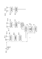
本実施の形態にかかる被験者管理システム1の説明に先立ち、一般的な被験者管理システム1の構成について説明する。図1は、一般的な被験者管理システム1の構成を示す概念図である。被験者管理システム1は、主に病院(大小を問わない)において構築されるものであり、アンテナ(ホイップアンテナや同軸漏洩ケーブル等)を用いてデータを送信するアンテナシステムである。
Prior to the description of the
被験者管理システム1は、受信機10、電源供給機20、集合器30−1〜30−6、増幅器40−1〜40−40−3、アンテナ50−1〜50−6を備える。また被験者管理システム1において、患者が携帯する医用テレメータ(医用送信機)60−1が使用される。各装置の使用数は、任意のものでよく、院内の構成に応じて適宜変更すればよい。同一名称でハイフン(“−”)に続く数字のみが異なる要素は、基本的に同一の機能や構成を有する。例えば集合器30−1と集合器30−2は、基本的に同一の機能や構成を有する。以下の説明において、ハイフン以下の記載を省略した場合、各装置に共通する機能や構成についての説明とする。
The
医用テレメータ60は、被験者のバイタルサイン(詳細には心電図波形、血圧、体温、動脈血酸素飽和度、等)を測定する装置である。医用テレメータ60は、ベッドサイドモニタであっても構わないものの、携帯可能な装置であることが好ましい。医用テレメータ60は、被験者が携帯しやすいように、ベルト等の身体に固定される手段に取り付けられていてもよい。医用テレメータ60は、通信範囲内にあるアンテナ50に対してバイタルサインの測定データと被験者の識別子等を関連付けたデータ(以下、生体データとも呼称する)を送信する。当該生体データは、ケーブル線を介して受信機10に送信される。
The medical telemeter 60 is a device that measures a vital sign (specifically, an electrocardiogram waveform, blood pressure, body temperature, arterial oxygen saturation, etc.) of a subject. The medical telemeter 60 may be a bedside monitor, but is preferably a portable device. The medical telemeter 60 may be attached to a means fixed to the body such as a belt so that the subject can easily carry it. The medical telemeter 60 transmits data (hereinafter also referred to as biometric data) in which vital sign measurement data is associated with the subject's identifier and the like to the antenna 50 within the communication range. The biological data is transmitted to the
受信機10は、医用テレメータ60から送信される生体データを受信する。受信機10は、限定はされないものの好適にはセントラルモニタである。受信機10は、複数の医用テレメータ60からの生体データを受信し、複数の被験者のバイタルサインの測定値や測定波形を備え付けのディスプレイに表示する。
The
複数個所に設置されたアンテナ50は、集合器30によって収束される。アンテナ50は、院内の一定範囲をカバーし、カバーする範囲内にある医用テレメータ60から送信された生体データを受信する。アンテナ50は、受信した生体データを集合器30及び増幅器40を介して受信機10に送信する。
The antennas 50 installed at a plurality of locations are converged by the aggregator 30. The antenna 50 covers a certain range in the hospital and receives biological data transmitted from the medical telemeter 60 within the covered range. The antenna 50 transmits the received biological data to the
集合器30は、各機器と接続したケーブル線を分配する。すなわち集合器30は、アンテナシステムの電気的接続を分岐させる。増幅器40(ブースター)は、アンテナ50から送信された生体データを示す信号を増幅して受信機10に向かって送信する。なお増幅器40は、電源供給機20からの電源供給を受けて動作する。
The aggregator 30 distributes cable lines connected to each device. That is, the collector 30 branches the electrical connection of the antenna system. The amplifier 40 (booster) amplifies the signal indicating the biological data transmitted from the antenna 50 and transmits the amplified signal toward the
電源供給機20は、院内の商用電源コンセントと接続し、増幅器40に対して電源供給を行う。例えば電源供給機20は、商用電源コンセントから供給されるAC電源(例えば100V)をDC電源(例えば15V)に変換する。そして電源供給機20は、同軸ケーブル線を介して変換したDC電源を増幅器40に供給する。
The
各機器の接続(アンテナ50〜集合器30、集合器30〜増幅器40、集合器30〜受信機10)は、例えば同軸ケーブル線により接続されている。当該同軸ケーブル線は、DC電源を各装置に給電可能な構成となっている。例えば同軸ケーブル線は、芯線をグランド線で覆うように構成されたケーブルである。同軸ケーブル線は、この二重構造により接続する各機器に対してDC電源を給電する。 The connections of each device (antenna 50 to collector 30, cluster 30 to amplifier 40, collector 30 to receiver 10) are connected by, for example, a coaxial cable line. The coaxial cable line is configured to be able to supply power to each device with a DC power source. For example, a coaxial cable line is a cable configured to cover a core line with a ground line. The coaxial cable supplies DC power to each device connected by this duplex structure.
被験者管理システム1において、医用テレメータ60から受信機10への各種データ(生体データを含む)の送信経路は以下のようになる。医用テレメータ60は、物理的な距離が近いアンテナ50に対してデータ(信号)を送信する。アンテナ50は、集合器30を介して増幅器40に対してデータ(信号)を供給する。増幅器40は、入力されたデータ(信号)を増幅した後に受信機10に対してデータ(信号)を送信する。
In the
以下、医用テレメータ60−1を例にとり生体データの送信処理を説明する。医用テレメータ60−1は、アンテナ50−1に対して生体データを送信する。アンテナ50−1は、ケーブル線及び集合器30−2を介して増幅器40−1に対して生体データを送信する。増幅器40−1は、生体データ(信号)を増幅し、ケーブル線及び集合器(30−3、30−1)を介して受信機10に送信する。受信機10は、受信した生体データを基にディスプレイ画面上に被験者の各種情報(バイタルサインの測定値や波形等)を表示する。
The biometric data transmission process will be described below using the medical telemeter 60-1 as an example. The medical telemeter 60-1 transmits biological data to the antenna 50-1. The antenna 50-1 transmits biological data to the amplifier 40-1 via the cable line and the collector 30-2. The amplifier 40-1 amplifies the biological data (signal) and transmits it to the
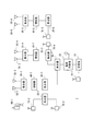
以上が一般的な被験者管理システム1の構成及び動作概念である。続いて本実施の形態にかかる被験者管理システム1の構成について説明する。図2は、本実施の形態にかかる被験者管理システム1の構成を示す概念図である。本実施の形態にかかる被験者管理システム1は、図1の構成に加えて送受信モジュール70−1〜70−5が設けられている。なお送受信モジュール70は、任意の数だけ配置すればよい。
The above is the configuration and operation concept of the general
送受信モジュール70は、アンテナシステム(アンテナ50と同軸ケーブル等から構成されるネットワークシステム)とは異なるネットワークを介してデータの送受信を行う。例えば送受信モジュール70は、ワイヤレスセンサネットワーク技術を応用して医用テレメータ60と受信機10との間のデータ送受信を実現する。
The transmission /
送受信モジュール70は、接続形態等は問わないものの、ワイヤレスセンサネットワークの技術を応用してデータ送信を行えばよい。当該ワイヤレスセンサネットワークの概念について図3を参照して説明する。
Although the transmission /
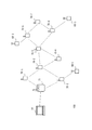
図3は、送受信モジュール70が構築するワイヤレスセンサネットワーク100の概念を示す図である。ワイヤレスセンサネットワーク100は、図2に示すアンテナシステム(ケーブル線により接続されたネットワーク)とはデータ送受信の観点で見ると独立したネットワークである。ワイヤレスセンサネットワーク100は、例えば6LoWPAN規格と802.15.4e規格に基づいて構成されたものであればよい(非特許文献1、非特許文献2等)。ワイヤレスセンサネットワーク100は、例えばTSMP(Time Synchronized Mesh Protocol)を利用すると共に、メッシュ型のトポロジーを採用したネットワークであればよい。
FIG. 3 is a diagram illustrating the concept of the
ワイヤレスセンサネットワーク100は、受信機10、送受信モジュール70−1〜70−8、マネージャ端末71、及び医用テレメータ60−1〜60−3によって構成される。なお送受信モジュール70や医用テレメータ60の個数は任意のものであれば良い。ワイヤレスセンサネットワーク100は、受信機10と医用テレメータ60−1〜60−3との間のデータ送受信に用いられる。
The
受信機10は、医用テレメータ60−1〜60−3の使用チャネル、製造番号、MACアドレス等の情報を管理する。すなわち受信機10は、ワイヤレスセンサネットワーク100に接続する医用テレメータ60の識別情報を管理する。医用テレメータ60は、使用開始時等にアンテナシステムとワイヤレスセンサネットワーク100を介して自身の識別情報を受信機10に送信する。
The
ワイヤレスセンサネットワーク100では、各医用テレメータ60と受信機10との間でのデータ送信が行われ、医用テレメータ60間でのデータ送信は行われない。そのためワイヤレスセンサネットワーク100は、受信機10をルートノードとするツリー構造とも解釈することができる。そのため、各医用テレメータ60や送受信モジュール70がネットワーク参加時等にルートノード方向(受信機10へのデータ送信方向)を認識することにより、医用テレメータ60から受信機10へのデータ送信が実現される。
In the
マネージャ端末71は、ワイヤレスセンサネットワーク100の接続情報を管理する装置である。マネージャ端末71の管理する接続情報の一例を図4に示す。マネージャ端末71は、各送受信モジュール70の接続関係を図4に示すように管理する。なお医用テレメータ60は、送受信モジュール70と同等の送受信機能を内部に実装する。そのためマネージャ端末71は、医用テレメータ60も送受信モジュール70の一種であるものとして接続情報を管理する。
The
新たな送受信モジュール70がワイヤレスセンサネットワーク100に参加する場合、新規参加する送受信モジュール70の直近に配置された送受信モジュール70を介して、マネージャ端末71に参加要求を送信する。マネージャ端末71は、参加要求に応じて接続情報(図4)を更新する。またマネージャ端末71は、新規に参加する送受信モジュール70にマネージャ端末71までの経路を通知してもよい。
When a new transmission /
医用テレメータ60が移動する場合、医用テレメータ60はマネージャ端末71に接続先の更新要求を送信する。マネージャ端末71は、当該更新要求に応じて接続情報(図4)を更新する。
When the medical telemeter 60 moves, the medical telemeter 60 transmits a connection destination update request to the
受信機10は、送信したいデータと、自身が管理する医用テレメータ60の識別情報と、をマネージャ端末71に送信する。マネージャ端末71は、識別情報と接続情報(図4)を基に送信経路を決定し、送信経路情報と送信したいデータを送信経路上にある送受信モジュール70に送信する。データ受信をした送受信モジュール70は、送信経路情報に従ってあて先となる医用テレメータ60までデータを転送する。
The
なお上述の通信方式はあくまでも一例であり、送受信モジュール70はアンテナを介さない任意のセンサネットワークによる通信を応用してもよい。また図3の例では、受信機10とマネージャ端末71が直接接続している構成としたが必ずしもこれに限られず、受信機10とマネージャ端末71が直接接続しない構成としてもよい。
Note that the above-described communication method is merely an example, and the transmission /
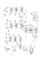
続いて被験者管理システム1内でのデータや電源供給の流れについて図5を参照して説明する。なお説明の簡素化のため、図5において上述のマネージャ端末71の記載は省略している。
Next, the flow of data and power supply in the
医用テレメータ60は、既存のアンテナシステムを用いて受信機10に対してデータ(第1データ)を送信する。ここで医用テレメータ60は、アンテナシステムを介してリアルタイム性が要求される生体データ(例えば被験者のバイタルサインの測定データであり、遅滞なく処理や表示されることが好ましいデータである。このリアルタイム性が要求されるデータを図5内ではリアルタイムデータとも呼称する。)を送信することが望ましい。例えば医用テレメータ60−1は、アンテナ50−1、集合器30−2、増幅器40−1、集合器30−3、集合器30−1を介してケーブル線経由で生体データを受信機10に送信する(図5一点鎖線)。
The medical telemeter 60 transmits data (first data) to the
このように医用テレメータ60がアンテナシステムを介して生体データを送信することにより、既存のアンテナシステムの用途や取り扱うデータ量をほとんど変えることなく、既存のアンテナシステムを利用できる。 As described above, when the medical telemeter 60 transmits the biological data via the antenna system, the existing antenna system can be used without changing the application of the existing antenna system or the amount of data to be handled.
受信機10は、送受信モジュール70を介して医用テレメータ60に対してデータ(第2データ)を送信する。例えば受信機10は、医用テレメータ60の動作制御(例えば各種バイタルサインの測定開始指示)を指示する情報(動作制御情報とも呼称する。)を送信する(図5二点鎖線)。例えば受信機10は、医用テレメータ60−1に対して非観血血圧測定の開始を指示する動作制御情報を送受信モジュール70−1、70−2、70−3経由で送信する。医用テレメータ60−1は、非観血血圧測定の指示を受けた場合、カフ(図示せず)による加圧を開始して測定を実行する。なお医用テレメータ60−1は、測定開始に先立って、「受信機10(医療従事者)の指示に従って血圧測定を開始します。」といった音声アナウンスを行っても構わない。
The
また医用テレメータ60は、送受信モジュール70を介して受信機10に対してデータ(第3データ)を送信する。ここで医用テレメータ60から送受信モジュール70を介して送信されるデータ(第3データ)の内容は特に限定されないものの、リアルタイム性が必要とされないデータ(非リアルタイムデータ)であることが好ましい。すなわちリアルタイム性が要求されるデータがアンテナシステムを介して送信され、リアルタイム性が要求されないデータが送受信モジュール70を介して送信されることが好ましい。これにより、既存のアンテナシステムの用途を変えることなく、双方向のデータ送信を行うことができる。
The medical telemeter 60 transmits data (third data) to the
例えば医用テレメータ60−1は、送受信モジュール70−3、70−2、70−1を介して受信機10に対して機器管理情報を送信する(図5二点鎖線)。機器管理情報とは、医用テレメータ60−1のバッテリ残量やセルフチェックの結果を含みうる情報である。医用テレメータ60−1は、所定の時間(例えば12時間毎)などに機器管理情報を受信機10に送信する。受信機10は機器管理情報を基に医用テレメータ60−1の状態が良好であるか否か(例えばバッテリ残量が30%以上であるか否か)を判定し、問題があればアラームの出力等を行う。
For example, the medical telemeter 60-1 transmits device management information to the
続いて電源供給の流れについて説明する。上述のようにアンテナシステム(アンテナ50やケーブル線)を介したデータ送信と、送受信モジュール70を介したデータ送受信と、は独立して動作する。しかしながら送受信モジュール70は、アンテナシステムのケーブル線と接続するように構成されている。例えば送受信モジュール70−2は、アンテナシステム内のケーブル線と接続し、当該ケーブル線を介して集合器30−7と接続している。電源供給機20は、上述のようにAC/DC電源変換を行った後に、DC電源をケーブル線を介して増幅器40に供給する(ケーブル線にDC電源を重畳送信して給電する)。この仕組みを利用し、送受信モジュール70は、ケーブル線を介してDC電源を給電する。例えば送受信モジュール70−2は、電源供給機20から供給されたDC電源を、集合器30−7から延伸するケーブル線を介して受電する(図5点線)。送受信モジュール70−2は、受電したDC電源により駆動する。すなわち送受信モジュール70−2は、バッテリや商用コンセントとの接続を行うことなく駆動することができる。
Next, the flow of power supply will be described. As described above, data transmission via the antenna system (antenna 50 or cable line) and data transmission / reception via the transmission /
なお送受信モジュール70を商用コンセントと接続することや、バッテリ駆動とすることも可能である。しかしながら送受信モジュール70は、設置場所やバッテリ切れの問題を回避するために電源供給機20から受電することが好ましい。電源供給機20は、院内の商用コンセントとして、病院設備の無停電電源(図に記載ない)に接続する。震災などでの緊急時に患者の生命状態を把握することは重要であり、病院が停電になった時、本システム全体が停止することを防止する。このように接続することによって、電源を一元管理でき安全に運用できる。
The transmission /
続いて本実施の形態にかかる被験者管理システム1の効果について説明する。医用テレメータ60は、既存のアンテナシステムを介してバイタルサインの測定データを含み得るデータ(第1データ)を受信機10に送信できる。また送受信モジュール70は、アンテナシステムとは異なるネットワークを介して医用テレメータ60と受信機10との双方向通信を可能とする。医用テレメータ60と受信機10は、この送受信モジュール70を利用してデータ(第2データ、第3データ)の送受信を行うことができる。これによりアンテナシステムの扱うデータ量の大幅な増加を回避できると共に、医用テレメータ60と受信機10の間での双方向通信を実現できる。
Next, effects of the
また送受信モジュール70は、アンテナシステムのケーブル線と物理的に接続する。アンテナシステム内の電源供給機20は、ケーブル線を介して電源を増幅器40及び送受信モジュール70に供給する構成としてもよい。これにより既存のアンテナシステムのケーブル線に送受信モジュール70を接続するのみで、送受信モジュール70の電源供給を行うことができる。
The transmission /
また受信機10は、医用テレメータ60に対して動作制御を指示する動作制御情報(例えば非観血血圧測定の開始を指示する情報)を送信できる。医用テレメータ60は、動作制御情報に応じた処理(例えば非観血血圧測定の開始)を行う。これにより医療従事者は、遠隔地にいながら被験者に対する適切な測定処理等を行うことができる。
Further, the
また医用テレメータ60は、送受信モジュール70を介して機器管理情報を送信する。すなわち医用テレメータ60は、自機の状態(バッテリ残量、セルフチェックによるエラーの有無、等)を受信機10に通知する。受信機10は、エラーとなっている(またはエラーの蓋然性が高い)医用テレメータ60に関する情報を表示等すればよい。これにより医療従事者は、遠隔地にいながら医用テレメータ60の異常を認識することができ、速やかな対応を行うことができる。
The medical telemeter 60 transmits device management information via the transmission /
なお、上述の被験者管理システム1を構成するアンテナ50はいわゆるホイップアンテナであったが、必ずしもこれに限られず、同軸漏洩ケーブルを用いたシステムであってもよい。図6は、同軸漏洩ケーブル51を用いた被験者管理システム1の構成を示すブロック図である。同軸漏洩ケーブル51は、院内の天井裏等に敷設される。同軸漏洩ケーブル51は、受信機10や増幅器40と接続しつつ、院内に張り巡らされる。同軸漏洩ケーブル51は、信号の伝送に伴い電波が漏れ出すという性質を有する。そのため同軸漏洩ケーブル51は、アンテナ50と同様の作用を奏する同軸ケーブルである(換言すると同軸漏洩ケーブル51はケーブルと一体化したアンテナの一種と考えることもできる)。図6において同軸漏洩ケーブル51を利用したデータの流れを一点鎖線で示している。医用テレメータ60は、同軸漏洩ケーブル51に対してデータを送信する。同軸漏洩ケーブル51は、受信したデータを伝送する。その他の構成は、図1の構成と同様である。同軸漏洩ケーブル51を使用した既存のアンテナシステムであっても、図1の構成と同様に集合器30による分岐先に送受信モジュール70を接続するのみで、容易に双方向通信を実現することができる。
In addition, although the antenna 50 which comprises the above-mentioned test
<実施の形態2>
本実施の形態にかかる被験者管理システム1は、更に電子カルテシステム200と接続していることを特徴とする。なお以下の説明において実施の形態1と同様の名称及び符号を付した処理部は、特に説明しない限り実施の形態1と同様の構成であるものとする(以降の実施形態についても同様である。)。
<Embodiment 2>
The
図7は、本実施の形態にかかる被験者管理システム1の構成を示すブロック図である。この被験者管理システム1は、図2の構成に加えてバイタルサイン測定端末72を更に有する。また受信機10は、電子カルテシステム200と接続(連携)している。
FIG. 7 is a block diagram showing a configuration of the
バイタルサイン測定端末72は、被験者のバイタルサインをスポット的(間欠的)に測定する端末である。病棟においては、全ての被験者(患者)が医用テレメータ60を携帯しているわけではなく、病態によっては医用テレメータ60を携帯しない被験者もいる。これらの被験者についても各種のバイタルサイン(例えば体温、血圧、動脈血酸素飽和度、)を測定したい場合がある。バイタルサイン測定端末72は、このような被験者のバイタルサインをスポット的に測定する端末である。
The vital
医用テレメータ60を携帯しない被験者は、腕等に氏名等と関連付けられたコードが埋め込まれたリストバンド等を携帯すればよい。バイタルサイン測定端末72は、被験者の携帯するコードを読み出すリーダと接続する。バイタルサイン測定端末72は、被験者の携帯するコードを読み出して受信機10に送信する。バイタルサイン測定端末72は、医用テレメータ60と同様に送受信モジュール70を介してデータを送受信する。
A subject who does not carry the medical telemeter 60 may carry a wristband or the like in which a code associated with a name or the like is embedded in an arm or the like. The vital
バイタルサイン測定端末72は、各種のバイタルサインを測定するためのプローブと接続可能な構成である。またバイタルサイン測定端末72は、各種のセンサ(例えば体温計)と近距離無線通信(ブルートゥース:登録商標)を介して接続可能な構成であってもよい。バイタルサイン測定端末72は、プローブを介して取得した生体信号からバイタルサインの測定データを算出する。
The vital
電子カルテシステム200は、診療行為の記録、各種バイタルサインの測定データの記録等を統合管理するシステムである。電子カルテシステム200は、被験者の識別情報と診療行為やバイタルサインの測定データを関連付けて管理している。
The electronic
以下、図7に示す被験者管理システム1の利用シナリオ例を説明する。
Hereinafter, a usage scenario example of the
被験者は、バイタルサイン測定端末72のリーダにリストバンドのコード(識別子)を読み込ませる。バイタルサイン測定端末72は、送受信モジュール70−2、70−1を介して読み出した識別子を受信機10に送信する。受信機10は、識別子を電子カルテシステム200に送信する。受信機10と電子カルテシステム200は、任意の接続形態(例えばLAN)により接続していればよい。
The subject causes the reader of the vital
電子カルテシステム200は、識別子を基に被験者の情報を読み出し、読み出した被験者情報(被験者の名前、性別、年齢、以前のバイタルサインの測定値等)を受信機10に送信する。受信機10は、送受信モジュール70−1及び70−2を介してバイタルサイン測定端末72に被験者情報を送信する。
The electronic
バイタルサイン測定端末72は、受信した被験者情報をディスプレイに表示する。これにより被験者は、自身のデータ測定を行うことや以前の測定値を把握することができる。
The vital
バイタルサイン測定端末72は、被験者の任意のバイタルサイン(例えば血圧や動脈血酸素飽和度)の測定を行う。バイタルサイン測定端末72は、送受信モジュール70−2、70−1を介してバイタルサインの測定結果を受信機10に送信する。受信機10は、受信した測定結果を電子カルテシステム200に送信する。
The vital
電子カルテシステム200は、受信した測定結果を被験者の識別子と関連付けて登録する。電子カルテシステム200は、登録(更新)が終了したことを受信機10に通知する。受信機10は、送受信モジュール70−1及び70−2を介して登録が終了したことをバイタルサイン測定端末72に通知する。
The electronic
バイタルサイン測定端末72は、登録が完了したことをディスプレイに表示する。これにより被験者は、無事に測定が完了したことを把握できる。
The vital
このようにバイタルサイン測定端末72は、スポット的に被験者のバイタルサインを測定し、送受信モジュール70を介してバイタルサインの測定データを受信機10(ひいては電子カルテシステム200)に送信する。すなわちアンテナシステムのデータ取扱量を増やすことなく、スポット的なバイタルサインの測定結果の送信を実現することができる。
In this way, the vital
また受信機10が電子カルテシステム200と接続することにより、電子カルテシステム200は、一元的な被験者のバイタルサイン測定の管理を行うことができる。
Further, when the
また電子カルテシステム200とバイタルサイン測定端末72との間で双方向通信が実現される。これにより被験者は、電子カルテシステム200から送信された情報(例えば登録が完了されたこと)を認識することができる。被験者は、登録完了通知を参照すること等により安心してシステムを利用することができる。
In addition, bidirectional communication is realized between the electronic
<実施の形態3>
本実施の形態にかかる被験者管理システム1は、受信機10から送受信モジュール70を介して医用テレメータ60以外の装置にデータを送信できることを特徴とする。以下、本実施の形態にかかる被験者管理システム1について実施の形態1と異なる点を説明する。
<Embodiment 3>
The
図8は、本実施の形態にかかる被験者管理システム1の動作概念を示すブロック図である。本実施の形態にかかる被験者管理システム1では、医療従事者が携帯端末80を携帯することを想定している。携帯端末80は、医用テレメータ60と同様に送受信モジュール70を介してデータの送受信を行う機能(モジュール)を内蔵している。
FIG. 8 is a block diagram showing an operation concept of the
医用テレメータ60は、実施の形態1と同様にアンテナシステムを介して生体データを送信する。受信機10は、受信した生体データの解析を行う。
The medical telemeter 60 transmits biological data via the antenna system as in the first embodiment. The
受信機10は、所定条件を満たす場合に、携帯端末80に向けて被験者に関するデータを送信する。ここで所定条件とは、被験者の状態を示すデータ(以下、被験者状態情報とも呼称する。)を医療従事者に通知したほうが良いと思われる条件を規定するものである。例えば所定条件には、「被験者の生体情報(バイタルサインの測定値や測定波形)を解析した際に異常を検出した場合(例えばアラーム状態となった場合)」、「被験者の状態を通知してから一定時間が経過した場合(前回の通知から一定時間が経過した場合)」、「所定の時刻となった場合」等が挙げられる。これらの所定条件は、医療従事者が適宜設定できるようにしても構わない。
The
受信機10は、所定条件を満たす状態となった場合、送受信モジュール70を介して被験者状態情報を携帯端末80に送信する。被験者状態情報とは、被験者のバイタルサインの測定値や測定波形そのものであってもよく、検出されたアラーム状態に関連づいた情報(例えば「Aさんが不整脈です。」といったメッセージ)であってもよい。
The
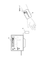
図9は、携帯端末80の使用イメージを示す概念図である。携帯端末80には、受信機10から送信された被験者状態情報が表示される。ここで表示される被験者状態情報は、図示するように「Aさん不整脈」といったアラームメッセージであってもよく、被験者の各種バイタルサイン(血圧、心拍数、動脈血酸素飽和度、呼吸数、等)の測定値や測定波形が表示されてもよい。またアラームメッセージを表示する際には、携帯端末80はアラーム音を合わせて出力してもよい。
FIG. 9 is a conceptual diagram showing a usage image of the
医療従事者は、遠隔地にいる場合であっても携帯端末80を参照することにより被験者の状態を把握することができる。これにより医療従事者は、被験者の容態が急変したこと等を遠隔地にいる場合であっても認識することができる。
The medical staff can grasp the state of the subject by referring to the
また受信機10は、被験者の各種情報(主にバイタルサインの測定値や測定波形)にアクセスするための識別コード(例えば図示するような記号の識別コード)を合わせて携帯端末80に送信してもよい。携帯端末80は、受信した識別コードを図示するように表示画面上に表示する。
The
院内には複数の表示装置90(図8には図示せず)が配置されている。表示装置90は、受信機10とネットワーク(例えばLAN(Local Area Network))経由で接続する装置である。表示装置90は、識別コードの読み出しを行う読み出しユニット91と接続(または一体化)している。読み出しユニット91は、バーコードリーダやQRコードリーダ等である。医療従事者は、識別コードを表示装置90の読み出しユニット91に読み取らせる。
A plurality of display devices 90 (not shown in FIG. 8) are arranged in the hospital. The
表示装置90は、読み出した識別コードをネットワーク経由で受信機10に送信する。受信機10は、当該識別コードに対応した被験者の各種情報(被験者名、年齢、性別、バイタルサインの測定値、バイタルサインの測定波形、等)を表示装置90に送信する。表示装置90は、受信した被験者の各種情報をディスプレイに表示する。表示装置90は、例えば一般的なセントラルモニタやベッドサイドモニタと同様の形態で表示を行えばよい。
The
医療従事者は、この表示画面(図9)を参照することにより、被験者の詳細情報を把握することができる。なお表示装置90は、院内に複数設置されていることが好ましい。これにより医療従事者は、被験者の居る病室が遠い場合であっても、速やかに近くの表示装置90から被験者の状態を認識することができる。
The medical staff can grasp the detailed information of the subject by referring to the display screen (FIG. 9). A plurality of
なお図9では、携帯端末80がリストバンド型の機器であるものとしたが必ずしもこれに限られない。携帯端末80は、医療従事者が携帯可能な任意の装置であればよい。
In FIG. 9, the
続いて本実施の形態にかかる被験者管理システム1の効果について説明する。受信機10は、被験者の状態を通知したほうが良い条件(所定条件)を満たした場合、医療従事者の携帯する携帯端末80に被験者状態情報を通知する。例えば被験者が不整脈を起こしている場合に、受信機10は「Aさん不整脈」といった被験者状態情報を携帯端末80に送信する。これにより医療従事者は、遠隔地にいる場合であっても被験者の異常等を正確に把握できるようになる。また受信機10は、送受信モジュール70を介して被験者状態情報を送信するため、アンテナシステムの情報量を増加させることなく通知を行うことができる。
Next, effects of the
通知のタイミングを規定する所定条件には、被験者がアラーム状態となった場合、所定時間になった場合、前回の通知から所定時間が経過した場合、を含む。アラーム状態となった際に通知する場合、医療従事者は遠隔地にいても被験者の異常を把握することができる。また所定時刻や所定時間経過時に通知を行う場合、医療従事者は遠隔地にいても被験者の状態の定期的な点検を行うことができる。 The predetermined condition that defines the timing of notification includes a case where the subject is in an alarm state, a predetermined time is reached, and a predetermined time has elapsed since the previous notification. When notifying when an alarm state occurs, the medical staff can grasp the abnormality of the subject even in a remote place. In addition, when a notification is given when a predetermined time or a predetermined time elapses, a medical worker can periodically check the condition of the subject even in a remote place.
また図9に示すように、被験者状態情報には被験者のバイタルサインにアクセス可能な識別コードが含まれていてもよい。医療従事者は、この識別コードを用いることにより表示装置90に被験者のバイタルサインを表示させることができる。これにより医療従事者は、被験者のバイタルサインの測定値や測定波形を大画面で確認することができる。
As shown in FIG. 9, the subject state information may include an identification code that can access the vital sign of the subject. The medical staff can display the vital sign of the subject on the
なお受信機10は、異常検出に応じて被験者状態情報を送信する場合、当該被験者の担当の医療従事者の端末を特定したのちに被験者状態情報を送信しても良い。この場合、受信機10は、医療従事者と被験者の対応関係を予め管理しておけばよい。例えば受信機10は、被験者のAさんと医療従事者のXさんを対応付ける関係を管理しておけばよい。
In addition, when transmitting the subject state information in response to the abnormality detection, the
以上、本発明者によってなされた発明を実施の形態に基づき具体的に説明したが、本発明は既に述べた実施の形態に限定されるものではなく、その要旨を逸脱しない範囲において種々の変更が可能であることはいうまでもない。 As mentioned above, the invention made by the present inventor has been specifically described based on the embodiments. However, the present invention is not limited to the embodiments already described, and various modifications can be made without departing from the scope of the invention. It goes without saying that it is possible.
1 被験者管理システム
10 受信機
20 電源供給機
30 集合器
40 増幅器
50 アンテナ
60 医用テレメータ
70 送受信モジュール
80 携帯端末
90 表示装置
1
Claims (9)
前記アンテナシステムを介して前記第1データを受信する受信機と、
前記アンテナシステムとは異なるネットワークを介してデータを送受信する送受信モジュールと、を備え、
前記送受信モジュールは、前記受信機から出力された第2データを受信して前記医用送信機に送信すると共に、前記医用送信機から第3データを受信して前記受信機に送信する、
被験者管理システム。 A medical transmitter for measuring a vital sign of a subject and transmitting first data, which may include measurement data of the vital sign, via an antenna system;
A receiver for receiving the first data via the antenna system;
A transmission / reception module for transmitting and receiving data via a network different from the antenna system,
The transceiver module receives the second data output from the receiver and transmits the second data to the medical transmitter, and receives third data from the medical transmitter and transmits the third data to the receiver.
Subject management system.
前記送受信モジュールは、前記ケーブル線に接続し、前記電源供給機からの給電を受けて動作する、
ことを特徴とする請求項1に記載の被験者管理システム。 The antenna system includes an amplifier that amplifies the first data, and a power supply that feeds power to the amplifier via a cable line,
The transmission / reception module is connected to the cable line and operates by receiving power from the power supply unit.
The subject management system according to claim 1.
前記医用送信機は、前記動作制御情報に応じた動作を行う、
ことを特徴とする請求項1または請求項2に記載の被験者管理システム。 The second data includes operation control information for instructing operation control of the medical transmitter,
The medical transmitter performs an operation according to the operation control information;
The subject management system according to claim 1 or 2, characterized in that
前記受信機は、前記機器管理情報に基づいて前記医用送信機の機器の異常を検出する、
ことを特徴とする請求項1〜3のいずれか1項に記載の被験者管理システム。 The third data includes device management information indicating a state of the device of the medical transmitter,
The receiver detects an abnormality of the device of the medical transmitter based on the device management information;
The subject management system according to any one of claims 1 to 3, wherein
前記バイタルサイン測定端末は、間欠的に測定した被験者のバイタルサインの測定データを前記受信機に送信する、
ことを特徴とする請求項1〜4のいずれか1項に記載の被験者管理システム。 Further comprising a vital sign measurement terminal for transmitting and receiving data to and from the receiver via the transceiver module;
The vital sign measurement terminal transmits measurement data of the vital sign of the subject measured intermittently to the receiver.
The subject management system according to any one of claims 1 to 4, wherein
前記受信機は、前記バイタルサイン測定端末から送信されたバイタルサインの測定データを前記電子カルテシステムに登録すると共に、前記送受信モジュールを介して前記電子カルテシステムから出力された情報を前記バイタルサイン測定端末に送信する、
ことを特徴とする請求項5に記載の被験者管理システム。 The receiver is connected to an electronic medical record system,
The receiver registers the vital sign measurement data transmitted from the vital sign measurement terminal in the electronic medical record system, and transmits information output from the electronic medical record system via the transmission / reception module to the vital sign measurement terminal. Send to
The subject management system according to claim 5.
ことを特徴とする請求項1〜6のいずれか1項に記載の被験者管理システム。 The receiver transmits subject state information indicating the state of the subject via the transmission / reception module to a portable terminal carried by a medical worker when a predetermined condition is satisfied,
The test subject management system according to any one of claims 1 to 6, wherein
ことを特徴とする請求項7に記載の被験者管理システム。 The predetermined condition includes a case where an abnormality is detected in the subject by analyzing the biological information of the subject, a case where a predetermined time has elapsed, and a case where a predetermined time has elapsed since the previous notification to the mobile terminal.
The subject management system according to claim 7.
前記被験者管理システムは、前記受信機と接続すると共に、前記識別コードを読み出した際に前記被験者の情報を前記受信機から読み出して表示する表示装置、を更に備える、
ことを特徴とする請求項7または請求項8に記載の被験者管理システム。 The subject status information includes an identification code for accessing various information of the subject,
The subject management system further includes a display device that is connected to the receiver and that reads and displays the subject information from the receiver when the identification code is read.
The subject management system according to claim 7 or 8, wherein
Priority Applications (1)
| Application Number | Priority Date | Filing Date | Title |
|---|---|---|---|
| JP2016026378A JP6694727B2 (en) | 2016-02-15 | 2016-02-15 | Subject management system |
Applications Claiming Priority (1)
| Application Number | Priority Date | Filing Date | Title |
|---|---|---|---|
| JP2016026378A JP6694727B2 (en) | 2016-02-15 | 2016-02-15 | Subject management system |
Publications (2)
| Publication Number | Publication Date |
|---|---|
| JP2017143917A true JP2017143917A (en) | 2017-08-24 |
| JP6694727B2 JP6694727B2 (en) | 2020-05-20 |
Family
ID=59680389
Family Applications (1)
| Application Number | Title | Priority Date | Filing Date |
|---|---|---|---|
| JP2016026378A Active JP6694727B2 (en) | 2016-02-15 | 2016-02-15 | Subject management system |
Country Status (1)
| Country | Link |
|---|---|
| JP (1) | JP6694727B2 (en) |
Cited By (2)
| Publication number | Priority date | Publication date | Assignee | Title |
|---|---|---|---|---|
| CN109283557A (en) * | 2018-08-21 | 2019-01-29 | 浙江大学 | Round trip pseudo-code subcarrier high-precision intersatellite ranging system and method |
| JP2020156852A (en) * | 2019-03-27 | 2020-10-01 | 日本光電工業株式会社 | Medical telemeter system |
Citations (9)
| Publication number | Priority date | Publication date | Assignee | Title |
|---|---|---|---|---|
| JP2001078974A (en) * | 1999-09-13 | 2001-03-27 | Nippon Koden Corp | Communication system for biological signal or the like |
| JP2002224053A (en) * | 2001-02-05 | 2002-08-13 | Next:Kk | Remote medical control system |
| KR20040008160A (en) * | 2001-04-23 | 2004-01-28 | 카디오네트, 인코포레이티드 | Medical monitoring system having multipath communications capability |
| WO2004066834A1 (en) * | 2003-01-31 | 2004-08-12 | Medtronic, Inc. | Patient monitoring device with multi-antenna receiver |
| JP2004358232A (en) * | 2003-05-15 | 2004-12-24 | Seiko Instruments Inc | Biological information measuring system, method of specifying biological information detecting device in use, recording medium recording the method of specifying biological information detecting device in use, portable device, and data collecting device |
| JP2005267364A (en) * | 2004-03-19 | 2005-09-29 | Asahi Kasei Medical Co Ltd | Medical treatment supporting system |
| US20070276270A1 (en) * | 2006-05-24 | 2007-11-29 | Bao Tran | Mesh network stroke monitoring appliance |
| JP2012086003A (en) * | 2010-09-21 | 2012-05-10 | Nippon Koden Corp | Medical telemetry system and medical telemeter |
| WO2013070779A2 (en) * | 2011-11-09 | 2013-05-16 | Telcare, Inc. | Handheld blood glucose monitoring device with messaging capability |
-
2016
- 2016-02-15 JP JP2016026378A patent/JP6694727B2/en active Active
Patent Citations (9)
| Publication number | Priority date | Publication date | Assignee | Title |
|---|---|---|---|---|
| JP2001078974A (en) * | 1999-09-13 | 2001-03-27 | Nippon Koden Corp | Communication system for biological signal or the like |
| JP2002224053A (en) * | 2001-02-05 | 2002-08-13 | Next:Kk | Remote medical control system |
| KR20040008160A (en) * | 2001-04-23 | 2004-01-28 | 카디오네트, 인코포레이티드 | Medical monitoring system having multipath communications capability |
| WO2004066834A1 (en) * | 2003-01-31 | 2004-08-12 | Medtronic, Inc. | Patient monitoring device with multi-antenna receiver |
| JP2004358232A (en) * | 2003-05-15 | 2004-12-24 | Seiko Instruments Inc | Biological information measuring system, method of specifying biological information detecting device in use, recording medium recording the method of specifying biological information detecting device in use, portable device, and data collecting device |
| JP2005267364A (en) * | 2004-03-19 | 2005-09-29 | Asahi Kasei Medical Co Ltd | Medical treatment supporting system |
| US20070276270A1 (en) * | 2006-05-24 | 2007-11-29 | Bao Tran | Mesh network stroke monitoring appliance |
| JP2012086003A (en) * | 2010-09-21 | 2012-05-10 | Nippon Koden Corp | Medical telemetry system and medical telemeter |
| WO2013070779A2 (en) * | 2011-11-09 | 2013-05-16 | Telcare, Inc. | Handheld blood glucose monitoring device with messaging capability |
Cited By (3)
| Publication number | Priority date | Publication date | Assignee | Title |
|---|---|---|---|---|
| CN109283557A (en) * | 2018-08-21 | 2019-01-29 | 浙江大学 | Round trip pseudo-code subcarrier high-precision intersatellite ranging system and method |
| JP2020156852A (en) * | 2019-03-27 | 2020-10-01 | 日本光電工業株式会社 | Medical telemeter system |
| JP7208843B2 (en) | 2019-03-27 | 2023-01-19 | 日本光電工業株式会社 | medical telemetry system |
Also Published As
| Publication number | Publication date |
|---|---|
| JP6694727B2 (en) | 2020-05-20 |
Similar Documents
| Publication | Publication Date | Title |
|---|---|---|
| US8897198B2 (en) | Medical device wireless network architectures | |
| US9398852B2 (en) | Medical telemetry system and medical telemeter | |
| US20090273467A1 (en) | Ip based monitoring and alarming | |
| CN104012127A (en) | Wireless relay module having emergency call functionality | |
| ATE461656T1 (en) | WIRELESS ECG DEVICE | |
| RU2015129549A (en) | COMBINING DEFIBRILLATOR DATA WITH PATIENT MONITOR | |
| Motika et al. | Wireless fetal heartbeat monitoring system using ZigBee and IEEE 802.15. 4 standard | |
| JP6694727B2 (en) | Subject management system | |
| US20090306934A1 (en) | Instrument monitoring system | |
| JP5877911B2 (en) | Wireless relay module for monitoring network status | |
| Fernández-López et al. | HM4All: A vital signs monitoring system based in spatially distributed ZigBee networks | |
| WO2020133521A1 (en) | Recovery monitoring system and method for hospitalized patient, and storage medium | |
| KR100866553B1 (en) | The ubiquitous sensor network nursing management system and the method | |
| US10881296B2 (en) | Measuring device and transmission method | |
| JP2008536564A (en) | A wireless patient monitoring system | |
| JPH1071128A (en) | Patient monitoring system | |
| JP7118695B2 (en) | Biological information monitoring system | |
| US20210337608A1 (en) | Sensor data quality as a trigger to check on-body presence and facilitate un-pairing | |
| Gonnot et al. | Sensor network for extended health monitoring of hospital patients | |
| JP2019107454A (en) | Medical system | |
| AU2021101362A4 (en) | A Wireless Networking of Medical Equipment’s on Mobile Application for Paperless Clinic | |
| KR102610503B1 (en) | Method, system and non-transitory computer-readable recording medium for supporting wireless interworking of devices | |
| JP7208843B2 (en) | medical telemetry system | |
| KR20080082025A (en) | Device for guiding a wireless health care process | |
| Chi et al. | A remote moniotring patient Homecare Gateway supporting streaming vital sign monitoring |
Legal Events
| Date | Code | Title | Description |
|---|---|---|---|
| A621 | Written request for application examination |
Free format text: JAPANESE INTERMEDIATE CODE: A621 Effective date: 20190108 |
|
| A977 | Report on retrieval |
Free format text: JAPANESE INTERMEDIATE CODE: A971007 Effective date: 20191031 |
|
| A131 | Notification of reasons for refusal |
Free format text: JAPANESE INTERMEDIATE CODE: A131 Effective date: 20191113 |
|
| A521 | Request for written amendment filed |
Free format text: JAPANESE INTERMEDIATE CODE: A523 Effective date: 20191119 |
|
| TRDD | Decision of grant or rejection written | ||
| A01 | Written decision to grant a patent or to grant a registration (utility model) |
Free format text: JAPANESE INTERMEDIATE CODE: A01 Effective date: 20200403 |
|
| A61 | First payment of annual fees (during grant procedure) |
Free format text: JAPANESE INTERMEDIATE CODE: A61 Effective date: 20200420 |
|
| R150 | Certificate of patent or registration of utility model |
Ref document number: 6694727 Country of ref document: JP Free format text: JAPANESE INTERMEDIATE CODE: R150 |
|
| R250 | Receipt of annual fees |
Free format text: JAPANESE INTERMEDIATE CODE: R250 |
|
| R250 | Receipt of annual fees |
Free format text: JAPANESE INTERMEDIATE CODE: R250 |