JP2017141013A - Air craft rotor blade having shape adapted for improvements on acoustic issue during flyby and performances during hovering and forward flights - Google Patents
Air craft rotor blade having shape adapted for improvements on acoustic issue during flyby and performances during hovering and forward flights Download PDFInfo
- Publication number
- JP2017141013A JP2017141013A JP2016238613A JP2016238613A JP2017141013A JP 2017141013 A JP2017141013 A JP 2017141013A JP 2016238613 A JP2016238613 A JP 2016238613A JP 2016238613 A JP2016238613 A JP 2016238613A JP 2017141013 A JP2017141013 A JP 2017141013A
- Authority
- JP
- Japan
- Prior art keywords
- blade
- segment
- twist
- range
- distance
- Prior art date
- Legal status (The legal status is an assumption and is not a legal conclusion. Google has not performed a legal analysis and makes no representation as to the accuracy of the status listed.)
- Granted
Links
Images


Classifications
-
- B—PERFORMING OPERATIONS; TRANSPORTING
- B64—AIRCRAFT; AVIATION; COSMONAUTICS
- B64C—AEROPLANES; HELICOPTERS
- B64C27/00—Rotorcraft; Rotors peculiar thereto
- B64C27/32—Rotors
- B64C27/46—Blades
- B64C27/467—Aerodynamic features
-
- B—PERFORMING OPERATIONS; TRANSPORTING
- B64—AIRCRAFT; AVIATION; COSMONAUTICS
- B64C—AEROPLANES; HELICOPTERS
- B64C27/00—Rotorcraft; Rotors peculiar thereto
- B64C27/04—Helicopters
-
- B—PERFORMING OPERATIONS; TRANSPORTING
- B64—AIRCRAFT; AVIATION; COSMONAUTICS
- B64C—AEROPLANES; HELICOPTERS
- B64C27/00—Rotorcraft; Rotors peculiar thereto
- B64C27/32—Rotors
- B64C27/46—Blades
- B64C27/463—Blade tips
-
- B—PERFORMING OPERATIONS; TRANSPORTING
- B64—AIRCRAFT; AVIATION; COSMONAUTICS
- B64C—AEROPLANES; HELICOPTERS
- B64C27/00—Rotorcraft; Rotors peculiar thereto
- B64C27/32—Rotors
- B64C27/46—Blades
- B64C27/473—Constructional features
Abstract
Description
関連出願の相互参照
本出願は2015年12月21日に出願されたFR第15 02660号の利益を主張し、その開示内容は本明細書に参照によって完全な形で組み込まれる。
CROSS REFERENCE TO RELATED APPLICATIONS This application claims the benefit of
発明の分野
本発明は、揚力を生成する翼型表面の分野に関し、詳細には、回転翼を形成する翼型表面に関する。
The present invention relates to the field of airfoil surfaces that generate lift, and in particular, to airfoil surfaces that form rotor blades.
本発明は、回転翼航空機のロータのブレードに関し、および少なくとも2つのそのようなブレードを有するロータに関する。ブレードはより詳細には、回転翼航空機に揚力を、および場合によっては推進力を与えるように、主ロータ用として意図されている。 The present invention relates to rotor blades for rotorcraft and to a rotor having at least two such blades. The blades are more particularly intended for the main rotor to provide lift and possibly propulsion to the rotorcraft.
従来、ブレードは、ロータの回転ハブに結合するための第1端部から、「自由」端部と称される第2端部まで、その翼長に沿って長手方向に延在する。ロータに関して、ブレードは第1端部から第2端部に向かって翼長方向において半径方向に延在することを理解することができる。さらに、ブレードは前縁からブレードの後縁に向かってブレードの弦に沿って横方向に延在する。 Traditionally, a blade extends longitudinally along its blade length from a first end for coupling to the rotor's rotating hub to a second end referred to as the “free” end. With respect to the rotor, it can be seen that the blades extend radially in the blade length direction from the first end to the second end. In addition, the blade extends laterally along the blade chord from the leading edge to the trailing edge of the blade.
従ってブレードはロータの回転ハブによって回転式に駆動される。従ってハブの回転軸はブレードの回転軸に一致する。 The blade is therefore driven rotationally by the rotating hub of the rotor. Therefore, the rotation axis of the hub coincides with the rotation axis of the blade.
第1端部は概ね以下で用語「ブレード基端」と称される一方、自由な第2端部は用語「ブレード先端」と称される。 The first end is generally referred to below as the term “blade proximal end”, while the free second end is referred to as the term “blade tip”.
動作中、ロータの各ブレードは、ロータの回転運動の間、空気力に曝され、特に、空力的揚力に曝され、その力は航空機に揚力を、または実際には推進力を提供する働きをする。 In operation, each blade of the rotor is exposed to aerodynamic forces during the rotor's rotational movement, and in particular, it is exposed to aerodynamic lift, which acts to provide lift, or indeed propulsion to the aircraft. To do.
このため、ブレードは、ブレード基端とブレード先端の間に配置された翼型部分を有する。この翼型部分は、翼長方向に沿った一連の翼型プロファイルによって構成され、この翼型プロファイルは以下で簡潔にするために「プロファイル」としばしば称される。各プロファイルは、翼長方向に対して概ね垂直な横断面内に配置され、ブレードの区切りを画定し、翼型部分の基端とブレード先端との間に配置される。翼型部分はブレードの揚力の実質的に全てを提供する。 For this reason, the blade has an airfoil portion disposed between the blade proximal end and the blade distal end. This airfoil portion is constituted by a series of airfoil profiles along the length of the airfoil, which are often referred to as “profiles” for the sake of simplicity below. Each profile is disposed in a cross section generally perpendicular to the blade length direction, defines a blade break, and is disposed between the proximal end of the airfoil portion and the blade tip. The airfoil portion provides substantially all of the blade lift.
ブレード基端と、翼型部分の基端との間の移行領域の形状は、制限部分を作製することによって、およびブレードに関連する構造的制限部分によって、概ね与えられる。ブレード基端と翼型部分の基端との間のこの移行領域は、用語「ブレード付け根」と称される場合があり、その空気力学性能は翼型部分の空気力学性能よりもはるかに低い。従って翼型部分の基端は、ブレード付け根の近くで、ブレード基端とブレード先端との間に配置される。この移行領域はそれにもかかわらずいくらかの揚力を生成し得る。加えて、この移行領域は、ロータのハブの近くに配置されているが、それにもかかわらず、その空気力学的な形状と無関係に、ブレードの全揚力に対しいくらかのわずかな寄与を提供する。 The shape of the transition region between the blade proximal end and the proximal end of the airfoil portion is generally provided by making the limiting portion and by the structural limiting portion associated with the blade. This transition region between the blade proximal end and the airfoil portion proximal end may be referred to as the term “blade root” and its aerodynamic performance is much lower than the aerodynamic performance of the airfoil portion. Accordingly, the proximal end of the airfoil portion is disposed between the blade proximal end and the blade distal end near the blade root. This transition region can nevertheless generate some lift. In addition, this transition region is located near the hub of the rotor, but nevertheless provides some slight contribution to the total lift of the blade, regardless of its aerodynamic shape.
例えば、翼型部分のブレードの区切りのプロファイルは、理想的にはゼロ厚さの薄い後縁によって特徴付けられる一方、ブレード基端の近くの、およびブレード基端と翼型部分の基端との間の移行領域の近くの後縁は厚く、場合によっては丸みを帯びている。 For example, the blade break profile of the airfoil portion is ideally characterized by a thin trailing edge of zero thickness, while near the blade proximal end and between the blade proximal end and the airfoil proximal end. The trailing edge near the transition area between them is thick and sometimes rounded.
回転翼航空機は、巡航飛行の間の高い前進速度、および非常に低い前進速度の両方で飛行できるという利点を提供し、それはホバリング飛行を実行することもできる。従って回転翼航空機は、狭い面積の領域に、従って例えば人の居住地域により近い領域に着陸できる、または実際には着陸用デッキまたはパッドに着陸できるという利点を提供する。 A rotary wing aircraft offers the advantage of being able to fly at both high forward speeds during cruise flights and very low forward speeds, which can also perform hovering flights. Thus, a rotary wing aircraft offers the advantage of being able to land in a small area, and thus for example in a region closer to a person's residential area, or in fact, can land on a landing deck or pad.
それにもかかわらず、高速での前進飛行は、ブレードが、非常に低い前進速度での飛行におよびホバリング飛行に必要な特性と異なり得る、またはそのような特性にとって望ましくない場合さえある空気力学特性を有することを必要とする。 Nevertheless, forward flight at high speeds has aerodynamic characteristics that the blades may differ from, or even undesirable for, the characteristics required for flying at very low forward speeds and for hovering flights. You need to have.
同様に、ブレードの空気力学特性は、ブレードによって発せられる騒音にも影響を及ぼす。そのような騒音は、居住地域に近いという理由で接近および着陸段階の間に問題になることもある。さらに、厳しい音響認定基準によって、回転翼航空機が従うことを要求される音響レベルが策定される。 Similarly, the aerodynamic characteristics of the blade also affect the noise emitted by the blade. Such noise can be a problem during the approach and landing phase because it is close to the residential area. In addition, strict acoustic qualification standards define the sound levels that a rotorcraft will be required to follow.
翼型プロファイルの予め決められた選択について、高速での前進飛行の間、およびホバリング飛行の間、ブレードの空気力学性能に、および同じくブレードの音響特性に影響を及ぼすブレードの幾何学的特徴は、特に、ブレードの区切りの翼型プロファイルの弦によって、ブレードのスイープ(sweep)によって、およびブレードのねじれによって構成される。 For a predetermined choice of airfoil profile, during high-speed forward flight and during hovering flight, the blade geometry, which also affects the blade aerodynamic performance, and also the blade acoustic properties, is: In particular, it is constituted by the strings of the airfoil profile of the blade break, by the sweep of the blade, and by the twist of the blade.
弦はあるブレード区切りのプロファイルの前縁と後縁との間の距離であることを思い起こされたい。この弦はブレードの翼長に沿って変化し得る。用語「テーパ」はブレードの翼長に沿って進む弦の低減を指すために一般に使用されるが、この用語はまた、ブレードの翼長に沿った弦の増大を指すこともできる。 Recall that the chord is the distance between the leading and trailing edges of a bladed profile. This string can vary along the blade length. The term “taper” is commonly used to refer to the reduction of the chord that travels along the blade length of the blade, but the term can also refer to the increase of the chord along the blade length of the blade.
スイープは、ブレードの前縁と、ブレードの特定の軸とによって形成される角度として定義され得る。慣例によって、前方スイープを有する領域において、前縁は、ロータの回転方向において正である、前記ブレード軸に対するスイープ角度を形成する一方で、後方スイープを有する領域において、前縁は、負である、前記ブレード軸に対するスイープ角度を形成する。前記ブレード軸は一般にブレードのピッチまたはフェザリング軸と一致する。 A sweep can be defined as the angle formed by the leading edge of the blade and a particular axis of the blade. By convention, in regions with a forward sweep, the leading edge forms a sweep angle with respect to the blade axis that is positive in the direction of rotation of the rotor, while in regions with a backward sweep, the leading edge is negative. A sweep angle with respect to the blade axis is formed. The blade axis generally coincides with the blade pitch or feathering axis.
ブレードのねじれは、ブレードの翼長に沿ってブレードの区切りのプロファイルの設定を変えることである。用語「設定」は、ブレードの区切りの各プロファイルの弦と、ブレードの基準面との間に形成される角度を指し、この角度は「ねじれ」角度と称される。例として、基準面は、ブレードの回転軸に対して垂直でありかつ前記ブレード軸を含む面であり得る。 Blade twisting is changing the setting of the blade break profile along the blade length. The term “setting” refers to the angle formed between the chord of each profile of the blade break and the reference plane of the blade, and this angle is referred to as the “twist” angle. As an example, the reference plane may be a plane that is perpendicular to and includes the blade axis.
用語「ねじれの関係性」は、ねじれ角度がブレードの翼長に沿って変化する程度を指す。従来のやり方では、ねじれは、ブレードの区切りプロファイルの前縁が前記基準面よりも低いとき、負として測定される。 The term “twist relationship” refers to the extent to which the twist angle varies along the blade length of the blade. In a conventional manner, twist is measured as negative when the leading edge of the blade break profile is lower than the reference plane.
発明の背景
高速前進飛行に関するブレードの性能、およびホバリング飛行に関するブレードの性能、ならびに接近段階の間のブレードの音響性能を独立して改善するための有効な解決策が知られている。
BACKGROUND OF THE INVENTION Effective solutions are known for independently improving blade performance for fast forward flight, and blade performance for hovering flight, and blade acoustic performance during the approach phase.
例えば、ホバリング飛行に関するブレードの空気力学性能を改善することは、ロータ揚力を変えないようにブレードによって引かれる力を低減することによって特徴付けられる。この改善は、ブレードの形状に対する受身的な変化によって、特にそのねじれを増大することによって、得ることができる。 For example, improving the aerodynamic performance of the blade for hovering flight is characterized by reducing the force drawn by the blade so as not to change the rotor lift. This improvement can be obtained by passive changes to the shape of the blade, in particular by increasing its twist.
ブレードのねじれの適切な増大は、揚力を、ブレードの、結果としてロータの表面領域全体にわたってより均一に分散することを可能にし、それによりホバリング飛行中、ロータの各ブレードによって吸収される動力を低減することを可能にする。増大するねじれは前記基準面に対して前縁を下げることであり、および、翼長に応じた空気流の円周速度の変化のために、ブレード基端に向かってよりもブレード先端に向かってそれを行うことであることを思い起こされたい。ホバリング飛行中のブレードの空気力学性能は、特に、ブレードの翼長に沿って誘発される速度をこのようなやり方でより均一にすることによって増大される。 Proper increase in blade twist allows the lift to be more evenly distributed across the blade, and consequently the entire surface area of the rotor, thereby reducing the power absorbed by each blade of the rotor during hovering flight Make it possible to do. Increasing twist is lowering the leading edge relative to the reference plane, and due to changes in the circumferential velocity of the air flow as a function of blade length, toward the blade tip rather than toward the blade proximal end Recall that it is to do it. The aerodynamic performance of the blade during hovering flight is increased, in particular, by making the speed induced along the blade wing length more uniform in this manner.
それにもかかわらず、回転翼航空機が高速で移動するとき、多量のブレードのねじれは、「前進」ブレードとして当業者に知られるアジマス位置にあるブレードのために、ブレード先端が負の揚力を有することに、すなわち、重力と同じ方向に存在する揚力を発生することにつながり得る。ブレードの空気力学性能は従って前進飛行において低下する。さらに、ブレードが曝される空気力学的負荷のレベル、およびまた、振動のレベルは、同様に、前進飛行の間、著しく増大される。 Nonetheless, when a rotorcraft moves at high speed, a large amount of blade twist can cause the blade tip to have a negative lift due to the blade in an azimuth position known to those skilled in the art as an “advance” blade. That is, it can lead to generating lift that exists in the same direction as gravity. The aerodynamic performance of the blade is therefore reduced in forward flight. Furthermore, the level of aerodynamic load to which the blades are exposed, and also the level of vibration, is likewise significantly increased during forward flight.
ブレード先端に二面体(dihedral)を追加することは同じく、ホバリング飛行中のブレードの空気力学性能を改善する働きをする。二面体は、上方または下方へ傾斜するブレード先端のブレード表面によって形成される。ホバリング飛行中、二面体は、いずれか1つのブレードによって発生される先端渦がロータの後続のブレードに対する影響を低減することを保証する働きをする。それにもかかわらず、そのような二面体は、前進飛行におけるブレードの空気力学性能の低下を、および振動の増大をもたらし得る。 Adding a dihedral to the blade tip also serves to improve the aerodynamic performance of the blade during hovering flight. The dihedron is formed by a blade surface at the tip of the blade that slopes upward or downward. During hovering flight, the dihedron serves to ensure that the tip vortex generated by any one blade reduces the effect on the subsequent blades of the rotor. Nevertheless, such a dihedron can result in a decrease in blade aerodynamic performance in forward flight and an increase in vibration.
さらに、前進飛行におけるブレードの空気力学性能を改善することは、所与の揚力および前進速度について、ロータの各ブレードによって消費される動力を低減することによって特徴付けられる。この改善は、ブレードの形状の受身的な修正によって、特に、ブレードの翼長に沿って弦を修正することによって、および/またはねじれを低減することによって、得られ得る。 Furthermore, improving the aerodynamic performance of the blades in forward flight is characterized by reducing the power consumed by each blade of the rotor for a given lift and forward speed. This improvement can be obtained by passive modification of the shape of the blade, in particular by modifying the string along the blade length and / or by reducing twist.
例えば、ブレードの区切りのプロファイルの弦は、ブレード基端から翼長に沿って進むにつれて増大し、その後、ブレード先端に到達する前に低減する。このブレードは「二重テーパ」ブレードであると言われる。文献EP 0 842 846号は、二重テーパブレードを記載し、ここでは、最大弦は、ブレードの回転軸を起点にしてブレードの合計翼長の60%〜90%の範囲内にある距離の所に配置される。
For example, the chord of the blade break profile increases as it travels along the blade length from the blade proximal end and then decreases before reaching the blade tip. This blade is said to be a “double taper” blade. The
それにもかかわらず、二重テーパブレードの使用は、各ブレードによって発生され各ブレードに衝撃を与える渦の増大する強度の結果として、接近飛行の間、騒音の増大をしばしばもたらす。そのような二重テーパの使用はまた、同じねじれおよび同じ「ブレードソリディティ」を有するブレードと比較して、ホバリング飛行中、低下した性能をもたらす。「ブレードソリディティ」という用語は、上から見られるロータのブレードによって占められる全体面積の、ロータディスクの面積、すなわち、1回転中に回転するロータのブレードによって通過される面積に対する比率のことを指す。 Nevertheless, the use of double taper blades often results in increased noise during close flight as a result of the increasing strength of the vortices generated by and impacting each blade. The use of such a double taper also results in reduced performance during hovering flight compared to blades with the same twist and the same “blade solidity”. The term “blade solidity” refers to the ratio of the total area occupied by the rotor blades seen from above to the area of the rotor disk, ie, the area passed by the rotor blades rotating during one revolution. .
さらに、および上記に従って、ブレードのねじれの低減は、前進するブレード側のブレード先端において空気力学的な迎え角の増大をもたらす。ねじれのないブレード先端の迎え角は従って、前進するブレード側で零に近く、従って最初に、前進するブレード側のブレード先端において負の揚力を低減する働きをし、およびまた、局所的な抗力、特に衝撃波の出現に関係付けられる抗力を低減する働きもする。 Further and in accordance with the above, the reduction in blade twist results in an increase in the aerodynamic angle of attack at the blade tip on the advancing blade side. The angle of attack of the untwisted blade tip is therefore close to zero on the advancing blade side, and thus serves initially to reduce negative lift at the blade tip on the advancing blade side, and also local drag, It also serves to reduce drag, particularly related to the appearance of shock waves.
対照的に、ブレードの端部でねじれを低減することは、後退するブレード側のブレードのストールマージン(stall margin)の低減をもたらす。加えて、ブレードのねじれのこの低減は、上に記載したように、ホバリング飛行の際に望ましくない。 In contrast, reducing torsion at the end of the blade results in a reduction in the stall margin of the blade on the retreating blade side. In addition, this reduction in blade twist is undesirable during hovering flight, as described above.
文献米国特許第7,252,479号およびEP 0 565 413号は、二重テーパブレードをねじれの関係性と組み合わせた、高速前進飛行に適合されたブレードを記載する。
The documents US Pat. Nos. 7,252,479 and
最後に、接近飛行の間のブレードの音響性能の改善は、ブレードと、ロータの先行するブレードによって発生される空気の渦との相互作用によって発せられる騒音を低減することによって特徴付けられ得る。この改善は、ブレードの形状の受身的な修正によって、特にその翼長に沿ってそのスイープを修正することによって得られ得る。 Finally, the improvement in the acoustic performance of the blades during close flight can be characterized by reducing the noise produced by the interaction of the blades with the air vortices generated by the preceding blades of the rotor. This improvement can be obtained by passive modification of the shape of the blade, in particular by modifying its sweep along its wing length.
例として、文献EP 1 557 354号、米国特許出願公開第2012/0251326号、および米国特許第6,116,857号に記載されているように、前方に延びる第1の領域と、後方に延びる第2の領域とを有するブレードは、これら第1および第2の領域内のブレードの前縁が、先行するブレードによって発生される渦の線と平行になることを回避する。従ってそのようなブレードはブレードとこれらの渦との間の相互作用を制限することができ、例えば、ブレードと渦との相互作用に関連付けられる衝撃騒音の強度を低減し、結果として騒音の発生を制限する。
By way of example, a first region extending forward and extending rearward as described in
さらに、2つのスイープを有するそのブレードはまた、後方に延びる第2の領域にテーパを含み得、これはまた、飛行中に発生する騒音レベルを低減する働きをする。詳細には、所与のプロファイルについて、ブレードの厚さは、短縮する弦とともに低減され、それによって、いわゆる「厚さ」騒音の発生を低減する。同様に、ブレードの面積は、そのテーパの結果として低減されるので、その揚力も同じく修正され、これはいわゆる「負荷」騒音の発生を低減することができる。 In addition, the blade with two sweeps may also include a taper in the rearward extending second region, which also serves to reduce the noise level generated during flight. Specifically, for a given profile, the blade thickness is reduced with the shortening string, thereby reducing the occurrence of so-called “thickness” noise. Similarly, since the blade area is reduced as a result of its taper, its lift is also modified, which can reduce the occurrence of so-called “load” noise.
ブレードの伴流で発生される渦を修正するために、および結果としてブレードの音レベルを低減するために、ブレード先端で空気力学的な負荷に作用を及ぼすことも可能である。このため、ブレードの第2のプロファイルのねじれおよび弦の変化についての関係性が修正される。それにもかかわらず、そのような変化は、ホバリング飛行または前進飛行に関係する上述の最適化と相容れない。 It is also possible to influence the aerodynamic load at the blade tip in order to correct the vortices generated in the wake of the blade and consequently reduce the sound level of the blade. This corrects the relationship of the second profile of the blade to twist and string changes. Nevertheless, such changes are incompatible with the above optimizations related to hovering flight or forward flight.
さらに、ブレードの形状から独立して、ブレードの回転速度を修正すること、または実際には、航空機のブレードによって地上に放たれる騒音を低減するために「最低騒音の接近飛行経路」と称される航空機の特定の接近飛行経路を採用することも可能である。 Furthermore, independent of the blade shape, it is referred to as the “lowest noise approach flight path” to modify the rotational speed of the blade, or in practice to reduce the noise emitted by the aircraft blade to the ground. It is also possible to adopt a specific approach flight path of the aircraft.
それにもかかわらず、ブレードの回転速度を修正することは、ブレードを動的に平衡化する作業を、より複雑にする。さらに、ブレードの回転速度の低減は、特に、ブレードの端部における空気力学的な失速の増加を、結果としてブレードの動的制御力の増大をもたらし得る。 Nevertheless, modifying the rotational speed of the blade makes the task of dynamically balancing the blade more complex. In addition, the reduction in blade rotation speed can result in increased aerodynamic stall, particularly at the blade ends, resulting in increased blade dynamic control forces.
ブレードの区切りのプロファイルの弦の変化を有する2つのスイープを適用することを、ホバリング飛行または前進飛行のどちらかに適合されたねじれの関係性と組み合わせることも可能である。従って、文献EP 1 557 354号および米国特許出願公開第2012/0251326号は、ホバリング飛行に適合される一方で接近飛行の間に発せられる騒音の低減も可能にするブレードを記載する。同様に、文献EP 0 842 846号は、高速の前進飛行に適合されかつ接近飛行の間騒音を制限することができるブレードを記載する。
It is also possible to combine the application of two sweeps with a change in the strings of the blade break profile with a twist relationship adapted for either hovering flight or forward flight. Thus,
それにもかかわらず、そのようなブレードの空気力学性能は、ブレードがそれに対して適合されていない飛行の段階に最適化されない。ブレードによって発せられた騒音を著しく低減することは、どの事象においても優先され、ブレードの空気力学性能は、飛行の特定の段階の間、低下させられる可能性がある。この低下は、特に、ブレードのねじれ剛性および/または曲げ剛性の欠落のせいであり、ブレードは後でそれが曝される空気力および慣性力の下で変形する可能性がある。 Nevertheless, the aerodynamic performance of such blades is not optimized for the stage of flight when the blades are not adapted to it. Significantly reducing the noise emitted by the blade is a priority in any event, and the aerodynamic performance of the blade can be reduced during certain phases of flight. This reduction is in particular due to the lack of torsional and / or bending stiffness of the blade, which can subsequently deform under aerodynamic and inertial forces to which it is exposed.
対照的に、ブレードプロファイルを高速前進飛行に最適化することは、それらのプロファイルをホバリング飛行に最適化することと異なり、逆らうように見える。ホバリング飛行および高速前進飛行の両方にプロファイルを最適化することは特に達成が複雑である、というのも、ブレードが直面する空気力学的状況が異なるためである。さらに、ロータが回転する間、ブレードの位置は、空気流に対し前進と後退の間を行ったり来たりし、それによって、ブレードが直面する空気力学的状況間の差が増大される。 In contrast, optimizing blade profiles for fast forward flight appears to be countered, unlike optimizing those profiles for hovering flight. Optimizing the profile for both hovering flight and fast forward flight is particularly complex to achieve because of the different aerodynamic conditions encountered by the blades. In addition, as the rotor rotates, the position of the blades moves back and forth relative to the air flow, thereby increasing the difference between the aerodynamic conditions encountered by the blades.
最後に、2011年9月にGallarate(イタリア)における“European Rotorcraft Forum”に提出された「代理人支援型memeticアルゴリズムを用いた前進飛行条件における多目的−多点ロータブレード最適化(Multiobjective-multipoint rotor blade optimization in forward flight conditions using surrogate-assisted memetic algorithms)」と題された文献は、前進飛行中のブレードを最適化するいくつかの方法を比較している。ブレードはねじれの関係性だけを有し得る、または、変化する弦とスイープの関係性の組合せを提供し得る、または実際には、変化するねじれ、弦およびスイープの関係性の組合せを提供し得る。 Finally, “Multiobjective-multipoint rotor blade in forward flight conditions using an agent-assisted memetic algorithm submitted to the“ European Rotorcraft Forum ”in Gallarate (Italy) in September 2011 The document entitled “optimizing in forward flight conditions using surrogate-assisted memetic algorithms” compares several methods for optimizing blades in forward flight. The blade may have only a twist relationship, or may provide a combination of varying string and sweep relationships, or may actually provide a combination of varying twist, string and sweep relationships .
発明の目的および概要
本発明の目的は、上記の制限を克服すること、および、前進飛行およびホバリング飛行の両方においてブレードの空気力学性能を改善しかつ接近飛行の間ブレードによって発せられる騒音を低減することもできるブレードを提案することである。本発明はまた、少なくとも2つのそのようなブレードを有する回転翼航空機用のロータに関する。
Objects and Summary of the Invention It is an object of the present invention to overcome the above limitations and to improve blade aerodynamic performance in both forward and hovering flights and reduce noise emitted by the blades during close flight. It is to propose a blade that can also. The invention also relates to a rotor for a rotorcraft having at least two such blades.
従って本発明は、回転翼航空機のロータ用のブレードを提供し、ブレードは回転軸Aの周りを回転するためのものであり、ブレードは、第一に、ロータのハブに接続されるのに適したブレード基端と、ブレードの自由端部に配置されたブレード先端との間にブレード軸Bに沿って延在し、第二に、ブレード軸Bに対して実質的に垂直な横軸Tに沿って前縁と後縁との間に延在し、ブレードはブレード基端とブレード先端との間に配置された翼型部分を含み、翼型部分は一連の翼型プロファイルによって構成され、各翼型プロファイルはブレード軸Bに対して実質的に垂直な横断面内に配置されかつブレードの区切りを画定し、ブレード先端は回転軸Aを起点にしてロータ半径Rに等しい基準距離の所に配置され、横断面における前縁と後縁との間の最大距離は、ブレードの各翼型プロファイルについて弦cを構成し、平均弦
![]()
は翼型部分にわたる弦cの平均値であり、前方第1方向は後縁から前縁の方に定められ、後方第2方向は前縁から後縁の方に定められる。
Accordingly, the present invention provides a blade for a rotor of a rotorcraft, the blade being for rotation about an axis of rotation A, the blade being first suitable for being connected to a rotor hub. Extending along the blade axis B between the blade proximal end and the blade tip disposed at the free end of the blade, and secondly on a transverse axis T substantially perpendicular to the blade axis B Extending between the leading and trailing edges, the blade includes an airfoil portion disposed between the blade proximal end and the blade tip, the airfoil portion being configured by a series of airfoil profiles, each The airfoil profile is arranged in a cross section substantially perpendicular to the blade axis B and defines a blade break, and the blade tip is located at a reference distance equal to the rotor radius R starting from the axis of rotation A. The leading and trailing edges in the cross section Maximum distance between constitute the chord c for each airfoil profile of the blade, the average chord
![]()
Is the average value of the chord c over the airfoil portion, the first front direction is defined from the trailing edge to the leading edge, and the second rear direction is defined from the leading edge to the trailing edge.
平均弦
![]()
は好ましくは、以下の式:

を適用してブレードの区切りのそれぞれのプロファイルに半径の二乗r2によって重み付けして決定され、
上記式中、L(r)は回転軸Aを起点にして半径rに配置されたブレードのプロファイルの局所的な弦の長さであり、R0は翼型の基端の半径であり、Rはブレード先端の半径である。
Average string
![]()
Is preferably the following formula:
And weighting each profile of the blade break by the square of the radius r 2 ,
Where L (r) is the local chord length of the profile of the blade located at the radius r starting from the axis of rotation A, R 0 is the radius of the airfoil root, R Is the radius of the blade tip.
それにもかかわらず、平均弦
![]()
はブレードの翼型部分の全てにわたるブレードの区切りの弦cの相加平均によって決定され得る。
Nevertheless, the average string
![]()
Can be determined by the arithmetic mean of the chord c of the blade break across all the airfoil portions of the blade.
本発明のこのブレードは以下の点で優れている。すなわち、本発明のこのブレードは、その弦およびそのねじれの変化についての関係性の組合せを提供し、ねじれはブレードの区切りの翼型プロファイル間の角度変化によって形成され、弦は翼型部分の基端と、0.6R〜0.9Rの範囲内にある回転軸Aを起点にして第1の距離の所に配置された第1の区切りS1との間で増大し、弦は第1の区切りS1を越えると低減し、ブレードの区切りのプロファイルのねじれは、0.3R〜0.4Rの範囲内にある回転軸Aを起点にして第2の距離の所に配置された第2の区切りS2とブレード先端との間で低減し、第1のねじれの勾配は、第2の区切りS2と、0.4R〜0.6Rの範囲内にある回転軸Aを起点にして第3の距離の所に配置された第3の区切りS3との間で−25°/R〜−4°/Rの範囲内にあり、第2のねじれの勾配は、第3の区切りS3と、0.65R〜0.85Rの範囲内にある回転軸Aを起点にして第4の距離の所に配置された第4の区切りS4との間で−25°/R〜−4°/Rの範囲内にあり、第3のねじれの勾配は、第4の区切りS4と、0.85R〜0.95Rの範囲内にある回転軸Aを起点にして第5の距離の所に配置された第5の区切りS5との間で−16°/R〜−4°/Rの範囲内にあり、第4のねじれの勾配は、第5の区切りS5とブレード先端との間で−16°/R〜0°/Rの範囲内にある。 This blade of the present invention is superior in the following points. That is, this blade of the present invention provides a combination of relationships for changes in its string and its twist, where the twist is formed by the angular change between the blade profile of the blades, and the string is the base of the airfoil portion. The string increases between the end and the first segment S1 located at the first distance from the axis of rotation A within the range of 0.6R to 0.9R, the string being the first segment The twist of the profile of the blade section is reduced beyond S1, and the twist of the profile of the blade section is the second section S2 arranged at the second distance from the rotation axis A within the range of 0.3R to 0.4R. The first torsional gradient is reduced at a third distance starting from the second segment S2 and the rotation axis A within the range of 0.4R to 0.6R. -25 [deg.] / R to -4 [deg.] With the third segment S3 arranged at / R and the second torsional gradient is located at a fourth distance starting from the third segment S3 and the rotation axis A within the range of 0.65R to 0.85R. Between the fourth segment S4 and the fourth segment S4, the third twist gradient is between the fourth segment S4 and 0.85R to 0.95R. The rotation axis A is within the range of -5 [deg.] To the fifth segment S5 disposed at the fifth distance and is within the range of -16 [deg.] / R to -4 [deg.] / R, The twist gradient is in the range of −16 ° / R to 0 ° / R between the fifth segment S5 and the blade tip.
本発明のこのブレードは、回転翼航空機に揚力を、および場合によっては推力も提供する主ロータ用のものであると好ましい。ブレードの回転軸Aは、ロータのハブの回転軸に一致する。 This blade of the present invention is preferably for a main rotor that also provides lift and, in some cases, thrust to a rotorcraft. The rotation axis A of the blade coincides with the rotation axis of the hub of the rotor.
ブレードの翼型部分は、ブレードが軸Aの周りを回転する間、ブレードに由来する揚力の主要な部分を提供する。翼型部分の基端は、薄い後縁によって特に特徴付けられるが、ブレード基端と翼型部分の基端との間で、後縁は厚い、または丸みを帯びてさえいる。従ってこの翼型部分の基端はブレード基端と概ね異なり、ブレード基端の近くでブレード基端とブレード先端との間に配置される。 The airfoil portion of the blade provides a major portion of lift originating from the blade while the blade rotates about axis A. The proximal end of the airfoil portion is particularly characterized by a thin trailing edge, but between the blade proximal end and the proximal end of the airfoil portion, the trailing edge is thick or even rounded. Accordingly, the base end of the airfoil portion is generally different from the blade base end, and is disposed between the blade base end and the blade front end near the blade base end.
ブレード先端は、回転軸Aを起点としたロータ半径Rに等しい基準距離の所に配置され、このロータ半径Rはブレード軸Bに沿ってブレードのプロファイルまたは実際には区切りを位置付けるために使用される。例えば、ブレード基端は、回転軸Aを起点にして0.05R〜0.3Rの範囲内にある第6の距離の所に配置され、ブレードの翼型部分の基端は、回転軸Aを起点にして0.1R〜0.4Rの範囲内にある第7の距離の所に配置される。7番目の距離は6番目の距離を上回るかそれに等しい。 The blade tip is located at a reference distance equal to the rotor radius R starting from the axis of rotation A, which rotor radius R is used to position the blade profile or indeed the break along the blade axis B. . For example, the base end of the blade is disposed at a sixth distance within a range of 0.05R to 0.3R starting from the rotation axis A, and the base end of the blade airfoil portion is configured to have the rotation axis A as a starting point. It is arranged at the seventh distance within the range of 0.1R to 0.4R as the starting point. The seventh distance is greater than or equal to the sixth distance.
同様に、翼型部分にわたるブレードの平均弦
![]()
は、ブレードの翼長に沿った各プロファイルの弦を定めるために使用される。
Similarly, the average chord of the blade over the airfoil
![]()
Is used to define the string for each profile along the blade length.
ブレードの区切りのプロファイルの弦の変化についての関係性において、弦は、翼型部分の基端と第1の区切りS1との間で、平均弦
![]()
から±40%だけ変化する。従って弦は、翼型部分の基端から第1の区切りS1まで、それぞれ
![]()
の範囲にわたって変化する。弦の変化はまた、特にホバリング飛行の間、ブレードの空気力学性能をより小さい程度まで落とすために、翼型部分の基端と第1の区切りS1との間でより小さいかもしれない。例として、弦は翼型部分の基端と第1の区切りS1との間で平均弦
![]()
から±20%だけ変化し得る。
In relation to the string change of the blade section profile, the string is the average string between the base of the airfoil portion and the first section S1.
![]()
From ± 40%. Therefore, the strings are from the base end of the airfoil part to the first segment S1, respectively.
![]()
Varies over a range of. The string change may also be smaller between the base of the airfoil portion and the first break S1 to reduce blade aerodynamic performance to a lesser extent, especially during hovering flight. As an example, the string is the average string between the base of the airfoil and the first segment S1
![]()
From ± 20%.
加えて、ブレードの区切りプロファイルの弦は、好ましくは、ブレードの第1の部分にわたって、例えばブレードの翼型部分の基端と、0.5R〜0.8Rの範囲内にある回転軸Aを起点にして第8の距離の所に配置された第6の区切りS6との間で、平均弦
![]()
よりも小さい。ブレードの区切りプロファイルの弦は、第6の区切りS6と、0.85R〜0.95Rの範囲内にある回転軸Aを起点にして第9の距離の所に配置された第7の区切りS7との間で、平均弦
![]()
よりも大きく、第7の区切りS7を越えてブレード先端まで平均弦
![]()
未満である。例として、ブレードの翼型部分の基端の近くのブレードの区切りプロファイルの弦は
![]()
の範囲内にある一方、ブレード先端のブレードの区切りプロファイルの弦は
![]()
の範囲内にあり得る。
In addition, the chord of the blade breaker profile preferably originates from the first part of the blade, for example the base of the airfoil part of the blade and the axis of rotation A in the range of 0.5R to 0.8R. The average chord with the sixth segment S6 arranged at the eighth distance
![]()
Smaller than. The chords of the blade delimiter profile are the sixth delimiter S6 and the seventh delimiter S7 disposed at the ninth distance from the rotation axis A within the range of 0.85R to 0.95R. Between the average string
![]()
Larger than the seventh segment S7 and the average chord to the blade tip
![]()
Is less than. As an example, the chord of the blade's separator profile near the base of the blade's airfoil is
![]()
The chord of the blade breaker profile at the blade tip is
![]()
Can be within the range.
さらに、ブレードのねじれの変化についての関係性は、区分的に線形であり得る、すなわち、区切りS2、S3、S4、およびS5から選択された、区切りの隣接対の間で、および第5の区切りS5とブレード先端との間で、区分的に線形であり得、または、ブレードの翼型部分全体にわたって非線形であり得る。 Further, the relationship for changes in blade twist can be piecewise linear, i.e., between adjacent pairs of partitions selected from partitions S2, S3, S4, and S5, and the fifth partition. Between S5 and the blade tip, it can be piecewise linear or it can be non-linear across the entire airfoil portion of the blade.
ねじれの関係性が区分的に線形であるとき、このねじれの関係性は直線セグメントによって構成され、セグメントは、区切りS2、S3、S4およびS5からの2つの隣接セグメントの間の、および第5の区切りS5とブレード先端との間のねじれの変化を特徴とする。ブレードの翼長に沿ったねじれの局所的偏差であるねじれの勾配は、これらの区切りを支持する直線のスロープに一致する。このねじれの勾配は、不連続な水平線によって形成され、線は隣接区切り間に、および第5の区切りS5とブレード先端との間に配置される。 When the torsional relationship is piecewise linear, this torsional relationship is constituted by a straight line segment, which is between the two adjacent segments from the breaks S2, S3, S4 and S5, and the fifth Characterized by a change in twist between the break S5 and the blade tip. The torsional gradient, which is the local deviation of the torsion along the blade length, corresponds to the straight slope that supports these breaks. This torsional gradient is formed by discontinuous horizontal lines, which are arranged between adjacent divisions and between the fifth division S5 and the blade tip.
さらに、ねじれの変化が、ホバリング飛行および前進飛行の両方に、および弦の変化についての関係性にも対応するように、第2の区切りS2と第3の区切りS3との間に配置された第1のねじれの勾配は、好ましくは、第3の区切りS3と第4の区切りS4との間に配置された第2のねじれの勾配未満であり、第2のねじれの勾配は、好ましくは、第4の区切りS4と第5の区切りS5との間に配置された第3のねじれの勾配を上回り、第3のねじれの勾配は、好ましくは、第5の区切りS5とブレード先端との間に配置された第4のねじれの勾配未満である。 In addition, the twist changes are arranged between the second segment S2 and the third segment S3 so as to correspond to both the hovering flight and the forward flight, and also to the relationship for the string variation. The first twist gradient is preferably less than the second twist gradient disposed between the third segment S3 and the fourth segment S4, and the second twist gradient is preferably the first Is greater than the third twist gradient disposed between the fourth segment S4 and the fifth segment S5, and the third twist gradient is preferably disposed between the fifth segment S5 and the blade tip. Less than the fourth torsion gradient made.
ねじれの関係性が翼型部分にわたって非線形であるとき、ねじれの勾配は好ましくは、ブレードの翼型部分全体にわたって連続的な曲線である。第1のねじれの勾配は、第3の区切りS3の近くで−25°/R〜−15°/Rの範囲内にある第1の安定状態(plateau)に到達し、第2のねじれの勾配は、第4の区切りS4の近くで−14°/R〜−4°/Rの範囲内にある第2の安定状態に到達し、ねじれの第3の勾配は、第5の区切りS5の近くで−16°/R〜−6°/Rの範囲内にある第3の安定状態に到達し、第4のねじれの勾配は、ブレード先端の近くで−10°/R〜0°/Rの範囲内にある。 When the twist relationship is non-linear across the airfoil portion, the twist gradient is preferably a continuous curve across the blade airfoil portion. The first twist gradient reaches a first plateau that is in the range of −25 ° / R to −15 ° / R near the third break S3, and the second twist gradient. Reaches a second stable state in the range of −14 ° / R to −4 ° / R near the fourth segment S4, and the third gradient of torsion is near the fifth segment S5. A third stable state is reached, which is in the range of −16 ° / R to −6 ° / R, and the fourth twist gradient is −10 ° / R to 0 ° / R near the blade tip. Is in range.
このねじれの関係性は、多項式曲線に、例えばオーダー6以上のベジエ曲線に一致し得る。
This twist relationship can coincide with a polynomial curve, for example a Bezier curve of
好ましくは、第1の安定状態は、−18°/Rに等しく、第2の安定状態は、−6°/Rに等しく、第3の安定状態は、−13°/Rに等しく、第4のねじれの安定状態は、ブレード先端で−8°/Rに等しい。 Preferably, the first stable state is equal to −18 ° / R, the second stable state is equal to −6 ° / R, the third stable state is equal to −13 ° / R, and the fourth The torsional stability of the blade is equal to −8 ° / R at the blade tip.
ねじれの変化についての関係性はどれも、2番目の距離は例えば0.35Rに等しい場合があり、3番目の距離は0.48Rに等しい場合があり、4番目の距離は0.78Rに等しい場合があり、5番目の距離は0.92Rに等しい場合がある。 Any relationship for changes in twist is that the second distance may be equal to, for example, 0.35R, the third distance may be equal to 0.48R, and the fourth distance is equal to 0.78R. The fifth distance may be equal to 0.92R.
ねじれの関係性は、翼型部分の基端とブレード先端との間のブレードのねじれの変化だけを定義し、ブレードの区切りのプロファイルの設定を定義しない。翼型部分の基端に近いブレードの区切りのプロファイルの設定は、ブレードの空気力学挙動に直接の影響を及ぼさない。詳細には、飛行中、翼型部分の基端の近くのブレードの区切りのプロファイルの設定、および翼型部分に沿ったブレードのプロファイルの全ては、集合的ピッチの調整に、およびブレードの環状ピッチの調整に依存する。従ってそれは実際には、ブレードの空気力学挙動を特徴とするねじれの変化である、というのもブレードの区切りのプロファイルの設定値は、集合的ピッチを調整することによって、およびブレードの環状ピッチを調整することによって、考慮されるからである。 The torsional relationship defines only the change in blade twist between the base of the airfoil and the blade tip and does not define the setting of the blade break profile. Setting the blade break profile near the base of the airfoil does not directly affect the aerodynamic behavior of the blade. Specifically, during flight, the blade profile profile near the base of the airfoil portion, and the blade profile along the airfoil portion are all used to adjust the collective pitch and the annular pitch of the blade. Depends on the adjustment. Therefore, it is actually a change in torsion that is characterized by the aerodynamic behavior of the blade, since the blade break profile settings are adjusted by adjusting the collective pitch and by adjusting the annular pitch of the blade It is because it is considered by doing.
加えて、回転軸Aの近くに配置されたブレードの領域、および特に、回転軸Aと第2の区切りS2との間に配置された領域は、ブレードの回転中、空気力をほとんど受けない。従って回転軸Aの近くのねじれはブレードの空気力学挙動にあまり影響を及ぼさない。結果として、ねじれは、翼型部分の基端と第2の区切りS2との間で、実質的に一定であり得る、または少しだけ変化し得るが、この際、ブレードの挙動および空気力学性能を有意に変更しない。例として、ねじれの変化は、翼型部分の基端と第2の区切りS2との間で2°以下であり得る。 In addition, the area of the blade arranged near the rotation axis A, and in particular the area arranged between the rotation axis A and the second segment S2, receives little aerodynamic forces during rotation of the blade. Thus, the twist near the axis of rotation A does not significantly affect the aerodynamic behavior of the blade. As a result, the torsion can be substantially constant or can vary slightly between the airfoil base and the second segment S2, but in this case the blade behavior and aerodynamic performance are Do not change significantly. As an example, the change in twist may be 2 ° or less between the proximal end of the airfoil portion and the second segment S2.
その翼長に沿ったブレードの弦およびねじれの変化についてのこれらの関係性の組合せは、有利に、ブレードの空気力学性能を、前進飛行の間およびホバリング飛行の間の両方で改善することを可能にする。詳細には、ねじれは、ブレードの第1の領域で、例えば0.3R〜0.7Rの範囲内で重要であり、従って、本質的に平均弦
![]()
未満である短い弦を補う働きをする。さらに、ブレードの第2の領域の、例えば0.7R〜0.9Rの範囲内の非ねじれ箇所は、前進するブレードの前進飛行に好ましいが、後退するブレードに対しては力の上昇をもたらす。有利に、この第2の領域において、ブレードの区切りのプロファイルの弦は、本質的に平均弦
![]()
を上回り、従って、これらの増大された力を、後退するブレードの空気力学性能を低下させることなく受け入れることが可能になる。
The combination of these relationships for blade chord and twist changes along its wing length advantageously allows blade aerodynamic performance to be improved both during forward and hovering flights. To. In particular, twist is important in the first region of the blade, for example in the range of 0.3R to 0.7R, and is therefore essentially an average chord.
![]()
It works to compensate for short strings that are less than. Furthermore, non-twisted points in the second region of the blade, for example in the range of 0.7R to 0.9R, are preferred for forward flight of the advancing blade, but result in increased force for the retreating blade. Advantageously, in this second region, the blade break profile strings are essentially mean strings.
![]()
Thus allowing these increased forces to be accepted without degrading the aerodynamic performance of the retracting blade.
さらに、弦は第8の区切りS8を越えてブレード先端まで非線形状に低減し得、この第8の区切りS8は、0.9R〜0.95Rの範囲内にある回転軸Aを起点にして第10の距離の所に配置される。好ましくは、ブレードの区切りのプロファイルの弦は、第8の区切りS8を越えると実質的に放物線状である曲線に沿って低減する。従って、ブレード先端に存在する「放物線状」先端キャップに言及することができる。このブレード先端は、ベジエ曲線などの多項式曲線を用いて他の非線形形状も可能である。 Further, the string can be reduced nonlinearly beyond the eighth segment S8 to the blade tip, and the eighth segment S8 starts from the rotation axis A within the range of 0.9R to 0.95R. It is arranged at a distance of 10. Preferably, the chord of the profile of the blade segment decreases along a curve that is substantially parabolic beyond the eighth segment S8. Thus, reference can be made to a “parabolic” tip cap present at the blade tip. The blade tip can have other non-linear shapes using a polynomial curve such as a Bezier curve.
そのような環境下で、ブレード先端の区切りのプロファイルの弦は、0.2c1〜0.8c1の範囲内にあり、ここでc1は第8の区切りS8における、すなわち、ブレードの区切りのプロファイルの弦の非線形低減のこの領域の始点における、ブレードの区切りのプロファイルの弦の値である。ブレード先端における弦は好ましくは0.3c1に等しい。 Under such circumstances, the blade tip break profile string is in the range of 0.2c 1 to 0.8c 1 , where c 1 is in the eighth break S8, ie, the blade break. The value of the chord of the blade break profile at the beginning of this region of non-linear reduction of the profile chord. Chord at the blade tip preferably equal to 0.3 C 1.
対照的に、ブレードの区切りのプロファイルの弦およびねじれの変化についてのこれらの関係性の組合せは、特に接近飛行の間、ブレードによって発せられる騒音のわずかな上昇をもたらし得る。有利に、その弦およびねじれを変化させる関係性と組み合わせたブレードのスイープを変化させる関係性は、第一に、ブレードによって発せられる騒音のこの増大を相殺することを可能にし、第二に、接近飛行の間ブレードによって発せられる騒音の量を著しく低減することを可能にする。 In contrast, the combination of these relationships for chord and twist changes in the blade break profile can result in a slight increase in the noise emitted by the blade, especially during close flight. Advantageously, the relationship of changing the sweep of the blade in combination with the relationship of changing its string and twist makes it possible firstly to offset this increase in the noise emitted by the blade and secondly the approach. It makes it possible to significantly reduce the amount of noise emitted by the blades during flight.
従って、弦およびねじれの変化についての関係性は、スイープの変化についての関係性と組み合わせられ得る。このスイープの変化についての関係性は、ブレードのスイープが、翼型部分の基端と、0.5R〜0.8Rの範囲内にある回転軸Aを起点にして第11の距離の所に配置された第9の区切りS9との間で、前記ブレードの前方に方向付けられることによって開始することを引き起こし、この際前方第1スイープ角度を形成する前縁はブレード軸Bに対して0°〜10°の範囲内にある。その後、スイープは、第9の区切りS9と、0.6R〜0.95Rの範囲内にある回転軸Aを起点にして第12の距離の所に配置された第10の区切りS10との間で、ブレードの前方に向けて方向付けられ、この際前方第2スイープ角度を形成する前縁はブレード軸Bに対して1°〜15°の範囲内にある。最後に、スイープは、第10の区切りS10と、ブレード先端との間で、ブレードの後方に向けて方向付けられ、この際後方第3スイープ角度を形成する前縁はブレード軸Bに対して−35°〜−15°の範囲内にある。 Thus, the relationship for string and twist changes can be combined with the relationship for sweep changes. The relationship with respect to the change in the sweep is that the sweep of the blade is arranged at the eleventh distance from the base end of the airfoil portion and the rotation axis A within the range of 0.5R to 0.8R as a starting point. The leading edge forming the first sweep angle is 0 ° to the blade axis B, causing a start by being directed to the front of the blade between It is in the range of 10 °. Thereafter, the sweep is performed between the ninth segment S9 and the tenth segment S10 disposed at the twelfth distance from the rotation axis A within the range of 0.6R to 0.95R. The leading edge, which is directed towards the front of the blade, forming a forward second sweep angle, is in the range of 1 ° to 15 ° with respect to the blade axis B. Finally, the sweep is directed towards the rear of the blade between the tenth segment S10 and the blade tip, with the leading edge forming the rear third sweep angle being relative to the blade axis B— It is in the range of 35 ° to −15 °.
このように、スイープの変化についての関係性は、ブレードの音響特性を有利に改善する働きをする3つのスイープを有するブレードを定義する。前方第1スイープ角度は好ましくは厳密に0°を超える。 Thus, the relationship for sweep variation defines a blade with three sweeps that serve to advantageously improve the acoustic properties of the blade. The first forward sweep angle is preferably strictly greater than 0 °.
これらの3つのスイープは、ブレードの前縁が、ブレードの回転の間、先行するブレードによって生じる渦と平行になることを防止する。このように、これらの3つのスイープは、ブレードと、ロータの先行するブレードによって生じる空気の渦との間の相互作用によって生じる音響エネルギーの強度が、ブレードの翼長の一部にわたって、特に接近飛行の間、低減されることを可能にする。 These three sweeps prevent the leading edge of the blade from being parallel to the vortex produced by the preceding blade during blade rotation. Thus, these three sweeps are such that the intensity of the acoustic energy produced by the interaction between the blade and the air vortex produced by the preceding blade of the rotor is particularly close to flying over a portion of the blade wing length. Allows to be reduced during.
加えて、先行するブレードの端部は、らせん状の渦線を形成する渦を発生させる。これらの渦線と同時に相互作用するブレードの前縁の翼長部分を制限して、発せられる騒音の人間の耳に及ぼす影響を制限することが有利である。 In addition, the end of the leading blade generates a vortex that forms a spiral vortex. It is advantageous to limit the wing length of the leading edge of the blade that interacts with these vortex lines to limit the impact of the emitted noise on the human ear.
詳細には、ブレードの前縁が、第9の区切りS9および第10の区切りS10によって、およびブレード先端によって定められる1つまたは複数の領域にわたって連続的に変化するスイープ角度を有すると、前縁と、後続のブレードに先行するブレードによって生じた渦との間の相互作用は、音響エネルギーの出現をもたらしながら前縁の複数の地点で同時に発生する。これにより人間の耳にとって煩わしい衝撃雑音が発せられ、この現象は音響の認可に不利益をもたらす。 Specifically, when the leading edge of the blade has a sweep angle that varies continuously over the one or more regions defined by the ninth segment S9 and the tenth segment S10 and by the blade tip, The interaction between the vortices produced by the blades preceding the subsequent blades occurs simultaneously at multiple points on the leading edge, resulting in the appearance of acoustic energy. This creates annoying impact noise for the human ear, and this phenomenon is detrimental to sound authorization.
有利に、第9の区切りS9および第10の区切りS10によって、およびブレード先端によって定められる各領域にわたってブレード軸に対して傾斜するブレードの直線状の前縁によって、前縁とこれらの渦との間の相互作用は、前縁に沿ったより少ない地点で同時に発生する。これにより、発せられる信号の衝撃特性の低減がもたらされ、人間の耳にとっての煩わしさが和らげられる。 Advantageously, between the leading edge and these vortices by the ninth and tenth sections S9 and S10 and by the straight leading edge of the blade inclined with respect to the blade axis over each region defined by the blade tip. Interactions occur simultaneously at fewer points along the leading edge. As a result, the impact characteristics of the emitted signal are reduced, and the annoyance to the human ear is alleviated.
結果として、ブレードの前縁は、好ましくは直線であり、第9の区切りS9および第10の区切りS10によって、およびブレード先端によって定められる各領域にわたって傾斜され、それにより観察者によって知覚される音響エネルギーを低減するようにする。 As a result, the leading edge of the blade is preferably straight and is inclined over each region defined by the ninth segment S9 and the tenth segment S10 and by the blade tip, so that the acoustic energy perceived by the observer To reduce.
従ってスイープは好ましくは前方第1スイープ角度と、前方第2スイープ角度と、後方第3スイープ角度とによって形成され、それらの3つの角度の全ては、それぞれ、翼型部分の基端と第9の区切りS9との間で、第9の区切りS9と第10の区切りS10との間で、および第10の区切りS10とブレード先端との間で、一定である。 Accordingly, the sweep is preferably formed by a forward first sweep angle, a forward second sweep angle, and a backward third sweep angle, all of which are respectively the base of the airfoil portion and the ninth. It is constant between the segment S9, between the ninth segment S9 and the tenth segment S10, and between the tenth segment S10 and the blade tip.
同様に、前方第1スイープ角度α1は好ましくは、3つの異なるスイープが本発明のブレードに沿って存在することを保証するように、前方第2スイープ角度α2と異なる。 Similarly, the forward first sweep angle α 1 is preferably different from the forward second sweep angle α 2 to ensure that three different sweeps exist along the blade of the present invention.
加えて、前方第1スイープ角度α1は、2つの前進スイープ領域にわたる漸進性を保証するように、厳密に前方第2スイープ角度α2未満であり得る。 In addition, the forward first sweep angle α 1 may be strictly less than the forward second sweep angle α 2 to ensure gradual progress across the two forward sweep regions.
例えば、前方第1スイープ角度は4°に等しい場合があり、前方第2スイープ角度は8°に等しい場合があり、後方第3スイープ角度は−23°に等しい場合がある。 For example, the first forward sweep angle may be equal to 4 °, the second forward sweep angle may be equal to 8 °, and the third rear sweep angle may be equal to −23 °.
加えて、ブレードは、第8の区切りS8を起点としてブレード先端で終端する二面体を含み得る。この二面体は好ましくは下方に傾斜し、ホバリング飛行の間ブレードの空気力学性能を改善する働きをする。 In addition, the blade may include a dihedron that begins at the eighth tip S8 and terminates at the blade tip. This dihedron is preferably tilted downward and serves to improve the aerodynamic performance of the blade during hovering flight.
さらに、ブレードの区切りプロファイルのスイープおよび弦の変化についての上記の関係性を単に組み合わせることも可能である。これはブレードを構造的により作製しやすくする。この組合せを用いたブレードは次いで、前進飛行中その空気力学性能を改善する一方で接近飛行の間に発せられる騒音を低減するように適合される。 Further, it is possible to simply combine the above relationships for sweeping blade break profiles and string changes. This makes the blade structurally easier to make. Blades using this combination are then adapted to reduce the noise emitted during close flight while improving its aerodynamic performance during forward flight.
本発明は回転翼航空機用のロータも提供する。ロータは上に記載したような少なくとも2つのブレードを有する。ロータはさらに具体的には回転翼航空機に揚力を、および場合によっては推力を提供するための回転翼航空機の主ロータであるように意図される。 The present invention also provides a rotor for a rotorcraft. The rotor has at least two blades as described above. The rotor is more specifically intended to be the main rotor of a rotorcraft for providing lift and possibly thrust to the rotorcraft.
図面の簡単な説明
本発明およびその利点は、説明としておよび添付図面を参照して提示される以下の実施形態の記載の文脈から、より詳細に明らかになる。
BRIEF DESCRIPTION OF THE DRAWINGS The invention and its advantages will become more apparent in the context of the following description of embodiments presented by way of explanation and with reference to the accompanying drawings, in which:
詳細な説明
2つ以上の図面に存在する要素は、それらのそれぞれに同じ参照符号が与えられる。
DETAILED DESCRIPTION Elements that are present in more than one drawing are each given the same reference number.
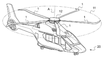
図1および2はブレード1を示し、ブレード1は、第一に、ブレード基端2とブレード先端9との間にブレード軸Bに沿って翼長にわたり延在し、第二に、前縁6と後縁7との間にブレード軸Bに対して垂直な横軸Tに沿って延在する。ブレード1は、ブレード基端2とブレード先端9との間に配置された翼型部分4を有する。翼型部分4は、ブレード軸Bに対して実質的に垂直な横断面内に配置された一連の翼型プロファイル15から構成され、各プロファイルはブレード1の一区切りを画定する。ブレード1はまた、ブレード1の自由端部に、すなわちブレード先端9の近くに二面体5を有する。
1 and 2 show a
ブレード1は、図3に示されるような回転翼航空機20のロータ11を形成する。ロータ11はハブ12と、ハブ12の回転軸Aの周りを回転する5個のブレード1とを含む。各ブレード1はブレード基端2でハブ12に接続される。
The
ロータ11はロータ半径Rによって、すなわち回転軸Aとブレード先端9との間のブレード軸Bに沿った距離によって特徴づけられる。ブレード1の各区切りのプロファイル15の弦cは、ブレード軸Bに対して実質的に垂直な横断面におけるブレード1の前縁6と後縁7との間の最大距離に一致する。平均弦
![]()
は翼型4にわたる弦cの平均値として定義される。ブレード基端2は、回転軸Aに基づいて0.1Rに等しい6番目の距離の所に配置され、ブレード1の翼型4の基端3は回転軸Aに基づいて0.2Rに等しい7番目の距離の所に配置される。
The
![]()
Is defined as the average value of the chord c over the
本発明のブレード1は、そのスイープ、弦およびねじれにおける変化についての関係性の組合せを提供し、それにより、第一に、接近飛行の間にロータ11の各ブレード1によって発せられる騒音を低減し、第二に、航空機20のホバリング飛行の間および前進飛行の間の両方で各ブレード1の空気力学性能を改善するようにする。
The
ブレード1はまた、もっぱらその弦およびねじれにおける変化についての関係性の組合せを提供し得、それにより航空機20のホバリング飛行の間および前進飛行の間の両方でロータ11の空気力学性能を改善するようにするが、各ブレード1の音響挙動は考慮されない。
ブレード1はまた、そのスイープおよび弦における変化についての関係性の組合せを提供し得、それにより、第一に、接近飛行の間にロータ11の各ブレード1によって発せられる騒音を低減し、第二に、航空機20の前進飛行における各ブレード1の空気力学性能を改善するようにする。各ブレード1の空気力学的性能は、主として航空機20の前進飛行のために、そのようにして最適化される。
The
ブレード1の各区切りのプロファイル15の弦、スイープおよびねじれにおける変化についての関係性が、それぞれ図4〜6にプロットされている。図7はブレード1のねじれの勾配を、すなわちロータ半径Rのロータ11のブレード1の翼長に沿ったねじれの局所的偏差を示している。
The relationships for changes in string, sweep and twist of each
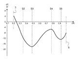
図4に示されるブレード1の各区切りのプロファイル15の弦における変化についての関係性は、横軸に沿ってプロットされた、ブレード1の翼長に沿ったブレード1の各区切りのプロファイル15の位置の、ロータ半径Rに対する比率と、縦軸に沿った、ブレード1の各区切りのプロファイル15の弦cの、平均弦
![]()
に対する比率とを含む。
The relationship for the change in the chord of
![]()
To the ratio.
平均弦
![]()
は、以下の式:
を適用してブレード1の各区切りのプロファイル15に半径の二乗r2によって重み付けして決定され、
上記式中、L(r)は回転軸Aに基づいて半径rに配置されたブレード1のプロファイルの局所的な弦の長さであり、R0は翼型4の基端3の半径であり、Rはブレード先端9の半径である。
Average string
![]()
Is the following formula:
Is applied to each
Where L (r) is the local chord length of the profile of the
弦の変化についてのこの関係性において、ブレード1の各区切りのプロファイル15の弦cは、翼型4の基端3と、0.85Rに等しい回転軸Aを起点にして第1の距離の所に配置された第1の区切りS1との間で増大する。第1の区切りS1を越えると、弦はブレード先端9まで低減する。弦cはブレード1の翼型部分の基端と、0.6Rに等しい回転軸Aを起点にして第8の距離の所に配置された第6の区切りS6との間で平均弦
![]()
未満であることを見ることができる。さらに、弦cは翼型部分4の基端3と第1の区切りS1との間で
![]()
で変化し、これは平均弦
![]()
からの±20%の変化を示す。ブレード基端の弦は
![]()
に等しい。
In this relationship with respect to string changes, the string c of each
![]()
You can see that it is less than. Further, the string c is between the
![]()
This is the average string
![]()
+/- 20% change from The string at the base of the blade
![]()
be equivalent to.
その後、ブレード1の各区切りのプロファイル15の弦は、第6の区切りS6と、0.85R〜0.95Rの範囲内に横たわる回転軸Aを起点にして第9の距離の所に配置された第7の区切りS7との間で平均弦
![]()
を上回る。最後に、ブレード1の各区切りのプロファイル15の弦は、第7の区切りS7を過ぎてブレード先端9まで平均弦
![]()
を下回る。
After that, the chords of the
![]()
It exceeds. Finally, the strings of the
![]()
Below.
加えて、弦cは、0.95Rに等しい10番目の距離の所に配置された第8の区切りS8を越えると実質的に放物線状の湾曲を辿りつつ低減する。そのようにしてブレード1の端部は放物線状の先端キャップ8を形成する。
In addition, the chord c decreases while following a substantially parabolic curve beyond the eighth segment S8 located at the tenth distance equal to 0.95R. In this way, the end of the
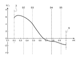
図6に示されるブレード1のねじれについての関係性は、多項式湾曲に対応する非線形の関係である。翼長に沿ったブレード1の区切りの各プロファイル15の位置の、ロータ半径Rに対する比率が、横軸に沿ってプロットされ、ブレード1の各区切りのプロファイル15のねじれ角θが縦軸に沿ってプロットされている。
The relationship regarding the twist of the
ねじれの勾配が図7に示され、それは横軸に沿って、ブレード1の翼長に沿ったブレード1の各区切りのプロファイル15の位置の、ロータ半径Rに対する比率を含み、縦軸に沿って、プロファイル15のねじれの局所的偏差を含む。
The twist gradient is shown in FIG. 7, which includes the ratio of the position of each
最初に、ねじれ角θは、翼型部分4の基端3と、0.35Rに等しい回転軸Aを起点にして第2の距離の所に配置された第2の区切りS2との間でほとんど変化しない。ねじれ角θの変化は翼型部分4の基端3と第2の区切りS2との間で2°未満である。翼長に沿ってねじれ角θはわずかに増大し、その後低減するが、このときねじれ勾配は翼型部分4の基端3の近くで正であり、第2の区切りS2の近くで低減して負になる。
Initially, the torsion angle θ is almost between the
その後、ねじれ角θは、第2の区切りS2と、0.48Rに等しい回転軸Aを起点にして第3の距離の所に配置された第3の区切りS3との間で低減し、ねじれ勾配は、第3の区切りS3の近くで−18°/Rに等しい第1の安定状態まで低減する。 Thereafter, the torsion angle θ decreases between the second segment S2 and the third segment S3 located at the third distance starting from the rotation axis A equal to 0.48R, and the torsion gradient Reduces to a first stable state equal to −18 ° / R near the third break S3.
その後、ねじれ角θは、第3の区切りS3と、0.78Rに等しい回転軸Aを起点にして第4の距離の所に配置された第4の区切りS4との間でさらに低減し、ねじれ勾配は、第4の区切りS4の近くで−6°/Rに等しい第2の安定状態まで上昇する。具体的には、ねじれ角θは、0.7Rに等しい回転軸Aを起点にしてある距離の所に配置されたブレード1のプロファイル15では0°に等しい。
Thereafter, the torsion angle θ is further reduced between the third segment S3 and the fourth segment S4 arranged at the fourth distance starting from the rotation axis A equal to 0.78R. The gradient rises to a second steady state equal to −6 ° / R near the fourth break S4. Specifically, the twist angle θ is equal to 0 ° in the
ねじれ角θは再び、第4の区切りS4と、0.92Rに等しい回転軸Aを起点にして第5の距離の所に配置された第5の区切りS5との間でさらに低減し、ねじれ勾配は、第5の区切りS5の近くで−13°/Rに等しい第3の安定状態まで低減する。 Again, the torsion angle θ is further reduced between the fourth segment S4 and the fifth segment S5 located at the fifth distance with the axis of rotation A equal to 0.92R as the torsional gradient. Decreases to a third stable state equal to −13 ° / R near the fifth break S5.
最後に、ねじれ角θは第5の区切りS5と、ブレード先端9との間で低減し、ねじれ勾配は、ブレード先端9において−8°/Rに等しいねじれ勾配まで上昇する。
Finally, the torsion angle θ decreases between the fifth segment S5 and the
ブレード1の区切りのプロファイル15の弦の変化についての関係性と組み合されたこのねじれの関係性は、ホバリング飛行の間および前進飛行の間の両方において、ブレード1の空気力学性能を改善する働きをする。
This torsional relationship combined with the relationship to the string change of
図5に示されるブレード1のスイープにおける変化についての関係性は、3つのスイープを画定する。ブレード軸Bに沿ったブレード1の各区切りのプロファイル15の位置の、ロータ半径Rに対する比率が、横軸に沿ってプロットされ、これらのプロファイル15のそれぞれのスイープ角度αが縦軸に沿ってプロットされている。
The relationship for changes in the sweep of the
従ってスイープは最初に、翼型部分4の基端3と、0.67Rに等しい回転軸Aを起点にして第11の距離の所に配置された第9の区切りS9との間でブレード1の前方に向かって方向付けられ、前縁6はブレード軸Bに対して4°に等しい前方第1スイープ角度α1を形成する。その後、スイープは、第9の区切りS9と、0.85Rに等しい回転軸Aを起点にして第12の距離の所に配置された第10の区切りS10との間でブレード1の前方に向かって方向付けられ、前縁6はブレード軸Bに対して8°に等しい前方第2スイープ角度α2を形成する。最後に、スイープは、第10の区切りS10と、ブレード先端9との間でブレード1の後方に向かって方向付けられ、前縁6はブレード軸Bに対して−23°に等しい後方第3スイープ角度α3を形成する。
Thus, the sweep initially begins with the
第1、第2および第3スイープ角度間の接続部分のそれぞれは好ましくは、これらの接続部分のいずれにも鋭角が無いように接続半径を考慮して形成される。これらの接続半径は例えば500ミリメートル(mm)のオーダーのものであり得る。 Each of the connecting portions between the first, second and third sweep angles is preferably formed taking into account the connecting radius so that none of these connecting portions has an acute angle. These connection radii can be, for example, on the order of 500 millimeters (mm).
さらに、ブレード1は、その自由端部に下方に向けられた二面体5を有する。この二面体5は第8の区切りS8の近くで端を発し、ブレード先端9で終端する。二面体5は主として、先行するするブレードによって生じる渦流の影響を低減することによってホバリング飛行の間ブレード1の空気力学的挙動を改善する働きをする。
Further, the
当然のことながら本発明はその実行に関して多数の変形が作製されてもよい。いくつかの実施形態を記載したが、全ての可能性のある実施形態を排他的に認識することは考えられないことは容易に理解されよう。本発明の範囲を逸脱することなく、記載された手段のいずれかを等価の手段で置き換えることを考えることは、当然のことながら可能である。 Of course, the present invention may be modified in many ways with respect to its implementation. Although several embodiments have been described, it will be readily appreciated that it is not possible to exclusively recognize all possible embodiments. It is, of course, possible to consider replacing any of the described means with equivalent means without departing from the scope of the invention.
Claims (18)
は前記翼型部分(4)にわたる前記弦cの平均値であり、前方第1方向が前記後縁(7)から前記前縁(6)まで定められ、後方第2方向が前記前縁(6)から前記後縁(7)まで定められ、
前記ブレード(1)は、その弦のおよびそのねじれの変化についての関係性の組合せを提供し、前記ねじれは前記ブレード(1)の前記翼型プロファイル(15)間の角度変化によって形成され、前記弦は前記翼型部分(4)の前記基端(3)と、0.6R〜0.9Rの範囲内にある前記回転軸(A)を起点にして第1の距離の所に配置された第1の区切りS1との間で増大し、前記弦は前記第1の区切りS1を越えると低減し、前記ねじれは、0.3R〜0.4Rの範囲内にある前記回転軸(A)を起点にして第2の距離の所に配置された第2の区切りS2と前記ブレード先端(9)との間で低減し、前記ねじれの第1の勾配は、前記第2の区切りS2と、0.4R〜0.6Rの範囲内にある前記回転軸(A)を起点にして第3の距離の所に配置された第3の区切りS3との間で−25°/R〜−4°/Rの範囲内にあり、前記ねじれの第2の勾配は、前記第3の区切りS3と、0.65R〜0.85Rの範囲内にある前記回転軸(A)を起点にして第4の距離の所に配置された第4の区切りS4との間で−25°/R〜−4°/Rの範囲内にあり、前記ねじれの第3の勾配は、前記第4の区切りS4と、0.85R〜0.95Rの範囲内にある前記回転軸(A)を起点にして第5の距離の所に配置された第5の区切りS5との間で−16°/R〜−4°/Rの範囲内にあり、前記ねじれの第4の勾配は、前記第5の区切りS5と前記ブレード先端(9)との間で−16°/R〜0°/Rの範囲内にあり、
その弦のおよびそのねじれの変化についての前記関係性は、そのスイープの変化についての関係性と組み合わせられ、前記スイープは、前記翼型部分(4)の前記基端(3)と、0.5R〜0.8Rの間にある前記回転軸(A)を起点にして第11の距離の所に配置された第9の区切りS9との間で前記ブレード(1)の前方に方向付けられる前記前縁と前記ブレード軸(B)との間の角度であり、前記前縁は、前記ブレード軸(B)に対して厳密に0°を超えかつ10°未満である前方第1スイープ角度α1を形成し、前記スイープは、前記第9の区切りS9と、0.6R〜0.95Rの範囲内にある前記回転軸(A)を起点にして第12の距離の所に配置された第10の区切りS10との間で前記ブレード(1)の前方に向けて方向付けられ、前記前縁は、前記ブレード軸(B)に対して1°〜15°の範囲内にある前方第2スイープ角度α2を形成し、前記スイープは、前記第10の区切りS10と、前記ブレード先端(9)との間で前記ブレード(1)の後方に向けて方向付けられ、前記前縁は、前記ブレード軸(B)に対して−35°〜−15°の範囲内にある後方第3スイープ角度α3を形成する、ブレード(1)。 A blade (1) for a rotor (11) of a rotary wing aircraft (20), said blade for rotating around a rotation axis (A), said blade (1) being A blade between a blade proximal end (2) suitable for being connected to the hub (12) of the rotor (11) and a blade tip (9) disposed at the free end of the blade (1) Extending along the axis (B) and secondly extending between the leading edge (6) and the trailing edge (7) along a transverse axis (T) perpendicular to the blade axis (B). The blade (1) includes an airfoil portion (4) disposed between the blade proximal end (2) and the blade tip (9), the airfoil portion (4) being a series of airfoils. Each airfoil profile (15) substantially with respect to the blade axis (B). Arranged in a straight cross section and delimiting the blade (1), the blade tip (9) being arranged at a distance equal to the rotor radius R starting from the axis of rotation (A), The maximum distance between the leading edge (6) and the trailing edge (7) in the plane constitutes the chord c of the airfoil profile (15) of each of the sections of the blade (1), and the average chord
Is the average value of the chord c over the airfoil portion (4), the first front direction is defined from the rear edge (7) to the front edge (6), and the second rear direction is the front edge (6 ) To the trailing edge (7),
The blade (1) provides a combination of relationships for changes in its chord and its twist, the twist being formed by an angular change between the airfoil profiles (15) of the blade (1), The string is arranged at a first distance from the base end (3) of the airfoil portion (4) and the rotation axis (A) within the range of 0.6R to 0.9R. The string increases with respect to the first segment S1, the string decreases when the first segment S1 is exceeded, and the twist causes the rotation axis (A) to fall within a range of 0.3R to 0.4R. The first gradient of twist is reduced between the second segment S2 and the second segment S2, arranged at a second distance from the starting point, and the blade tip (9). A third distance from the rotation axis (A) in the range of 4R to 0.6R. The second gradient of torsion is in the range of −25 ° / R to −4 ° / R between the third segment S3 and the third segment S3. A range of −25 ° / R to −4 ° / R from the rotation axis (A) in the range of 0.85R to the fourth segment S4 arranged at the fourth distance from the starting point And the third gradient of twist is at a fifth distance from the fourth segment S4 and the axis of rotation (A) in the range of 0.85R to 0.95R. The fourth gradient of torsion is in the range of −16 ° / R to −4 ° / R between the fifth segment S5 and the fifth segment S5, and the blade tip (9 ) In the range of −16 ° / R to 0 ° / R,
The relationship for the change in the string and the twist is combined with the relationship for the change in the sweep, the sweep being in the 0.5R with the proximal end (3) of the airfoil portion (4). The front directed to the front of the blade (1) with a ninth segment S9 located at an eleventh distance starting from the axis of rotation (A) between .about.0.8R. An angle between the edge and the blade axis (B), the leading edge having a forward first sweep angle α 1 that is strictly greater than 0 ° and less than 10 ° with respect to the blade axis (B). And the sweep is arranged at a twelfth distance starting from the ninth segment S9 and the rotation axis (A) in the range of 0.6R to 0.95R. Oriented toward the front of the blade (1) with the separator S10 Is the leading edge, the second forming a sweep angle alpha 2 forward with the blade axis relative to (B) in the range of 1 ° to 15 °, the sweep, the separated S10 in the first 10, the Oriented toward the rear of the blade (1) with respect to the blade tip (9), the leading edge being in the range of -35 ° to -15 ° with respect to the blade axis (B) forming a third sweep angle alpha 3, the blade (1).
の範囲内にある、請求項1に記載のブレード(1)。 The blade proximal end (2) is disposed at a sixth distance within the range of 0.05R to 0.3R starting from the rotation axis (A), and the proximal end of the airfoil portion (4) (3) is arranged at a seventh distance within a range of 0.1R to 0.4R starting from the rotation axis (A), and the seventh distance is equal to or greater than the sixth distance. A string near the proximal end (3) of the airfoil portion (4) of the blade (1)
The blade (1) according to claim 1, which is in the range of
から±40%だけ変化する、請求項1に記載のブレード(1)。 The average string between the base end (3) of the airfoil portion (4) and the first segment S1
The blade (1) according to claim 1, wherein the blade (1) varies by ± 40%.
が、以下の式:
を適用して前記ブレード(1)の前記区切りのそれぞれの前記プロファイル(15)に半径の二乗r2によって重み付けをして定義され、
上記式中、L(r)は、前記ブレード(1)のプロファイル(15)の局所的な弦の長さであり、前記局所的なプロファイル(15)は前記回転軸Aを起点にして半径rに配置され、R0は前記翼型部分(4)の前記基端(3)の半径であり、Rは前記ブレード先端(9)の半径である、請求項1に記載のブレード(1)。 The average string
But the following formula:
Defined by weighting each profile (15) of each of the breaks of the blade (1) by a square of the radius r 2 ,
In the above formula, L (r) is the local chord length of the profile (15) of the blade (1), and the local profile (15) has a radius r starting from the rotation axis A. The blade (1) according to claim 1, wherein R 0 is a radius of the proximal end (3) of the airfoil portion (4) and R is a radius of the blade tip (9).
Applications Claiming Priority (2)
| Application Number | Priority Date | Filing Date | Title |
|---|---|---|---|
| FR1502660A FR3045564B1 (en) | 2015-12-21 | 2015-12-21 | AIRCRAFT ROTOR BLADE WITH GEOMETRY ADAPTED FOR ACOUSTIC IMPROVEMENT DURING APPROACH FLIGHTS AND PERFORMANCE IMPROVEMENT IN STATIONARY AND ADVANCED FLIGHTS |
| FR1502660 | 2015-12-21 |
Publications (2)
| Publication Number | Publication Date |
|---|---|
| JP2017141013A true JP2017141013A (en) | 2017-08-17 |
| JP6336018B2 JP6336018B2 (en) | 2018-06-06 |
Family
ID=55542723
Family Applications (1)
| Application Number | Title | Priority Date | Filing Date |
|---|---|---|---|
| JP2016238613A Active JP6336018B2 (en) | 2015-12-21 | 2016-12-08 | Shaped aircraft rotor blades adapted for improved acoustics during close flight and to improve performance during hovering and forward flight |
Country Status (8)
| Country | Link |
|---|---|
| US (1) | US10220943B2 (en) |
| EP (1) | EP3184427B1 (en) |
| JP (1) | JP6336018B2 (en) |
| KR (1) | KR101898553B1 (en) |
| CN (1) | CN106892105B (en) |
| CA (1) | CA2951073C (en) |
| FR (1) | FR3045564B1 (en) |
| PL (1) | PL3184427T3 (en) |
Families Citing this family (11)
| Publication number | Priority date | Publication date | Assignee | Title |
|---|---|---|---|---|
| FR3075757B1 (en) * | 2017-12-22 | 2019-11-15 | Airbus Helicopters | AERODYNAMIC WRAPPED AERODYNAMIC ENVELOPES FOR BLADE COLLARS AND BLADE SLEEPING OF A ROTOR OF AN AIRCRAFT |
| CN207917132U (en) * | 2018-01-31 | 2018-09-28 | 深圳市大疆创新科技有限公司 | Propeller, Power Component and aircraft |
| FR3080606B1 (en) | 2018-04-26 | 2020-07-10 | Airbus Helicopters | DISTINCT PALE AIRCRAFT ROTOR WITH REDUCED NOISE Noise |
| WO2019241725A1 (en) * | 2018-06-15 | 2019-12-19 | The Texas A&M University System | Hover-capable aircraft |
| CN109533314B (en) * | 2018-11-14 | 2021-02-26 | 中国直升机设计研究所 | Pneumatic appearance of light unmanned helicopter rotor blade |
| RU2734154C1 (en) * | 2019-12-24 | 2020-10-13 | Общество с ограниченной ответственностью "ОКБ АВИАРЕШЕНИЯ" (ООО "ОКБ АВИАРЕШЕНИЯ") | Helicopter type aircraft propeller blade (embodiments) |
| CN112173075B (en) * | 2020-09-25 | 2022-12-30 | 中国直升机设计研究所 | Aerodynamic profile of helicopter low-noise rotor blade |
| CN112173077A (en) * | 2020-09-25 | 2021-01-05 | 中国直升机设计研究所 | Big front-back sweeping combined helicopter rotor blade |
| CN112977816B (en) * | 2021-05-17 | 2021-08-06 | 北京三快在线科技有限公司 | Rotor craft's paddle and rotor craft |
| CN114506443B (en) * | 2022-02-23 | 2023-06-23 | 北京航空航天大学 | Blade with guide structure, rotor, and blade design method |
| DE102023108565B3 (en) | 2023-04-04 | 2024-02-01 | P3X GmbH & Co. KG | Aircraft propeller and aircraft |
Citations (8)
| Publication number | Priority date | Publication date | Assignee | Title |
|---|---|---|---|---|
| JPS61181798A (en) * | 1985-02-07 | 1986-08-14 | ユナイテツド・テクノロジ−ズ・コ−ポレイシヨン | Prop fan |
| US5209643A (en) * | 1991-03-27 | 1993-05-11 | The Cessna Aircraft Company | Tapered propeller blade design |
| EP0592764A1 (en) * | 1992-10-16 | 1994-04-20 | Aviatika Joint-Stock Company | The propeller |
| JPH11139397A (en) * | 1997-09-10 | 1999-05-25 | Office Natl Etud Rech Aerospat (Onera) | Blade for aircraft rotor |
| US6364615B1 (en) * | 1999-05-21 | 2002-04-02 | Eurocopter | Blade for the rotary wings of an aircraft |
| US20090169381A1 (en) * | 2007-12-20 | 2009-07-02 | Eurocopter Deutschland Gmbh | Rotor blade for a rotor airplane |
| US20120251326A1 (en) * | 2011-03-31 | 2012-10-04 | Eurocopter Deutschland Gmbh | Noise and performance improved rotor blade for a helicopter |
| US20150050137A1 (en) * | 2010-12-15 | 2015-02-19 | Airbus Helicopters | Blade for a helicopter anti-torque device |
Family Cites Families (16)
| Publication number | Priority date | Publication date | Assignee | Title |
|---|---|---|---|---|
| US4248572A (en) * | 1978-12-11 | 1981-02-03 | United Technologies Corporation | Helicopter blade |
| US4439733A (en) | 1980-08-29 | 1984-03-27 | Technicare Corporation | Distributed phase RF coil |
| FR2689852B1 (en) | 1992-04-09 | 1994-06-17 | Eurocopter France | BLADE FOR AIRCRAFT TURNING WING, AT THE ARROW END. |
| FR2755941B1 (en) | 1996-11-19 | 1999-01-15 | Eurocopter France | ARROW BLADE AT ARROW FOR AIRCRAFT TURNING WING |
| JP2000118499A (en) | 1998-10-09 | 2000-04-25 | Commuter Helicopter Senshin Gijutsu Kenkyusho:Kk | Rotor blade for rotary wing plane |
| JP3189251B2 (en) | 1999-03-12 | 2001-07-16 | 株式会社コミュータヘリコプタ先進技術研究所 | Rotor blades for rotary wing aircraft |
| US6497385B1 (en) * | 2000-11-08 | 2002-12-24 | Continuum Dynamics, Inc. | Rotor blade with optimized twist distribution |
| JP4676633B2 (en) | 2001-03-28 | 2011-04-27 | 富士重工業株式会社 | Rotor blade of rotorcraft |
| JP3644497B2 (en) | 2001-04-16 | 2005-04-27 | 防衛庁技術研究本部長 | Rotor blade of rotorcraft |
| FR2865189B1 (en) | 2004-01-21 | 2007-02-16 | Eurocopter France | ROTATING SAIL BLADE WITH DOUBLE ARROW AND CLEARLY LIMITS. |
| US7600976B2 (en) * | 2005-05-31 | 2009-10-13 | Sikorsky Aircraft Corporation | Rotor blade twist distribution for a high speed rotary-wing aircraft |
| US7252479B2 (en) | 2005-05-31 | 2007-08-07 | Sikorsky Aircraft Corporation | Rotor blade for a high speed rotary-wing aircraft |
| US8128376B2 (en) * | 2005-08-15 | 2012-03-06 | Abe Karem | High performance outboard section for rotor blades |
| GB2486021B (en) | 2010-12-02 | 2017-07-19 | Agustawestland Ltd | Aerofoil |
| CN203078757U (en) | 2013-01-11 | 2013-07-24 | 何东飚 | Main rotary wing of single ultra-light helicopter |
| CN104149967B (en) | 2014-08-07 | 2015-05-06 | 西北工业大学 | Low-Reynolds-number airfoil profile with cooperative fluidic control, and control method thereof |
-
2015
- 2015-12-21 FR FR1502660A patent/FR3045564B1/en active Active
-
2016
- 2016-12-06 PL PL16202349T patent/PL3184427T3/en unknown
- 2016-12-06 EP EP16202349.3A patent/EP3184427B1/en active Active
- 2016-12-06 US US15/370,426 patent/US10220943B2/en not_active Expired - Fee Related
- 2016-12-07 CA CA2951073A patent/CA2951073C/en active Active
- 2016-12-08 JP JP2016238613A patent/JP6336018B2/en active Active
- 2016-12-12 KR KR1020160168854A patent/KR101898553B1/en active IP Right Grant
- 2016-12-19 CN CN201611178482.5A patent/CN106892105B/en active Active
Patent Citations (8)
| Publication number | Priority date | Publication date | Assignee | Title |
|---|---|---|---|---|
| JPS61181798A (en) * | 1985-02-07 | 1986-08-14 | ユナイテツド・テクノロジ−ズ・コ−ポレイシヨン | Prop fan |
| US5209643A (en) * | 1991-03-27 | 1993-05-11 | The Cessna Aircraft Company | Tapered propeller blade design |
| EP0592764A1 (en) * | 1992-10-16 | 1994-04-20 | Aviatika Joint-Stock Company | The propeller |
| JPH11139397A (en) * | 1997-09-10 | 1999-05-25 | Office Natl Etud Rech Aerospat (Onera) | Blade for aircraft rotor |
| US6364615B1 (en) * | 1999-05-21 | 2002-04-02 | Eurocopter | Blade for the rotary wings of an aircraft |
| US20090169381A1 (en) * | 2007-12-20 | 2009-07-02 | Eurocopter Deutschland Gmbh | Rotor blade for a rotor airplane |
| US20150050137A1 (en) * | 2010-12-15 | 2015-02-19 | Airbus Helicopters | Blade for a helicopter anti-torque device |
| US20120251326A1 (en) * | 2011-03-31 | 2012-10-04 | Eurocopter Deutschland Gmbh | Noise and performance improved rotor blade for a helicopter |
Also Published As
| Publication number | Publication date |
|---|---|
| KR101898553B1 (en) | 2018-09-13 |
| EP3184427A1 (en) | 2017-06-28 |
| PL3184427T3 (en) | 2019-02-28 |
| EP3184427B1 (en) | 2018-08-29 |
| CA2951073A1 (en) | 2017-02-07 |
| FR3045564B1 (en) | 2018-08-17 |
| CA2951073C (en) | 2019-07-02 |
| US10220943B2 (en) | 2019-03-05 |
| JP6336018B2 (en) | 2018-06-06 |
| FR3045564A1 (en) | 2017-06-23 |
| CN106892105B (en) | 2019-12-13 |
| CN106892105A (en) | 2017-06-27 |
| US20170174340A1 (en) | 2017-06-22 |
| KR20170074175A (en) | 2017-06-29 |
Similar Documents
| Publication | Publication Date | Title |
|---|---|---|
| JP6336018B2 (en) | Shaped aircraft rotor blades adapted for improved acoustics during close flight and to improve performance during hovering and forward flight | |
| JP6377709B2 (en) | Shaped aircraft rotor blades adapted for acoustic improvement during close flight and to improve performance during forward flight | |
| US9061758B2 (en) | Noise and performance improved rotor blade for a helicopter | |
| JP3916723B2 (en) | Rotor blade of rotorcraft | |
| JP4551778B2 (en) | Forward and backward rotor blades with limited taper ratio | |
| US6116857A (en) | Blade with reduced sound signature, for aircraft rotating aerofoil, and rotating aerofoil comprising such a blade | |
| US20070187549A1 (en) | Airfoil for a helicoptor rotor blade | |
| US11225316B2 (en) | Method of improving a blade so as to increase its negative stall angle of attack | |
| JP2000264295A (en) | Rotor blade of rotary wing aircraft | |
| JP6053825B2 (en) | Wind turbine blades with geometric sweep | |
| US11148794B2 (en) | Method of determining an initial leading edge circle of airfoils of a blade and of improving the blade in order to increase its negative stall angle of attack | |
| US11338913B2 (en) | Autogyro rotor blade for generating lift by autorotation | |
| JP2000118499A (en) | Rotor blade for rotary wing plane | |
| JP4086374B6 (en) | Aircraft blade |
Legal Events
| Date | Code | Title | Description |
|---|---|---|---|
| A131 | Notification of reasons for refusal |
Free format text: JAPANESE INTERMEDIATE CODE: A131 Effective date: 20171128 |
|
| A521 | Request for written amendment filed |
Free format text: JAPANESE INTERMEDIATE CODE: A523 Effective date: 20171225 |
|
| TRDD | Decision of grant or rejection written | ||
| A01 | Written decision to grant a patent or to grant a registration (utility model) |
Free format text: JAPANESE INTERMEDIATE CODE: A01 Effective date: 20180417 |
|
| A61 | First payment of annual fees (during grant procedure) |
Free format text: JAPANESE INTERMEDIATE CODE: A61 Effective date: 20180501 |
|
| R150 | Certificate of patent or registration of utility model |
Ref document number: 6336018 Country of ref document: JP Free format text: JAPANESE INTERMEDIATE CODE: R150 |
|
| R250 | Receipt of annual fees |
Free format text: JAPANESE INTERMEDIATE CODE: R250 |
|
| R250 | Receipt of annual fees |
Free format text: JAPANESE INTERMEDIATE CODE: R250 |
|
| R250 | Receipt of annual fees |
Free format text: JAPANESE INTERMEDIATE CODE: R250 |