JP2017140716A - Multiple writing implement - Google Patents

Multiple writing implement Download PDF

Info

Publication number
JP2017140716A
JP2017140716A JP2016022159A JP2016022159A JP2017140716A JP 2017140716 A JP2017140716 A JP 2017140716A JP 2016022159 A JP2016022159 A JP 2016022159A JP 2016022159 A JP2016022159 A JP 2016022159A JP 2017140716 A JP2017140716 A JP 2017140716A
Authority
JP
Japan
Prior art keywords
coil spring
writing
core
coil
core member
Prior art date
Legal status (The legal status is an assumption and is not a legal conclusion. Google has not performed a legal analysis and makes no representation as to the accuracy of the status listed.)
Granted
Application number
JP2016022159A
Other languages
Japanese (ja)
Other versions
JP6713293B2 (en
Inventor
安永 雅博
Masahiro Yasunaga
雅博 安永
Current Assignee (The listed assignees may be inaccurate. Google has not performed a legal analysis and makes no representation or warranty as to the accuracy of the list.)
Sakura Color Products Corp
Original Assignee
Sakura Color Products Corp
Priority date (The priority date is an assumption and is not a legal conclusion. Google has not performed a legal analysis and makes no representation as to the accuracy of the date listed.)
Filing date
Publication date
Application filed by Sakura Color Products Corp filed Critical Sakura Color Products Corp
Priority to JP2016022159A priority Critical patent/JP6713293B2/en
Publication of JP2017140716A publication Critical patent/JP2017140716A/en
Application granted granted Critical
Publication of JP6713293B2 publication Critical patent/JP6713293B2/en
Active legal-status Critical Current
Anticipated expiration legal-status Critical

Links

Images

Abstract

PROBLEM TO BE SOLVED: To provide a multiple writing implement having a mixed group of writing cores with different diameters, which can avoid providing different operational feelings depending on the writing core and has less discomfort in use.SOLUTION: A multiple writing implement comprises: a barrel 2 having a projection port 9 at its tip; a plurality of writing cores 3a, 3b having writing parts 20, 31; a plurality of coil springs 7, 8; and a plurality of operational means 5, 45. The plurality of writing cores 3a, 3b are arranged in the barrel 2 with the coil springs 7, 8 attached to outer peripheral parts of writing cores 20, 31. The plurality of writing cores 3a, 3b are energized toward an inner direction of the barrel 2 by the coil springs 7, 8. Thereby, an operation of operational means 5, 45 can selectively project the writing cores 3a, 3b from the projection port 9 in the multiple writing implement 1, in which the coil springs 7, 8 have respective spring constants substantially equal to each other and have different bore diameters. Some writing cores in a group of the writing cores 3a, 3b have different diameters from other ones. The writing core 3b having a small diameter is provided with a coil springs 8 having a small bore diameter.SELECTED DRAWING: Figure 4

Description

本発明は、複数の筆記芯が軸筒の内外に出退する機構を備えた複式筆記具に関するものである。   The present invention relates to a compound writing instrument provided with a mechanism in which a plurality of writing cores move in and out of a shaft cylinder.

軸筒内にボールペンレフィルや、シャープペンシルユニットを含む複数の筆記芯が内蔵された複式筆記具が知られている。複式筆記具では、軸筒の側面や後端から操作片等の操作部材が突出しており、使用者は操作片等を操作して各筆記芯を前後に移動させることができる。複式筆記具は、使用者が操作片等を操作して各筆記芯の先端部分を軸筒の先端開口から選択的に出没させて使用される。   2. Description of the Related Art There is known a compound writing instrument in which a plurality of writing cores including a ball pen refill and a mechanical pencil unit are built in a shaft cylinder. In the compound writing instrument, an operation member such as an operation piece protrudes from the side surface or the rear end of the shaft tube, and the user can operate the operation piece or the like to move each writing core back and forth. The compound writing instrument is used by a user operating an operation piece or the like so that the tip portion of each writing core is selectively projected and retracted from the tip opening of the shaft tube.

このような筆記具として、例えば、特許文献1に開示された複式筆記具がある。特許文献1に開示されている複式筆記具では、各筆記軸(筆記芯)が各々コイルばねの付勢力で後方に付勢されて軸筒内に収納されており、操作片等の操作部材を操作し、コイルばねの付勢力に抗して選択した一つの筆記軸を前方へ移動させると、当該筆記軸の先端部が軸筒の先端開口から突出する。そして、固定手段によって軸筒に対する当該筆記軸の位置が固定され、先端部が突出した状態を維持し、筆記可能な状態となる。   As such a writing instrument, for example, there is a double-type writing instrument disclosed in Patent Document 1. In the dual-type writing instrument disclosed in Patent Document 1, each writing shaft (writing core) is urged rearward by the urging force of the coil spring and is housed in the shaft cylinder, and the operation member such as an operation piece is operated. When one writing shaft selected against the urging force of the coil spring is moved forward, the tip of the writing shaft projects from the tip opening of the shaft tube. And the position of the said writing shaft with respect to a shaft cylinder is fixed by the fixing means, the state which the front-end | tip part protruded will be maintained, and it will be in a writable state.

前記した様に複式筆記具は、複数の筆記芯を有し、操作片等を手動操作して一つの筆記芯を選択的に突出させて使用する。
複式筆記具は、突出させる筆記芯が違っていても、操作片等の操作感が同じであることが望ましい。例えば、赤色ボールペンレフィル、青色ボールペンレフィル、黒色ボールペンレフィル、シャープペンシルユニットの4種の筆記芯を有する場合、操作片等を操作していずれの筆記芯を突出させる場合でも同一の使用感で突出させることができることが望ましい。
そのため従来の複式筆記具では、各筆記芯を後方へ付勢するコイルばねとして、すべて同一規格のばねが使用されていた。即ち従来技術の複式筆記具では、複数の筆記芯を有し、それぞれの筆記芯にコイルばねが装着されているが、全てのコイルばねは同一規格であり、その自然長(全長)、外径、内径、線径、巻数、ばね定数は全て同じであった。
As described above, the compound writing instrument has a plurality of writing cores, and is used by manually operating an operation piece or the like to selectively project one writing core.
It is desirable that the dual writing instrument has the same operational feeling as the operation piece even if the writing core to be projected is different. For example, if you have four types of writing cores, red ballpoint pen refill, blue ballpoint pen refill, black ballpoint pen refill, and mechanical pencil unit, even if you operate the operation piece etc. It is desirable to be able to.
For this reason, in the conventional double-type writing instrument, springs of the same standard are used as coil springs for urging each writing core backward. That is, in the prior art compound writing instrument, it has a plurality of writing cores, and coil springs are attached to each writing core, but all the coil springs are of the same standard, their natural length (full length), outer diameter, The inner diameter, wire diameter, number of turns, and spring constant were all the same.

特開2011−240555号公報JP2011-240555A

前記した様に複式筆記具は、複数の筆記芯を内蔵しているが、筆記芯の太さは一様であるとは限らない。例えば、ボールペンレフィルとシャープペンシルユニットが混在している場合、ボールペンレフィルの太さとシャープペンシルユニットの太さが違う場合がある。またボールペンレフィル同士であっても色によってその太さが違う場合がある。   As described above, the dual-type writing instrument incorporates a plurality of writing cores, but the thickness of the writing core is not always uniform. For example, when a ballpoint pen refill and a mechanical pencil unit are mixed, the thickness of the ballpoint pen refill may be different from the thickness of the mechanical pencil unit. Even the ballpoint pen refills may have different thicknesses depending on the color.

従来技術においては、筆記芯の太さが違っていても、操作感に差異が生じない様に、同一規格のコイルばねが装着されていた。そのため筆記芯の外周面とコイルばねの内周のクリアランスが筆記芯によって違うものとなり、筆記芯によって操作片の操作感が違ってしまう場合があった。すなわち、クリアランスが大きいと、圧縮されたコイルばねが蛇行状に変形したり、隣接するコイルばね同士が接触することにより、操作片の操作に違和感を覚えてしまう場合があった。   In the prior art, coil springs of the same standard are mounted so that there is no difference in operation feeling even if the thickness of the writing core is different. Therefore, the clearance between the outer peripheral surface of the writing core and the inner periphery of the coil spring differs depending on the writing core, and the operation feeling of the operation piece may be different depending on the writing core. That is, when the clearance is large, the compressed coil spring may be deformed in a meandering manner, or the adjacent coil springs may come into contact with each other, which may make the operation piece feel uncomfortable.

具体的には、以下の様である。
図12(a)は、複式筆記具の内部を示しており、隣接した二つの筆記芯63aを部分的に拡大して示したモデル図である。両方の筆記芯63aに、同規格のコイルばね68が装着されている。図12(a)において、下方がペン先であり、筆記芯63aをペン先側へ移動させると、コイルばね68が圧縮される。すなわち、筆記芯63aのペン先を図示しない先端開口から突出させる際には、使用者はコイルばね68の付勢力に抗して操作片65を操作する。
Specifically, it is as follows.
FIG. 12A shows the inside of the dual-type writing instrument, and is a model diagram showing a partially enlarged view of two adjacent writing cores 63a. Coil springs 68 of the same standard are attached to both writing cores 63a. In FIG. 12A, the lower side is the pen tip, and when the writing core 63a is moved to the pen tip side, the coil spring 68 is compressed. That is, when the pen tip of the writing core 63 a is protruded from a tip opening (not shown), the user operates the operation piece 65 against the urging force of the coil spring 68.

図12(a)に示す左方のコイルばね68が、図12(b)に示す様に圧縮された際に、コイルばね68が蛇行形状とならない様に、又は、蛇行形状が小さくなる様に、コイルばね68の内周から筆記芯63aの外周面までの距離(クリアランス)が設定されている。   When the left coil spring 68 shown in FIG. 12 (a) is compressed as shown in FIG. 12 (b), the coil spring 68 does not become a meandering shape or the meandering shape becomes small. A distance (clearance) from the inner periphery of the coil spring 68 to the outer peripheral surface of the writing core 63a is set.

また、筆記芯63aに装着されたコイルばね68が、隣接する別のコイルばね68に接触しない様に、隣接する筆記芯63a同士の間隔F(図12(a))が設定されている。間隔Fが設定された結果、コイルばね68同士の間隔は、S4となっている。
また、コイルばね68が圧縮されると、図12(b)に示す例では、圧縮されたコイルばね68と、当該コイルばね68と隣接する別のコイルばね68の最も接近した部位の間隔はS5となる。すなわち、コイルばね68が座屈しても、両コイルばね68同士の間隔は、少なくとも間隔S5(S5<S4)が確保されており、両コイルばね68は接触しない。
Further, an interval F (FIG. 12A) between adjacent writing cores 63 a is set so that the coil spring 68 attached to the writing core 63 a does not come into contact with another adjacent coil spring 68. As a result of the interval F being set, the interval between the coil springs 68 is S4.
When the coil spring 68 is compressed, in the example shown in FIG. 12B, the interval between the compressed coil spring 68 and the closest coil spring 68 adjacent to the coil spring 68 is S5. It becomes. That is, even if the coil spring 68 is buckled, at least the distance S5 (S5 <S4) is secured between the two coil springs 68, and the two coil springs 68 do not contact each other.

ところが、このコイルばね68を、図13(a)に示す様に、筆記芯63aよりも小径の筆記芯63bに装着すると、コイルばね68と筆記芯63bのクリアランスは大きくなる。その結果、筆記芯63bに装着されたコイルばね68は、圧縮されると図13(c)に示す様に、蛇行形状を呈し易くなる。
すなわち、図13(a)に示す様に、太さが比較的細い筆記芯63bが使用される場合には、当該筆記芯63bとコイルばね68の間のクリアランスが、筆記芯63aとコイルばね68のクリアランスよりも大きくなるため、筆記芯63bに装着されたコイルばね68が圧縮されると、当該コイルばね68は一方向のみならず、複数の方向に偏心したいわゆる蛇行形状を呈し易い。
その結果、使用者が操作片65を押圧する際に、手に掛かる荷重が不規則に変化してしまう懸念がある。
However, when the coil spring 68 is mounted on a writing core 63b having a smaller diameter than the writing core 63a as shown in FIG. 13A, the clearance between the coil spring 68 and the writing core 63b is increased. As a result, the coil spring 68 attached to the writing core 63b is likely to have a meandering shape as shown in FIG. 13C when compressed.
That is, as shown in FIG. 13 (a), when a writing core 63b having a relatively small thickness is used, the clearance between the writing core 63b and the coil spring 68 is such that the writing core 63a and the coil spring 68 have a clearance. Therefore, when the coil spring 68 attached to the writing core 63b is compressed, the coil spring 68 tends to exhibit a so-called meandering shape that is eccentric not only in one direction but also in a plurality of directions.
As a result, when the user presses the operation piece 65, there is a concern that the load applied to the hand changes irregularly.

また筆記芯63bとコイルばね68のクリアランスが大きいため、当該コイルばね68が圧縮されると、隣接する他のコイルばね68と接触する恐れがある。すなわち、クリアランスが大きいため、図13(b)に示す様に、筆記芯63bに装着されたコイルばね68が大きく座屈することがある。そのため、当該コイルばね68が、隣接する他のコイルばね68と接触することがある。
その結果、操作片65を操作する際に、引っ掛かり感が生じてしまう。
Further, since the clearance between the writing core 63b and the coil spring 68 is large, there is a possibility that when the coil spring 68 is compressed, it contacts with another adjacent coil spring 68. That is, since the clearance is large, the coil spring 68 attached to the writing core 63b may buckle greatly as shown in FIG. 13B. Therefore, the coil spring 68 may come into contact with another adjacent coil spring 68.
As a result, when the operation piece 65 is operated, a feeling of catching occurs.

この様に従来技術の複式筆記具は、操作片等の操作感が筆記芯によって異なる場合があり、使用者に違和感を与える場合があった。   As described above, in the conventional writing instrument, the operation feeling of the operation piece or the like may differ depending on the writing core, and the user may feel uncomfortable.

本発明は、従来技術の上記した問題点に注目し、太さが異なる筆記芯が混在する複式筆記具であって、操作感が筆記芯によって異ならず、使用時の違和感が少ない複式筆記具を提供することを課題とする。   The present invention focuses on the above-mentioned problems of the prior art, and provides a dual-type writing instrument in which writing cores having different thicknesses are mixed, and the operational feeling does not differ depending on the writing core, and there is little discomfort during use. This is the issue.

上記課題を解決するための請求項1に記載の発明は、先端が開口し内部に中空部分を有する軸筒と、先端に筆記部を有する複数の筆記芯と、複数のコイルばねと、複数の操作手段を有し、各筆記芯の外周部に前記コイルばねが装着された状態で前記複数の筆記芯が前記軸筒内に配されており、各筆記芯は前記コイルばねによって軸筒内部方向に向かって付勢されており、操作手段を操作することによって先端の開口から選択的に筆記芯を突出させる複式筆記具において、複数のコイルばねには、ばね定数が実質的に同一であって内径又は外径が異なるものがあり、前記筆記芯には太さが異なるものが混在し、太さの細い筆記芯には内径又は外径の少なくとも一方が小さいコイルばねが装着されていることを特徴とする複式筆記具である。   The invention according to claim 1 for solving the above-mentioned problem is a shaft cylinder having an open end and having a hollow portion therein, a plurality of writing cores having a writing portion at the tip, a plurality of coil springs, and a plurality of coil springs. The plurality of writing cores are arranged in the shaft cylinder in a state in which the coil springs are mounted on the outer peripheral portion of each writing core, and each writing core is arranged in the direction of the shaft cylinder by the coil spring. In the dual writing instrument in which the writing core is selectively protruded from the opening at the tip by operating the operating means, the plurality of coil springs have substantially the same spring constant and an inner diameter. Or, there are those having different outer diameters, the writing cores having different thicknesses are mixed, and the thin writing core is provided with a coil spring having a small inner diameter or outer diameter. This is a dual writing instrument.

ここで、「実質的に同一」とは、コイルばねの誤差を考慮して同一の範囲と言えるものであることを意味している。すなわち、コイルばねは、全く同一のものを製造することが困難であり、同一仕様,同一の製造方法,同一の製造過程で製造しても、ロットによってばね定数にある程度のばらつきが生じてしまう。そのため、例えば、JIS B 2704−2:2009の「第2部:圧縮コイルばねの仕様の表し方 6.2(c)ばね定数の許容差 表4」にはばね定数の許容値が規定されている。例えば、JIS B 2704−2:2009では、最大でプラスマイナス12%の誤差を許容している。
本発明において、「実質的に同一」の範囲は、前記したJIS規格に限定されるものではないが、これに準じる範囲のものは「実質的に同一」であると言える。
本発明の複式塗布具では、太さの細い筆記芯には内径又は外径の少なくとも一方が小さいコイルばねが装着されている。
そのため当該筆記芯を突出させるべく操作手段(操作片等)を操作し、コイルばねを圧縮する際、コイルばねは蛇行せずに真っ直ぐに縮む。そのため操作手段を操作する際に使用者に引っ掛かり感等を感じさせない。
また各筆記芯に装着されているコイルばねは、ばね定数が実質的に同一である。そのため本発明の複式塗布具では、いずれの筆記芯を突出させる際にも同じような操作感を感じさせることができる。
Here, “substantially the same” means that the same range can be said in consideration of the error of the coil spring. That is, it is difficult to manufacture exactly the same coil spring, and even if manufactured with the same specifications, the same manufacturing method, and the same manufacturing process, the spring constant will vary to some extent depending on the lot. Therefore, for example, JIS B 2704-2: 2009 “Part 2: How to express the specifications of compression coil springs 6.2 (c) Tolerance of spring constants Table 4” defines allowable values of spring constants. Yes. For example, JIS B 2704-2: 2009 allows an error of plus or minus 12% at the maximum.
In the present invention, the range of “substantially the same” is not limited to the above-mentioned JIS standard, but the range according to this is “substantially the same”.
In the duplex applicator of the present invention, a coil spring having a small inner diameter or outer diameter is attached to a thin writing core.
Therefore, when the operating means (operating piece or the like) is operated to project the writing core and the coil spring is compressed, the coil spring does not meander but contracts straight. Therefore, when operating the operating means, the user does not feel a catching feeling or the like.
In addition, the coil springs mounted on the writing cores have substantially the same spring constant. Therefore, in the double applicator of the present invention, the same operational feeling can be felt when any writing core is projected.

太さの細い筆記芯には内径が小さいコイルばねが装着されており、当該内径が小さいコイルばねの線径は、内径が大きいコイルばねの線径よりも太いことが望ましい(請求項2)。   A coil spring having a small inner diameter is attached to the writing core having a small thickness, and the coil diameter of the coil spring having a small inner diameter is preferably larger than the wire diameter of the coil spring having a large inner diameter.

太さの細い筆記芯には内径が小さいコイルばねが装着されており、内径が小さいコイルばねの座巻き部分を除いた有効巻数は、内径が大きいコイルばねの座巻き部分を除いた有効巻数よりも多いことが望ましい(請求項3)。   A coil spring with a small inner diameter is attached to a thin writing core, and the effective number of turns excluding the coiled part of the coil spring with a small inner diameter is larger than the effective number of turns excluding the coiled part of the coil spring with a large inner diameter. It is desirable that the amount be too large.

太さの細い筆記芯には内径が小さいコイルばねが装着されており、内径が小さいコイルばねは、端部に拡径部を有していることが望ましい(請求項4)。   A coil spring having a small inner diameter is attached to the writing core having a small thickness, and it is desirable that the coil spring having a small inner diameter has an enlarged portion at the end.

請求項5に記載の発明は、太さが細い方の筆記芯が、シャープペンシルユニットであり、太さが太い方の筆記芯が、ボールペンレフィルであることを特徴とする請求項1乃至4のいずれかに記載の複式筆記具である。   The invention according to claim 5 is characterized in that the writing core having a smaller thickness is a mechanical pencil unit, and the writing core having a larger thickness is a ball pen refill. The compound writing instrument according to any one of the above.

本発明によると、太さが相違する各筆記芯の収納位置から突出位置まで移動する際における、操作手段の操作に違和感がない。   According to the present invention, there is no sense of incongruity in the operation of the operating means when moving from the storage position of each writing core having a different thickness to the protruding position.

本発明の実施形態に係る複式筆記具の斜視図であり、いずれの筆記芯のペン先も軸筒の先端の突出口から突出していない状態を示す。It is a perspective view of the dual-type writing instrument which concerns on embodiment of this invention, and shows the state which the pen point of any writing core does not protrude from the protrusion opening of the front-end | tip of a shaft cylinder. 図1において、ボールペンレフィルのペン先が突出口から突出している状態を示す斜視図である。In FIG. 1, it is a perspective view which shows the state which the pen point of a ball-point pen refill has protruded from the protrusion port. 図1において、シャープペンシルユニットのペン先が突出口から突出している状態を示す斜視図である。In FIG. 1, it is a perspective view which shows the state which the pen point of a mechanical pencil unit protrudes from the protrusion port. 図1の複式筆記具の断面図である。It is sectional drawing of the double-type writing instrument of FIG. 1つのボールペンレフィルと、当該ボールペンレフィルに係合する複式筆記具の要部のみを描写した説明図であり、(a)はペン先が軸筒内に収納されている状態を示し、(b)はペン先が軸筒から突出している状態を示す。It is explanatory drawing which described only the principal part of one ball-point pen refill and the double-type writing instrument engaged with the said ball-point pen refill, (a) shows the state by which the pen point is accommodated in the axial cylinder, (b) The state where the pen tip protrudes from the shaft cylinder is shown. シャープペンシルユニットと、当該シャープペンシルユニットに係合する複式筆記具の要部のみを描写した説明図であり、(a)はペン先が軸筒内に収納されている状態を示し、(b)はペン先が軸筒から突出している状態を示す。It is explanatory drawing which portrayed only the principal part of a mechanical pencil unit and the compound writing instrument engaged with the said mechanical pencil unit, (a) shows the state by which the pen point is accommodated in the axial cylinder, (b) The state where the pen tip protrudes from the shaft cylinder is shown. 図1の複式筆記具のコイルばね部分を示す説明図であり、(a)は、シャープペンシルユニットに装着されているコイルばねと、ボールペンレフィルに装着されているコイルばねの、装着時の全長を示しており、(b)は、シャープペンシルユニットのペン先が、軸筒の先端の突出口から突出した際における、シャープペンシルユニットに装着されているコイルばねが座屈している状態を示している。It is explanatory drawing which shows the coil spring part of the compound writing instrument of FIG. 1, (a) shows the full length at the time of mounting | wearing of the coil spring with which the mechanical pencil unit is mounted | worn, and the coil spring with which the ball-point pen refill is mounted | worn. (B) shows a state where the coil spring attached to the mechanical pencil unit is buckled when the pen tip of the mechanical pencil unit protrudes from the protruding opening at the tip of the shaft cylinder. 図1の複式筆記具のコイルばね部分を示す説明図であり、(a)は、シャープペンシルユニットに装着されているコイルばねと、ボールペンレフィルに装着されているコイルばねの、装着時の全長を示しており、(b)は、ボールペンレフィルのペン先が、軸筒の先端の突出口から突出した際における、ボールペンレフィルに装着されているコイルばねが座屈している状態を示している。It is explanatory drawing which shows the coil spring part of the compound writing instrument of FIG. 1, (a) shows the full length at the time of mounting | wearing of the coil spring with which the mechanical pencil unit is mounted | worn, and the coil spring with which the ball-point pen refill is mounted | worn. (B) shows a state where the coil spring attached to the ballpoint pen refill is buckled when the penpoint of the ballpoint pen refill projects from the projecting opening at the tip of the shaft cylinder. 図4の補助部材のA−A方向から見た矢視図である。It is the arrow line view seen from the AA direction of the auxiliary member of FIG. ボールペンレフィル用のコイルばねの側面図である。It is a side view of the coil spring for ball-point pen refills. シャープペンシルユニット用のコイルばねの側面図である。It is a side view of the coil spring for mechanical pencil units. 従来の複式筆記具における筆記芯にコイルばねが装着された状態のモデル図であり、(a)は、両筆記芯が軸筒内に収納された筆記不能のときの各コイルばねの状態を示しており、(b)は、一方の筆記芯が軸筒から突出した際における、当該筆記芯に装着されているコイルばねが圧縮されて座屈している状態を示している。It is a model figure of the state by which the coil spring was mounted | worn with the writing core in the conventional compound writing instrument, (a) shows the state of each coil spring when both writing cores are stored in the shaft cylinder and writing is impossible. (B) shows a state in which the coil spring attached to the writing core is compressed and buckled when one of the writing cores protrudes from the shaft cylinder. 従来の複式筆記具における太さが相違する筆記芯に各々同じ規格のコイルばねが装着された状態のモデル図であり、(a)は、両筆記芯が軸筒内に収納された筆記不能なときの各コイルばねの状態を示しており、(b)は、一方の筆記芯が軸筒から突出した際における、当該筆記芯に装着されているコイルばねが圧縮されて座屈している状態を示しており、(c)は、一方の筆記芯が軸筒から突出した際における、当該筆記芯に装着されているコイルばねが圧縮されて蛇行形状を呈している状態を示している。It is a model figure of the state in which the coil spring of the same standard was each attached to the writing core in which thickness differs in the conventional compound writing instrument, (a) is when writing is impossible when both writing cores are stored in the shaft cylinder (B) shows a state in which the coil spring mounted on the writing core is compressed and buckled when one of the writing cores protrudes from the shaft cylinder. (C) shows a state in which the coil spring mounted on the writing core is compressed and has a meandering shape when one writing core protrudes from the shaft cylinder.

以下さらに、本発明の実施形態について説明する。なお、以下の説明において前後の関係はペン先側を前側、ペン軸側を後側として説明する。
本実施形態の複式筆記具は、複数の芯部材を内蔵し、これを選択的に突出させることができるものである。本実施形態の複式筆記具は、芯部材を軸筒内部方向(すなわち、後方側)に付勢するコイルばねに特徴がある。特徴部分の説明に先立って、複式筆記具の概要について説明し、その後で特徴部分たるコイルばねについて詳細に説明する。
Further embodiments of the present invention will be described below. In the following description, the front-rear relationship will be described with the pen tip side as the front side and the pen shaft side as the rear side.
The dual-type writing instrument of the present embodiment has a plurality of core members built therein and can selectively project them. The dual-type writing instrument of this embodiment is characterized by a coil spring that urges the core member in the axial direction (that is, the rear side). Prior to the description of the characteristic part, an outline of the compound writing instrument will be described, and then the coil spring as the characteristic part will be described in detail.

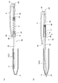
本実施形態の複式筆記具1は、図1〜図4で示されるように、本体である軸筒2と、軸筒2の内部に配される芯部材3a,3b(筆記芯)と、芯部材3a,3bを所定の位置で前後移動可能に保持するための補助部材4と、操作部材5,45と、芯部材3a,3bを後方へ付勢する2種類のボールペンレフィル用コイルばね7,シャープペンシルユニット用コイルばね8を備えている。   As shown in FIGS. 1 to 4, the compound writing instrument 1 of the present embodiment includes a shaft cylinder 2 that is a main body, core members 3 a and 3 b (writing cores) disposed inside the shaft cylinder 2, and a core member. Auxiliary member 4 for holding 3a and 3b movably back and forth at a predetermined position, operation members 5 and 45, two types of coil springs 7 for ball pen refill for urging the core members 3a and 3b backward, sharp A pencil unit coil spring 8 is provided.

軸筒2は、図1に示す様に、前側筒部12と、後側筒部13により構成されている。これら前側筒部12と、後側筒部13の内部には空間が形成されており、それぞれの空間は、前側筒部12と後側筒部13が一体に取り付けられたとき、連通した状態となる。   As shown in FIG. 1, the shaft cylinder 2 includes a front cylinder part 12 and a rear cylinder part 13. Spaces are formed in the front cylinder part 12 and the rear cylinder part 13, and the spaces communicate with each other when the front cylinder part 12 and the rear cylinder part 13 are integrally attached. Become.

前側筒部12は、前後端にそれぞれ開口を有する略円筒状の部材であり、前端近傍の部分が前端に向かうにつれて狭径となっている。前端部分に形成された開口は、芯部材3の前端部分(ペン先部分)を外部に突出させるための突出口9となる開口であり、内部に形成される空間と外部とを連通させている。   The front cylinder portion 12 is a substantially cylindrical member having openings at the front and rear ends, and the portion near the front end becomes narrower as it goes to the front end. The opening formed in the front end portion is an opening serving as a projection port 9 for projecting the front end portion (pen nib portion) of the core member 3 to the outside, and communicates the space formed inside and the outside. .

また、前側筒部12の後端部分に形成される開口は、前端部分に形成された突出口9よりも径の大きな開口となっており、軸筒2が組み立てられた際には、後側筒部13の内部空間に向かって開いた状態となる。また、前側筒部12の後端部分の近傍では、その外周面に外ネジ(雄ネジ)が形成されている。この外ネジは、後側筒部13の内周面に形成された内ネジ(雌ネジ)と螺合可能である。   Moreover, the opening formed in the rear end portion of the front cylinder portion 12 is an opening having a diameter larger than that of the projecting opening 9 formed in the front end portion, and when the shaft tube 2 is assembled, It will be in the state opened toward the internal space of the cylinder part 13. FIG. Further, in the vicinity of the rear end portion of the front cylinder portion 12, an outer screw (male screw) is formed on the outer peripheral surface thereof. The outer screw can be screwed with an inner screw (female screw) formed on the inner peripheral surface of the rear cylinder portion 13.

後側筒部13は、前端に開口を有する略円筒状の部材であり、後端側は閉塞されている。後側筒部13の前端部分の近傍では、その内周面に内ネジ(雌ネジ)が形成されている。この内ネジは、前述した前側筒部12に形成された外ネジ(雄ネジ)と螺合可能である。また、後側筒部13の後端部分の近傍には、後側筒部13(軸筒2)の軸方向に沿って延びる縦溝17が形成されている。   The rear cylinder part 13 is a substantially cylindrical member having an opening at the front end, and the rear end side is closed. In the vicinity of the front end portion of the rear cylinder portion 13, an inner screw (female screw) is formed on the inner peripheral surface thereof. This inner screw can be screwed with the outer screw (male screw) formed in the front cylinder part 12 mentioned above. Further, in the vicinity of the rear end portion of the rear cylinder portion 13, a vertical groove 17 extending along the axial direction of the rear cylinder portion 13 (shaft cylinder 2) is formed.

縦溝17は、後側筒部13の内外を貫通しており、後側筒部13の側面(外周面)に形成されており、外周面の後端部分から前方へ向かって延びている。この縦溝17の開口形状は、略縦長長方形状であり、前端部分及び後端部分に位置する角部分が丸みを帯びた形状となっている。つまり、縦溝17は、細長く延びる長孔,又はスリットとなっている。   The vertical groove 17 penetrates the inside and outside of the rear side cylinder part 13, is formed on the side surface (outer peripheral surface) of the rear side cylinder part 13, and extends forward from the rear end portion of the outer peripheral face. The opening shape of the vertical groove 17 is a substantially vertically long rectangular shape, and the corner portions located at the front end portion and the rear end portion are rounded. That is, the vertical groove 17 is an elongated hole or slit that extends elongated.

縦溝17は、複数設けられており、後側筒部13の周方向に間隔を空けて並列した状態となっている。そして、いずれの縦溝17も後側筒部13の側面を貫通し、内外を連通している。本実施形態では、縦溝17は四つ設けられている。   A plurality of the vertical grooves 17 are provided, and are arranged in parallel at intervals in the circumferential direction of the rear cylinder portion 13. And all the vertical grooves 17 have penetrated the side surface of the rear side cylinder part 13, and connected inside and outside. In the present embodiment, four vertical grooves 17 are provided.

また、後側筒部13の後端部分の近傍には、縦溝17と同様の縦溝18が形成されている。縦溝18は、縦溝17と同様に、後側筒部13の内外を貫通しており、後側筒部13の側面(外周面)に形成されており、外周面の後端部分から前方へ向かって延びている。縦溝18の開口形状は、略縦長長方形状であり、前端部分及び後端部分に位置する角部分が丸みを帯びた形状となっている。つまり、縦溝18は、細長く延びる長孔,又はスリットとなっている。縦溝18は、縦溝17よりも若干長い。   A vertical groove 18 similar to the vertical groove 17 is formed in the vicinity of the rear end portion of the rear cylinder portion 13. Similar to the vertical groove 17, the vertical groove 18 passes through the inside and outside of the rear cylinder part 13, is formed on the side surface (outer peripheral surface) of the rear cylinder part 13, and is forward from the rear end portion of the outer peripheral surface It extends toward. The opening shape of the vertical groove 18 is a substantially vertically long rectangular shape, and the corner portions located at the front end portion and the rear end portion are rounded. In other words, the vertical groove 18 is a long hole or slit extending elongated. The longitudinal groove 18 is slightly longer than the longitudinal groove 17.

また、縦溝18は、一つ設けられており、後側筒部13の周方向に複数の縦溝17と共に、間隔を空けて並列した状態となっている。すなわち、円周上の五箇所のうちの四箇所には縦溝17が設けられており、残りの一箇所に縦溝18が設けられている。   Further, one vertical groove 18 is provided, and a plurality of vertical grooves 17 are arranged in parallel with a plurality of vertical grooves 17 in the circumferential direction of the rear cylinder portion 13. That is, vertical grooves 17 are provided at four of the five locations on the circumference, and vertical grooves 18 are provided at the remaining one location.

次に、芯部材3aについて説明する。
芯部材3aは、公知のボールペンレフィルと同様のものであり、図5(a)に示されるように、ボールペンチップ20(筆記部),インク収納筒21を備えた構成となっている。
Next, the core member 3a will be described.
The core member 3a is the same as a known ballpoint pen refill, and includes a ballpoint pen tip 20 (writing part) and an ink storage cylinder 21 as shown in FIG.

ボールペンチップ20は、内蔵された金属製のボールを回転自在に固定する構造となっており、このボールの回転により、インク収納筒21から供給されるインクを外部の筆記対象物(紙等)に塗布可能となっている。   The ballpoint pen tip 20 has a structure in which a built-in metal ball is rotatably fixed. By rotation of the ball, the ink supplied from the ink storage cylinder 21 is applied to an external writing object (paper or the like). Application is possible.

インク収納筒21は、内部に所定の色のインクが内蔵された円筒体であり、その前端部分には、ボールペンチップ20が一体に固定されている。また、インク収納筒21の内部には、後端よりもやや前側寄りの部分に開口栓(図示しない)が設けられている。インク収納筒21の内部空間は、この開口栓によって前後の2つの空間に分割されており、前側に位置する空間にインクが充填された状態となっている。インク収納筒21の外径は、芯部材3aの外径を構成している。
インク収納筒21の後端には、後述の操作部材5が一体化されている。
The ink storage cylinder 21 is a cylindrical body containing ink of a predetermined color inside, and a ballpoint pen tip 20 is integrally fixed to a front end portion thereof. In addition, an opening plug (not shown) is provided inside the ink storage cylinder 21 at a portion slightly closer to the front side than the rear end. The internal space of the ink storage cylinder 21 is divided into two front and rear spaces by the opening plug, and the space located on the front side is filled with ink. The outer diameter of the ink storage cylinder 21 constitutes the outer diameter of the core member 3a.
An operation member 5 described later is integrated with the rear end of the ink storage cylinder 21.

次に、芯部材3bについて説明する。
芯部材3bは、シャープペンシルユニットである。芯部材3bは、図6(a)に示す様に、ペン先ユニット31(筆記部)と、芯収納部32を有している。
Next, the core member 3b will be described.
The core member 3b is a mechanical pencil unit. As shown in FIG. 6A, the core member 3 b includes a nib unit 31 (writing unit) and a core storage unit 32.

ペン先ユニット31は、芯(シャープペンシルの芯)を繰り出すための芯送り機構を備えており、芯部材3bの先端部(ペン先)を構成している。   The nib unit 31 includes a nib feeding mechanism for feeding out the nib (mechanical pencil nib) and constitutes the tip (nib) of the nib member 3b.

芯収納部32は、筒状の部位である。芯収納部32の前端は開口しており、開口した前端にペン先ユニット31の後端部が挿入されている。すなわち、芯収納部32とペン先ユニット31は、着脱が可能に一体化されている。
芯収納部32の後端には、後述の操作部材45が一体化されている。
The core storage part 32 is a cylindrical part. The front end of the lead accommodating part 32 is opened, and the rear end part of the pen point unit 31 is inserted into the opened front end. That is, the lead accommodating part 32 and the nib unit 31 are integrated so that attachment or detachment is possible.
An operation member 45 to be described later is integrated with the rear end of the lead storage portion 32.

芯収納部32には、複数の芯(シャープペンシルの芯)が内蔵されている。芯収納部32内の芯が、芯送り機構によってペン先ユニット31から繰り出される。   A plurality of cores (mechanical pencil cores) are built in the core storage portion 32. The lead in the lead storage part 32 is fed out from the nib unit 31 by the lead feeding mechanism.

次に補助部材4について説明する。
図4に示す補助部材4は、軸筒2(後側筒部13)の内部に固定された部材であり、複数(本実施形態では4つ)の芯部材保持孔25(図5(a),図9)と、1つの芯部材保持孔26(図6(a),図9)を有している。芯部材保持孔25,26は、前後方向に補助部材4を貫通した孔である。隣接する最も近い芯部材保持孔25同士又は芯部材保持孔25と芯部材保持孔26の中心間距離Fは、3.5mm程度である。
芯部材保持孔25,26は、それぞれ芯部材3a,3b(筆記芯)を挿通させる貫通孔であり、芯部材3a,3b(筆記芯)を前後方向に移動させるためのガイドとして機能する。
また、補助部材4の後端には、支持面19が設けられている。支持面19は、後述のコイルばね7,8の前端を当接させて支持する支持部として機能する。
Next, the auxiliary member 4 will be described.
The auxiliary member 4 shown in FIG. 4 is a member fixed inside the shaft cylinder 2 (rear side cylinder portion 13), and has a plurality (four in this embodiment) of core member holding holes 25 (FIG. 5A). , FIG. 9) and one core member holding hole 26 (FIG. 6A, FIG. 9). The core member holding holes 25 and 26 are holes penetrating the auxiliary member 4 in the front-rear direction. The center-to-center distance F between adjacent adjacent core member holding holes 25 or between the core member holding hole 25 and the core member holding hole 26 is about 3.5 mm.
The core member holding holes 25 and 26 are through holes through which the core members 3a and 3b (writing cores) are inserted, respectively, and function as guides for moving the core members 3a and 3b (writing cores) in the front-rear direction.
A support surface 19 is provided at the rear end of the auxiliary member 4. The support surface 19 functions as a support portion that supports the front ends of coil springs 7 and 8 to be described later.

図9に示す様に、補助部材4には、四つの芯部材保持孔25と一つの芯部材保持孔26が略等間隔に設けられている。すなわち、四つの芯部材保持孔25の中心と、芯部材保持孔26の中心を結ぶと、略正五角形になる。
そのため、各芯部材保持孔25と芯部材保持孔26は、ほぼ等間隔に配置されていて、隣接する芯部材保持孔25の中心間距離F、又は隣接する芯部材保持孔25と芯部材保持孔26の中心間距離Fは、ほぼ同じである。すなわち、隣接するコイルばね7同士、又は隣接するコイルばね7,8同士の中心間距離は、Fである。
As shown in FIG. 9, the auxiliary member 4 is provided with four core member holding holes 25 and one core member holding hole 26 at substantially equal intervals. That is, when the center of the four core member holding holes 25 and the center of the core member holding hole 26 are connected, a substantially regular pentagon is formed.
Therefore, each core member holding hole 25 and the core member holding hole 26 are arranged at substantially equal intervals, and the center-to-center distance F between the adjacent core member holding holes 25 or the adjacent core member holding holes 25 and the core member holding. The center-to-center distance F of the holes 26 is substantially the same. That is, the distance between the centers of the adjacent coil springs 7 or between the adjacent coil springs 7 and 8 is F.

図5(a)に示す様に、操作部材5は、長細い操作部本体42と、操作部本体42の上面から上方へ突出する操作突起43と、係合部44を備えている。   As shown in FIG. 5A, the operation member 5 includes a long and thin operation part main body 42, an operation protrusion 43 that protrudes upward from the upper surface of the operation part main body 42, and an engagement part 44.

操作部本体42は、前後方向に延びる略直方体状の部位である。
操作突起43は、複式筆記具1の使用者が操作するための突出した部位である。
ここで、操作部本体42の上面は、複式筆記具1の組み立て時に外側面となる部分である。つまり、操作突起43は、操作部本体42の外側面から外側へ突出した部分であるともいえる。なお、この操作突起43は、操作部本体42の後端寄りの部分に形成されており、その突出端部分が丸みを帯びた形状となっている。
係合部44は、操作部本体42の前端付近に設けられた鍔状の部位である。
係合部44は、芯部材3aのインク収納筒21の後端と一体化されている。
係合部44は、後述のボールペンレフィル用コイルばね7の後端部分が当接する部位である。
The operation portion main body 42 is a substantially rectangular parallelepiped portion extending in the front-rear direction.
The operation protrusion 43 is a protruding portion for the user of the compound writing instrument 1 to operate.
Here, the upper surface of the operation portion main body 42 is a portion that becomes an outer surface when the compound writing instrument 1 is assembled. That is, it can be said that the operation protrusion 43 is a portion protruding outward from the outer surface of the operation portion main body 42. The operation protrusion 43 is formed in a portion near the rear end of the operation portion main body 42, and the protruding end portion has a rounded shape.
The engaging part 44 is a bowl-shaped part provided near the front end of the operation part main body 42.
The engaging portion 44 is integrated with the rear end of the ink storage cylinder 21 of the core member 3a.
The engaging portion 44 is a portion with which a rear end portion of a later-described ballpoint pen refill coil spring 7 abuts.

図6(a)に示す様に、操作部材45は、長細い操作部本体46と、操作部本体46の上面から上方へ突出する操作突起47と、係合部48を備えている。   As shown in FIG. 6A, the operation member 45 includes a long and thin operation portion main body 46, an operation protrusion 47 that protrudes upward from the upper surface of the operation portion main body 46, and an engagement portion 48.

操作部本体46は、前後方向に延びる略直方体状の部位である。
操作突起47は、後述のクリップ6が一体固着された部位である。
ここで、操作部本体46の上面は、複式筆記具1の組み立て時に外側面となる部分である。つまり、操作突起47は、操作部本体46の外側面から外側へ突出した部分であるともいえる。なお、この操作突起47は、操作部本体46の後端寄りの部分に形成されており、その突出端部分が丸みを帯びた形状となっている。
係合部48は、操作部本体46の前端付近に設けられた鍔状の部位である。
係合部48は、芯部材3bの芯収納部32の後端と一体化されている。
係合部48は、後述のシャープペンシルユニット用コイルばね8の後端部分が当接する部位である。
The operation portion main body 46 is a substantially rectangular parallelepiped portion extending in the front-rear direction.
The operation protrusion 47 is a part where a clip 6 described later is integrally fixed.
Here, the upper surface of the operation portion main body 46 is a portion that becomes an outer surface when the compound writing instrument 1 is assembled. That is, it can be said that the operation protrusion 47 is a portion protruding outward from the outer surface of the operation portion main body 46. The operation protrusion 47 is formed in a portion near the rear end of the operation portion main body 46, and the protruding end portion has a rounded shape.
The engaging part 48 is a bowl-shaped part provided near the front end of the operation part main body 46.
The engaging portion 48 is integrated with the rear end of the core housing portion 32 of the core member 3b.
The engaging portion 48 is a portion with which a rear end portion of a later-described mechanical pencil unit coil spring 8 abuts.

クリップ6は、前端部分に玉部6aを有しており、玉部6aが軸筒2の外周面に当接又は近接している。また、クリップ6の後端部分は、操作部材45の操作突起47と一体固着されている。すなわち、複式筆記具1の使用者がクリップ6を操作すると、クリップ6と共に操作突起47(操作部材45)が移動する。   The clip 6 has a ball portion 6 a at the front end portion, and the ball portion 6 a is in contact with or close to the outer peripheral surface of the shaft tube 2. Further, the rear end portion of the clip 6 is integrally fixed to the operation protrusion 47 of the operation member 45. That is, when the user of the compound writing instrument 1 operates the clip 6, the operation protrusion 47 (operation member 45) moves together with the clip 6.

ボールペンレフィル用コイルばね7,シャープペンシルユニット用コイルばね8の詳しい構成については後述する。   Detailed configurations of the ballpoint pen refill coil spring 7 and the mechanical pencil unit coil spring 8 will be described later.

次に、本実施形態の複式筆記具1の組み立て構造について説明する。   Next, the assembly structure of the dual-type writing instrument 1 of this embodiment is demonstrated.

図4に示す様に、後側筒部13内に補助部材4が配置されており、補助部材4は後側筒部13内で固定されている。
前側筒部12と後側筒部13は、螺合して一体化されている。すなわち、前側筒部12の後端側に形成した外ネジと、後側筒部13の前端側に形成した内ネジとが螺合しており、両者が一体化されている。
As shown in FIG. 4, the auxiliary member 4 is disposed in the rear cylinder portion 13, and the auxiliary member 4 is fixed in the rear cylinder portion 13.
The front cylinder part 12 and the rear cylinder part 13 are screwed together. That is, an external screw formed on the rear end side of the front cylinder portion 12 and an internal screw formed on the front end side of the rear cylinder portion 13 are screwed together, and both are integrated.

ボールペンレフィルである各芯部材3a(筆記芯)に、各々ボールペンレフィル用コイルばね7が外嵌されている。各芯部材3a(インク収納筒21)が、補助部材4の芯部材保持孔25(図9)に挿通されており、各芯部材3aの先端部分(ボールペンチップ20)が、図4,図5(a)に示す様に、前側筒部12内に配置されている。   A ball-point refill coil spring 7 is externally fitted to each core member 3a (writing core) which is a ball-point refill. Each core member 3a (ink storage cylinder 21) is inserted into the core member holding hole 25 (FIG. 9) of the auxiliary member 4, and the tip portion (ballpoint pen tip 20) of each core member 3a is shown in FIGS. As shown to (a), it arrange | positions in the front side cylinder part 12. As shown in FIG.

各芯部材3aの後端に一体化されている操作部材5の操作部本体42が、後側筒部13の縦溝17(図1,図2)にそれぞれ係合している。すなわち、操作部材5の操作突起43が、縦溝17に嵌入されており、後側筒部13の内側に配した操作部材5の一部である操作突起43が、縦溝17から外部に突出した状態となっている。このことから、操作突起43が縦溝17に沿ってスライド移動可能な状態となっている。   The operation part main body 42 of the operation member 5 integrated with the rear end of each core member 3a is engaged with the vertical groove 17 (FIGS. 1 and 2) of the rear cylinder part 13, respectively. That is, the operation protrusion 43 of the operation member 5 is fitted in the vertical groove 17, and the operation protrusion 43 that is a part of the operation member 5 arranged inside the rear cylinder portion 13 protrudes from the vertical groove 17 to the outside. It has become a state. Thus, the operation protrusion 43 is in a state in which it can slide along the vertical groove 17.

図5(a),図5(b)に示す様に、ボールペンレフィル用コイルばね7は、補助部材4と芯部材3aと一体の操作部材5(係合部44)の間に配置されている。ボールペンレフィル用コイルばね7の前端は、補助部材4の支持面19(図5(a)、図9)に当接している。また、ボールペンレフィル用コイルばね7の後端は、操作部材5の係合部44に当接している。すなわち、ボールペンレフィル用コイルばね7は、補助部材4の支持面19と操作部材5の係合部44の間で若干圧縮された状態となっている。   As shown in FIGS. 5A and 5B, the ballpoint refill coil spring 7 is disposed between the auxiliary member 4 and the operation member 5 (engagement portion 44) integral with the core member 3a. . The front end of the ballpoint pen refill coil spring 7 is in contact with the support surface 19 of the auxiliary member 4 (FIGS. 5A and 9). Further, the rear end of the ballpoint refill coil spring 7 is in contact with the engaging portion 44 of the operation member 5. That is, the ball pen refill coil spring 7 is slightly compressed between the support surface 19 of the auxiliary member 4 and the engaging portion 44 of the operation member 5.

同様に、シャープペンシルユニットである芯部材3b(筆記芯)には、シャープペンシルユニット用コイルばね8が外嵌されている。芯部材3bは、補助部材4の芯部材保持孔26(図9)に挿通されており、芯部材3bの先端部分(ペン先ユニット31)は、図4,図6(a)に示す様に、前側筒部12内に配置されている。
補助部材4の芯部材保持孔25,26の中心間距離Fは、隣接する芯部材3a,3bの中心間距離と略一致している。
Similarly, a mechanical pencil unit coil spring 8 is externally fitted to a core member 3b (writing core) which is a mechanical pencil unit. The core member 3b is inserted into the core member holding hole 26 (FIG. 9) of the auxiliary member 4, and the tip portion (pen nib unit 31) of the core member 3b is as shown in FIGS. 4 and 6A. It is arranged in the front cylinder part 12.
The center-to-center distance F of the core member holding holes 25 and 26 of the auxiliary member 4 is substantially the same as the center-to-center distance between the adjacent core members 3a and 3b.

図4に示す様に、芯部材3bの後端に一体化されている操作部材45の操作部本体46が、後側筒部13の縦溝18に係合しており、操作部材45の操作突起47が縦溝18に嵌入されている。そして、後側筒部13の内側に配した操作部材45の一部である操作突起47が、縦溝18から外部に突出した状態となっている。このことから、操作突起47が縦溝18に沿ってスライド移動可能な状態となっている。   As shown in FIG. 4, the operation portion main body 46 of the operation member 45 integrated with the rear end of the core member 3 b is engaged with the vertical groove 18 of the rear cylinder portion 13, and the operation member 45 is operated. A protrusion 47 is fitted in the longitudinal groove 18. And the operation protrusion 47 which is a part of the operation member 45 distribute | arranged inside the back side cylinder part 13 is the state which protruded outside from the vertical groove 18. FIG. Therefore, the operation protrusion 47 is in a state in which it can slide along the vertical groove 18.

図6(a),図6(b)に示す様に、シャープペンシルユニット用コイルばね8は、補助部材4と操作部材45(係合部48)の間に配置されている。芯部材3bに外嵌されたシャープペンシルユニット用コイルばね8の前端は、補助部材4の支持面19(図6(a)、図9)に当接している。また、シャープペンシルユニット用コイルばね8の後端は、操作部材45の係合部48に当接している。すなわち、シャープペンシルユニット用コイルばね8の両端は、補助部材4の支持面19と芯部材3bの後端に一体化されている操作部材45の係合部48に当接しており、シャープペンシルユニット用コイルばね8は圧縮されている。   As shown in FIGS. 6A and 6B, the mechanical pencil unit coil spring 8 is disposed between the auxiliary member 4 and the operation member 45 (engagement portion 48). The front end of the mechanical pencil unit coil spring 8 fitted on the core member 3b is in contact with the support surface 19 of the auxiliary member 4 (FIGS. 6A and 9). Further, the rear end of the mechanical pencil unit coil spring 8 is in contact with the engaging portion 48 of the operation member 45. That is, both ends of the mechanical pencil unit coil spring 8 are in contact with the engaging portion 48 of the operation member 45 integrated with the support surface 19 of the auxiliary member 4 and the rear end of the core member 3b. The coil spring 8 is compressed.

このように各部材を組み合わせることにより、本実施形態の複式筆記具1が組み立てられることとなる。   Thus, the combination writing instrument 1 of this embodiment will be assembled by combining each member.

次に、複式筆記具1の動作について説明する。
本実施形態の複式筆記具1では、コイルばね7,8が、軸筒2の内部方向に向かって、各芯部材3a,3bを付勢している。複式筆記具1は、このコイルばね7,8の付勢力に抗して、軸筒2の外部に露出した操作突起43,47を前後方向にスライド移動させることで、ボールペンチップ20(芯部材3aの先端部分)や、ペン先ユニット31(芯部材3bの先端部分)を軸筒2(前側筒部12)の突出口9から選択的に出没させることができる。
Next, the operation of the compound writing instrument 1 will be described.
In the dual writing instrument 1 of the present embodiment, the coil springs 7 and 8 bias the core members 3 a and 3 b toward the inner direction of the shaft tube 2. The compound writing instrument 1 slides the operation protrusions 43 and 47 exposed to the outside of the shaft cylinder 2 against the biasing force of the coil springs 7 and 8 in the front-rear direction, so that the ball-point pen tip 20 (the core member 3a The tip portion) and the nib unit 31 (tip portion of the core member 3b) can be selectively projected and retracted from the projecting opening 9 of the shaft tube 2 (front tube portion 12).

例えば、ボールペンチップ20(ペン先)が軸筒2内に退入した状態から、使用者が操作突起43の1つを前側(ペン先側)に、ボールペンレフィル用コイルばね7の付勢力に抗して押圧しスライド移動させると、操作部材5が前側へ移動する。これに伴って、操作部材5と連結したインク収納筒21もまた前側へと移動し、インク収納筒21と一体のボールペンチップ20が突出口9から突出する。すなわち、ボールペンチップ20は、収納位置から突出位置に移動する。収納位置では、ボールペンチップ20は、軸筒2(前側筒部12)内に収納される。突出位置では、ボールペンチップ20は、軸筒2の突出口9から突出する。
そして、図示しない係合手段により、軸筒2に対する芯部材3aの位置が固定され、ボールペンチップ20が突出口9から突出した状態が維持される。
For example, from a state where the ballpoint pen tip 20 (pen tip) is retracted into the shaft cylinder 2, the user resists the urging force of the ball pen refill coil spring 7 with one of the operation projections 43 on the front side (pen tip side). When pressed and slid, the operation member 5 moves to the front side. Along with this, the ink storage cylinder 21 connected to the operation member 5 also moves to the front side, and the ballpoint pen tip 20 integrated with the ink storage cylinder 21 protrudes from the protrusion 9. That is, the ballpoint pen tip 20 moves from the storage position to the protruding position. In the storage position, the ball-point pen tip 20 is stored in the shaft cylinder 2 (front cylinder part 12). At the protruding position, the ball-point pen tip 20 protrudes from the protruding port 9 of the shaft tube 2.
And the position of the core member 3a with respect to the axial cylinder 2 is fixed by the engaging means (not shown), and the state where the ball-point pen tip 20 protrudes from the protrusion 9 is maintained.

また、この突出状態から芯部材3aのボールペンチップ20(ペン先)を軸筒2の内部に退入させる場合、図示しない係合手段による係合を解除する。これにより芯部材3aは、ボールペンレフィル用コイルばね7の付勢力によって後側へ移動し、ボールペンチップ20が軸筒2内に退入する。すなわち、ボールペンチップ20が、軸筒2の突出口9から突出した突出位置から、軸筒2(前側筒部12)内の収納位置に移動する。   Further, when the ball-point pen tip 20 (pen nib) of the core member 3a is retracted into the shaft cylinder 2 from this protruding state, the engagement by the engagement means (not shown) is released. As a result, the core member 3 a is moved rearward by the urging force of the ballpoint refill coil spring 7, and the ballpoint pen tip 20 is retracted into the shaft cylinder 2. That is, the ball-point pen tip 20 is moved from the protruding position protruding from the protruding port 9 of the shaft cylinder 2 to the storage position in the shaft cylinder 2 (front cylinder portion 12).

図1では、全ての操作突起43が縦溝17の後端に位置しており、また、クリップ6と一体の操作突起47が縦溝18の後端に位置している。すなわち、全てのボールペンチップ20とペン先ユニット31が、前側筒部12(軸筒2)内に収納された状態が示されている。図2では、ある一つの操作突起43が縦溝17の前端側に位置しており、ボールペンチップ20が突出口9から突出した状態が示されている。   In FIG. 1, all the operation projections 43 are located at the rear end of the vertical groove 17, and the operation projection 47 integral with the clip 6 is located at the rear end of the vertical groove 18. That is, the state where all the ball-point pen tips 20 and the nib unit 31 are housed in the front cylinder portion 12 (shaft cylinder 2) is shown. In FIG. 2, one operation protrusion 43 is located on the front end side of the vertical groove 17, and the state where the ball-point pen tip 20 protrudes from the protrusion 9 is shown.

同様に、縦溝18(図4)の後端に位置している芯部材3bの操作部材45の操作突起47(クリップ6)を、縦溝18に沿って前側へ移動させると、図3に示す様に、軸筒2の突出口9からペン先ユニット31が突出する。すなわち、ペン先ユニット31は、収納位置から突出位置に移動する。収納位置では、ペン先ユニット31は、軸筒2(前側筒部12)内に収納される。突出位置では、ペン先ユニット31は、軸筒2の突出口9から突出する。
そして、図示しない係合手段によって軸筒2に対する芯部材3bの位置が固定され、ペン先ユニット31が突出口9から突出した状態が維持される。
Similarly, when the operation protrusion 47 (clip 6) of the operation member 45 of the core member 3b located at the rear end of the vertical groove 18 (FIG. 4) is moved forward along the vertical groove 18, FIG. As shown, the nib unit 31 projects from the projecting opening 9 of the shaft tube 2. That is, the nib unit 31 moves from the storage position to the protruding position. In the storage position, the nib unit 31 is stored in the shaft cylinder 2 (front cylinder part 12). At the protruding position, the nib unit 31 protrudes from the protruding port 9 of the shaft cylinder 2.
And the position of the core member 3b with respect to the axial cylinder 2 is fixed by the engaging means (not shown), and the state in which the pen tip unit 31 protrudes from the protrusion 9 is maintained.

また、この突出状態から芯部材3bのペン先ユニット31(ペン先)を軸筒2の内部に退入させる場合、図示しない係合手段による係合を解除する。これにより芯部材3bは、シャープペンシルユニット用コイルばね8の付勢力によって後側へ移動し、ペン先ユニット31が軸筒2内に退入する。すなわち、ペン先ユニット31が、軸筒2の突出口9から突出した突出位置から、軸筒2(前側筒部12)内の収納位置に移動する。   Further, when the pen tip unit 31 (pen tip) of the core member 3b is retracted into the shaft cylinder 2 from the protruding state, the engagement by the engagement means (not shown) is released. As a result, the core member 3 b is moved rearward by the biasing force of the mechanical pencil unit coil spring 8, and the pen tip unit 31 is retracted into the shaft tube 2. That is, the nib unit 31 moves from the protruding position protruding from the protruding port 9 of the shaft cylinder 2 to the storage position in the shaft cylinder 2 (front side cylinder portion 12).

図1に示す複式筆記具1では、全ての操作部材5(操作突起43)が縦溝17(図4)の後端に位置しており、また、クリップ6(操作突起47)が縦溝18の後端に位置している。図1には、各ボールペンチップ20とペン先ユニット31が前側筒部12(軸筒2)内に収納された状態が示されている。
図2には、操作突起43の一つが縦溝17の前端側に位置しており、当該操作突起43に対応するボールペンチップ20が突出口9から突出した状態が示されている。
図3には、操作突起47が縦溝18の前端側に位置しており、当該操作突起47に対応するペン先ユニット31が突出口9から突出した状態が示されている。
In the dual writing instrument 1 shown in FIG. 1, all the operation members 5 (operation protrusions 43) are located at the rear end of the vertical groove 17 (FIG. 4), and the clip 6 (operation protrusion 47) Located at the rear end. FIG. 1 shows a state in which each ballpoint pen tip 20 and the pen tip unit 31 are housed in the front cylinder portion 12 (shaft cylinder 2).
FIG. 2 shows a state where one of the operation protrusions 43 is located on the front end side of the vertical groove 17 and the ball-point pen tip 20 corresponding to the operation protrusion 43 protrudes from the protrusion 9.
FIG. 3 shows a state in which the operation protrusion 47 is located on the front end side of the vertical groove 18 and the pen tip unit 31 corresponding to the operation protrusion 47 protrudes from the protrusion 9.

すなわち、複式筆記具1は、使用者がいずれかの芯部材3a(ボールペンチップ20)と一体の操作部材5、又は芯部材3b(ペン先ユニット31)と一体の操作部材45(クリップ6)を操作することにより、芯部材3a又は芯部材3bが軸筒2の前後方向(軸方向)に移動し、芯部材3a,3bの先端部分(ボールペンチップ20,ペン先ユニット31)が軸筒2の内外に出没する構成となっている。すなわち、いずれかの操作部材5,45を軸方向の前方へ移動させることにより、芯部材3a又は3bの先端部分(ペン先)が前方へと移動し、軸筒2の突出口9から外部へ繰り出される。また、この状態から操作部材5,45を後方へ移動させることにより、芯部材3a,3bの先端部分が後方へ移動し、軸筒2の内部に退入する。   That is, in the dual writing instrument 1, the user operates the operation member 5 integral with any of the core members 3a (ballpoint pen tip 20) or the operation member 45 (clip 6) integral with the core member 3b (pen nib unit 31). As a result, the core member 3a or the core member 3b moves in the front-rear direction (axial direction) of the shaft cylinder 2, and the tip portions (ballpoint pen tip 20, pen point unit 31) of the core members 3a, 3b are moved inside and outside the shaft cylinder 2. It has a structure that appears and disappears. That is, by moving any one of the operation members 5 and 45 forward in the axial direction, the tip end portion (pen nib) of the core member 3a or 3b moves forward, and from the protruding port 9 of the shaft tube 2 to the outside. It is paid out. Further, by moving the operation members 5 and 45 rearward from this state, the tip portions of the core members 3a and 3b move rearward and retreat into the shaft tube 2.

次に本発明の特徴部分たるコイルばねについて説明する。   Next, the coil spring which is a characteristic part of the present invention will be described.

ボールペンレフィル用のコイルばねであるコイルばね7は、ボールペンレフィルである芯部材3aの外周部に装着されている。
また、シャープペンシルユニット用のコイルばねであるコイルばね8は、シャープペンシルユニットである芯部材3bの外周部に装着されている。
A coil spring 7 which is a coil spring for ballpoint pen refill is mounted on an outer peripheral portion of a core member 3a which is a ballpoint refill.
A coil spring 8 that is a coil spring for the mechanical pencil unit is mounted on the outer peripheral portion of the core member 3b that is the mechanical pencil unit.

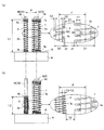
図7は、線径(断面径),単位長さ当たりのコイル巻数,巻径(内径)が異なる2つのコイルばね7,8を芯部材3a,3bに外嵌させた場合のモデル図である。コイルばね7,8は、線径(断面径),単位長さ当たりのコイル巻数,巻径が相違しているが、ばね定数は同じ(実質的に同一)である。   FIG. 7 is a model diagram when two coil springs 7 and 8 having different wire diameters (cross-sectional diameters), coil turns per unit length, and winding diameters (inner diameters) are externally fitted to the core members 3a and 3b. . The coil springs 7 and 8 have different wire diameters (cross-sectional diameters), coil turns per unit length, and winding diameters, but the spring constants are the same (substantially the same).

図7(a),図7(b)において、複式筆記具全体の描写は省略している。
ボールペンレフィルである芯部材3aの太さはW1であり、シャープペンシルユニットである芯部材3bの太さはW2である。芯部材3a(ボールペンレフィル)は、芯部材3b(シャープペンシルユニット)よりも太い(W1>W2)。芯部材3aの中心(軸芯)と、芯部材3bの中心(軸芯)の距離はFである。
In FIG. 7 (a) and FIG. 7 (b), depiction of the entire double writing instrument is omitted.
The thickness of the core member 3a that is the ballpoint pen refill is W1, and the thickness of the core member 3b that is the mechanical pencil unit is W2. The core member 3a (ball pen refill) is thicker than the core member 3b (mechanical pencil unit) (W1> W2). The distance between the center (axial core) of the core member 3a and the center (axial core) of the core member 3b is F.

ボールペンレフィル用コイルばね7のばね定数はK、線径(太さ)はd1、巻数はN1、自然状態のときの巻径(内径)はD1である。
ここで、巻数とは、ボールペンレフィル用コイルばね7の両端の座巻部分(7a,7b)や、必要に応じてコイルばね7の中央部分に形成される密集した部分を除く有効巻数である。すなわち、巻数とは、ボールペンレフィル用コイルばね7における伸縮方向(軸方向)に弾性変形する螺旋部分の周回数をカウントしたものである。
The spring constant of the ballpoint pen refill coil spring 7 is K, the wire diameter (thickness) is d1, the winding number is N1, and the winding diameter (inner diameter) in the natural state is D1.
Here, the number of turns is an effective number of turns excluding end turns (7a, 7b) at both ends of the ball-point refill coil spring 7 and a dense part formed at the center of the coil spring 7 as required. That is, the number of turns is obtained by counting the number of turns of the spiral portion that is elastically deformed in the expansion / contraction direction (axial direction) in the ball-point refill coil spring 7.

巻径D1(内径)は、ボールペンレフィル用コイルばね7が自然状態のときの寸法であるが、巻径D1は、ボールペンチップ20が突出位置に移動し、コイルばね7が圧縮変形した際に、当該コイルばね7が蛇行形状にならない、又は蛇行形状になりにくい大きさに設定されている。すなわち、コイルばね7が圧縮された際に、当該コイルばね7が複数方向に偏心しにくくなる様に、コイルばね7と芯部材3aのクリアランスC1が設定されている。芯部材3aの外径(太さ)をW1とすると、クリアランスC1は、C1=(D1−W1)/2となる。   The winding diameter D1 (inner diameter) is the dimension when the ballpoint pen refill coil spring 7 is in a natural state, but the winding diameter D1 is when the ballpoint pen tip 20 moves to the protruding position and the coil spring 7 is compressed and deformed. The coil spring 7 is set to a size that does not take a meandering shape or is difficult to take a meandering shape. That is, when the coil spring 7 is compressed, the clearance C1 between the coil spring 7 and the core member 3a is set so that the coil spring 7 is not easily eccentric in a plurality of directions. When the outer diameter (thickness) of the core member 3a is W1, the clearance C1 is C1 = (D1−W1) / 2.

図示していないが、ボールペンレフィル用コイルばね7の自然長はLである。
また、図7(a)に示す様に、コイルばね7の装着時長さ(ボールペンチップ20が軸筒2内に退入しているときの長さ)はL1(L1<L)である。すなわち、コイルばね7は、若干縮設されている。
Although not shown, the natural length of the ballpoint refill coil spring 7 is L.
As shown in FIG. 7A, the length when the coil spring 7 is mounted (the length when the ball-point pen tip 20 is retracted into the shaft cylinder 2) is L1 (L1 <L). That is, the coil spring 7 is slightly contracted.

一方、シャープペンシルユニット用コイルばね8のばね定数はK、線径はd2、巻数はN2、自然状態のときの巻径(内径)はD2である。
ここで、巻数とは、コイルばね8の両端の座巻部分(8a,8b)や、必要に応じてコイルばね8の中央部分に形成される密集した部分を除く有効巻数である。すなわち、巻数とは、コイルばね8における伸縮方向(軸方向)に弾性変形する螺旋部分の周回数をカウントしたものである。
On the other hand, the mechanical constant of the mechanical pencil unit coil spring 8 is K, the wire diameter is d2, the number of turns is N2, and the winding diameter (inner diameter) in the natural state is D2.
Here, the number of turns is an effective number of turns excluding end turns (8a, 8b) at both ends of the coil spring 8 and a dense part formed at the center of the coil spring 8 as required. That is, the number of turns is obtained by counting the number of turns of the spiral portion that is elastically deformed in the expansion / contraction direction (axial direction) of the coil spring 8.

線径d2は、コイルばね7の線径d1よりも大きい(d2>d1)。   The wire diameter d2 is larger than the wire diameter d1 of the coil spring 7 (d2> d1).

巻径D2(内径)は、シャープペンシルユニット用コイルばね8が自然状態のときの寸法であるが、巻径D2は、コイルばね8が圧縮変形した際に、当該コイルばね8が蛇行形状にならない、又は蛇行形状になりにくい大きさに設定されている。すなわち、コイルばね8が圧縮された際に、当該コイルばね8が複数方向に偏心しにくくなる様に、コイルばね8と芯部材3bのクリアランスC2が設定されている。芯部材3bの外径(太さ)をW2とすると、クリアランスC2は、C2=(D2−W2)/2となる。   The winding diameter D2 (inner diameter) is a dimension when the mechanical pencil unit coil spring 8 is in a natural state. However, the winding diameter D2 is not meandering when the coil spring 8 is compressed and deformed. Or, it is set to a size that does not easily form a meandering shape. That is, when the coil spring 8 is compressed, the clearance C2 between the coil spring 8 and the core member 3b is set so that the coil spring 8 is not easily eccentric in a plurality of directions. When the outer diameter (thickness) of the core member 3b is W2, the clearance C2 is C2 = (D2-W2) / 2.

図示していないが、シャープペンシルユニット用コイルばね8の自然長はLである。
また、図7(a)に示す様に、コイルばね8の装着時長さ(ペン先ユニット31が軸筒2内に退入しているときの長さ)はL1(L1<L)である。すなわち、コイルばね8は、若干縮設されている。
Although not shown, the natural length of the mechanical pencil unit coil spring 8 is L.
As shown in FIG. 7A, the length when the coil spring 8 is mounted (the length when the pen tip unit 31 is retracted into the shaft cylinder 2) is L1 (L1 <L). . That is, the coil spring 8 is slightly contracted.

シャープペンシルユニット用コイルばね8とボールペンレフィル用コイルばね7を比較すると、以下の様である。
コイルばね7,8の長さは同じLである。
コイルばね7,8のばね定数Kは実質的に同一である。
ここで、「実質的に同一」とは、コイルばね7,8の製造誤差等を考慮して同一の範囲と言えるものであることを意味している。
コイルばね8の線径d2は、コイルばね7の線径d1よりも大きい(d2>d1)。
コイルばね8の巻径D2は、コイルばね7の巻径D1よりも小さい(D2<D1)。
また、図7(a)では、詳しく示していないが、コイルばね8の単位長さ当たりの巻数N2は、コイルばね7の単位長さ当たりの巻数N1よりも多い(N2>N1)。
The mechanical pencil unit coil spring 8 and the ballpoint pen refill coil spring 7 are compared as follows.
The lengths of the coil springs 7 and 8 are the same L.
The spring constants K of the coil springs 7 and 8 are substantially the same.
Here, “substantially the same” means that the same range can be said in consideration of manufacturing errors of the coil springs 7 and 8.
The wire diameter d2 of the coil spring 8 is larger than the wire diameter d1 of the coil spring 7 (d2> d1).
The winding diameter D2 of the coil spring 8 is smaller than the winding diameter D1 of the coil spring 7 (D2 <D1).
Although not shown in detail in FIG. 7A, the number of turns N2 per unit length of the coil spring 8 is larger than the number of turns N1 per unit length of the coil spring 7 (N2> N1).

次に、コイルばね7,8と、芯部材3a,3bの位置関係について図7(a)を参照しながら説明する。   Next, the positional relationship between the coil springs 7 and 8 and the core members 3a and 3b will be described with reference to FIG.

図7(a)に示す様に、コイルばね7は芯部材3aに外嵌されており、補助部材4と操作部材5の係合部44の間に装着されている。コイルばね7の装着時長さはL1(L1<L)である。コイルばね7は、圧縮ばねとして機能する。   As shown in FIG. 7A, the coil spring 7 is fitted on the core member 3 a and is mounted between the auxiliary member 4 and the engaging portion 44 of the operation member 5. The length when the coil spring 7 is mounted is L1 (L1 <L). The coil spring 7 functions as a compression spring.

また、コイルばね7の装着時長さはL1であり、ボールペンチップ20を突出口9(図2)から突出させたときの突出時長さはL2である。すなわち、コイルばね7の長さは、装着時長さL1から突出時長さL2の間で変化する。
換言すると、操作部材5のストロークは、L1−L2である。
Further, the length when the coil spring 7 is mounted is L1, and the length when protruding when the ball-point pen tip 20 is protruded from the protrusion 9 (FIG. 2) is L2. That is, the length of the coil spring 7 changes between the length L1 when mounted and the length L2 when protruded.
In other words, the stroke of the operation member 5 is L1-L2.

さらに、コイルばね7と芯部材3aのクリアランスC1は、C1=(D1−W1)/2である。すなわち、コイルばね7と芯部材3aの軸芯が一致している状態からコイルばね7は、芯部材3aに対してクリアランスC1だけ偏心する余地があるが、クリアランスC1は十分に小さく、ボールペンチップ20が軸筒2から突出してコイルばね7が圧縮されても、コイルばね7は、図8(b)に示す様に、蛇行形状になりにくい。   Further, the clearance C1 between the coil spring 7 and the core member 3a is C1 = (D1−W1) / 2. That is, there is room for the coil spring 7 to be eccentric from the core member 3a by the clearance C1 from the state in which the axial center of the coil spring 7 and the core member 3a coincides, but the clearance C1 is sufficiently small and the ballpoint pen tip 20 Even if the coil spring 7 protrudes from the shaft cylinder 2 and the coil spring 7 is compressed, the coil spring 7 is unlikely to have a meandering shape as shown in FIG.

図7(a)に示す様に、コイルばね8は芯部材3bに外嵌されており、補助部材4と操作部材45の係合部48の間に装着されている。コイルばね8の装着時長さはL1(L1<L)である。コイルばね8は、圧縮ばねとして機能する。   As shown in FIG. 7A, the coil spring 8 is fitted on the core member 3 b and is mounted between the auxiliary member 4 and the engaging portion 48 of the operation member 45. The length when the coil spring 8 is mounted is L1 (L1 <L). The coil spring 8 functions as a compression spring.

また、コイルばね8の装着時長さはL1であり、ペン先ユニット31を突出口9(図3)から突出させたときの突出時長さはL2である。すなわち、コイルばね7の長さは、装着時長さL1から突出時長さL2の間で変化する。   The length when the coil spring 8 is mounted is L1, and the length when protruding when the pen tip unit 31 is protruded from the protrusion 9 (FIG. 3) is L2. That is, the length of the coil spring 7 changes between the length L1 when mounted and the length L2 when protruded.

換言すると、操作部材45(クリップ6)のストロークは、L1−L2であり、操作部材5のストロークと同じである。そのため、芯部材3aを操作する操作部材5と、芯部材3bを操作する操作部材45の操作感は同様になる。   In other words, the stroke of the operation member 45 (clip 6) is L1-L2, which is the same as the stroke of the operation member 5. Therefore, the operation feeling of the operation member 5 that operates the core member 3a and the operation member 45 that operates the core member 3b are the same.

また、コイルばね8と芯部材3bのクリアランスC2は、C2=(D2−W2)/2である。すなわち、コイルばね8と芯部材3bの軸芯が一致している状態からコイルばね8は、芯部材3bに対してC2だけ偏心する余地があるが、クリアランスC2は十分に小さく、ペン先ユニット31が軸筒2から突出してコイルばね8が圧縮されても、コイルばね8は、図7(b)に示す様に、蛇行形状になりにくい。   The clearance C2 between the coil spring 8 and the core member 3b is C2 = (D2−W2) / 2. That is, the coil spring 8 has room to be decentered by C2 with respect to the core member 3b from the state where the coil spring 8 and the core member 3b are aligned, but the clearance C2 is sufficiently small, and the nib unit 31 Even if the coil spring 8 protrudes from the shaft cylinder 2 and the coil spring 8 is compressed, the coil spring 8 is unlikely to have a meandering shape as shown in FIG.

図7(a)に示す状態では、いずれの芯部材3a,3bも軸筒2の突出口9(図1)から突出しておらず、複式筆記具1は筆記不能である。
図7(a)に示す複式筆記具1が筆記不能な状態、すなわち、全ての芯部材3a,3bが収納位置にあるときには、コイルばね7,8は、F−(d1+d2+(D1+D2)/2)だけ離間している。説明を簡略化するため、F−(d1+d2+(D1+D2)/2)=S1とする。
In the state shown in FIG. 7A, none of the core members 3a and 3b protrudes from the protruding port 9 (FIG. 1) of the shaft tube 2, and the dual writing instrument 1 cannot write.
When the dual writing instrument 1 shown in FIG. 7A is incapable of writing, that is, when all the core members 3a and 3b are in the storage position, the coil springs 7 and 8 are only F- (d1 + d2 + (D1 + D2) / 2). It is separated. In order to simplify the description, F− (d1 + d2 + (D1 + D2) / 2) = S1.

複式筆記具1は、次の様に動作する。
図1,図7(a)に示す状態、すなわち、いずれの芯部材3a,3bも軸筒2の突出口9(開口)から突出していない筆記不能な状態から、図3,図7(b)に示す状態、すなわち、芯部材3bのペン先ユニット31を突出口9から突出させた筆記可能な状態とする際には、使用者は、図6(a)に示す当該芯部材3bに対応する操作部材45(クリップ6)を操作する。すなわち、操作部材45(クリップ6)を前方へ移動させる。
The compound writing instrument 1 operates as follows.
From the state shown in FIG. 1 and FIG. 7A, that is, from the state in which none of the core members 3 a and 3 b protrudes from the projecting opening 9 (opening) of the shaft cylinder 2, FIG. In the state shown in FIG. 6, that is, when the pen tip unit 31 of the core member 3 b is projected from the protruding port 9, the user corresponds to the core member 3 b shown in FIG. The operating member 45 (clip 6) is operated. That is, the operation member 45 (clip 6) is moved forward.

その結果、操作部材45が複式筆記具1の先端方向(前側)に移動し、コイルばね8が操作部材45の係合部48に押圧されてさらに圧縮され、前後方向(軸芯方向)の長さがL2(L1>L2)となる。その際、コイルばね8は、軸芯方向に真っ直ぐに圧縮されるとは限らず、例えば図7(b)に示す様に偏る(座屈する)。   As a result, the operation member 45 moves in the distal direction (front side) of the dual writing instrument 1, and the coil spring 8 is pressed by the engaging portion 48 of the operation member 45 and further compressed, and the length in the front-rear direction (axial direction). Becomes L2 (L1> L2). At that time, the coil spring 8 is not necessarily compressed straight in the axial direction, but is biased (buckled), for example, as shown in FIG.

この場合、図7(a),図7(b)において拡大して示す様に、隣接するコイルばね7に対して、コイルばね8は、座屈せずに真っ直ぐに圧縮された場合と比較して、最大でコイルばね8と芯部材3bのクリアランスC2分だけ接近する。   In this case, as shown in an enlarged view in FIGS. 7A and 7B, the coil spring 8 is compared to the case where the coil spring 8 is compressed straight without buckling. The coil spring 8 and the core member 3b approach each other by the clearance C2 at the maximum.

ところが、芯部材3aよりも細い芯部材3bに外嵌されているコイルばね8の巻径(内径)D2は、芯部材3aに外嵌されているコイルばね7の巻径(内径)D1よりも小さく設定されており、コイルばね8と芯部材3bのクリアランスC2は、十分に小さい。   However, the winding diameter (inner diameter) D2 of the coil spring 8 fitted on the core member 3b thinner than the core member 3a is larger than the winding diameter (inner diameter) D1 of the coil spring 7 fitted on the core member 3a. The clearance C2 between the coil spring 8 and the core member 3b is sufficiently small.

そのため、コイルばね8は、蛇行形状になりにくく、また、隣接するコイルばね7にほとんど接近せず、図7(a),図7(b)に示す様に、両コイルばね7,8は、最も接近した場合でもS2=S1−C2だけ離間している。   Therefore, the coil spring 8 is less likely to have a meandering shape, and hardly approaches the adjacent coil spring 7, and as shown in FIGS. 7 (a) and 7 (b), both the coil springs 7 and 8 are Even when it is closest, it is separated by S2 = S1-C2.

また、ペン先ユニット31が、図3に示す様な軸筒2から突出した状態と、図1に示す様な軸筒2内に退入した状態になる際においても、両コイルばね7,8の間には、少なくとも間隔S2があり、両コイルばね7,8が接触することはない。
よって、シャープペンシルユニットである芯部材3bの突出と退入の動作は円滑であり、操作部材45(クリップ6)の操作感は良好である。
Further, when the nib unit 31 is projected from the shaft cylinder 2 as shown in FIG. 3 and retreated into the shaft cylinder 2 as shown in FIG. There is at least a distance S2 between them, and the coil springs 7 and 8 do not contact each other.
Therefore, the protruding and retracting operations of the core member 3b, which is a mechanical pencil unit, are smooth, and the operation feeling of the operation member 45 (clip 6) is good.

次に、芯部材3aのボールペンチップ20が、軸筒2の突出口9から突出する場合について説明する。   Next, the case where the ball-point pen tip 20 of the core member 3a projects from the projecting opening 9 of the shaft cylinder 2 will be described.

本実施形態の複式筆記具1では、図7(a)に示すコイルばね7は、図12に示す従来のコイルばね68と同一規格のものであり、さらに、図7(a)に示す隣接した芯部材(筆記芯)同士の中心間距離Fは、図12(a)に示す従来の複式筆記具の筆記芯同士の中心間距離Fと同じである。
そのため、突出位置に移動する芯部材3aに外嵌したコイルばね7は、座屈しても、隣接する他のコイルばね7に接触することはない。
In the dual writing instrument 1 of the present embodiment, the coil spring 7 shown in FIG. 7A is of the same standard as the conventional coil spring 68 shown in FIG. 12, and further, the adjacent core shown in FIG. 7A. The center-to-center distance F between the members (writing cores) is the same as the center-to-center distance F between the writing cores of the conventional dual writing instrument shown in FIG.
Therefore, even if the coil spring 7 fitted on the core member 3a that moves to the protruding position buckles, it does not come into contact with other adjacent coil springs 7.

ここで、図8(a)に示すコイルばね8は、図12(a)の左側に示すコイルばね68よりも巻径が小径であるため、コイルばね7,8の間隔S1は、図12(a)に示すコイルばね68同士の間隔S4よりも大きい。   Here, since the coil spring 8 shown in FIG. 8A has a smaller winding diameter than the coil spring 68 shown on the left side of FIG. 12A, the interval S1 between the coil springs 7 and 8 is as shown in FIG. It is larger than the interval S4 between the coil springs 68 shown in a).

すなわち、図8(b)に示す様に、コイルばね7が座屈した際におけるコイルばね7とコイルばね8の最も接近した部位の間隔S3は、図12(b)におけるコイルばね68同士の最も接近した部位の間隔S5よりも大きくなる。
そのため、図8(b)に示す様にコイルばね7が圧縮されて座屈しても、コイルばね7がコイルばね8に接触することはあり得ない。
よって、コイルばね7を圧縮する場合(ボールペンチップ20を突出口9から突出させる場合)においても、当該コイルばね7は、他のいずれのコイルばね7,8とも接触しない。
That is, as shown in FIG. 8B, when the coil spring 7 is buckled, the distance S3 between the coil spring 7 and the coil spring 8 that are closest to each other is the largest between the coil springs 68 in FIG. It becomes larger than the interval S5 between the close parts.
Therefore, even if the coil spring 7 is compressed and buckled as shown in FIG. 8B, the coil spring 7 cannot contact the coil spring 8.
Therefore, even when the coil spring 7 is compressed (when the ball-point pen tip 20 protrudes from the protrusion 9), the coil spring 7 does not contact any of the other coil springs 7 and 8.

また、図7(a)に示すコイルばね7と芯部材3aのクリアランスC1は、コイルばね7が圧縮されたときに蛇行形状になりにくい大きさに設定されている。そのため、図8(b)に示す様に、コイルばね7が圧縮されても、コイルばね7は蛇行変形しにくい。
その結果、操作部材5の操作は円滑であり、良好な使用感が得られる。
Moreover, the clearance C1 between the coil spring 7 and the core member 3a shown in FIG. 7A is set to a size that does not easily cause a meandering shape when the coil spring 7 is compressed. Therefore, as shown in FIG. 8B, even if the coil spring 7 is compressed, the coil spring 7 is hardly deformed meandering.
As a result, the operation of the operation member 5 is smooth and a good usability can be obtained.

コイルばね7,8の自然長や装着時長さは、必ずしも一致している必要はないが、伸縮のストロークが一致しているのが好ましい。すなわち、コイルばね7,8のばね定数と伸縮のストロークが同じであると、操作部材5,45の操作感が同様になり、好ましい。   The natural lengths of the coil springs 7 and 8 and the attached lengths do not necessarily need to match, but it is preferable that the expansion and contraction strokes match. That is, it is preferable that the spring constants of the coil springs 7 and 8 and the expansion / contraction strokes are the same because the operation feeling of the operation members 5 and 45 is the same.

図10は、ボールペンレフィル用コイルばねの具体的な実施例を示している。
図10に示すボールペンレフィル用コイルばね71は、両端部分に7巻の座巻部27,28(密集部)があり、中央部に8巻の密集部29がある。ボールペンレフィル用コイルばね71は、これらの座巻部27,28及び密集部29とは別に14巻有しており、総巻き数は36巻である。すなわち、ボールペンレフィル用コイルばね71の有効巻き数は14巻である。ボールペンレフィル用コイルばね71の巻き数は、これによらず、任意に設定することができる。ボールペンレフィル用コイルばね71の材質は、例えばステンレスを採用することができる。
FIG. 10 shows a specific example of a coil spring for ballpoint pen refill.
The ball-point pen refill coil spring 71 shown in FIG. 10 has seven end winding portions 27 and 28 (concentrated portions) at both end portions, and eight central portions 29 at the center portion. The ball-point refill coil spring 71 has 14 turns separately from the end winding parts 27 and 28 and the dense part 29, and the total number of turns is 36. That is, the effective number of turns of the ballpoint refill coil spring 71 is 14 turns. The number of turns of the ballpoint pen refill coil spring 71 can be arbitrarily set regardless of this. As the material of the coil spring 71 for ballpoint pen refill, for example, stainless steel can be adopted.

ボールペンレフィル用コイルばね71の自然長は、26.4mmであり、軸筒2内に装着され、ボールペンチップ20が軸筒2内に収納されている装着時長さ(取付時長さ)は、22.7mmである。そして、ボールペンチップ20を軸筒2の突出口9から突出させた状態(使用時長さ)は、8.4mmである。すなわち、軸筒2内のボールペンチップ20の移動距離(ストローク)は、14.3mmである。   The natural length of the ballpoint pen refill coil spring 71 is 26.4 mm, and the length when mounted (the length when mounted) in which the ballpoint pen tip 20 is housed in the shaft tube 2 is mounted in the shaft tube 2. 22.7 mm. And the state (length in use) which made the ball-point pen tip 20 project from the projection port 9 of the shaft cylinder 2 is 8.4 mm. That is, the moving distance (stroke) of the ball-point pen tip 20 in the shaft cylinder 2 is 14.3 mm.

図11は、シャープペンシルユニット用コイルばね72の具体的な実施例を示している。
シャープペンシルユニット用コイルばね72は、ボールペンレフィル用コイルばね71とは単位長さ当たりの巻き数,巻径が相違している。
FIG. 11 shows a specific example of the coil spring 72 for the mechanical pencil unit.
The mechanical pencil unit coil spring 72 is different from the ball pen refill coil spring 71 in the number of turns and the winding diameter per unit length.

すなわち、巻径が小さいコイルばね72の有効巻数は、巻径が大きいコイルばね71の有効巻数よりも多くすることにより、両コイルばね71,72のばね定数を実質的に同一にし易い。   That is, by making the effective number of turns of the coil spring 72 having a small winding diameter larger than the effective number of turns of the coil spring 71 having a large winding diameter, the spring constants of both the coil springs 71 and 72 can be made substantially the same.

具体的には、図11に示す様に、シャープペンシルユニット用コイルばね72は、両端部分に2巻の座巻部37,38(密集部)があり、中央部にも2巻の密集部39がある。シャープペンシルユニット用コイルばね72は、これらの座巻部37,38及び密集部39とは別に28巻有しており、総巻き数は34巻である。すなわち、シャープペンシルユニット用コイルばね72の有効巻き数は28巻である。   Specifically, as shown in FIG. 11, the mechanical pencil unit coil spring 72 has two end winding portions 37 and 38 (concentrated portions) at both ends, and two central portions 39 at the center portion. There is. The mechanical pencil unit coil spring 72 has 28 windings in addition to the end winding portions 37 and 38 and the dense portion 39, and the total number of windings is 34. In other words, the effective number of windings of the mechanical pencil unit coil spring 72 is 28.

シャープペンシルユニット用コイルばね72の座巻部を含む両端部分は、端部へいくほど若干拡径する拡径部36を構成している。   Both end portions including the end winding portion of the mechanical pencil unit coil spring 72 constitute a diameter-expanded portion 36 that slightly increases in diameter toward the end portion.

また、シャープペンシルユニット用コイルばね72の自然長は、28.0mmであり、ペン先ユニット31が軸筒2内に収納されているときの装着時長さ(取付時長さ)は、22.7mmである。そして、ペン先ユニット31を軸筒2の突出口9から突出させた状態(使用時長さ)は、8.4mmである。よって、軸筒2内のペン先ユニット31の移動距離(ストローク)は、14.3mmである。   The natural length of the mechanical pencil unit coil spring 72 is 28.0 mm, and when the pen tip unit 31 is housed in the shaft tube 2, the attached length (attached length) is 22. 7 mm. And the state (length in use) which made the nib unit 31 protrude from the protrusion port 9 of the axial cylinder 2 is 8.4 mm. Therefore, the moving distance (stroke) of the nib unit 31 in the shaft cylinder 2 is 14.3 mm.

すなわち、ボールペンレフィル用コイルばね71とシャープペンシルユニット用コイルばね72とでは、自然長が相違しているが、装着時長さ(ペン先が軸筒2から突出していない非筆記状態のときの長さ)とペン先が軸筒2から突出した筆記可能な状態のときの長さ(8.4mm)が一致しており、両コイルばね71,72の移動距離(14.3mm)は同じである。   In other words, the natural length of the coil spring 71 for the ballpoint pen refill and the coil spring 72 for the mechanical pencil unit are different, but the length at the time of mounting (the length in the non-writing state where the pen tip does not protrude from the shaft cylinder 2). )) And the length (8.4 mm) when the pen tip protrudes from the shaft cylinder 2 is in a writable state, and the moving distances (14.3 mm) of the coil springs 71 and 72 are the same. .

ボールペンレフィル用コイルばね71,シャープペンシルユニット用コイルばね72のばね定数は、共に0.0035kgf/mm(0.034N/mm)である。すなわち、ボールペンレフィル用コイルばね71,シャープペンシルユニット用コイルばね72のばね定数は同じである。   The spring constants of the ballpoint pen refill coil spring 71 and the mechanical pencil unit coil spring 72 are both 0.0035 kgf / mm (0.034 N / mm). That is, the spring constants of the ball pen refill coil spring 71 and the mechanical pencil unit coil spring 72 are the same.

両コイルばね71,72は、ばね定数と移動距離(ストローク)が同じであるので、複式筆記具の使用者は、ボールペンレフィルとシャープペンシルユニットのいずれを操作する際においても、同様の操作感が得られる。ただし、両コイルばね71,72の自然長は相違しているので、操作部材5,45を操作するのに要する押圧力には差がある。すなわち、装着時長さが同じ両コイルばね71,72のうち、自然長が長いコイルばね72の方が、大きな押圧力が必要である。しかし、ばね定数が同じであるので、芯部材の移動開始から移動終了に至る両コイルばね71,72の押圧力の変化の仕方は同じである。そのため、当該複式筆記具は、使用者に良好な使用感を与えることができる。   Since both the springs 71 and 72 have the same spring constant and moving distance (stroke), the user of the dual writing instrument can obtain the same operational feeling when operating either the ballpoint pen refill or the mechanical pencil unit. It is done. However, since the natural lengths of the coil springs 71 and 72 are different, there is a difference in the pressing force required to operate the operation members 5 and 45. That is, of the two coil springs 71 and 72 having the same length when mounted, the coil spring 72 having a longer natural length requires a larger pressing force. However, since the spring constants are the same, the method of changing the pressing force of both coil springs 71 and 72 from the start of movement of the core member to the end of movement is the same. Therefore, the compound writing instrument can give the user a good feeling of use.

複数のボールペンレフィルと一つのシャープペンシルユニットが混在している複式筆記具において、仮に、クリップ6が操作部材45に装着されておらず、全ての芯部材3a,3bを、同様の操作部材5で操作する場合においても、上述の様に、必要な押圧力に差を設けることにより、使用者は、特定の操作部材5に対応する芯部材3bが、シャープペンシルユニットであることを認識することができる。   In a compound writing instrument in which a plurality of ballpoint pen refills and one mechanical pencil unit are mixed, the clip 6 is not attached to the operation member 45, and all the core members 3a and 3b are operated by the same operation member 5. Even in this case, as described above, by providing a difference in the necessary pressing force, the user can recognize that the core member 3b corresponding to the specific operation member 5 is a mechanical pencil unit. .

芯部材3aと芯部材3bの外径(太さ)は相違しており、芯部材3aの方が太い。例えば、芯部材3aの外径は2.6mmであり、芯部材3bの外径は2.3mmである。これらの芯部材3a,3bには、以下の様なコイルばね71,72を装着することができる。   The core member 3a and the core member 3b have different outer diameters (thicknesses), and the core member 3a is thicker. For example, the outer diameter of the core member 3a is 2.6 mm, and the outer diameter of the core member 3b is 2.3 mm. Coil springs 71 and 72 as described below can be attached to these core members 3a and 3b.

芯部材3aに装着されるボールペンレフィル用コイルばね71の外径は3.05mmであり、内径は2.65mmであり、線径(太さ)は0.2mmである。
芯部材3bに装着されるシャープペンシルユニット用コイルばね72(両端の拡径部36を除く)の外径は3.1mmであり、内径は2.64mmであり、線径(太さ)は0.23mmである。
The ball pen refill coil spring 71 mounted on the core member 3a has an outer diameter of 3.05 mm, an inner diameter of 2.65 mm, and a wire diameter (thickness) of 0.2 mm.
The outer diameter of the mechanical pencil unit coil spring 72 (excluding the enlarged diameter portions 36 at both ends) attached to the core member 3b is 3.1 mm, the inner diameter is 2.64 mm, and the wire diameter (thickness) is 0. .23 mm.

すなわち、太さの細い芯部材3bには、内径が小さいコイルばね72が装着されている。
太さが細い芯部材3bに対して内径が小さいコイルばね72を装着することにより、芯部材3bとコイルばね72のクリアランスが小さくなり、コイルばね72が圧縮された際に、コイルばね72が蛇行変形したり、隣接する他のコイルばね71に接触しにくくなる。
That is, a coil spring 72 having a small inner diameter is attached to the thin core member 3b.
By attaching the coil spring 72 having a small inner diameter to the core member 3b having a small thickness, the clearance between the core member 3b and the coil spring 72 is reduced, and when the coil spring 72 is compressed, the coil spring 72 meanders. It becomes difficult to deform or to contact other adjacent coil springs 71.

また、コイルばね72の内径のみならず、外径を小さくしてもよい。すなわち、コイルばね72の外径が小さいと、隣接する他のコイルばね71との間隔が広くなり、他のコイルばね71と接触しにくくなる。例えば、コイルばね72の線径(太さ)を細くすると、コイルばね72の内径及び外径を共に小さくすることができ、効果が高い。   Further, not only the inner diameter of the coil spring 72 but also the outer diameter may be reduced. That is, when the outer diameter of the coil spring 72 is small, the distance between the adjacent coil springs 71 is widened, and the coil springs 72 are less likely to come into contact with the other coil springs 71. For example, if the wire diameter (thickness) of the coil spring 72 is reduced, both the inner diameter and the outer diameter of the coil spring 72 can be reduced, and the effect is high.

また、内径が小さいシャープペンシルユニット用コイルばね72の両端には拡径部36が設けられている。
コイルばね72は、両端の拡径部36によって、補助部材4の支持面19や、操作部材45の係合部48に対する着座が安定し、位置が固定され易い。そのため、コイルばね72の伸縮動作が安定する。
Further, enlarged diameter portions 36 are provided at both ends of the mechanical pencil unit coil spring 72 having a small inner diameter.
The coil spring 72 is easily seated on the support surface 19 of the auxiliary member 4 and the engaging portion 48 of the operation member 45 by the enlarged diameter portions 36 at both ends, and the position is easily fixed. Therefore, the expansion / contraction operation of the coil spring 72 is stabilized.

また、内径(巻径)が小さいコイルばね72の線径(太さ)は、内径(巻径)が大きいコイルばね71の線径(太さ)よりも太い。例えば、内径(巻径)が小さいコイルばね72の線径(太さ)は0.23mmであり、内径(巻径)が大きいコイルばね71の線径(太さ)は0.2mmである。
この様に、両コイルばね71,72の線径を設定することにより、両コイルばね71,72のばね定数を実質的に同一に設定し易い。
Further, the wire diameter (thickness) of the coil spring 72 having a small inner diameter (winding diameter) is thicker than the wire diameter (thickness) of the coil spring 71 having a large inner diameter (winding diameter). For example, the wire diameter (thickness) of the coil spring 72 having a small inner diameter (winding diameter) is 0.23 mm, and the wire diameter (thickness) of the coil spring 71 having a large inner diameter (winding diameter) is 0.2 mm.
Thus, by setting the wire diameters of the two coil springs 71 and 72, the spring constants of the two coil springs 71 and 72 can be easily set to be substantially the same.

上述の実施形態では、芯部材3a,3bが、ボールペンレフィル,シャープペンシルユニットである場合を示したが、本発明はこれによらず、様々な態様に応用することができる。例えば、全ての芯部材をボールペンレフィルとし、特定の色(例えば黒)を太くし、その他の色を細くしてもよい。また、太い芯部材3aの数と細い芯部材3bの数は、任意に設定可能である。例えば、5色ボールペンであれば、3色を太い芯部材3aとし、残りの2色を細い芯部材3bとするなど適宜振り分けてもよい。   In the above-described embodiment, the case where the core members 3a and 3b are ballpoint pen refills and mechanical pencil units has been described. However, the present invention can be applied to various modes regardless of this. For example, all the core members may be ballpoint pen refills, a specific color (for example, black) may be thickened, and other colors may be thinned. Further, the number of thick core members 3a and the number of thin core members 3b can be arbitrarily set. For example, in the case of a five-color ballpoint pen, the three colors may be assigned to the thick core member 3a, and the remaining two colors may be assigned to the thin core member 3b.

また、芯部材としては、例えば、タッチパネルを操作するためのタッチペンであってもよい。さらに、芯部材は、白色顔料を塗布して筆記した文字を修正する塗布具(所謂修正ペン)であってもよい。つまり、芯部材は、外部の筆記対象物に文字等(文字、図柄、記号)を筆記する用に供するもの、又は、筆記した文字を消去、修正に供するものである。   Further, as the core member, for example, a touch pen for operating the touch panel may be used. Further, the core member may be an applicator (so-called correction pen) that corrects a written character by applying a white pigment. That is, the core member is used for writing characters or the like (characters, designs, symbols) on an external writing object, or for erasing and correcting the written characters.

1 複式筆記具
2 軸筒
3a 芯部材(ボールペンレフィルの筆記芯)
3b 芯部材(シャープペンシルユニットの筆記芯)
5 操作部材(操作手段)
7 ボールペンレフィル用コイルばね
8 シャープペンシルユニット用コイルばね
9 突出口(開口)
20 ボールペンチップ(筆記部)
31 ペン先チップ(筆記部)
1 Duplex writing instrument 2 Shaft cylinder 3a Core member (Ball pen refill writing core)
3b Core member (writing core of mechanical pencil unit)
5 Operation members (operation means)
7 Coil spring for ballpoint pen refill 8 Coil spring for mechanical pencil unit 9 Protruding port (opening)
20 Ballpoint pen tip (writing part)
31 Nib tip (writing part)

Claims (5)

先端が開口し内部に中空部分を有する軸筒と、先端に筆記部を有する複数の筆記芯と、複数のコイルばねと、複数の操作手段を有し、
各筆記芯の外周部に前記コイルばねが装着された状態で前記複数の筆記芯が前記軸筒内に配されており、各筆記芯は前記コイルばねによって軸筒内部方向に向かって付勢されており、操作手段を操作することによって先端の開口から選択的に筆記芯を突出させる複式筆記具において、
複数のコイルばねには、ばね定数が実質的に同一であって内径又は外径が異なるものがあり、
前記筆記芯には太さが異なるものが混在し、太さの細い筆記芯には内径又は外径の少なくとも一方が小さいコイルばねが装着されていることを特徴とする複式筆記具。
A shaft cylinder having an open tip and a hollow portion inside, a plurality of writing cores having a writing portion at the tip, a plurality of coil springs, and a plurality of operating means,
The plurality of writing cores are arranged in the shaft cylinder in a state where the coil springs are mounted on the outer peripheral portion of each writing core, and each writing core is urged toward the inside of the shaft cylinder by the coil springs. In the dual writing instrument that selectively protrudes the writing core from the opening at the tip by operating the operating means,
Some coil springs have substantially the same spring constant and different inner diameters or outer diameters.
What is different in thickness is mixed in the said writing core, and the coil writing spring with which at least one of an internal diameter or an outer diameter is small is mounted | worn with a thin writing core.
太さの細い筆記芯には内径が小さいコイルばねが装着されており、当該内径が小さいコイルばねの線径は、内径が大きいコイルばねの線径よりも太いことを特徴とする請求項1に記載の複式筆記具。   2. A coil spring having a small inner diameter is attached to the writing core having a small thickness, and the wire diameter of the coil spring having a small inner diameter is larger than the wire diameter of the coil spring having a large inner diameter. The double writing instrument described. 太さの細い筆記芯には内径が小さいコイルばねが装着されており、内径が小さいコイルばねの座巻き部分を除いた有効巻数は、内径が大きいコイルばねの座巻き部分を除いた有効巻数よりも多いことを特徴とする請求項1又は2に記載の複式筆記具。   A coil spring with a small inner diameter is attached to a thin writing core, and the effective number of turns excluding the coiled part of the coil spring with a small inner diameter is larger than the effective number of turns excluding the coiled part of the coil spring with a large inner diameter. The compound writing instrument according to claim 1 or 2, wherein there are also many. 太さの細い筆記芯には内径が小さいコイルばねが装着されており、内径が小さいコイルばねは、端部に拡径部を有していることを特徴とする請求項1乃至3のいずれかに記載の複式筆記具。   4. A coil spring having a small inner diameter is attached to a thin writing core, and the coil spring having a small inner diameter has an enlarged diameter portion at an end. A double writing instrument as described in 1. 太さが細い方の筆記芯が、シャープペンシルユニットであり、太さが太い方の筆記芯が、ボールペンレフィルであることを特徴とする請求項1乃至4のいずれかに記載の複式筆記具。   The compound writing instrument according to any one of claims 1 to 4, wherein the writing core having a smaller thickness is a mechanical pencil unit, and the writing core having a larger thickness is a ballpoint pen refill.
JP2016022159A 2016-02-08 2016-02-08 Compound writing instrument Active JP6713293B2 (en)

Priority Applications (1)

Application Number Priority Date Filing Date Title
JP2016022159A JP6713293B2 (en) 2016-02-08 2016-02-08 Compound writing instrument

Applications Claiming Priority (1)

Application Number Priority Date Filing Date Title
JP2016022159A JP6713293B2 (en) 2016-02-08 2016-02-08 Compound writing instrument

Publications (2)

Publication Number Publication Date
JP2017140716A true JP2017140716A (en) 2017-08-17
JP6713293B2 JP6713293B2 (en) 2020-06-24

Family

ID=59626965

Family Applications (1)

Application Number Title Priority Date Filing Date
JP2016022159A Active JP6713293B2 (en) 2016-02-08 2016-02-08 Compound writing instrument

Country Status (1)

Country Link
JP (1) JP6713293B2 (en)

Cited By (1)

* Cited by examiner, † Cited by third party
Publication number Priority date Publication date Assignee Title
JP2019119055A (en) * 2017-12-28 2019-07-22 三菱鉛筆株式会社 Mechanically extended type writing tool

Citations (5)

* Cited by examiner, † Cited by third party
Publication number Priority date Publication date Assignee Title
JPS5391823A (en) * 1977-01-22 1978-08-12 Ancos Co Ltd Knock type writing instrument
JP2002192890A (en) * 2000-10-19 2002-07-10 Mitsubishi Pencil Co Ltd Double writing utensil
WO2003004285A1 (en) * 2001-06-29 2003-01-16 Morris Pen Corporation Side click type composite writing instrument
JP2013075476A (en) * 2011-09-30 2013-04-25 Pentel Corp Duplex writing implement
JP2014162138A (en) * 2013-02-26 2014-09-08 Rui Anayama Multi-color writing tool

Patent Citations (5)

* Cited by examiner, † Cited by third party
Publication number Priority date Publication date Assignee Title
JPS5391823A (en) * 1977-01-22 1978-08-12 Ancos Co Ltd Knock type writing instrument
JP2002192890A (en) * 2000-10-19 2002-07-10 Mitsubishi Pencil Co Ltd Double writing utensil
WO2003004285A1 (en) * 2001-06-29 2003-01-16 Morris Pen Corporation Side click type composite writing instrument
JP2013075476A (en) * 2011-09-30 2013-04-25 Pentel Corp Duplex writing implement
JP2014162138A (en) * 2013-02-26 2014-09-08 Rui Anayama Multi-color writing tool

Cited By (1)

* Cited by examiner, † Cited by third party
Publication number Priority date Publication date Assignee Title
JP2019119055A (en) * 2017-12-28 2019-07-22 三菱鉛筆株式会社 Mechanically extended type writing tool

Also Published As

Publication number Publication date
JP6713293B2 (en) 2020-06-24

Similar Documents

Publication Publication Date Title
JP5196481B2 (en) Double writing instrument
WO2016002908A1 (en) Writing tool
JP6713293B2 (en) Compound writing instrument
JP2004136469A (en) Composite holder
JP5006110B2 (en) Writing instrument shaft structure
JP5593646B2 (en) Writing instrument
WO2015087852A1 (en) Ballpoint pen
JP5215768B2 (en) Writing instrument
JP6713292B2 (en) Compound writing instrument
JP5768638B2 (en) Double writing instrument
JP3946094B2 (en) Multi-core writing instrument
JP2009029028A (en) Retractable writing utensil
JP5731556B2 (en) Writing instrument
JP5433975B2 (en) Side knock type writing instrument
JP6259650B2 (en) Ballpoint pen
JP2020104339A (en) Writing instrument
EP4205993A1 (en) Slim writing implement with laterally offset return spring
JP2010042643A (en) Multi-refill writing instrument
JP4963456B2 (en) Multi-core writing instrument
JP6047194B2 (en) Writing instrument
JP2011025579A (en) Connecting structure with writing body in sliding member of multi-core writing instrument
JP2022055074A (en) Knock type writing tool
JP2021066137A (en) Writing instrument
JP2023144631A (en) Knock type writing instrument
JP3937858B2 (en) Rotating pay-out type composite writing instrument

Legal Events

Date Code Title Description
A80 Written request to apply exceptions to lack of novelty of invention

Free format text: JAPANESE INTERMEDIATE CODE: A80

Effective date: 20160301

A621 Written request for application examination

Free format text: JAPANESE INTERMEDIATE CODE: A621

Effective date: 20190205

A977 Report on retrieval

Free format text: JAPANESE INTERMEDIATE CODE: A971007

Effective date: 20191023

A131 Notification of reasons for refusal

Free format text: JAPANESE INTERMEDIATE CODE: A131

Effective date: 20191114

A521 Request for written amendment filed

Free format text: JAPANESE INTERMEDIATE CODE: A523

Effective date: 20191223

TRDD Decision of grant or rejection written
A01 Written decision to grant a patent or to grant a registration (utility model)

Free format text: JAPANESE INTERMEDIATE CODE: A01

Effective date: 20200528

A61 First payment of annual fees (during grant procedure)

Free format text: JAPANESE INTERMEDIATE CODE: A61

Effective date: 20200603

R150 Certificate of patent or registration of utility model

Ref document number: 6713293

Country of ref document: JP

Free format text: JAPANESE INTERMEDIATE CODE: R150