JP2017139921A - Rotator of rotary electric machine - Google Patents
Rotator of rotary electric machine Download PDFInfo
- Publication number
- JP2017139921A JP2017139921A JP2016020638A JP2016020638A JP2017139921A JP 2017139921 A JP2017139921 A JP 2017139921A JP 2016020638 A JP2016020638 A JP 2016020638A JP 2016020638 A JP2016020638 A JP 2016020638A JP 2017139921 A JP2017139921 A JP 2017139921A
- Authority
- JP
- Japan
- Prior art keywords
- rotor
- end plate
- rotor core
- rotating electrical
- electrical machine
- Prior art date
- Legal status (The legal status is an assumption and is not a legal conclusion. Google has not performed a legal analysis and makes no representation as to the accuracy of the status listed.)
- Granted
Links
Images


Classifications
-
- Y—GENERAL TAGGING OF NEW TECHNOLOGICAL DEVELOPMENTS; GENERAL TAGGING OF CROSS-SECTIONAL TECHNOLOGIES SPANNING OVER SEVERAL SECTIONS OF THE IPC; TECHNICAL SUBJECTS COVERED BY FORMER USPC CROSS-REFERENCE ART COLLECTIONS [XRACs] AND DIGESTS
- Y02—TECHNOLOGIES OR APPLICATIONS FOR MITIGATION OR ADAPTATION AGAINST CLIMATE CHANGE
- Y02T—CLIMATE CHANGE MITIGATION TECHNOLOGIES RELATED TO TRANSPORTATION
- Y02T10/00—Road transport of goods or passengers
- Y02T10/60—Other road transportation technologies with climate change mitigation effect
- Y02T10/64—Electric machine technologies in electromobility
Abstract
Description
この発明は、モータやジェネレータ等の回転電機に用いられるロータである回転子に関し、例えば、ハイブリッド自動車、燃料電池自動車等の電動車両に適用して好適な回転電機の回転子に関する。 The present invention relates to a rotor that is a rotor used in a rotating electric machine such as a motor or a generator, and relates to a rotor of a rotating electric machine that is suitable for application to an electric vehicle such as a hybrid vehicle or a fuel cell vehicle.
特許文献1には、円筒状のロータコアと、該ロータコアの周方向複数箇所にそれぞれV字状に配された2つの磁石片からなる極と、前記ロータコアの軸方向両端部で前記ロータコアを支持する銅等の導電体からなる一対のエンドプレートと、を備える回転電機の回転子が開示されている。 In Patent Document 1, a cylindrical rotor core, a pole made of two magnet pieces respectively arranged in a V shape at a plurality of circumferential positions of the rotor core, and the rotor core are supported by both axial ends of the rotor core. A rotor of a rotating electrical machine including a pair of end plates made of a conductor such as copper is disclosed.
前記エンドプレートの軸方向の側面(主面)には、複数の前記極(磁石片)の端部の全面に対向する位置に環状凹部が設けられ、この環状凹部により空間部(空隙)が形成されている。 On the side surface (main surface) in the axial direction of the end plate, an annular recess is provided at a position facing the entire surface of the end portions of the plurality of poles (magnet pieces), and a space (gap) is formed by the annular recess. Has been.
この空間部により、ロータコアからエンドプレートへの漏洩磁束の鎖交がし難くなり、エンドプレートでの渦電流の発生を抑制することができると記載されている(特許文献1の[0020])。 It is described that this space portion makes it difficult to link the leakage magnetic flux from the rotor core to the end plate, thereby suppressing the generation of eddy currents in the end plate ([0020] of Patent Document 1).
しかしながら、特許文献1に開示されたエンドプレートは、磁石片の対向面の全面(全周)に環状凹部による空隙を設けているため、エンドプレートで磁石片の軸方向への変位を規制する保証がなくなり、例えば、磁石片の外周をロータコアに固着する樹脂部材の劣化により、ロータの回転中、前記磁石片が軸方向に移動してしまうという課題があり改良の余地がある。 However, since the end plate disclosed in Patent Document 1 is provided with a space by an annular recess on the entire surface (entire circumference) of the opposing surface of the magnet piece, it is guaranteed that the end plate regulates the displacement of the magnet piece in the axial direction. For example, due to deterioration of the resin member that fixes the outer periphery of the magnet piece to the rotor core, there is a problem that the magnet piece moves in the axial direction during rotation of the rotor, and there is room for improvement.
この発明はこのような課題を考慮してなされたものであり、前記磁石片の軸方向への移動を確実に規制し、且つエンドプレートへの磁束の漏洩を効果的に低減することを可能とする回転電機の回転子を提供することを目的とする。 The present invention has been made in consideration of such problems, and can reliably restrict the movement of the magnet pieces in the axial direction and effectively reduce the leakage of magnetic flux to the end plate. An object of the present invention is to provide a rotor for a rotating electrical machine.
この発明に係る回転電機の回転子は、円筒状のロータコアと、該ロータコアの軸方向端部で前記ロータコアを支持する非磁性体のエンドプレートと、前記ロータコアの周方向複数箇所に配された少なくとも2つの直方体状の磁石片からなる極と、を有する回転電機の回転子において、前記ロータコアは、前記極内の前記磁石片間に位置する梁部を有し、前記エンドプレートは、少なくとも一部が前記磁石片を支持しており、且つ少なくとも前記梁部の軸方向側面に対向する面に凹部が形成されて、前記梁部の前記軸方向側面との間に空隙を有するように構成される。 A rotor of a rotating electrical machine according to the present invention includes a cylindrical rotor core, a non-magnetic end plate that supports the rotor core at an axial end portion of the rotor core, and at least a plurality of circumferential positions of the rotor core. In a rotor of a rotating electrical machine having a pole made of two rectangular parallelepiped magnet pieces, the rotor core has a beam portion positioned between the magnet pieces in the pole, and the end plate is at least partially Is configured to support the magnet piece, and at least a recess is formed on a surface facing the axial side surface of the beam portion, and a gap is formed between the beam side and the axial side surface. .
従来から、極を2つの磁石片に分割し、ロータコアの周方向複数箇所にV字型に配置することで、前記ロータコアの強度を確保しつつ、トルク増加を図る技術が知られている。 2. Description of the Related Art Conventionally, a technique for increasing torque while securing the strength of the rotor core is known by dividing the pole into two magnet pieces and arranging them in a V shape at a plurality of locations in the circumferential direction of the rotor core.
しかしながら、2つの磁石片をV字型に配置した場合は、磁束が前記V字型の中央先端部の梁部に集中し磁束飽和が発生しやすく、前記梁部からエンドプレートへの磁束漏洩が多くなり、エンドプレートに渦電流による損失が発生しやすくなる。 However, when the two magnet pieces are arranged in a V shape, the magnetic flux is concentrated on the beam portion at the center end portion of the V shape, and magnetic flux saturation is likely to occur, and magnetic flux leakage from the beam portion to the end plate occurs. This increases the amount of loss caused by eddy currents in the end plate.
一方、磁石片自体は透磁率が低く、磁束は透磁率の高いロータコアへ流れやすいため、エンドプレートへの磁束漏洩が少ない。 On the other hand, the magnet piece itself has a low magnetic permeability, and the magnetic flux easily flows to the rotor core having a high magnetic permeability, so that the magnetic flux leakage to the end plate is small.
そこで、この発明では、磁石片の軸方向側面中、梁部を除いた磁束漏洩が少ない軸方向側面の少なくとも一部(一部あるいは全部)をエンドプレートにより支持することで、磁石片の軸方向への移動・飛び出しを防止しつつ、前記梁部の軸方向側面の対向位置に形成したエンドプレートの凹部による空隙(透磁率の低い空気による空隙)で、効率良く効果的に磁束漏洩を低減し、ひいては回転電機の効率の向上を図る。 Therefore, in the present invention, the axial direction of the magnet piece is supported by supporting at least a part (a part or all) of the axial side surface with less magnetic flux leakage except for the beam portion by the end plate in the axial side surface of the magnet piece. The magnetic flux leakage is effectively and effectively reduced by the air gap (the air gap due to the low permeability) of the end plate formed at the position opposite the axial side surface of the beam while As a result, the efficiency of the rotating electrical machine is improved.
また、梁部の軸方向側面に対向するエンドプレート上の面を貫通孔ではなく、凹部の空隙としたことにより、磁石片の固定部材の破片が発生したとしても、前記凹部の空隙内に納まるため、前記破片を原因とする回転電機の故障を防止することができる。 Further, the surface on the end plate facing the side surface in the axial direction of the beam portion is not a through hole but a recess gap, so that even if a fragment of the fixing member of the magnet piece is generated, it fits in the recess gap. Therefore, it is possible to prevent a failure of the rotating electrical machine due to the fragments.
この場合、前記エンドプレートの前記梁部の軸方向側面に対向する面の前記凹部は、環状溝に形成してもよい。前記磁石片を軸方向側面から支持するエンドプレートの凹部を環状溝に形成することで、凹部をプレス加工や切削加工で容易に加工でき、コストを低減することができる。 In this case, you may form the said recessed part of the surface facing the axial direction side surface of the said beam part of the said end plate in an annular groove. By forming the concave portion of the end plate that supports the magnet piece from the axial side surface in the annular groove, the concave portion can be easily processed by pressing or cutting, and the cost can be reduced.
ここで、前記環状溝の前記凹部の内径は、前記梁部を形成する前記磁石片の内側角部を通る円の半径の長さよりも短く、前記環状溝の前記凹部の外径は、前記梁部を形成する前記磁石片の外側角部を通る円の半径の長さよりも長いことが好ましい。前記梁部の軸方向側面の全体を環状の空隙が覆うため、前記エンドプレートへの磁束漏洩をより少なくできる。 Here, the inner diameter of the concave portion of the annular groove is shorter than the radius of a circle passing through the inner corner of the magnet piece forming the beam portion, and the outer diameter of the concave portion of the annular groove is the beam It is preferable that the length of the radius of the circle passing through the outer corner of the magnet piece forming the portion is longer. Since the annular gap covers the entire axial side surface of the beam portion, magnetic flux leakage to the end plate can be further reduced.
なお、前記凹部は有底の中空円柱状としてもよい。有底の中空円柱状の凹部とすることで、必要最小限に近い空隙となり、前記エンドプレートの剛性が上がり、前記エンドプレートの板厚を薄くすることができる。また、切削加工も容易でコストを削減できる。 In addition, the said recessed part is good also as a hollow cylindrical shape with a bottom. By forming a hollow cylindrical recess with a bottom, the gap becomes a minimum necessary, the rigidity of the end plate is increased, and the plate thickness of the end plate can be reduced. Also, cutting is easy and the cost can be reduced.
ここで、有底の前記中空円柱状の前記凹部の円開口は前記梁部を覆う大きさとすることが好ましい。梁部全体を空隙が覆うため、磁束漏洩を少なくできる。 Here, it is preferable that the circular opening of the hollow cylindrical recess having a bottom has a size covering the beam portion. Since the gap covers the entire beam portion, magnetic flux leakage can be reduced.
また、この発明に係る回転電機の回転子は、円筒状のロータコアと、該ロータコアの軸方向端部で前記ロータコアを支持する非磁性体のエンドプレートと、前記ロータコアの周方向複数箇所に配された少なくとも2つの直方体状の磁石片からなる極と、を有する回転電機の回転子において、前記ロータコアは、前記極内の前記磁石片間に位置する梁部を有し、前記エンドプレートは、少なくとも一部が前記磁石片を支持しており、且つ前記梁部の軸方向側面に対向する面に開口が形成されているように構成される。 The rotor of the rotating electrical machine according to the present invention is arranged at a cylindrical rotor core, a nonmagnetic end plate that supports the rotor core at an axial end portion of the rotor core, and a plurality of locations in the circumferential direction of the rotor core. The rotor core has a beam portion positioned between the magnet pieces in the pole, and the end plate includes at least two poles made of at least two rectangular parallelepiped magnet pieces. A part thereof supports the magnet piece, and an opening is formed on a surface facing the axial side surface of the beam portion.
この構成によれば、ロータコア上の梁部の軸方向側面に対向するエンドプレートの面を開口(貫通孔)としているので、漏洩磁束をより低減することができる。開口は、必要最小限に近い大きさでよいので、エンドプレートの剛性が上がり、エンドプレートの板厚を薄くすることができる。 According to this configuration, since the surface of the end plate facing the axial side surface of the beam portion on the rotor core is an opening (through hole), the leakage magnetic flux can be further reduced. Since the opening may have a size close to a necessary minimum, the rigidity of the end plate can be increased and the thickness of the end plate can be reduced.
なお、前記開口を中空円柱状の開口とし、該中空円柱状の前記開口を前記梁部の軸方向側面を覆う大きさとすることで、梁部の軸方向側面全体を開口が覆うため、磁束漏洩を少なくできる。 The opening is a hollow cylindrical opening, and the hollow cylindrical opening is sized to cover the axial side surface of the beam portion, so that the opening covers the entire axial side surface of the beam portion. Can be reduced.
さらに、低透磁率の封止材料でエンドプレートの開口を塞ぐことにより、磁石片の固定部材の破片が発生したとしても、エンドプレートから外部に前記破片が飛び出すことがなく、前記破片を原因とする回転電機の故障を防止することができる。 Furthermore, even if a fragment of the fixing member of the magnet piece occurs by closing the opening of the end plate with a low magnetic permeability sealing material, the fragment does not jump out of the end plate, causing the fragment. Failure of the rotating electric machine can be prevented.
この発明によれば、磁石片の軸方向側面中、梁部を除いた磁束漏洩が少ない軸方向側面の少なくとも一部(一部あるいは全部)をエンドプレートにより支持することで、前記磁石片の軸方向への移動・飛び出しを確実に規制し、前記梁部の軸方向側面の対向位置に形成したエンドプレートの凹部による空隙(透磁率の低い空気による空隙)で、効果的に磁束漏洩を低減することができる。 According to this invention, at least a part (part or all) of the axial side surface with less magnetic flux leakage excluding the beam portion in the axial side surface of the magnet piece is supported by the end plate, thereby the axis of the magnet piece. The magnetic flux leakage is effectively reduced by the air gap (the air gap by the low permeability) formed by the concave portion of the end plate formed at the opposite position of the axial side surface of the beam portion. be able to.
以下、この発明に係る回転電機の回転子について好適な実施形態を挙げ、添付の図面を参照して詳細に説明する。 Hereinafter, preferred embodiments of a rotor of a rotating electrical machine according to the present invention will be described in detail with reference to the accompanying drawings.
図1は、この実施形態に係る回転子としてのロータ12が組み込まれた回転電機としてのモータ10の一部省略断面構成を示す。
FIG. 1 shows a partially omitted cross-sectional configuration of a
モータ10は、図示しないハウジングに固定された固定子としてのステータ14と、このステータ14に対し、空隙18を空けて内側に配置されたロータ12とから構成される。
The
ロータ12は、前記ハウジング(不図示)に対し回転可能に支持される回転軸16と、磁性鋼板が積層され且つ積層された前記磁性鋼板中に磁石片24が埋め込み固定された円筒状のロータコア20と、該ロータコア20の軸方向側面を支持する銅又はアルミニウム等の非磁性体からなる一対のエンドプレート22と、一方のエンドプレート22を支持するカラー25と、を備える。
The
ロータ12は、回転軸16に対し、図1中、右側から他方のエンドプレート22、ロータコア20、一方の前記エンドプレート22、及びカラー25の順に挿入され、回転軸16に固定される。
The
図2は、ロータコア20のエンドプレート22に対向する面の一部切欠構成を示す。
FIG. 2 shows a partially cut-away configuration of the surface of the
図3は、図2のロータコア20の一部切欠構成に対向するエンドプレート22の一部切欠構成を示す。
FIG. 3 shows a partially cutaway configuration of the
図4は、図2のロータコア20のIV−IV線断面構成を含む一部省略断面拡大構成を示す。
FIG. 4 shows a partially omitted cross-sectional enlarged configuration including a cross-sectional configuration taken along line IV-IV of the
図2に示すように、ロータコア20には、いわゆるV字状に配置された3つの磁石片24(24a、24b、24c)からなる極26(S極又はN極)が複数個周方向に埋め込まれている。極26は、3つではなく、2つ以上の複数の直方体状の磁石片24をV字状に配置した構成としてもよい。
As shown in FIG. 2, a plurality of poles 26 (S poles or N poles) made of three magnet pieces 24 (24a, 24b, 24c) arranged in a so-called V shape are embedded in the
ロータコア20の極26内の中央の磁石片24aと、一方の側の磁石片24bとの間、及び中央の磁石片24aと、他方の側の磁石片24cとの間には、積層磁性鋼板からなる梁部28が形成される。
Between the
磁石片24が埋め込まれるロータコア20の磁石片24の長さ方向(図2中、紙面と直交する方向で軸方向と同方向)の外周には、フラックスバリア30を含む貫通孔である埋め込み用開口32が形成されている。この埋め込み用開口32に磁石片24がそれぞれ挿入され、磁石片24の埋め込み用開口32の隙間に樹脂材36が充填され固化されることで、固定部材としての固化された樹脂材36を介して磁石片24がロータコア20に固着される。
On the outer periphery in the length direction of the
図3及び図4に示すように、両エンドプレート22の軸方向のロータコア20に対向する面(対向面)40には、ロータコア20に形成された梁部28の軸方向側面(図2に現れている面、以下、便宜的に梁部28ともいう。)に対向する位置に中空円柱状の凹部42(理解の便宜のために、有底の凹部42ともいう。)が設けられ、前記梁部28との間に空隙44を有するように構成されている。
As shown in FIG. 3 and FIG. 4, the axial side surface (appearing surface) 40 of both
なお、図2において、各梁部28を囲むように二点鎖線で描いた円は、エンドプレート22に設けられた凹部42の円縁のロータコア20の軸方向側面に対する当接部分である円周46を模式的に示している。
In FIG. 2, a circle drawn by a two-dot chain line so as to surround each
すなわち、エンドプレート22に設けられた中空円柱状の凹部42の円周46を有する円は、梁部28の軸方向側面を覆う大きさとしている。凹部42は、中空円柱状の他、中空直方体状、中空半球状としてもよい。
That is, the circle having the
エンドプレート22の、ロータコア20の磁石片24の対向面40中、凹部42を除く面(支持面40Aという。)は、磁石片24の側部(長さ方向端面)に当接し、磁石片24を支持するとともに、ロータコア20を支持する。
Of the
このようにして、磁石片24の側部の梁部28を除いた漏洩磁束が少ない側部(磁石片24の軸方向側面)をエンドプレート22の支持面40Aにより支持することで、磁石片24の軸方向への移動・飛び出しを防止しつつ、梁部28の軸方向側面の対向位置に形成した凹部42による空隙44で、梁部28からの磁束漏洩を効率良く低減できる。これにより、回転電機としてのモータ10の効率の向上を図ることができる。
In this way, by supporting the side portion (side surface in the axial direction of the magnet piece 24) with less leakage magnetic flux except for the
[実施形態のまとめ及び変形例並びに他の実施形態及び変形例]
実施形態に係るモータ10のロータ12は、円筒状のロータコア20と、ロータコア20の軸方向端部で前記ロータコア20を支持する非磁性体のエンドプレート22と、ロータコア20の周方向複数箇所に配された磁石片24(24a、24b、24c)からなる極26と、を有する。
[Summary and Modifications of Embodiments and Other Embodiments and Modifications]
The
ロータコア20は、極26内の磁石片24a、24b、24c間に位置する梁部28(図2、図4)を有している。
The
エンドプレート22は、少なくとも一部、図2及び図3に示すように、この実施形態では、大部分の支持面40Aが磁石片24(24a、24b、24c)を支持しており、且つ少なくとも梁部28の軸方向側面に対向する面40に有底の凹部42が形成されて、梁部28の軸方向側面との間に空隙44(図4)を有するように構成されている。
The
図2に示したように、極26を3つの磁石片24a、24b、24cに分割し、V字型に配置した場合は、磁束が磁石片24a、24b間の梁部28及び磁石片24a、24c間の梁部28に集中し、磁気飽和が発生し易くなり、凹部42を設けていない場合、梁部28からエンドプレート22側への漏洩磁束が多くなる。
As shown in FIG. 2, when the
一方、磁石片24a、24b、24c自体は透磁率が低く、磁束は透磁率の高いロータコア20へ流れやすいため、磁石片24a、24b、24cの側部である長さ方向の端面からのエンドプレート22側への漏洩磁束は少ない。
On the other hand, the
そこで、実施形態では、磁石片24の側部(磁石片24の軸方向側面である磁石片24の長さ方向端面)の梁部28を除いた磁束漏洩が少ない側部(磁石片24の軸方向側面)の大部分をエンドプレート22の支持面40Aにより支持することで、磁石片24の軸方向側部への移動・飛び出しを防止しつつ、梁部28の軸方向側面の対向位置に形成した凹部42による空隙44(透磁率の低い空気による空隙44)により、磁束漏洩を効率良く低減し、ひいてはモータ10の効率の向上を図るようにしている。
Therefore, in the embodiment, the side portion (the axis of the magnet piece 24) with less magnetic flux leakage excluding the
また、梁部28の軸方向側面に対向するエンドプレート22上の面40を貫通孔ではなく、有底の凹部42からなる空隙44としたことにより、磁石片24の固定部材(ここでは樹脂材36)の破片が発生したとしても、凹部42の空隙44内に納まるため、前記破片を原因とするモータ10の故障を防止することができる。
Further, the
この場合において、エンドプレート22に設けた凹部42は、中空円柱状としているので必要最小限に近い円縁としての円周46を有する空隙44となり、従来技術に比較してエンドプレート22の剛性が上がり、エンドプレート22の板厚を薄くすることができる。
In this case, since the
この場合、中空円柱状の凹部42の円周46からなる円(円縁)は梁部28の軸方向側面を覆う大きさとしているので、梁部28の軸方向側面の全体が空隙44で覆われ、磁束漏洩を少なくできる。
In this case, since the circle (circle) formed by the
なお、中空円柱状の凹部42を設けたことによりロータコア20からの磁束漏洩量が、エンドプレート22に凹部42が設けられていないロータコアからの磁石漏洩量を100[%]として約80[%]程度に低減できることをシミュレーションにより確認している。
It should be noted that the magnetic flux leakage amount from the
<実施形態の変形例>
図5A及びそのVB−VB線断面図である図5Bに示すように、実施形態の変形例のロータ12A(全体図は、不図示)では、磁石片24の軸方向側面を支持するエンドプレート22Aの、ロータコア20の梁部28の軸方向側面に対向する面40の凹部47を、中空円柱状ではなく、環状溝の凹部47とし、この環状溝の凹部47からなる空隙44Aを形成している。
<Modification of Embodiment>
As shown in FIG. 5A and FIG. 5B, which is a cross-sectional view taken along the line VB-VB, in the
このように、磁石片24を側部から支持するエンドプレート22Aの凹部47を環状溝に形成することで、凹部47(環状溝)をプレス加工や切削加工で容易に加工でき、コストを低減することができる。
Thus, by forming the
図6は、変形例のロータ12Aを構成するロータコア20のエンドプレート22Aに対向する面の一部切り欠き構成を示す。図6において、梁部28を囲むように二点鎖線で描いた2つの円周は、エンドプレート22Aに設けられた前記環状溝のロータコア20の軸方向側面に当接する、凹部47(図5A、図5B)の溝縁の円周51、52を模式的に示している。
FIG. 6 shows a partially cut-out configuration of a surface facing the
凹部47の円周51を有する円の半径(内径)は、梁部28を構成する磁石片24の内側角部54を通る円の半径(この図6例では、磁石片24aの内側角部54を通る半径)の長さよりも短く、且つ凹部47の円周52を有する円の半径(外径)は、梁部28を構成する磁石片24の外側角部56を通る円の半径(この図6例では、磁石片24aの外側角部56を通る半径)の長さよりも長くする。
The radius (inner diameter) of the circle having the
このように構成すれば、凹部47の円周51を有する円の半径(内径)が、磁石片24aの軸方向への移動を可及的に防止するために磁石片24aのロータ12Aの半径方向内側部端部を通る円の半径の長さよりも長くなるので、エンドプレート22Aのロータコア20の軸方向側面に対向する面40中、磁石片24に当接する支持面40Aにより磁石片24の軸方向側部への移動・飛び出しを防止することができる。
With this configuration, the radius (inner diameter) of the circle having the
このように構成されたエンドプレート22Aは、梁部28の軸方向側面の全体を空隙44Aが覆うため、エンドプレート22Aへの磁束漏洩をより少なくできる。
In the
<他の実施形態>
図7及び図8に示すように、他の実施形態のロータ12Bでは、磁石片24の軸方向側面を支持するエンドプレート22Bの、ロータコア20の梁部28の軸方向側面に対向する面40の凹部を、中空円柱状ではなく、断面が扁平な長円状を呈する扁平な中空略直方体状の貫通孔の開口58としている。
<Other embodiments>
As shown in FIGS. 7 and 8, in the
図1は、エンドプレート22Bにより支持されるロータコア20を備えるロータ12Bが組み込まれた回転電機としてのモータ10の一部省略断面構成を示す。
FIG. 1 shows a partially omitted cross-sectional configuration of a
他の実施形態に係るロータ12Bは、円筒状のロータコア20と、該ロータコア20の軸方向端部でロータコア20を支持する非磁性体のエンドプレート22Bと、ロータコア20の周方向複数箇所に配された少なくとも2つ、ここでは3つの直方体状の磁石片24a、24b、24cからなる極26(図7)と、を有する。
The
この他の実施形態のロータ12Bにおいても、ロータコア20は、極26内の磁石片24aと磁石片24b及び磁石片24aと磁石片24c間に位置する梁部28(図7)を有する。
Also in the
図8に示すように、エンドプレート22Bは、ロータコア20の軸方向側面に対向する面40上、梁部28(図7)の軸方向側面に対向する面に、4角が丸くされた扁平な中空直方体状の開口(貫通孔)58が形成されている。エンドプレート22Bの開口58を除く面が、ロータコア20の磁石片24の側部に当接して支持する支持面40Bとされている。
As shown in FIG. 8, the
なお、図7において、各梁部28を囲むように二点鎖線で描いた長円は、エンドプレート22Bに設けられた開口58の開口縁のロータコア20の軸方向側面に対する当接部分である周縁60を模式的に示している。
In FIG. 7, an ellipse drawn with a two-dot chain line so as to surround each
他の実施形態に係るロータ12Aでは、ロータコア20上の梁部28の軸方向側面に対向するエンドプレート22Bの面を開口58としているので、ロータコア20からの漏洩磁束をより低減することができる。
In the
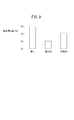
図9に示すように、中空円柱状の有底の凹部42を設けたときのロータコア20からの磁束漏洩量(漏洩磁束量)が、エンドプレート22に凹部42も開口58も設けられていないロータコアからの磁石漏洩量を100[%]として、約80[%]程度に低減できることに対し、貫通孔である開口58を設けたことにより、さらに約60[%]程度にまで低減できることをシミュレーションにより確認している。
As shown in FIG. 9, the amount of magnetic flux leakage (leakage magnetic flux) from the
<他の実施形態の変形例>
図10及び図11に示すように、他の実施形態の変形例のロータ12Cでは、磁石片24の軸方向側面を支持するエンドプレート22Cの、ロータコア20の梁部28の軸方向側面に対向する面40の凹部を、扁平な中空略直方体状の貫通孔の開口58ではなく、中空円柱状の貫通孔の開口62に形成している。
<Modification of other embodiment>
As shown in FIGS. 10 and 11, in the
図1は、エンドプレート22Cにより支持されるロータコア20を備えるロータ12Cが組み込まれた回転電機としてのモータ10の一部省略断面構成を示す。
FIG. 1 shows a partially omitted cross-sectional configuration of a
このように、磁石片24を側部から支持するエンドプレート22Cの開口62を中空円柱状に形成することで、開口62をプレス加工や切削加工で容易に加工でき、コストを低減することができる。
Thus, by forming the
図10は、ロータコア20のエンドプレート22Cに対向する面の一部切り欠き構成を示す。
FIG. 10 shows a partially cut-away configuration of the surface of the
図10において、磁石片24aと磁石片24b間及び磁石片24aと磁石片24c間に形成された梁部28を囲むように二点鎖線で描いた2つの円は、エンドプレート22Cに設けられた開口62がロータコア20の軸方向側面に当接する開口縁の円周64を模式的に示している。
In FIG. 10, two circles drawn by a two-dot chain line so as to surround the
中空円柱状の開口62の円周64は梁部28の軸方向側面を覆う大きさとしている。このようにして、梁部28の軸方向側面全体を開口62が覆うため、磁束漏洩を少なくできる。
The
なお、開口58(図8)及び開口62(図11)を低透磁率の樹脂剤やゴム等の封止材料で塞ぐことが好ましい。 Note that it is preferable to close the opening 58 (FIG. 8) and the opening 62 (FIG. 11) with a sealing material such as a low magnetic permeability resin agent or rubber.
低透磁率の封止材料でエンドプレート22Bの開口58及びエンドプレート22Cの開口62を塞ぐことにより、磁石片24の固定部材の破片が発生したとしても、前記破片がエンドプレート22B、22Cから外部に飛び出すことがなく、前記破片を原因とするモータ10の故障を防止することができる。
Even if a broken piece of the fixing member of the
なお、この発明は、上述の実施形態に限らず、例えば、図7及び図8を参照して説明した、ロータコア20の軸方向側面に対向する面40上、梁部28(図7)の軸方向側面に対向する面に、扁平な中空直方体状の開口(貫通孔)58を形成したエンドプレート22B(図8参照)に代替して、梁部28を覆う長円状の周縁60(図7参照)を有し、4角が丸くされた扁平な中空直方体状の有底の凹部(図4参照)を形成したエンドプレートにする等、この明細書の記載内容に基づき、種々の構成を採り得ることはもちろんである。
The present invention is not limited to the above-described embodiment. For example, the axis of the beam portion 28 (FIG. 7) on the
10…モータ(回転電機) 12(12A、12B、12C)…ロータ
14…ステータ 20…ロータコア
22(22A、22B、22C)…エンドプレート
24(24a、24b、24c)…磁石片
26…極 28…梁部
40…面(対向面) 40A、40B…支持面
42、47…凹部 44、44A…空隙
46、51、52、64…円周 54…内側角部
56…外側角部 58、62…開口
60…周縁
DESCRIPTION OF
Claims (9)
該ロータコアの軸方向端部で前記ロータコアを支持する非磁性体のエンドプレートと、
前記ロータコアの周方向複数箇所に配された少なくとも2つの直方体状の磁石片からなる極と、
を有する回転電機の回転子において、
前記ロータコアは、前記極内の前記磁石片間に位置する梁部を有し、
前記エンドプレートは、
少なくとも一部が前記磁石片を支持しており、且つ
少なくとも前記梁部の軸方向側面に対向する面に凹部が形成されて、前記梁部の前記軸方向側面との間に空隙を有する
ことを特徴とする回転電機の回転子。 A cylindrical rotor core;
A non-magnetic end plate that supports the rotor core at an axial end of the rotor core;
A pole composed of at least two rectangular magnet pieces arranged at a plurality of locations in the circumferential direction of the rotor core;
In the rotor of the rotating electrical machine having
The rotor core has a beam portion located between the magnet pieces in the pole,
The end plate is
At least a portion supports the magnet piece, and at least a concave portion is formed on a surface facing the axial side surface of the beam portion, and a gap is formed between the beam side and the axial side surface. A rotor of a rotating electrical machine that is characterized.
前記エンドプレートの前記梁部の軸方向側面に対向する面の前記凹部は、環状溝に形成されている
ことを特徴とする回転電機の回転子。 In the rotor of the rotating electrical machine according to claim 1,
The rotor of the rotating electrical machine, wherein the concave portion of the surface of the end plate facing the axial side surface of the beam portion is formed in an annular groove.
前記環状溝の前記凹部の内径は、前記梁部を形成する前記磁石片の内側角部を通る円の半径の長さよりも短く、
前記環状溝の前記凹部の外径は、前記梁部を形成する前記磁石片の外側角部を通る円の半径の長さよりも長い
ことを特徴とする回転電機の回転子。 The rotor of the rotating electrical machine according to claim 2,
An inner diameter of the concave portion of the annular groove is shorter than a length of a radius of a circle passing through an inner corner of the magnet piece forming the beam portion,
An outer diameter of the concave portion of the annular groove is longer than a radius of a circle passing through an outer corner portion of the magnet piece forming the beam portion.
前記凹部は有底の中空円柱状である
ことを特徴とする回転電機の回転子。 In the rotor of the rotating electrical machine according to claim 1,
The concave portion has a bottomed hollow cylindrical shape.
有底の前記中空円柱状の前記凹部の円開口は前記梁部を覆う大きさである
ことを特徴とする回転電機の回転子。 The rotor of the rotating electrical machine according to claim 4,
A rotor of a rotating electrical machine, wherein a circular opening of the hollow cylindrical recess having a bottom is sized to cover the beam portion.
該ロータコアの軸方向端部で前記ロータコアを支持する非磁性体のエンドプレートと、
前記ロータコアの周方向複数箇所に配された少なくとも2つの直方体状の磁石片からなる極と、
を有する回転電機の回転子において、
前記ロータコアは、前記極内の前記磁石片間に位置する梁部を有し、
前記エンドプレートは、
少なくとも一部が前記磁石片を支持しており、且つ
前記梁部の軸方向側面に対向する面に開口が形成されている
ことを特徴とする回転電機の回転子。 A cylindrical rotor core;
A non-magnetic end plate that supports the rotor core at an axial end of the rotor core;
A pole composed of at least two rectangular magnet pieces arranged at a plurality of locations in the circumferential direction of the rotor core;
In the rotor of the rotating electrical machine having
The rotor core has a beam portion located between the magnet pieces in the pole,
The end plate is
A rotor of a rotating electrical machine, wherein at least a part supports the magnet piece, and an opening is formed in a surface facing the axial side surface of the beam portion.
前記開口は中空円柱状である
ことを特徴とする回転電機の回転子。 The rotor of the rotating electrical machine according to claim 6,
The opening is a hollow cylindrical shape. A rotor of a rotating electrical machine.
前記中空円柱状の前記開口は前記梁部の軸方向側面を覆う大きさである
ことを特徴とする回転電機の回転子。 The rotor of the rotating electrical machine according to claim 7,
The rotor of the rotating electrical machine, wherein the hollow cylindrical opening has a size covering an axial side surface of the beam portion.
前記開口を低透磁率の封止材料で塞いだ
ことを特徴とする回転電機の回転子。 In the rotor of the rotary electric machine according to any one of claims 6 to 8,
A rotor of a rotating electrical machine, wherein the opening is closed with a sealing material having a low magnetic permeability.
Priority Applications (1)
| Application Number | Priority Date | Filing Date | Title |
|---|---|---|---|
| JP2016020638A JP6209630B2 (en) | 2016-02-05 | 2016-02-05 | Rotating electrical machine rotor |
Applications Claiming Priority (1)
| Application Number | Priority Date | Filing Date | Title |
|---|---|---|---|
| JP2016020638A JP6209630B2 (en) | 2016-02-05 | 2016-02-05 | Rotating electrical machine rotor |
Publications (2)
| Publication Number | Publication Date |
|---|---|
| JP2017139921A true JP2017139921A (en) | 2017-08-10 |
| JP6209630B2 JP6209630B2 (en) | 2017-10-04 |
Family
ID=59566923
Family Applications (1)
| Application Number | Title | Priority Date | Filing Date |
|---|---|---|---|
| JP2016020638A Active JP6209630B2 (en) | 2016-02-05 | 2016-02-05 | Rotating electrical machine rotor |
Country Status (1)
| Country | Link |
|---|---|
| JP (1) | JP6209630B2 (en) |
Citations (6)
| Publication number | Priority date | Publication date | Assignee | Title |
|---|---|---|---|---|
| CN102157995A (en) * | 2011-04-13 | 2011-08-17 | 康平科技(苏州)有限公司 | Electromechanical rotor |
| CN102545430A (en) * | 2011-12-14 | 2012-07-04 | 大连钰霖电机有限公司 | Laminated magnetic pole of permanent magnet engine |
| US20150102694A1 (en) * | 2013-10-16 | 2015-04-16 | Hyundai Mobis Co., Ltd. | Rotor structure of electric motor, and method for manufacturing the same |
| JP2015204653A (en) * | 2014-04-11 | 2015-11-16 | 本田技研工業株式会社 | Rotary electric machine |
| JP2016005306A (en) * | 2014-06-13 | 2016-01-12 | 株式会社オティックス | Rotary electric machine rotor |
| JP2016005308A (en) * | 2014-06-13 | 2016-01-12 | 株式会社オティックス | Rotary electric machine rotor |
-
2016
- 2016-02-05 JP JP2016020638A patent/JP6209630B2/en active Active
Patent Citations (6)
| Publication number | Priority date | Publication date | Assignee | Title |
|---|---|---|---|---|
| CN102157995A (en) * | 2011-04-13 | 2011-08-17 | 康平科技(苏州)有限公司 | Electromechanical rotor |
| CN102545430A (en) * | 2011-12-14 | 2012-07-04 | 大连钰霖电机有限公司 | Laminated magnetic pole of permanent magnet engine |
| US20150102694A1 (en) * | 2013-10-16 | 2015-04-16 | Hyundai Mobis Co., Ltd. | Rotor structure of electric motor, and method for manufacturing the same |
| JP2015204653A (en) * | 2014-04-11 | 2015-11-16 | 本田技研工業株式会社 | Rotary electric machine |
| JP2016005306A (en) * | 2014-06-13 | 2016-01-12 | 株式会社オティックス | Rotary electric machine rotor |
| JP2016005308A (en) * | 2014-06-13 | 2016-01-12 | 株式会社オティックス | Rotary electric machine rotor |
Also Published As
| Publication number | Publication date |
|---|---|
| JP6209630B2 (en) | 2017-10-04 |
Similar Documents
| Publication | Publication Date | Title |
|---|---|---|
| JP5353917B2 (en) | Rotating machine rotor | |
| US8487495B2 (en) | Rotor for motor | |
| JP6055725B2 (en) | Axial type rotating electric machine using rotor and rotor | |
| JP5930409B2 (en) | Rotating electric machine | |
| JP2012165481A (en) | Rotor for rotary electric machine | |
| EP2922178B1 (en) | Motor | |
| JP2006288185A (en) | Motor | |
| JP2016010176A (en) | Motor | |
| JP6210006B2 (en) | Axial gap type rotating electrical machine | |
| JPWO2018131393A1 (en) | Rotor for rotating electrical machines | |
| US20140210293A1 (en) | Permanent magnet embedded type rotor for rotating electrical machine and rotating electrical machine having permanent magnet embedded type rotor | |
| JP2014236576A (en) | Inner rotor motor | |
| JP2018057155A (en) | Rotator of rotating electrical machine | |
| JP2009261162A (en) | Split stator core | |
| JP2011147346A (en) | Electric motor | |
| JP6641545B1 (en) | Rotating electric machine | |
| JP2011172359A (en) | Split rotor and electric motor | |
| JP6209630B2 (en) | Rotating electrical machine rotor | |
| JP6327348B2 (en) | Rotating electric machine | |
| JP2011109786A (en) | Electric motor rotor | |
| JP2017046386A (en) | Permanent magnet electric motor | |
| JP2015220950A (en) | Rotating electrical machine | |
| WO2023238309A1 (en) | Rotary electric machine | |
| EP3364527A1 (en) | Electric motor and blower | |
| WO2023105701A1 (en) | Rotor of rotary electric machine |
Legal Events
| Date | Code | Title | Description |
|---|---|---|---|
| TRDD | Decision of grant or rejection written | ||
| A01 | Written decision to grant a patent or to grant a registration (utility model) |
Free format text: JAPANESE INTERMEDIATE CODE: A01 Effective date: 20170822 |
|
| A61 | First payment of annual fees (during grant procedure) |
Free format text: JAPANESE INTERMEDIATE CODE: A61 Effective date: 20170911 |
|
| R150 | Certificate of patent or registration of utility model |
Ref document number: 6209630 Country of ref document: JP Free format text: JAPANESE INTERMEDIATE CODE: R150 |