JP2017139902A - Current cutoff device and wire harness - Google Patents
Current cutoff device and wire harness Download PDFInfo
- Publication number
- JP2017139902A JP2017139902A JP2016019976A JP2016019976A JP2017139902A JP 2017139902 A JP2017139902 A JP 2017139902A JP 2016019976 A JP2016019976 A JP 2016019976A JP 2016019976 A JP2016019976 A JP 2016019976A JP 2017139902 A JP2017139902 A JP 2017139902A
- Authority
- JP
- Japan
- Prior art keywords
- current
- circuit
- fusible link
- electric wire
- cutoff
- Prior art date
- Legal status (The legal status is an assumption and is not a legal conclusion. Google has not performed a legal analysis and makes no representation as to the accuracy of the status listed.)
- Granted
Links
- 239000004065 semiconductor Substances 0.000 claims abstract description 44
- 239000004020 conductor Substances 0.000 claims description 19
- 238000011144 upstream manufacturing Methods 0.000 abstract description 29
- 230000002159 abnormal effect Effects 0.000 description 8
- 238000001514 detection method Methods 0.000 description 7
- 230000020169 heat generation Effects 0.000 description 7
- 238000010586 diagram Methods 0.000 description 3
- 238000012423 maintenance Methods 0.000 description 3
- 238000011156 evaluation Methods 0.000 description 2
- 239000000779 smoke Substances 0.000 description 2
- 230000005856 abnormality Effects 0.000 description 1
- 230000000903 blocking effect Effects 0.000 description 1
- 238000007796 conventional method Methods 0.000 description 1
- 238000013461 design Methods 0.000 description 1
- 230000005669 field effect Effects 0.000 description 1
- 239000000446 fuel Substances 0.000 description 1
- 239000000463 material Substances 0.000 description 1
- 239000000155 melt Substances 0.000 description 1
- 238000000034 method Methods 0.000 description 1
- 238000013021 overheating Methods 0.000 description 1
- 230000003071 parasitic effect Effects 0.000 description 1
- 230000005855 radiation Effects 0.000 description 1
Images


Classifications
-
- H—ELECTRICITY
- H02—GENERATION; CONVERSION OR DISTRIBUTION OF ELECTRIC POWER
- H02H—EMERGENCY PROTECTIVE CIRCUIT ARRANGEMENTS
- H02H3/00—Emergency protective circuit arrangements for automatic disconnection directly responsive to an undesired change from normal electric working condition with or without subsequent reconnection ; integrated protection
- H02H3/08—Emergency protective circuit arrangements for automatic disconnection directly responsive to an undesired change from normal electric working condition with or without subsequent reconnection ; integrated protection responsive to excess current
- H02H3/087—Emergency protective circuit arrangements for automatic disconnection directly responsive to an undesired change from normal electric working condition with or without subsequent reconnection ; integrated protection responsive to excess current for dc applications
-
- B—PERFORMING OPERATIONS; TRANSPORTING
- B60—VEHICLES IN GENERAL
- B60R—VEHICLES, VEHICLE FITTINGS, OR VEHICLE PARTS, NOT OTHERWISE PROVIDED FOR
- B60R16/00—Electric or fluid circuits specially adapted for vehicles and not otherwise provided for; Arrangement of elements of electric or fluid circuits specially adapted for vehicles and not otherwise provided for
- B60R16/02—Electric or fluid circuits specially adapted for vehicles and not otherwise provided for; Arrangement of elements of electric or fluid circuits specially adapted for vehicles and not otherwise provided for electric constitutive elements
- B60R16/03—Electric or fluid circuits specially adapted for vehicles and not otherwise provided for; Arrangement of elements of electric or fluid circuits specially adapted for vehicles and not otherwise provided for electric constitutive elements for supply of electrical power to vehicle subsystems or for
-
- H—ELECTRICITY
- H01—ELECTRIC ELEMENTS
- H01H—ELECTRIC SWITCHES; RELAYS; SELECTORS; EMERGENCY PROTECTIVE DEVICES
- H01H89/00—Combinations of two or more different basic types of electric switches, relays, selectors and emergency protective devices, not covered by any single one of the other main groups of this subclass
-
- H—ELECTRICITY
- H02—GENERATION; CONVERSION OR DISTRIBUTION OF ELECTRIC POWER
- H02H—EMERGENCY PROTECTIVE CIRCUIT ARRANGEMENTS
- H02H9/00—Emergency protective circuit arrangements for limiting excess current or voltage without disconnection
- H02H9/02—Emergency protective circuit arrangements for limiting excess current or voltage without disconnection responsive to excess current
- H02H9/025—Current limitation using field effect transistors
-
- H—ELECTRICITY
- H01—ELECTRIC ELEMENTS
- H01H—ELECTRIC SWITCHES; RELAYS; SELECTORS; EMERGENCY PROTECTIVE DEVICES
- H01H9/00—Details of switching devices, not covered by groups H01H1/00 - H01H7/00
- H01H9/10—Adaptation for built-in fuses
- H01H9/106—Adaptation for built-in fuses fuse and switch being connected in parallel
-
- H—ELECTRICITY
- H01—ELECTRIC ELEMENTS
- H01H—ELECTRIC SWITCHES; RELAYS; SELECTORS; EMERGENCY PROTECTIVE DEVICES
- H01H9/00—Details of switching devices, not covered by groups H01H1/00 - H01H7/00
- H01H9/54—Circuit arrangements not adapted to a particular application of the switching device and for which no provision exists elsewhere
- H01H9/541—Contacts shunted by semiconductor devices
Abstract
Description
本発明は、車両等の電源回路で異常な電流を遮断するために利用可能な電流遮断装置及びワイヤハーネスに関する。 The present invention relates to a current interrupt device and a wire harness that can be used to interrupt an abnormal current in a power supply circuit of a vehicle or the like.
一般に、車両には電源としてオルタネータ(発電機)やバッテリーが搭載されており、これらが供給する電源電力をワイヤハーネスを経由して負荷である様々な電装品にそれぞれ給電できるように構成されている。このような電源回路においては、故障の発生や短絡の発生などの際に、電源から負荷へ向かって異常に大きな電流が流れる可能性がある。また、もしも異常に大きな電流が流れ続けると、例えばワイヤハーネスの異常な発熱により、発煙や火災が生じる可能性も考えられる。そのため、例えば大電流が流れた時に溶断するヒューズを電源回路の途中に挿入するのが一般的である。 In general, a vehicle is equipped with an alternator (generator) and a battery as a power source, and is configured so that power supplied from these devices can be supplied to various electrical components as loads via a wire harness. . In such a power supply circuit, an abnormally large current may flow from the power supply to the load when a failure occurs or a short circuit occurs. Also, if an abnormally large current continues to flow, there is a possibility that smoke or fire may occur due to, for example, abnormal heat generation of the wire harness. Therefore, for example, a fuse that is blown when a large current flows is generally inserted in the middle of the power supply circuit.
また、車両の主要な電源回路に関しては、ワイヤハーネスの一部分にヒュージブルリンク(fusible link)と呼ばれる部品を挿入し、ワイヤハーネスの過熱を未然に防止する場合がある。ヒュージブルリンクは、大電流が流れて異常な発熱が生じる時に、ワイヤハーネスの他の箇所で破損が生じる前に溶断し、問題の発生を最小限に食い止めることができる。すなわち、ヒュージブルリンクを採用することにより、特定の部位以外でワイヤハーネスが異常発熱したり、破損するのを防止できるので、故障時のメンテナンスが容易になる。 In addition, regarding a main power supply circuit of a vehicle, a part called a fusible link may be inserted into a part of the wire harness to prevent overheating of the wire harness. When a large current flows and abnormal heat generation occurs, the fusible link is melted before breakage occurs at other parts of the wire harness, and the occurrence of problems can be minimized. That is, by adopting a fusible link, it is possible to prevent the wire harness from being abnormally heated or damaged outside a specific part, so that maintenance at the time of failure is facilitated.
電源における過大な電流に対する保護のための従来技術として、例えば特許文献1〜特許文献6が知られている。特許文献1に示されたUSB接続機器の入力保護回路は、抵抗器とヒューズとの直列回路を設けると共に、この直列回路と並列に、半導体スイッチを接続している。この入力保護回路は、突入電流の抑制、および過電流保護を行う機能を有し、電圧降下を減らすことを目的としている。
For example,
また、特許文献2に示された限流器は、主回路に半導体スイッチがあり、この主回路から分岐した箇所に1番目のヒューズが接続され、半導体スイッチと1番目のヒューズとが並列に接続されている。また、半導体スイッチがオフした後で、1番目のヒューズが溶断する。1番目のヒューズと並列に、2番目のヒューズと抵抗の回路が接続してある。2番目のヒューズは1番目のヒューズが溶断した後で溶断する。
In addition, the current limiter disclosed in
また、特許文献3に示されたインバータ装置においては、電源ラインに、抵抗器とヒューズとの直列回路と、これに並列に接続された電磁接触器のスイッチがある。そして、故障時にはスイッチを開いてヒューズを溶断させるようになっている。 Moreover, in the inverter apparatus shown by patent document 3, there exists a switch of the magnetic contactor connected to this in series with the series circuit of a resistor and a fuse in a power supply line. When a failure occurs, the switch is opened to blow the fuse.
また、特許文献4に示された車両用電源装置は、オンオフ可能なバイパス回路をヒューズと直列に接続してある。また、バイパス回路の電流容量をヒューズの電流容量よりも小さくするようになっている。 Further, in the vehicle power supply device disclosed in Patent Document 4, a bypass circuit that can be turned on / off is connected in series with a fuse. Further, the current capacity of the bypass circuit is made smaller than the current capacity of the fuse.
また、特許文献5に示された車両用電源遮断装置は、ヒューズと直列に半導体スイッチを接続している。また、障害発生時に半導体スイッチを制御してヒューズを確実に溶断させるようになっている。 In addition, the vehicle power shut-off device disclosed in Patent Document 5 has a semiconductor switch connected in series with a fuse. In addition, when a failure occurs, the semiconductor switch is controlled to surely blow the fuse.
また、特許文献6に示された直流遮断装置は、直流電源の給電部において、正極側ラインに半導体スイッチを接続すると共に、負極側ラインにヒューズを接続するようになっている。 In addition, the DC circuit breaker disclosed in Patent Document 6 is configured to connect a semiconductor switch to a positive line and a fuse to a negative line in a power supply unit of a DC power source.
ところで、ヒュージブルリンクを有する電源回路においては、過大な電流が流れた場合にワイヤハーネスの異常な発熱を防止して火災の発生を未然に防ぐために、ヒュージブルリンクが確実に溶断する必要がある。しかしながら、ヒュージブルリンクが溶断した場合には、部品の交換を行わない限り車両の機能を復旧させることができないので、頻繁にヒュージブルリンクが溶断するような事態は避けなければならない。 By the way, in a power supply circuit having a fusible link, the fusible link needs to be surely blown in order to prevent an abnormal heat generation of the wire harness and prevent a fire from occurring when an excessive current flows. . However, when the fusible link is melted, the function of the vehicle cannot be restored unless the parts are replaced. Therefore, a situation in which the fusible link frequently melts must be avoided.
そのため、例えば図3に示す例のように、オルタネータ(ALT)と、負荷およびバッテリーとの間にヒュージブルリンク(FL)が接続されている状況において、オルタネータの定格最大電流が150[A]の場合を想定すると、その2倍の300[A]の電流が流れたときに溶断するように、ヒュージブルリンクの遮断電流の仕様を決定し、ワイヤハーネスにおける火災の発生だけは確実に防ぐようになっている。 Therefore, for example, in the situation where the fusible link (FL) is connected between the alternator (ALT), the load and the battery as in the example shown in FIG. 3, the rated maximum current of the alternator is 150 [A]. Assuming the case, the fusible link cut-off current specification is determined so that the fuse blows when twice the current of 300 [A] flows, and only the occurrence of fire in the wire harness is surely prevented. It has become.
また、図3に示す例のように、ヒュージブルリンクの上流側とオルタネータとを接続する上流側電線101と、ヒュージブルリンクの下流側と負荷との間を接続する下流側電線102の各々の導電体の断面積については、ヒュージブルリンク以外の箇所でワイヤハーネスが溶断するのを避けるために、ヒュージブルリンクの電流仕様に合わせて決定する必要がある。もしも、ヒュージブルリンク以外の箇所が破損すると、ワイヤハーネス全体を交換しなければならず、メンテナンスのために大きな労力とコストがかかる。
Further, as in the example shown in FIG. 3, each of the upstream
具体的には、ヒュージブルリンクの遮断電流の仕様が300[A]の場合には、上流側電線101および下流側電線102の各々の導電体の断面積を、60[mm2]にする必要がある。つまり、非常に太く、しかも重い電線を上流側電線101および下流側電線102として採用しなければならない。したがって、ワイヤハーネスを車両上で配索する際の作業性が悪くなり、車両の燃費性能の低下にも繋がる。
Specifically, when the specification of the breakable current of the fusible link is 300 [A], the cross-sectional areas of the conductors of the
一方、特許文献1〜特許文献6に示されているような半導体スイッチや電磁接触器を、従来の機械的なヒュージブルリンクの代わりに利用することも考えられる。このような半導体スイッチ等を利用する場合には、過大電流に対して回路を遮断した後で、簡単に元の状態に復旧させることが可能である。したがって、遮断する電流値に大きな余裕を持たせる必要性がなくなる。
On the other hand, it is also conceivable to use a semiconductor switch or an electromagnetic contactor as shown in
例えば、図3に示した回路構成において、ヒュージブルリンクの代わりに半導体スイッチを利用する場合には、オルタネータ(ALT)の定格最大電流(150[A])に合わせて、半導体スイッチが遮断する定格電流を、150[A]にすることができる。また、その場合は、半導体スイッチの定格電流(150[A])に合わせて、上流側電線101および下流側電線102の各々の導電体の断面積を決定することになる。具体的には、導電体の断面積が30[mm2]の上流側電線101および下流側電線102を用いることができる。つまり、図3に示したように機械的なヒュージブルリンクを利用する場合と比べると、上流側電線101および下流側電線102の断面積を半分にできるので、ワイヤハーネスの細径化および重量の低減が見込まれる。
For example, in the circuit configuration shown in FIG. 3, when a semiconductor switch is used instead of the fusible link, the rating that the semiconductor switch cuts off in accordance with the rated maximum current (150 [A]) of the alternator (ALT). The current can be 150 [A]. In this case, the cross-sectional areas of the respective conductors of the upstream
しかし、実際に機械的なヒュージブルリンクの代わりに半導体スイッチを利用した電源回路を設計すると、新たな課題が生じることが判明した。具体的には、大電流の通電および遮断を許容できるように、多数の半導体スイッチを接続しなければならず、装置全体として、機械的なヒュージブルリンクを採用した場合よりも外形サイズが5倍程度に大きくなるという問題がある。 However, it has been found that when a power supply circuit using a semiconductor switch is actually designed instead of a mechanical fusible link, a new problem arises. Specifically, a large number of semiconductor switches must be connected so that energization and interruption of a large current can be permitted, and the overall size of the device is five times larger than when a mechanical fusible link is adopted. There is a problem that it becomes large.
本発明は、上述した事情に鑑みてなされたものであり、その目的は、ワイヤハーネスの細径化および重量の低減と共に、外形サイズの増大を抑制することが可能な電流遮断装置及びワイヤハーネスを提供することにある。 The present invention has been made in view of the above-described circumstances, and an object of the present invention is to provide a current interrupting device and a wire harness that can suppress an increase in outer size as well as reducing the diameter and weight of the wire harness. It is to provide.
前述した目的を達成するために、本発明に係る電流遮断装置及びワイヤハーネスは、下記(1)〜(5)を特徴としている。 In order to achieve the above-described object, a current interrupt device and a wire harness according to the present invention are characterized by the following (1) to (5).
(1) 所定以上の電流に対して物理的に回路を遮断する第1の電流遮断回路と、
少なくとも1つの半導体スイッチデバイスを有し、所定以上の電流に対して回路を遮断する第2の電流遮断回路と、を備え、
前記第1の電流遮断回路と前記第2の電流遮断回路とが並列に接続され、
所定の状況下において、前記第1の電流遮断回路に流れる電流と、前記第2の電流遮断回路に流れる電流との比率が、予め定めた規定値になるように構成されている、
電流遮断装置。
(2) 前記第1の電流遮断回路が、車両上に搭載されるワイヤハーネスに用いられるヒュージブルリンクである、
上記(1)に記載の電流遮断装置。
(3) 前記第2の電流遮断回路の電気抵抗値が、前記第1の電流遮断回路の電気抵抗値及び前記比率に基づいて決定される、
上記(2)に記載の電流遮断装置。
(4) 前記第2の電流遮断回路は、複数組の半導体スイッチデバイスが並列に接続された並列スイッチ回路により構成される、
上記(1)乃至(3)のいずれかに記載の電流遮断装置。
(5) 上記(1)乃至(4)のいずれかに記載の電流遮断装置と、
車両に搭載された発電機と前記電流遮断装置とを接続する第1の電線と、
前記電流遮断装置と前記車両に搭載された負荷またはバッテリーと接続される第2の電線と、を備え、
前記第1の電線の導体の断面積及び前記前記第2の電線の導体の断面積が、前記第1の電流遮断回路における定格遮断電流に応じて決定される、
ワイヤハーネス。
(1) a first current cut-off circuit that physically cuts the circuit against a predetermined current or more;
A second current interrupting circuit having at least one semiconductor switch device and interrupting the circuit with respect to a predetermined current or more,
The first current cutoff circuit and the second current cutoff circuit are connected in parallel;
Under a predetermined condition, the ratio of the current flowing through the first current cutoff circuit and the current flowing through the second current cutoff circuit is configured to be a predetermined specified value.
Current interrupt device.
(2) The first current interrupt circuit is a fusible link used for a wire harness mounted on a vehicle.
The electric current interruption apparatus as described in said (1).
(3) The electrical resistance value of the second current cutoff circuit is determined based on the electrical resistance value of the first current cutoff circuit and the ratio.
The electric current interruption apparatus as described in said (2).
(4) The second current interrupt circuit is configured by a parallel switch circuit in which a plurality of sets of semiconductor switch devices are connected in parallel.
The current interrupting device according to any one of (1) to (3).
(5) the current interrupting device according to any one of (1) to (4) above;
A first electric wire connecting a generator mounted on a vehicle and the current interrupting device;
A second electric wire connected to the current interrupting device and a load or battery mounted on the vehicle,
The cross-sectional area of the conductor of the first electric wire and the cross-sectional area of the conductor of the second electric wire are determined according to a rated breaking current in the first current breaking circuit;
Wire harness.
上記(1)の構成の電流遮断装置によれば、第1の電流遮断回路と第2の電流遮断回路とが並列回路を構成しているので、電源側から流入する電流は、第1の電流遮断回路の経路と、第2の電流遮断回路の経路とに分流した後、合流して、負荷側に流れる。したがって、例えば第1の電流遮断回路の経路に流れる電流が全体の50%であり、第2の電流遮断回路の経路に流れる電流も全体の50%であるような場合には、第1の電流遮断回路の電流の最大値(遮断電流の定格値)、および第2の電流遮断回路の電流の最大値(遮断電流の定格値)がそれぞれ半分になる。この場合、電流遮断装置全体の外形サイズは、第1の電流遮断回路だけの場合に比べて大きくなるが、第2の電流遮断回路だけの場合に比べて十分小さくなる。また、この電流遮断装置の上流側に接続する電線、および下流側に接続する電線の導電体の断面積は、第1の電流遮断回路の電流の最大値(遮断電流の定格値)により決まるので、第1の電流遮断回路だけの場合と比べて半分程度に削減できる。このような外形サイズと電線の導電体の断面積とを総合的に評価すると、第1の電流遮断回路、および第2の電流遮断回路のいずれか一方だけを用いて構成する場合と比べて顕著な優位性が認められる。
上記(2)の構成の電流遮断装置によれば、ヒュージブルリンクを用いるので、過電流が流れて回路の溶断が生じた時に、ワイヤハーネス上で遮断された箇所および部品の交換が必要な箇所を特定することが容易になる。また、ヒュージブルリンク以外の箇所で異常な発熱が生じるのを防止できる。
上記(3)の構成の電流遮断装置によれば、第1の電流遮断回路に流れる電流と、前記分流部から第2の電流遮断回路に流れる電流との比率を予め定めた規定値に定めることができる。したがって、第1の電流遮断回路における遮断電流の定格値、および第2の電流遮断回路における遮断電流の定格値を適切に定めることが可能である。更に、第1の電流遮断回路における遮断電流の定格値に基づき、電流遮断装置の上流側および下流側の電線の導電体の断面積を適切に定めることができる。
上記(4)の構成の電流遮断装置によれば、複数組の半導体スイッチデバイスを並列に接続することにより、第2の電流遮断回路を通過する電流に対する電気抵抗値を調整することが可能である。したがって、電流遮断装置を通過する全体の電流のうち、各々の経路に分流して流れる電流の比率を調整できる。
上記(5)の構成のワイヤハーネスによれば、ヒュージブルリンク以外の箇所で第1の電線および第2の電線に異常な発熱が生じたり、第1の電線および第2の電線が溶断することを防止できる。
According to the current interrupting device having the configuration of (1) above, since the first current interrupting circuit and the second current interrupting circuit constitute a parallel circuit, the current flowing from the power source side is the first current interrupting circuit. After diverting into the path of the breaking circuit and the path of the second current breaking circuit, they merge and flow to the load side. Therefore, for example, when the current flowing through the path of the first current cutoff circuit is 50% of the whole and the current flowing through the path of the second current cutoff circuit is also 50% of the whole, the first current The maximum value of the current of the breaking circuit (rated value of the breaking current) and the maximum value of the current of the second current breaking circuit (rated value of the breaking current) are each halved. In this case, the overall size of the current interrupting device is larger than that of the first current interrupting circuit alone, but is sufficiently smaller than that of the second current interrupting circuit alone. In addition, the cross-sectional area of the conductor connected to the upstream side of this current interrupting device and the conductor connected to the downstream side is determined by the maximum current value (the rated value of the interrupting current) of the first current interrupting circuit. As compared with the case of only the first current cutoff circuit, it can be reduced to about half. Comprehensive evaluation of the outer size and the cross-sectional area of the conductor of the electric wire is remarkable as compared with the case of using only one of the first current interrupt circuit and the second current interrupt circuit. The superiority is recognized.
Since the fusible link is used according to the current interrupting device having the configuration of (2) above, when an overcurrent flows and the circuit is blown out, the part interrupted on the wire harness and the part that needs to be replaced It becomes easy to specify. In addition, it is possible to prevent abnormal heat generation from occurring at locations other than the fusible link.
According to the current interrupting device having the configuration of (3) above, the ratio between the current flowing through the first current interrupting circuit and the current flowing from the shunt portion into the second current interrupting circuit is set to a predetermined specified value. Can do. Therefore, it is possible to appropriately determine the rated value of the cutoff current in the first current cutoff circuit and the rated value of the cutoff current in the second current cutoff circuit. Furthermore, based on the rated value of the breaking current in the first current breaking circuit, the cross-sectional areas of the conductors of the upstream and downstream wires of the current breaking device can be appropriately determined.
According to the current interrupting device having the configuration (4), it is possible to adjust the electric resistance value with respect to the current passing through the second current interrupting circuit by connecting a plurality of sets of semiconductor switch devices in parallel. . Therefore, it is possible to adjust the ratio of the current that flows in a divided manner in each path out of the total current passing through the current interrupting device.
According to the wire harness having the above configuration (5), abnormal heat generation occurs in the first electric wire and the second electric wire at a place other than the fusible link, or the first electric wire and the second electric wire are fused. Can be prevented.
本発明の電流遮断装置及びワイヤハーネスによれば、ワイヤハーネスの細径化および重量の低減と共に、外径サイズの増大を抑制することが可能な電流遮断装置を実現できる。すなわち、第1の電流遮断回路と第2の電流遮断回路とで並列回路を構成することにより、これらの各々の経路に流れる電流の最大値が減るので、上流側および下流側に接続する電線を細径化することができ、第2の電流遮断回路に関する外形サイズの増大を抑制できる。 According to the current interrupt device and the wire harness of the present invention, it is possible to realize a current interrupt device capable of reducing the diameter of the wire harness and reducing the weight and suppressing an increase in the outer diameter size. That is, by configuring a parallel circuit with the first current cutoff circuit and the second current cutoff circuit, the maximum value of the current flowing through each of these paths is reduced, so that the wires connected to the upstream side and the downstream side are connected to each other. The diameter can be reduced, and an increase in the outer size of the second current cutoff circuit can be suppressed.
以上、本発明について簡潔に説明した。更に、以下に説明される発明を実施するための形態(以下、「実施形態」という。)を添付の図面を参照して通読することにより、本発明の詳細は更に明確化されるであろう。 The present invention has been briefly described above. Further, the details of the present invention will be further clarified by reading through a mode for carrying out the invention described below (hereinafter referred to as “embodiment”) with reference to the accompanying drawings. .
本発明に関する具体的な実施形態について、各図を参照しながら以下に説明する。
まず、電流遮断装置の構成について説明する。
Specific embodiments relating to the present invention will be described below with reference to the drawings.
First, the configuration of the current interrupt device will be described.
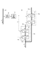
本発明の実施形態における電流遮断装置10の構成例を図1に示す。また、図1に示した電流遮断装置10に含まれる第2の電流遮断回路13の構成例を図2に示す。
A configuration example of a current interrupt
図1に示した電流遮断装置10は、例えば車両に搭載され、車両上の各種電装品の間を電気接続するために配索されるワイヤハーネスの一部分に挿入した状態で使用される。すなわち、図1に示した例では、電流遮断装置10の上流側の端子10aが上流側電線22を経由してオルタネータ(発電機)21の正極側電極21aと接続され、下流側の端子10bが下流側電線23を経由して負荷24およびバッテリー25の正極側電極と接続されている。オルタネータ21、負荷24、およびバッテリー25の負極側電極は、それぞれアースに接続されている。
The current interrupting
つまり、電流遮断装置10の端子10aと端子10bとの間は通常は電気的に導通状態であるが、過電流が流れると回路を遮断し、オルタネータ21と負荷24およびバッテリー25との間で電流が流れなくなるように制御する。電流遮断装置10、上流側電線22、および下流側電線23はワイヤハーネスの一部分として構成される。
In other words, the
図1に示した構成においては、電流遮断装置10は、分流部11、第1の電流遮断回路12、第2の電流遮断回路13、および合流部14を有している。オルタネータ21から上流側電線22を通り端子10aに向かって流れる電流i1は、分流部11で流路15、および流路16の2つの経路に分流する。流路15の電流i2は第1の電流遮断回路12を通過する経路を通り、流路16の電流i3は第2の電流遮断回路13を通過する経路を通る。また、流路15の電流i2と、流路16の電流i3は、合流部14で合流して端子10bから負荷24側に流れる。
In the configuration shown in FIG. 1, the current interrupt
第1の電流遮断回路12は、機械的なヒュージブルリンク(fusible link)により構成されている。このヒュージブルリンクは、一般的な電線と同様の導電材料により構成されているが、その前後に接続される他の電線と比べて非常に細い導電体として形成されている。したがって、一般的なヒューズの場合と同様に、規定の大電流が流れた時にヒュージブルリンクが溶断して物理的に回路を遮断する。
The first
ヒュージブルリンクは、回路ショートなどの異常発生時に、ワイヤハーネスに過電流が流れると他の箇所よりも早く溶断し、ワイヤハーネスの異常発熱に起因する発煙や発火を防止することができる。また、発熱する箇所および溶断する箇所がヒュージブルリンクの部位のみに限定されるため、車両のメンテナンスや修理が容易になる。 The fusible link can be melted earlier than the other part when an overcurrent flows through the wire harness when an abnormality such as a circuit short circuit occurs, thereby preventing smoke and fire due to abnormal heat generation of the wire harness. Further, since the location where heat is generated and the location where fusing is limited to the fusible link location, vehicle maintenance and repair are facilitated.
一方、第2の電流遮断回路13は、半導体スイッチを用いて構成してある。また、図1および図2に示した例では、2つの半導体スイッチ回路13a、13bを並列に接続してある。また、半導体スイッチ回路13a、13bの各々は、直列に接続した2つのスイッチング素子17、18を備えている。
On the other hand, the second
スイッチング素子17および18は、Nチャネル型のパワーMOSFET(電界効果トランジスタ)であり、お互いの寄生ダイオードが反対極性になる状態で直列に接続してある。例えば、図2に示すように半導体スイッチ回路13aについては、スイッチング素子18のドレイン端子(D)を流路16aと接続し、スイッチング素子17のソース端子(S)とスイッチング素子18のソース端子(S)を互いに接続し、スイッチング素子17のドレイン端子(D)を流路16cと接続してある。これにより、通常と逆の極性の電圧が印加された場合でも、意図しない電流が流れたり半導体等が破壊されるのを防ぐことができる。
The switching
図1および図2に示すように、複数の半導体スイッチ回路13a、13bを並列に接続してある理由は、大きな電流の通過を許容するため、およびこの経路を通過する電流に対する抵抗値を調整するためである。なお、図1および図2に示した例では2つの半導体スイッチ回路13a、13bを並列に接続してあるが、状況に応じて3つ、またはそれ以上の数の半導体スイッチ回路を並列に接続する場合もある。
As shown in FIGS. 1 and 2, the reason why the plurality of
第2の電流遮断回路13は、図2に示すように、電流遮断制御部31および電流検出部32を備えている。電流検出部32は、例えば上流側電線22に流れる直流電流i1の電流値を検出することができる。電流遮断制御部31は、各半導体スイッチ回路13a、13b内のスイッチング素子17および18の制御入力であるゲート端子(G)をオンオフするための制御信号を出力する。
As shown in FIG. 2, the second
具体的には、正常な状況であれば、半導体スイッチ回路13a、13b内の各スイッチング素子17および18のドレイン−ソース間が導通するオン状態に制御し、電流検出部32が事前に定めた所定以上の過電流を検知した時には、半導体スイッチ回路13a、13b内の各スイッチング素子17および18のドレイン−ソース間が非導通になるオフ状態に制御する。
Specifically, in a normal state, the
<電流遮断装置10における特別な制御の説明>
本発明の実施形態では、図1に示した電流遮断装置10において、分流部11で分流して流路15側に流れる電流i2、および流路16側に流れる電流i3の比率が、少なくとも通常の使用状態において、事前に定めた規定値になるように制御する。例えば、(i2/i1)の比率、(i3/i1)の比率がいずれも50%になるように制御する。
<Description of Special Control in
In the embodiment of the present invention, in the current interrupting
実際には、第1の電流遮断回路12におけるヒュージブルリンクを主体とする電気抵抗と、第2の電流遮断回路13における電気抵抗との関係を相対的に調整することで、前記比率を特定できる。
Actually, the ratio can be specified by relatively adjusting the relationship between the electrical resistance mainly of the fusible link in the first
例えば、第1の電流遮断回路12におけるヒュージブルリンクを主体とする回路の電気抵抗値がR12、第2の電流遮断回路13の電気抵抗値がR13の場合に、「R12=R13」の関係を満たすように事前に調整されていれば、以下に示す状態になる。
i2=i3
i2/i1=50[%]
i3/i1=50[%]
For example, when the electrical resistance value of the circuit mainly including the fusible link in the first
i2 = i3
i2 / i1 = 50 [%]
i3 / i1 = 50 [%]
つまり、第1の電流遮断回路12内のヒュージブルリンクに流れる電流i2を、全体の電流(i1)の半分にすることができる。また、第2の電流遮断回路13に流れる電流i3も全体の電流(i1)の半分にすることができる。
That is, the current i2 flowing through the fusible link in the first
電気抵抗値R12については、ヒュージブルリンクを構成する導電体の材質、太さなどにより決まる。電気抵抗値R13については、スイッチング素子17、18のオン抵抗、半導体スイッチ回路13a、13bの並列接続数などにより決まる。したがって、「R12=R13」の関係を満たすように回路を設計することが可能である。
The electrical resistance value R12 is determined by the material, thickness, etc. of the conductor constituting the fusible link. The electrical resistance value R13 is determined by the ON resistance of the switching
次に、仕様および設計手順の具体例を説明する。
オルタネータ21の仕様の具体例として、ここでは定格最大電流が150[A]の場合を想定する。但し、瞬間的には前記定格最大電流よりも大きい電流が流れることを許容するものとする。したがって、この場合はオルタネータ21から上流側電線22に流れる電流i1が規定値の150[A]以上になった場合に、過電流とみなして通電を遮断する必要がある。
Next, specific examples of specifications and design procedures will be described.
As a specific example of the specification of the
この電流i1の規定値(150[A])に基づいて、電流遮断装置10を設計する。電流i1は、電流遮断装置10内では分流部11で、電流i2、およびi3に分流する。ここで、上記のようにi2/i1=50[%]、i3/i1=50[%]の条件を想定すると、電流i2の規定値は150[A]の半分の75[A]になる。また、電流i3の規定値も150[A]の半分の75[A]になる。
The current interrupting
一方、ヒュージブルリンクを使う場合には、溶断により回路が遮断された場合に部品を交換しない限り元の状態に復旧することができない。したがって、頻繁に溶断が生じるような事態を避け、しかもワイヤハーネスからの火災の発生を確実に防止できるように、ヒュージブルリンクの仕様を決定する必要がある。具体的には、規定値の2倍の電流が流れた時にヒュージブルリンクが溶断するように設計する。 On the other hand, when the fusible link is used, the original state cannot be restored unless the parts are replaced when the circuit is cut off by fusing. Therefore, it is necessary to determine the specifications of the fusible link so as to avoid a situation where the fusing frequently occurs and to surely prevent the occurrence of fire from the wire harness. Specifically, the fusible link is designed to blow when a current twice the specified value flows.
つまり、図1に示した電流遮断装置10の場合には、第1の電流遮断回路12のヒュージブルリンクに流れる電流i2の規定値が75[A]であるので、このヒュージブルリンクが溶断する電流の基準値は、前記規定値の2倍の150[A]に定める。つまり、遮断電流の定格値が150[A]のヒュージブルリンクを採用することに決定する。
In other words, in the case of the current interrupt
次に、i2/i1=50[%]、i3/i1=50[%]の条件を満たすように、第2の電流遮断回路13を設計する。つまり、電流i3が流れる流路16の抵抗値を代表する第2の電流遮断回路13の電気抵抗値が、第1の電流遮断回路12のヒュージブルリンクの抵抗値とほぼ同じになるように設計する。具体的には、スイッチング素子17、18として適切な特性の半導体デバイスを選定したり、並列に接続する半導体スイッチ回路13a、13bの回路数を調整する。
Next, the second
次に、上流側電線22および下流側電線23における導電体の断面積(mm2)を決定する。導電体の断面形状が円形の場合は断面積の代わりに電線径(直径)を規定してもよい。これらの電線の断面積を決める際には、第1の電流遮断回路12のヒュージブルリンクが正しく動作するようにマッチングを考慮する。つまり、大電流が流れた時に、確実にヒュージブルリンクの箇所で溶断が発生し、上流側電線22および下流側電線23の箇所で溶断や異常な発熱が生じないように設計する。
Next, the cross-sectional area (mm < 2 >) of the conductor in the upstream
実際には、ヒュージブルリンクの遮断電流の定格値と整合するように、上流側電線22および下流側電線23の断面積を決定する。上記の条件では、ヒュージブルリンクの遮断電流の定格値が150[A]であるので、これと整合するように、上流側電線22および下流側電線23の各々の断面積を30[mm2]に決定する。この断面積の数値は、計算式または一覧表を用いることにより、遮断電流の定格値に基づいて容易に特定できる。
Actually, the cross-sectional areas of the upstream
<構成が異なる複数種類の電流遮断装置の対比>
図1に示した電流遮断装置10の優位性を評価できるように、構成の異なる3種類の構成(構成A、構成B、構成C)の電流遮断装置について対比する。ここで、「構成A」の電流遮断装置は、図3に示すように、機械的なヒュージブルリンクだけを用いて構成した場合を想定している。また、「構成B」の電流遮断装置は、図1中の第2の電流遮断回路13のような半導体スイッチだけで構成し、ヒュージブルリンクを含まない場合を想定している。また、「構成C」は、図1に示した本発明の電流遮断装置10に相当する。
<Comparison of multiple types of current interrupting devices with different configurations>
In order to evaluate the superiority of the current interrupting
ここで、「構成A」、「構成B」、「構成C」のいずれについても、電流遮断装置全体の遮断電流の定格値が150[A]である場合を想定して設計した電流遮断装置を比較する。「構成A」、「構成B」、「構成C」の各々の電流遮断装置について、上流側電線22および下流側電線23の電線径(断面積[mm2])と、外形サイズと、総合的評価との一覧を次の表1に示す。「外形サイズ」については、「構成B」の寸法を100とした場合の相対値を示してある。
Here, for any of “Configuration A”, “Configuration B”, and “Configuration C”, a current interrupting device designed on the assumption that the rated value of the interrupting current of the entire current interrupting device is 150 [A]. Compare. For each of the current interrupting devices of “Configuration A”, “Configuration B”, and “Configuration C”, the wire diameter (cross-sectional area [mm 2 ]) of the

「構成A」の電流遮断装置の場合には、ヒュージブルリンクの遮断電流の定格値が300[A](電流i1の定格値の2倍)になるため、このヒュージブルリンクの仕様とマッチングさせるために、上流側電線22および下流側電線23の電線径(断面積)が表1に示すように60になる。
In the case of the current interrupting device of “Configuration A”, the rated value of the breaking current of the fusible link is 300 [A] (twice the rated value of the current i1). For this reason, the wire diameters (cross-sectional areas) of the upstream
「構成B」の電流遮断装置の場合には、ヒュージブルリンクを用いないので、半導体スイッチを用いて遮断する電流i1の定格値(150[A])に合わせて、上流側電線22および下流側電線23の電線径を決定する。したがって、表1に示すように電線径(断面積)が30になる。
In the case of the current interrupting device of “Configuration B”, since the fusible link is not used, the upstream side
「構成C」の電流遮断装置の場合には、ヒュージブルリンクの遮断電流の定格値が150[A](電流i2の定格値の2倍)になるため、このヒュージブルリンクの仕様とマッチングさせるために、上流側電線22および下流側電線23の電線径(断面積)が表1に示すように30になる。また、第2の電流遮断回路13の遮断電流は75[A]であるので、全体の電流i1の定格値(150[A])を考慮しても、電線径(断面積)は30のままで構わない。
In the case of the current interrupting device of “Configuration C”, the rated value of the breaking current of the fusible link is 150 [A] (twice the rated value of the current i2). For this reason, the wire diameters (cross-sectional areas) of the upstream
一方、外形サイズについては、ヒュージブルリンクだけを用いる「構成A」の場合が最も小さい値(20)になる。「構成C」の電流遮断装置の場合には、ヒュージブルリンクの他に第2の電流遮断回路13も搭載する必要があるため、外形サイズは、「構成A」と比べて少し大きい値(30)になる。一方、「構成B」の電流遮断装置の場合には、大電流(150[A])の通電および遮断を可能にするために、多数の半導体スイッチを並列に接続しなければならず、結果的に外形サイズが非常に大きい値(100)になってしまうことが判明した。
On the other hand, the outer size is the smallest value (20) in the case of “Configuration A” using only the fusible link. In the case of the current interrupting device of “Configuration C”, it is necessary to mount the second current interrupting
したがって、表1に示したように、上流側電線22および下流側電線23の電線径と、「外形サイズ」とを総合的に評価すると、「構成C」、すなわち本発明の電流遮断装置10の顕著な優位性が認められる。すなわち、「構成A」の場合は、上流側電線22および下流側電線23の電線径が大きすぎるため、ワイヤハーネスの配索作業性や重量の点で大きく劣ることになる。また、「構成B」の場合は、搭載する半導体スイッチの個数が増えるだけでなく、十分な放熱空間を確保しなければならないため電流遮断装置自体が大型化し、ワイヤハーネスを配索するために余分な空間の確保が必要になる。
Therefore, as shown in Table 1, when the wire diameters of the upstream
<変形の可能性>
図2に示した第2の電流遮断回路13においては、電流検出部32が上流側電線22を流れる電流i1を検出しているが、その他の箇所、例えば下流側電線23の電流や、流路16の電流i3を検出しても良い。また、図2の例では複数の半導体スイッチ回路13a、13bを1つの電流遮断制御部31が共通の制御信号を用いてオンオフ制御しているが、半導体スイッチ回路毎に個別に制御しても良い。また、スイッチング素子17、18などのデバイス自体に電流検出機能や過電流遮断機能が内蔵されているような場合には、その機能を利用して電流遮断制御部31や電流検出部32を省略することもできる。
<Possibility of deformation>
In the second
ここで、上述した本発明に係る電流遮断装置及びワイヤハーネスの実施形態の特徴をそれぞれ以下[1]〜[5]に簡潔に纏めて列記する。
[1] 所定以上の電流に対して物理的に回路を遮断する第1の電流遮断回路(12)と、
少なくとも1つの半導体スイッチデバイスを有し、所定以上の電流に対して回路を遮断する第2の電流遮断回路(13)と、を備え、
前記第1の電流遮断回路(12)と前記第2の電流遮断回路(13)とが並列に接続され、
所定の状況下において、前記第1の電流遮断回路(12)に流れる電流(i2)と、前記第2の電流遮断回路(13)に流れる電流(i3)との比率が、予め定めた規定値になるように構成されている、
電流遮断装置。
Here, the features of the above-described embodiments of the current interrupting device and the wire harness according to the present invention are summarized and listed in the following [1] to [5], respectively.
[1] a first current cut-off circuit (12) that physically cuts the circuit against a predetermined current or more;
A second current interrupting circuit (13) having at least one semiconductor switch device and interrupting the circuit with respect to a predetermined current or more,
The first current cutoff circuit (12) and the second current cutoff circuit (13) are connected in parallel,
Under a predetermined condition, a ratio between a current (i2) flowing through the first current cutoff circuit (12) and a current (i3) flowing through the second current cutoff circuit (13) is a predetermined specified value. Configured to be,
Current interrupt device.
[2] 前記第1の電流遮断回路(12)が、車両上に搭載されるワイヤハーネスに用いられるヒュージブルリンクである、
上記[1]に記載の電流遮断装置。
[2] The first current interrupt circuit (12) is a fusible link used for a wire harness mounted on a vehicle.
The current interrupting device according to [1] above.
[3] 前記第2の電流遮断回路の電気抵抗値が、前記第1の電流遮断回路の電気抵抗値及び前記比率に基づいて決定される、
上記[1]又は[2]に記載の電流遮断装置。
[3] The electrical resistance value of the second current cutoff circuit is determined based on the electrical resistance value of the first current cutoff circuit and the ratio.
The current interrupting device according to the above [1] or [2].
[4] 前記第2の電流遮断回路は、複数組の半導体スイッチデバイス(半導体スイッチ回路13a、13b)が並列に接続された並列スイッチ回路により構成される、
上記[3]に記載の電流遮断装置。
[4] The second current cutoff circuit includes a parallel switch circuit in which a plurality of sets of semiconductor switch devices (
The current interrupting device according to the above [3].
[5] 上記[1]乃至[4]のいずれかに記載の電流遮断装置と、
車両に搭載された発電機と前記電流遮断装置とを接続する第1の電線(上流側電線22)と、
前記電流遮断装置と前記車両に搭載された負荷またはバッテリーと接続される第2の電線(下流側電線23)と、を備え、
前記第1の電線の導体の断面積及び前記前記第2の電線の導体の断面積が、前記第1の電流遮断回路における定格遮断電流に応じて決定される、
ワイヤハーネス。
[5] The current interrupting device according to any one of [1] to [4],
A first electric wire (upstream electric wire 22) connecting the generator mounted on the vehicle and the current interrupting device;
A second electric wire (downstream electric wire 23) connected to the current interrupt device and a load or battery mounted on the vehicle,
The cross-sectional area of the conductor of the first electric wire and the cross-sectional area of the conductor of the second electric wire are determined according to a rated breaking current in the first current breaking circuit;
Wire harness.
10 電流遮断装置
10a,10b 端子
11 分流部
12 第1の電流遮断回路
13 第2の電流遮断回路
13a,13b 半導体スイッチ回路
14 合流部
15,16,16a,16b 流路
17,18 スイッチング素子
21 オルタネータ
22 上流側電線
23 下流側電線
24 負荷
25 バッテリー
31 電流遮断制御部
32 電流検出部
DESCRIPTION OF
Claims (5)
少なくとも1つの半導体スイッチデバイスを有し、所定以上の電流に対して回路を遮断する第2の電流遮断回路と、を備え、
前記第1の電流遮断回路と前記第2の電流遮断回路とが並列に接続され、
所定の状況下において、前記第1の電流遮断回路に流れる電流と、前記第2の電流遮断回路に流れる電流との比率が、予め定めた規定値になるように構成されている、
電流遮断装置。 A first current cut-off circuit that physically cuts off the circuit with respect to a predetermined current or more;
A second current interrupting circuit having at least one semiconductor switch device and interrupting the circuit with respect to a predetermined current or more,
The first current cutoff circuit and the second current cutoff circuit are connected in parallel;
Under a predetermined condition, the ratio of the current flowing through the first current cutoff circuit and the current flowing through the second current cutoff circuit is configured to be a predetermined specified value.
Current interrupt device.
請求項1に記載の電流遮断装置。 The first current cutoff circuit is a fusible link used for a wire harness mounted on a vehicle.
The current interrupting device according to claim 1.
請求項1又は請求項2に記載の電流遮断装置。 The electrical resistance value of the second current interrupt circuit is determined based on the electrical resistance value of the first current interrupt circuit and the ratio.
The current interrupting device according to claim 1 or 2.
請求項1乃至請求項3のいずれか1項に記載の電流遮断装置。 The second current cutoff circuit is constituted by a parallel switch circuit in which a plurality of sets of semiconductor switch devices are connected in parallel.
The current interruption device according to any one of claims 1 to 3.
車両に搭載された発電機と前記電流遮断装置とを接続する第1の電線と、
前記電流遮断装置と前記車両に搭載された負荷またはバッテリーと接続される第2の電線と、を備え、
前記第1の電線の導体の断面積及び前記前記第2の電線の導体の断面積が、前記第1の電流遮断回路における定格遮断電流に応じて決定される、
ワイヤハーネス。 The current interrupting device according to any one of claims 1 to 4,
A first electric wire connecting a generator mounted on a vehicle and the current interrupting device;
A second electric wire connected to the current interrupting device and a load or battery mounted on the vehicle,
The cross-sectional area of the conductor of the first electric wire and the cross-sectional area of the conductor of the second electric wire are determined according to a rated breaking current in the first current breaking circuit;
Wire harness.
Priority Applications (5)
| Application Number | Priority Date | Filing Date | Title |
|---|---|---|---|
| JP2016019976A JP6255429B2 (en) | 2016-02-04 | 2016-02-04 | Current interrupt device and wire harness |
| PCT/JP2017/003494 WO2017135269A1 (en) | 2016-02-04 | 2017-01-31 | Current cut-off device, and wire harness |
| CN201780009962.5A CN108604791A (en) | 2016-02-04 | 2017-01-31 | Failure of current device and harness |
| DE112017000661.9T DE112017000661T5 (en) | 2016-02-04 | 2017-01-31 | Power shut-off device and wiring harness |
| US16/038,477 US20180323601A1 (en) | 2016-02-04 | 2018-07-18 | Current cut-off device, and wire harness |
Applications Claiming Priority (1)
| Application Number | Priority Date | Filing Date | Title |
|---|---|---|---|
| JP2016019976A JP6255429B2 (en) | 2016-02-04 | 2016-02-04 | Current interrupt device and wire harness |
Publications (2)
| Publication Number | Publication Date |
|---|---|
| JP2017139902A true JP2017139902A (en) | 2017-08-10 |
| JP6255429B2 JP6255429B2 (en) | 2017-12-27 |
Family
ID=59499872
Family Applications (1)
| Application Number | Title | Priority Date | Filing Date |
|---|---|---|---|
| JP2016019976A Active JP6255429B2 (en) | 2016-02-04 | 2016-02-04 | Current interrupt device and wire harness |
Country Status (5)
| Country | Link |
|---|---|
| US (1) | US20180323601A1 (en) |
| JP (1) | JP6255429B2 (en) |
| CN (1) | CN108604791A (en) |
| DE (1) | DE112017000661T5 (en) |
| WO (1) | WO2017135269A1 (en) |
Cited By (7)
| Publication number | Priority date | Publication date | Assignee | Title |
|---|---|---|---|---|
| WO2019197459A3 (en) * | 2018-04-10 | 2020-02-06 | Eaton Intelligent Power Limited | System, method, and apparatus for power distribution in an electric mobile application using a combined breaker and relay |
| US11050241B2 (en) | 2017-11-08 | 2021-06-29 | Eaton Intelligent Power Limited | Active current injection through a fuse for an electric mobile application |
| US11052784B2 (en) | 2017-11-08 | 2021-07-06 | Eaton Intelligent Power Limited | Power distribution unit and fuse management for an electric mobile application |
| US11108225B2 (en) | 2017-11-08 | 2021-08-31 | Eaton Intelligent Power Limited | System, method, and apparatus for power distribution in an electric mobile application using a combined breaker and relay |
| US11368031B2 (en) | 2017-11-08 | 2022-06-21 | Eaton Intelligent Power Limited | Power distribution and circuit protection for a mobile application having a high efficiency inverter |
| US11670937B2 (en) | 2019-02-22 | 2023-06-06 | Eaton Intelligent Power Limited | Coolant connector having a chamfered lip and fir tree axially aligned with at least one o-ring |
| JP7453228B2 (en) | 2018-11-27 | 2024-03-19 | ルノー エス.ア.エス. | Power system installed in vehicle |
Families Citing this family (2)
| Publication number | Priority date | Publication date | Assignee | Title |
|---|---|---|---|---|
| DE102020107695A1 (en) | 2020-03-19 | 2021-09-23 | Audi Aktiengesellschaft | Procedure for configuring an on-board network |
| DE102020213747A1 (en) | 2020-11-02 | 2022-05-05 | Robert Bosch Gesellschaft mit beschränkter Haftung | Method for driving at least two semiconductor devices connected in parallel to separate an electrical current that is above a predefined threshold value |
Citations (4)
| Publication number | Priority date | Publication date | Assignee | Title |
|---|---|---|---|---|
| JPH04230916A (en) * | 1990-04-14 | 1992-08-19 | Sachsenwerk Ag | Load switch or load-cutting switch and switching circuit device having fuse |
| JPH11234894A (en) * | 1998-02-12 | 1999-08-27 | Hitachi Ltd | Circuit breaker employing semiconductor device |
| JP2007502005A (en) * | 2003-08-08 | 2007-02-01 | デルファイ・テクノロジーズ・インコーポレーテッド | Circuit breaker |
| JP2014239293A (en) * | 2013-06-06 | 2014-12-18 | 株式会社オートネットワーク技術研究所 | Power supply control device |
Family Cites Families (11)
| Publication number | Priority date | Publication date | Assignee | Title |
|---|---|---|---|---|
| US5576612A (en) * | 1995-01-23 | 1996-11-19 | Motorola, Inc. | Ultrafast rechargeable battery pack and method of charging same |
| US6693011B2 (en) * | 2001-10-02 | 2004-02-17 | Fraunhofer-Gesellschaft Zur Foerderung Der Angewandten Forschung E.V. | Power MOS element and method for producing the same |
| JP2011101512A (en) | 2009-11-06 | 2011-05-19 | Toko Inc | Input protection circuit used for usb connection apparatus |
| US8006789B2 (en) * | 2010-09-02 | 2011-08-30 | Everette Energy, LLC | Electric vehicle with switched reluctance motor power plant |
| KR101233048B1 (en) * | 2011-07-22 | 2013-02-13 | 엘에스산전 주식회사 | Fault current limiter |
| JP2013192392A (en) | 2012-03-14 | 2013-09-26 | Fuji Electric Co Ltd | Inverter device |
| JP2014015133A (en) | 2012-07-09 | 2014-01-30 | Auto Network Gijutsu Kenkyusho:Kk | Power source device for vehicle |
| JP6124630B2 (en) | 2013-03-15 | 2017-05-10 | 矢崎総業株式会社 | Vehicle power shut-off device |
| JP2015002100A (en) * | 2013-06-17 | 2015-01-05 | 日立金属株式会社 | Coaxial cable |
| JP2015011933A (en) | 2013-07-01 | 2015-01-19 | 日本電信電話株式会社 | Dc breaker |
| JP6314845B2 (en) * | 2015-01-08 | 2018-04-25 | 株式会社オートネットワーク技術研究所 | Electrical junction box |
-
2016
- 2016-02-04 JP JP2016019976A patent/JP6255429B2/en active Active
-
2017
- 2017-01-31 WO PCT/JP2017/003494 patent/WO2017135269A1/en active Application Filing
- 2017-01-31 CN CN201780009962.5A patent/CN108604791A/en active Pending
- 2017-01-31 DE DE112017000661.9T patent/DE112017000661T5/en not_active Ceased
-
2018
- 2018-07-18 US US16/038,477 patent/US20180323601A1/en not_active Abandoned
Patent Citations (4)
| Publication number | Priority date | Publication date | Assignee | Title |
|---|---|---|---|---|
| JPH04230916A (en) * | 1990-04-14 | 1992-08-19 | Sachsenwerk Ag | Load switch or load-cutting switch and switching circuit device having fuse |
| JPH11234894A (en) * | 1998-02-12 | 1999-08-27 | Hitachi Ltd | Circuit breaker employing semiconductor device |
| JP2007502005A (en) * | 2003-08-08 | 2007-02-01 | デルファイ・テクノロジーズ・インコーポレーテッド | Circuit breaker |
| JP2014239293A (en) * | 2013-06-06 | 2014-12-18 | 株式会社オートネットワーク技術研究所 | Power supply control device |
Cited By (34)
| Publication number | Priority date | Publication date | Assignee | Title |
|---|---|---|---|---|
| US11128125B2 (en) | 2017-11-08 | 2021-09-21 | Eaton Intelligent Power Limited | System, method, and apparatus for power distribution in an electric mobile application using a combined breaker and relay |
| US11081875B2 (en) | 2017-11-08 | 2021-08-03 | Eaton Intelligent Power Limited | System, method and apparatus for power distribution in an electric mobile application using a combined breaker and relay |
| US11052784B2 (en) | 2017-11-08 | 2021-07-06 | Eaton Intelligent Power Limited | Power distribution unit and fuse management for an electric mobile application |
| US11063421B2 (en) | 2017-11-08 | 2021-07-13 | Eaton Intelligent Power Limited | Integrated coolant channels for component cooling in electric mobile applications |
| US11845358B2 (en) | 2017-11-08 | 2023-12-19 | Eaton Intelligent Power Limited | Fuse management for an electric mobile application |
| US11075514B2 (en) | 2017-11-08 | 2021-07-27 | Eaton Intelligent Power Limited | System, method, and apparatus for power distribution in an electric mobile application during run time using configurable electrical interface ports |
| US11081874B2 (en) | 2017-11-08 | 2021-08-03 | Eaton Intelligent Power Limited | System, method, and apparatus for power distribution in an electric mobile application using a combined breaker and relay |
| US11152781B2 (en) | 2017-11-08 | 2021-10-19 | Eaton Intelligent Power Limited | System, method, and apparatus for power distribution in an electric mobile application using a combined breaker and relay |
| US11088533B2 (en) | 2017-11-08 | 2021-08-10 | Eaton Intelligent Power Limited | Active current injection through a fuse for an electric mobile application |
| US11159008B2 (en) | 2017-11-08 | 2021-10-26 | Eaton Intelligent Power Limited | System, method, and apparatus for power distribution in an electric mobile application using a combined breaker and relay |
| US11095115B2 (en) | 2017-11-08 | 2021-08-17 | Eaton Intelligent Power Limited | System, method, and apparatus for power distribution in an electric mobile application using a combined breaker and relay |
| US11101639B2 (en) | 2017-11-08 | 2021-08-24 | Eaton Intelligent Power Limited | Inverter with quick connect cooling coupling for an electric mobile application |
| US11108225B2 (en) | 2017-11-08 | 2021-08-31 | Eaton Intelligent Power Limited | System, method, and apparatus for power distribution in an electric mobile application using a combined breaker and relay |
| US11114840B2 (en) | 2017-11-08 | 2021-09-07 | Eaton Intelligent Power Limited | System, method, and apparatus for power distribution in an electric mobile application using a combined breaker and relay |
| US11121540B2 (en) | 2017-11-08 | 2021-09-14 | Eaton Intelligent Power Limited | System, method, and apparatus for multi-port power converter and inverter assembly |
| US11128124B2 (en) | 2017-11-08 | 2021-09-21 | Eaton Intelligent Power Limited | System, method, and apparatus for power distribution in an electric mobile application during run time using configurable electrical interface ports |
| US11070049B2 (en) | 2017-11-08 | 2021-07-20 | Eaton Intelligent Power Limited | System, method, and apparatus for power distribution in an electric mobile application using a combined breaker and relay |
| US11050241B2 (en) | 2017-11-08 | 2021-06-29 | Eaton Intelligent Power Limited | Active current injection through a fuse for an electric mobile application |
| US11095116B2 (en) | 2017-11-08 | 2021-08-17 | Eaton Intelligent Power Limited | Fuse life management in an electric mobile application |
| US11183833B2 (en) | 2017-11-08 | 2021-11-23 | Eaton Intelligent Power Limited | System, method, and apparatus for power distribution in an electric mobile application during run time using configurable electrical interface ports |
| US11368031B2 (en) | 2017-11-08 | 2022-06-21 | Eaton Intelligent Power Limited | Power distribution and circuit protection for a mobile application having a high efficiency inverter |
| US11370324B2 (en) | 2017-11-08 | 2022-06-28 | Eaton Intelligent Power Limited | Fuse and contactor management for an electric mobile application |
| US11658477B2 (en) | 2017-11-08 | 2023-05-23 | Eaton Intelligent Power Limited | System, method, and apparatus for multi-port power converter and inverter assembly |
| US11660977B2 (en) | 2017-11-08 | 2023-05-30 | Eaton Intelligent Power Limited | Active current injection through a fuse for an electric mobile application |
| US11660978B2 (en) | 2017-11-08 | 2023-05-30 | Eaton Intelligent Power Limited | Current control in a power distribution unit using a contactor |
| US11660976B2 (en) | 2017-11-08 | 2023-05-30 | Eaton Intelligent Power Limited | Fuse management for an electric mobile application |
| US11664649B2 (en) | 2017-11-08 | 2023-05-30 | Eaton Intelligent Power Limited | Power distribution unit with a configurable offset voltage for fuse current determination |
| US11757277B2 (en) | 2017-11-08 | 2023-09-12 | Eaton Intelligent Power Limited | System, method, and apparatus for current control in a power distribution unit using a solid state switch |
| US11738664B2 (en) | 2017-11-08 | 2023-08-29 | Eaton Intelligent Power Limited | Fuse and contactor with active current injection |
| WO2019197459A3 (en) * | 2018-04-10 | 2020-02-06 | Eaton Intelligent Power Limited | System, method, and apparatus for power distribution in an electric mobile application using a combined breaker and relay |
| JP7453228B2 (en) | 2018-11-27 | 2024-03-19 | ルノー エス.ア.エス. | Power system installed in vehicle |
| US11689010B2 (en) | 2019-02-22 | 2023-06-27 | Eaton Intelligent Power Limited | Coolant fitting promoting turbulent flow |
| US11682895B2 (en) | 2019-02-22 | 2023-06-20 | Eaton Intelligent Power Limited | Inverter assembly with integrated coolant coupling port |
| US11670937B2 (en) | 2019-02-22 | 2023-06-06 | Eaton Intelligent Power Limited | Coolant connector having a chamfered lip and fir tree axially aligned with at least one o-ring |
Also Published As
| Publication number | Publication date |
|---|---|
| US20180323601A1 (en) | 2018-11-08 |
| JP6255429B2 (en) | 2017-12-27 |
| WO2017135269A1 (en) | 2017-08-10 |
| DE112017000661T5 (en) | 2018-10-31 |
| CN108604791A (en) | 2018-09-28 |
Similar Documents
| Publication | Publication Date | Title |
|---|---|---|
| JP6255429B2 (en) | Current interrupt device and wire harness | |
| US20090109590A1 (en) | Self-protected solid-state electrical switching device | |
| CN103166439A (en) | Intrinsically safe energy limiting circuit | |
| JP2014512789A (en) | Electrical equipment for short-circuit protection of three-phase loads in a three-phase system | |
| US11381072B2 (en) | Quick battery disconnect system for high current circuits | |
| US20170236674A1 (en) | Fuse for a device to be protected | |
| JP5683753B1 (en) | Robot controller protection circuit | |
| JP2021518100A (en) | Circuit breaker control module | |
| JP7264920B2 (en) | Multistage protection device for overcurrent and overvoltage protected transfer of electrical energy | |
| JP5189892B2 (en) | Surge protection device | |
| KR101622187B1 (en) | Fault current limiter | |
| US11201462B2 (en) | Fault-tolerant solid state power controller | |
| US7064448B2 (en) | Power controller with bond wire fuse | |
| JP2017139903A (en) | Current cutoff device | |
| JP5295635B2 (en) | Surge protection device | |
| JP5220561B2 (en) | Surge protection device | |
| JP2011010483A (en) | Current separator and current-breaking device | |
| US11749484B2 (en) | Circuit protector arc flash reduction system with parallel connected semiconductor switch | |
| JP2012217271A (en) | Power supply device and power supply method | |
| JP6883460B2 (en) | Current breaker and wire harness | |
| CN112602243A (en) | Multi-stage protection device for overcurrent and overvoltage protection type electric energy transmission | |
| JP6354212B2 (en) | Protection system for power supply circuit of electric propulsion device | |
| WO2020083393A1 (en) | Power supply over-temperature protection circuit, method and system | |
| JP2012253864A (en) | Breaking auxiliary device and power feeding system circuit breaker | |
| JP7018959B2 (en) | DC cutoff device |
Legal Events
| Date | Code | Title | Description |
|---|---|---|---|
| A131 | Notification of reasons for refusal |
Free format text: JAPANESE INTERMEDIATE CODE: A131 Effective date: 20170926 |
|
| A521 | Request for written amendment filed |
Free format text: JAPANESE INTERMEDIATE CODE: A523 Effective date: 20171017 |
|
| TRDD | Decision of grant or rejection written | ||
| A01 | Written decision to grant a patent or to grant a registration (utility model) |
Free format text: JAPANESE INTERMEDIATE CODE: A01 Effective date: 20171107 |
|
| A61 | First payment of annual fees (during grant procedure) |
Free format text: JAPANESE INTERMEDIATE CODE: A61 Effective date: 20171204 |
|
| R150 | Certificate of patent or registration of utility model |
Ref document number: 6255429 Country of ref document: JP Free format text: JAPANESE INTERMEDIATE CODE: R150 |
|
| R250 | Receipt of annual fees |
Free format text: JAPANESE INTERMEDIATE CODE: R250 |
|
| R250 | Receipt of annual fees |
Free format text: JAPANESE INTERMEDIATE CODE: R250 |
|
| R250 | Receipt of annual fees |
Free format text: JAPANESE INTERMEDIATE CODE: R250 |
|
| S531 | Written request for registration of change of domicile |
Free format text: JAPANESE INTERMEDIATE CODE: R313531 |
|
| R350 | Written notification of registration of transfer |
Free format text: JAPANESE INTERMEDIATE CODE: R350 |
|
| R250 | Receipt of annual fees |
Free format text: JAPANESE INTERMEDIATE CODE: R250 |