JP2017138327A - Full-frame, programmable hyperspectral imager - Google Patents
Full-frame, programmable hyperspectral imager Download PDFInfo
- Publication number
- JP2017138327A JP2017138327A JP2017075912A JP2017075912A JP2017138327A JP 2017138327 A JP2017138327 A JP 2017138327A JP 2017075912 A JP2017075912 A JP 2017075912A JP 2017075912 A JP2017075912 A JP 2017075912A JP 2017138327 A JP2017138327 A JP 2017138327A
- Authority
- JP
- Japan
- Prior art keywords
- image system
- array
- image
- light
- spectral
- Prior art date
- Legal status (The legal status is an assumption and is not a legal conclusion. Google has not performed a legal analysis and makes no representation as to the accuracy of the status listed.)
- Granted
Links
- 230000003595 spectral effect Effects 0.000 claims abstract description 92
- 230000003287 optical effect Effects 0.000 claims abstract description 59
- 238000012545 processing Methods 0.000 claims abstract description 10
- 238000001228 spectrum Methods 0.000 claims description 31
- 230000005540 biological transmission Effects 0.000 claims description 18
- 210000001747 pupil Anatomy 0.000 claims description 17
- 239000000126 substance Substances 0.000 claims description 9
- 238000003384 imaging method Methods 0.000 claims description 7
- 238000012986 modification Methods 0.000 claims description 5
- 230000004048 modification Effects 0.000 claims description 5
- 238000005516 engineering process Methods 0.000 claims description 2
- 239000007789 gas Substances 0.000 claims description 2
- 229910052500 inorganic mineral Inorganic materials 0.000 claims description 2
- 239000007788 liquid Substances 0.000 claims description 2
- 239000011707 mineral Substances 0.000 claims description 2
- 239000000203 mixture Substances 0.000 claims description 2
- 239000007787 solid Substances 0.000 claims description 2
- 230000005856 abnormality Effects 0.000 claims 1
- 230000003278 mimic effect Effects 0.000 claims 1
- 239000004973 liquid crystal related substance Substances 0.000 abstract description 3
- 230000003993 interaction Effects 0.000 abstract 1
- 238000003491 array Methods 0.000 description 24
- 239000006185 dispersion Substances 0.000 description 19
- 238000000701 chemical imaging Methods 0.000 description 7
- 238000010586 diagram Methods 0.000 description 7
- 230000009471 action Effects 0.000 description 4
- 238000012360 testing method Methods 0.000 description 4
- DGAQECJNVWCQMB-PUAWFVPOSA-M Ilexoside XXIX Chemical compound C[C@@H]1CC[C@@]2(CC[C@@]3(C(=CC[C@H]4[C@]3(CC[C@@H]5[C@@]4(CC[C@@H](C5(C)C)OS(=O)(=O)[O-])C)C)[C@@H]2[C@]1(C)O)C)C(=O)O[C@H]6[C@@H]([C@H]([C@@H]([C@H](O6)CO)O)O)O.[Na+] DGAQECJNVWCQMB-PUAWFVPOSA-M 0.000 description 3
- 238000012544 monitoring process Methods 0.000 description 3
- 239000011734 sodium Substances 0.000 description 3
- 229910052708 sodium Inorganic materials 0.000 description 3
- 230000001629 suppression Effects 0.000 description 3
- CURLTUGMZLYLDI-UHFFFAOYSA-N Carbon dioxide Chemical compound O=C=O CURLTUGMZLYLDI-UHFFFAOYSA-N 0.000 description 2
- 230000008901 benefit Effects 0.000 description 2
- 238000001514 detection method Methods 0.000 description 2
- 238000002059 diagnostic imaging Methods 0.000 description 2
- 238000001914 filtration Methods 0.000 description 2
- 238000004519 manufacturing process Methods 0.000 description 2
- VNWKTOKETHGBQD-UHFFFAOYSA-N methane Chemical compound C VNWKTOKETHGBQD-UHFFFAOYSA-N 0.000 description 2
- 238000000034 method Methods 0.000 description 2
- 230000001902 propagating effect Effects 0.000 description 2
- 238000012800 visualization Methods 0.000 description 2
- 238000012935 Averaging Methods 0.000 description 1
- UGFAIRIUMAVXCW-UHFFFAOYSA-N Carbon monoxide Chemical compound [O+]#[C-] UGFAIRIUMAVXCW-UHFFFAOYSA-N 0.000 description 1
- CBENFWSGALASAD-UHFFFAOYSA-N Ozone Chemical compound [O-][O+]=O CBENFWSGALASAD-UHFFFAOYSA-N 0.000 description 1
- 244000007853 Sarothamnus scoparius Species 0.000 description 1
- 238000010521 absorption reaction Methods 0.000 description 1
- 239000006227 byproduct Substances 0.000 description 1
- 229910002092 carbon dioxide Inorganic materials 0.000 description 1
- 239000001569 carbon dioxide Substances 0.000 description 1
- 229910002091 carbon monoxide Inorganic materials 0.000 description 1
- 230000008859 change Effects 0.000 description 1
- 238000004891 communication Methods 0.000 description 1
- 238000012937 correction Methods 0.000 description 1
- 230000008021 deposition Effects 0.000 description 1
- 238000013461 design Methods 0.000 description 1
- 238000011161 development Methods 0.000 description 1
- 239000003814 drug Substances 0.000 description 1
- 230000009977 dual effect Effects 0.000 description 1
- 230000000694 effects Effects 0.000 description 1
- 230000005670 electromagnetic radiation Effects 0.000 description 1
- 230000007613 environmental effect Effects 0.000 description 1
- 239000000463 material Substances 0.000 description 1
- QSHDDOUJBYECFT-UHFFFAOYSA-N mercury Chemical compound [Hg] QSHDDOUJBYECFT-UHFFFAOYSA-N 0.000 description 1
- 238000002493 microarray Methods 0.000 description 1
- 238000000059 patterning Methods 0.000 description 1
- 238000000206 photolithography Methods 0.000 description 1
- 230000008569 process Effects 0.000 description 1
- 239000000047 product Substances 0.000 description 1
- 238000011002 quantification Methods 0.000 description 1
- 238000005316 response function Methods 0.000 description 1
- 230000004043 responsiveness Effects 0.000 description 1
- 241000894007 species Species 0.000 description 1
- 238000010561 standard procedure Methods 0.000 description 1
- 238000006467 substitution reaction Methods 0.000 description 1
- 230000001052 transient effect Effects 0.000 description 1
Images


Classifications
-
- H—ELECTRICITY
- H04—ELECTRIC COMMUNICATION TECHNIQUE
- H04N—PICTORIAL COMMUNICATION, e.g. TELEVISION
- H04N23/00—Cameras or camera modules comprising electronic image sensors; Control thereof
- H04N23/10—Cameras or camera modules comprising electronic image sensors; Control thereof for generating image signals from different wavelengths
- H04N23/11—Cameras or camera modules comprising electronic image sensors; Control thereof for generating image signals from different wavelengths for generating image signals from visible and infrared light wavelengths
-
- G—PHYSICS
- G01—MEASURING; TESTING
- G01J—MEASUREMENT OF INTENSITY, VELOCITY, SPECTRAL CONTENT, POLARISATION, PHASE OR PULSE CHARACTERISTICS OF INFRARED, VISIBLE OR ULTRAVIOLET LIGHT; COLORIMETRY; RADIATION PYROMETRY
- G01J3/00—Spectrometry; Spectrophotometry; Monochromators; Measuring colours
- G01J3/02—Details
- G01J3/0205—Optical elements not provided otherwise, e.g. optical manifolds, diffusers, windows
- G01J3/0208—Optical elements not provided otherwise, e.g. optical manifolds, diffusers, windows using focussing or collimating elements, e.g. lenses or mirrors; performing aberration correction
-
- G—PHYSICS
- G01—MEASURING; TESTING
- G01J—MEASUREMENT OF INTENSITY, VELOCITY, SPECTRAL CONTENT, POLARISATION, PHASE OR PULSE CHARACTERISTICS OF INFRARED, VISIBLE OR ULTRAVIOLET LIGHT; COLORIMETRY; RADIATION PYROMETRY
- G01J3/00—Spectrometry; Spectrophotometry; Monochromators; Measuring colours
- G01J3/02—Details
- G01J3/0205—Optical elements not provided otherwise, e.g. optical manifolds, diffusers, windows
- G01J3/0229—Optical elements not provided otherwise, e.g. optical manifolds, diffusers, windows using masks, aperture plates, spatial light modulators or spatial filters, e.g. reflective filters
-
- G—PHYSICS
- G01—MEASURING; TESTING
- G01J—MEASUREMENT OF INTENSITY, VELOCITY, SPECTRAL CONTENT, POLARISATION, PHASE OR PULSE CHARACTERISTICS OF INFRARED, VISIBLE OR ULTRAVIOLET LIGHT; COLORIMETRY; RADIATION PYROMETRY
- G01J3/00—Spectrometry; Spectrophotometry; Monochromators; Measuring colours
- G01J3/28—Investigating the spectrum
- G01J3/2823—Imaging spectrometer
Abstract
Description
連邦の権利に関する陳述
米国政府は、ロスアラモス国立研究所の動作のために、米国エネルギー省とロスアラモス国立セキュリティ、LLCとの間での契約No.DE−AC52−06NA25396に従った本発明の権利を有する。
Federal Rights Statement The United States government has signed a contract number between the US Department of Energy and Los Alamos National Security, LLC for the operation of the Los Alamos National Laboratory. The rights of the present invention according to DE-AC52-06NA25396 are reserved.
優先権主張
本出願は、表題「フルフレームのプログラム可能なハイパースペクトルイメージャ」の2011年9月30日に提出された米国仮特許出願第61/541789号の優先権を主張し、この参照により、本明細書中にその全体が組み込まれる。
This application claims priority to US Provisional Patent Application No. 61 / 541,789, filed Sep. 30, 2011, entitled “Full Frame Programmable Hyperspectral Imager”, and by this reference, The entirety of which is incorporated herein.
本発明は、概ね、分光及び空間的なイメージに関し、より具体的には、プログラム可能なマルチバンドスペクトルフィルタリング及び各画素が高分解能スペクトルを含むハイパースペクトルイメージングに関する。 The present invention relates generally to spectroscopic and spatial images, and more particularly to programmable multiband spectral filtering and hyperspectral imaging where each pixel contains a high resolution spectrum.
スペクトルイメージング、特に、各画素が高分解能スペクトルを含むハイパースペクトルイメージングは、増殖検出から環境モニタリング、惑星科学及び医用画像までの用途範囲において、遠隔検出、化学種の同定及び定量化のために貴重であることが証明された。各画素のスペクトル成分は、典型的には、研究されたスペクトル領域のスペクトルシグネチャを有する様々な化学物質又は関心のある物質の存在について分析される。現在実装されているように、ハイパースペクトルイメージングは、本質的に低速であり、通常、単一の画像を取得するために数秒を必要とする。これよりも速いタイムスケールで発生するモニター現象は、スペクトルの特異性を犠牲にすること(すなわち、高速カメラの前で単純なバンドパスフィルタのスペクトル成分を低減すること)又は空間的な情報を犠牲にすることのいずれかを必要とし、単にポイント(又はせいぜいライン)で分光計を向けることが必要とする。これらのオプションのどちらも、様々な理由で満足のいくものではない。 Spectral imaging, particularly hyperspectral imaging where each pixel contains a high resolution spectrum, is valuable for remote detection, species identification and quantification in applications ranging from growth detection to environmental monitoring, planetary science and medical imaging. Proven to be. The spectral components of each pixel are typically analyzed for the presence of various chemicals or substances of interest having a spectral signature of the studied spectral region. As currently implemented, hyperspectral imaging is inherently slow and typically requires several seconds to acquire a single image. Monitoring phenomena that occur at faster timescales sacrifice spectral specificity (ie, reduce the spectral content of simple bandpass filters in front of high-speed cameras) or sacrifice spatial information. Or simply point the spectrometer at a point (or at best a line). Neither of these options is satisfactory for various reasons.
一つの既存のプログラム可能なHSIシステムが、SPIE誌、Vol.7210、721007(2009年)のSteaven P.Loveによる「プログラム可能な整合フィルタ及びマイクロミラーアレイに基づくアダマール変換ハイパースペクトルイメージャ」に記載されており、その開示の全体及びその文献の教示が、この参照により、本明細書中に具体的に組み込まれる。残念ながら、Loveのプログラム可能なHSIは、MMAにわたってスペクトルパターンをスキャンするか、所望のスペクトル処理を有する完全な二次元空間画像を生成するために機器の照準の方向をスキャンする必要がある。このように、プログラム可能なスペクトルフィルタの開発は、ほぼすべての画像分光設計の特徴である分光及び空間の方向の相関関係によって絶望的な状況である。従って、改良されたフルフレームハイパースペクトルイメージ装置及び/又はシステムが必要とされている。以下に詳細に説明したように、本発明の実施形態は、スペクトルデータが適切に空間的データに関連付けられるスペクトル/空間的情報を生じるために外部の押しほうきスキャン又はマイクロミラーアレイ上のイメージのスキャンのいずれかが必要なしにフルフレームハイパースペクトルイメージを得るための装置を提供することによって従来技術の欠点および限界を克服する。 One existing programmable HSI system is described in SPIE magazine, Vol. 7210, 721007 (2009) Steaven P.M. Love's “Hadamard Transform Hyperspectral Imager Based on Programmable Matched Filters and Micromirror Arrays”, the entire disclosure of which and the teachings of that document are specifically incorporated herein by this reference. It is. Unfortunately, Love's programmable HSI needs to scan the spectral pattern across the MMA or scan the direction of the instrument's aim to produce a complete two-dimensional spatial image with the desired spectral processing. Thus, the development of programmable spectral filters is a desperate situation due to the correlation between the spectral and spatial directions that are characteristic of almost all image spectral designs. Accordingly, there is a need for an improved full frame hyperspectral imaging device and / or system. As described in detail below, embodiments of the present invention provide an external push broom scan or scan of an image on a micromirror array to produce spectral / spatial information where the spectral data is appropriately associated with the spatial data. It overcomes the disadvantages and limitations of the prior art by providing an apparatus for obtaining full frame hyperspectral images without the need for any of the above.
本発明の好ましい実施形態は、入射光を受光すると共に、イメージ面を有する第1の予め決められた位置で実質的に空間的に不変の入射角度を画定する空間的に不変の光伝播を含むイメージを生じる、最初の光学サブシステムと、実質的に空間的に不変の入射角度でのイメージを受信すると共に波長分散された光を生成するために予め決められた位置に配置される分散要素と、波長分散された光を受光すると共に、スペクトル面の少なくとも一つの次元において実質的に予め決められた波長の全ての光がスペクトル面内の実質的に同じ位置に向くように第2の予め決められた位置で空間的に分散されたスペクトルを生成する、第2の光学サブシステムと、を含むことができる。好ましい装置は、さらに、第2の予め決められた位置に配置されると共に、分散要素に光学的に結合された選択要素を含むことができ、選択要素は、スペクトル的に修正された光を生成するためにスペクトル面の一つ以上の位置で光の振幅をプログラム可能に変調するように構成されており、好ましい装置は、さらに、選択要素からスペクトル的に修正された光を受光する検出器を含むことができる。後述するように、好ましくは、スペクトル的に修正された光は、スペクトル成分が一つ以上のスペクトル帯域における選択要素によって修正される入射光のイメージ画像を含み、さらに好ましくは、そのようなスペクトルの修正は、イメージ画像の実質的に全ての位置において実質的に同一である。 Preferred embodiments of the present invention include spatially invariant light propagation that receives incident light and defines a substantially spatially invariant incident angle at a first predetermined position having an image plane. An initial optical subsystem that produces an image, and a dispersive element disposed at a predetermined location to receive the image at a substantially spatially invariant angle of incidence and to produce chromatically dispersed light Receiving a wavelength-dispersed light and second pre-determining so that all light of a pre-determined wavelength in at least one dimension of the spectral plane is directed to substantially the same position in the spectral plane. And a second optical subsystem that generates a spatially dispersed spectrum at the determined location. The preferred apparatus can further include a selection element disposed at the second predetermined location and optically coupled to the dispersive element, wherein the selection element generates spectrally modified light. The device is configured to programmably modulate the amplitude of light at one or more locations in the spectral plane, and the preferred apparatus further includes a detector that receives the spectrally modified light from the selected element. Can be included. As will be described below, preferably the spectrally modified light comprises an image of incident light whose spectral components are modified by selected elements in one or more spectral bands, and more preferably such spectral The correction is substantially the same in substantially all positions of the image.
本発明の実施形態の有益性及び利点は、全体の二次元イメージ上で波長がずれないで、完全な空間フレームマイクロミラーアレイに基づくスペクトル処理を実行するための装置を提供するが、これに限定されず、スペクトルイメージは、スキャンされないで、利用される検出器のみによって限定された速度で実行されることができる。現在のハイパースペクトルイメージデバイスに比べて、本発明の実施形態のための所与の領域の撮像時間は、数百の要因によって低減されることができる。 The benefits and advantages of embodiments of the present invention provide, but are not limited to, an apparatus for performing spectral processing based on a complete spatial frame micromirror array without wavelength shifting on the entire two-dimensional image. Rather, the spectral image is not scanned and can be performed at a limited speed only by the detector used. Compared to current hyperspectral image devices, the imaging time of a given region for embodiments of the present invention can be reduced by several hundred factors.
本発明の好ましい実施形態及びその変形の以下の説明は、図面及び一つ以上の図示の例示の構成及び/又は実装形態を参照して行われる。当業者は、以下の説明は、例示目的のためだけであり、本発明の範囲は以下の特許請求の範囲によって専ら定義されることを認識されるであろう。 The following description of preferred embodiments of the present invention and variations thereof is made with reference to the drawings and one or more illustrated exemplary configurations and / or implementations. Those skilled in the art will recognize that the following description is for illustrative purposes only, and that the scope of the present invention is defined solely by the following claims.
好適な装置
図1乃至図6を参照して以下に詳細に説明されるように、好適な実施形態の装置は、入射光を受光すると共に、イメージ面を有する第1の予め決められた位置で実質的に空間的に不変の入射角度を画定する空間的に不変の光伝播を含むイメージを生じる、最初の光学サブシステムと、実質的に空間的に不変の入射角度でのイメージを受信すると共に波長分散された光を生成するために予め決められた位置に配置される分散要素と、波長分散された光を受光すると共に、スペクトル面の少なくとも一つの次元において実質的に予め決められた波長の全ての光がスペクトル面内の実質的に同じ位置に向くように第2の予め決められた位置で空間的に分散されたスペクトルを生成する、第2の光学サブシステムと、を含むことができる。好適な実施形態の装置は、さらに、第2の予め決められた位置に配置されると共に、分散要素に光学的に結合された選択要素を含むことができ、選択要素は、スペクトル的に修正された光を生成するためにスペクトル面の一つ以上の位置で光の振幅をプログラム可能に変調するように構成されており、好適な実施形態の装置は、さらに、選択要素からスペクトル的に修正された光を受光する検出器を含むことができる。好ましくは、スペクトル的に修正された光は、スペクトル成分が一つ以上のスペクトル帯域における選択要素によって修正される入射光のイメージ画像を含み、さらに好ましくは、そのようなスペクトルの修正は、イメージ画像の実質的に全ての位置において実質的に同一である。
Preferred Apparatus As described in detail below with reference to FIGS. 1-6, the preferred embodiment apparatus receives incident light and is in a first predetermined position having an image plane. Receiving an image with a first optical subsystem and a substantially spatially invariant angle of incidence, resulting in an image that includes spatially invariant light propagation that defines a substantially spatially invariant angle of incidence; A dispersive element disposed at a predetermined position to generate chromatically dispersed light; and receiving the chromatically dispersed light and having a substantially predetermined wavelength in at least one dimension of the spectral plane. A second optical subsystem that generates a spatially dispersed spectrum at a second predetermined position such that all light is directed to substantially the same position in the spectral plane. . The apparatus of the preferred embodiment can further include a selection element disposed at the second predetermined location and optically coupled to the dispersive element, the selection element being spectrally modified. Configured to programmably modulate the amplitude of light at one or more locations in the spectral plane to generate additional light, and the apparatus of the preferred embodiment is further spectrally modified from the selected element. A detector that receives the reflected light can be included. Preferably, the spectrally modified light comprises an image image of incident light whose spectral content is modified by a selection element in one or more spectral bands, and more preferably such spectral modification is performed by an image image. Are substantially the same at substantially all positions.
当業者は、好適な実施形態の装置及びその変形例が、例えば、ディスプレイ、ユーザインタフェース、画像処理ハードウェア/ファームウェア/ソフトウェア、及び/又はその適当な組み合わせを含む、一つ以上の画像処理及び/又は視覚化コンポーネントと結合できることを理解するであろう。そのようなあらゆる画像処理及び/又は視覚化コンポーネントの組み合わせは、好適な実施形態の装置に対して、一体に又は分配することができる。好適な実施形態の他の変形例では、好適な実施形態の装置がリモートセンシングアップリケショーン及び/又は偵察航空機、無人機、衛星などのオンボードリモートセンシング車両に使用されることを可能にするように、一つ以上の通信モジュールが含まれることができる。 One skilled in the art will recognize that the devices of the preferred embodiments and variations thereof include one or more image processing and / or modifications including, for example, a display, a user interface, image processing hardware / firmware / software, and / or appropriate combinations thereof. Or it will be understood that it can be combined with a visualization component. Any such combination of image processing and / or visualization components can be integrated or distributed to the apparatus of the preferred embodiment. In another variation of the preferred embodiment, to allow the device of the preferred embodiment to be used in remote sensing appliqués and / or onboard remote sensing vehicles such as reconnaissance aircraft, drones, satellites, etc. One or more communication modules may be included.
好適な実施形態の装置の態様は、全てのイメージ点から発する光が、分散次元において実質的に同じ入射角でスペクトル分散要素に当たるのを確実にするために使用される戦略に従って変化させることができる。好適な実施形態の第1の変形は、必要な方向に光を向けるように及び他の方向に伝搬する光線を拒絶するように、組み合わせて配置された、マイクロレンズアレイ、開口アレイ、マイクロルーバーアレイ及び毛管アレイなどの微視的なアレイを利用することができる。好適な実施形態の第2の変形は、従来の巨視的な光学系を利用し、従来の巨視的な光学系を利用し、分散要素の初期イメージに対する画像空間においてテレセントリックである構成で初期イメージ光学系及び入射ひとみに配置することにより、所望の状態を達成することができる。光学分野の当業者は、光学要素の複数の組み合わせ及び置換があり、微視的及び巨視的の双方が、装置の具体的に図示された好適実施形態において以下に記載された所望の光学条件を達成することができることを理解されるであろう。 The apparatus aspects of the preferred embodiments can be varied according to the strategy used to ensure that light emanating from all image points strikes the spectral dispersion element at substantially the same angle of incidence in the dispersion dimension. . The first variant of the preferred embodiment is a microlens array, aperture array, microlouver array, arranged in combination to direct light in the required direction and reject light propagating in other directions And microscopic arrays such as capillary arrays can be utilized. A second variant of the preferred embodiment utilizes a conventional macroscopic optical system, utilizes a conventional macroscopic optical system, and provides an initial image optics in a configuration that is telecentric in the image space for the initial image of the dispersive element. By placing the system and the entrance pupil, the desired state can be achieved. Those skilled in the optical arts have multiple combinations and substitutions of optical elements, both microscopic and macroscopic, that meet the desired optical conditions described below in the specifically illustrated preferred embodiment of the apparatus. It will be understood that this can be achieved.
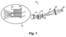
図1に示されるように、第1の好適な装置10において、最初のイメージ光学系12からの光は、第1光学アッセンブリ14でイメージを形成するために焦点に合わせられる。好ましくは、第1光学アッセンブリ14は、薄い並列なスタック14を含むことができ、
その表面は、好ましくは、光を吸収するために黒化され、そして、光がそれらの間を通過することができるように離間される。第1光学アッセンブリ14は、マイクロルーバーアレイ24を含むことができ、マイクロルーバーアレイ24は、好ましくは、所望の方向に移動する光線だけを選択して送信すると共に他の全ての光線を吸収するように機能する。任意の光線の所望の方向は、スペクトル分散の面に横たわるその伝播ベクトルの構成要素がイメージ内の場所に関係なく全ての光線に対して同じであるように選択される。伝播ベクトルの直交成分は、この要素がその後のスペクトル分散に影響しないように、任意の値をとるために、マイクロルーバーアレイ24によって許容される。従って、マイクロルーバーアレイ24によって選択された光線は、好ましくは、そのスペクトル成分に光を分散する透過格子26に当たる。図1に示されるように、集束光学系16は、スペクトルに分散された光を収集し、明確に画定されたスペクトル平面における空間的に分散したスペクトルにその光を焦点に合わせる。マイクロルーバーアレイ24の作用のために、各波長の光は、元のイメージに光が配向されるに関わらず、スペクトル平面内の単一の独特的に配置されたラインに焦点を当てられる。アドレス可能な空間光変調器18、好適な装置10のこの実装では、マイクロミラーアレイ18は、このスペクトル平面に配置される。マイクロミラーアレイ18は、好ましくは、任意の所望の波長帯域に向ける又は帯域をオンまたはオフに設定する、及び二次元イメージ全体を通じて同じ波長のためのそのようにするように機能する。図1に示されるように、最終のイメージ光学系20は、好ましくは、マイクロミラーアレイ18によって通過された波長帯域の光を収集し、これらの波長成分を再結合し、光を、検出器アレイ22で最終のスペクトル的にフィルタリングされたイメージに焦点を合わせることができる。検出器アレイ22は、被写体光特性及び条件に所望及び/又は最適なであるように、CCDアレイ又は任意の他の適当なアレイ又は光検出器を含むことができる。
As shown in FIG. 1, in a first preferred
The surfaces are preferably blackened to absorb light and are spaced so that light can pass between them. The first
図1に示された第1の好適な装置10では、イメージは、マイクロルーバーアレイ24の前方に位置し、最初の格子面は、ひとみでもイメージでもないが、マイクロルーバーアレイ24の作用のために、両方のいくつかの特徴を有する。好ましくは、マイクロミラーアレイ18は、空間的なイメージがマイクロミラーアレイ18上にないが、各波長がこの平面でラインに集束され、全ての空間的なイメージポイントからの寄与が所定の波長に対して同じラインに一緒に来るように、空間的なイメージが関係している限り、ひとみに配置される。すなわち、各空間的なイメージは、マイクロミラーアレイ面でスペクトルとして分散され、これらのスペクトルは、全ての空間的ポイントに対して一致した波長で重なる。最終的なイメージ光学系20は、好ましくは、後の格子光学系14の作用を逆転し、検出器アレイ20でスペクトル的に操作された白色光イメージを形成するために、各イメージポイントからの波長を再結合する。光学系14、20は、シンプルなレンズ、ミラー、多素子レンズ群、及び/又はそれらの適当な組み合わせにすることができる。上述のように、検出器アレイ20は、電荷結合素子(CCD)又は光検出器の任意の他の適切なタイプを含むことができる。
In the first
第1の好適な装置10の一変形例では、マイクロルーバーアレイ24は、スペクトル分散次元及び直行次元の双方で非視準線を拒絶する黒化毛管アレイで置換されることができる。第1の好適な装置10のこの変形例では、シーンのイメージは、透過格子26に存在するが、透過格子26に当たる光照射野は、毛細管から出てくる光線の平行な束から成るひとみ状である。全てのイメージポイントに対して同じ透過格子への入射角度に関し、回折角は波長の関数である。従って、透過格子26の直後に配置されたレンズ又は他の光学素子16は、元の空間位置に関わらず、スペクトルイメージ面における単一のラインに各波長をイメージする。次に、この面でのマイクロミラーアレイ18は、好ましくは、その波長が通過され、拒絶されるのを選択し、すべての画像ポイントに対して同じ方法でそれを行う。
In a variation of the first
図2に示されるように、本発明の装置10の第2の好適な実施形態は、同じ角度で透過格子34に全ての入射光を導くためのマイクロレンズアレイ30及び毛管アレイ32を含む。第2の好適な装置10は、さらに、その中にスペクトル情報を分析するための二つ以上の交差した偏光子38の間に配置された液晶デバイス(LCD)アレイ36を含むことができる。少なくとも一つの最終光学素子40は、好ましくは、波長を再結合し、検出器アレイ42で処理された白色光イメージを形成し、その後、イメージは、さらに分析されて、上述のように信号処理装置を用いて表示される。第2の好適な装置10の一変形例では、マイクロシャッタアレイ(図示せず)が、液晶デバイスアレイ36及び偏光子38の代わりに、又は液晶デバイスアレイ36及び偏光子38に加えて使用されることができる。図2に示されるように、第2の好適な装置10は、透過格子34を出る光を導く及び/又は集束するためのレンズ、ミラー、ミラーアレイなどの追加の光学素子44を含むことができる。
As shown in FIG. 2, a second preferred embodiment of the
図3に示されるように、装置の第3の好適な実施形態は、開口アレイ52、マイクロレンズアレイ54及び透過格子56を含むことができる。好ましくは、開口アレイ52及びマイクロレンズアレイ54は、前述の好適な実施形態の毛管アレイ又はマイクロルーバーアレイ24のように機能することができる。マイクロレンズアレイ54は、好ましくは、マイクロレンズアレイ54の前方のマイクロレンズの焦点距離に配置された整合開口アレイ52に結合される。好ましくは、方向画定開口及び小型レンズは、最初のイメージ面での各画素の位置に配置されることができ、それによって、上述のように全てのイメージポイントに対して同じである必要な方向に出射する光を向ける。透過格子56は、好ましくは、画素ごとに独立したマイクロ分光計の並列アレイを生じる。マイクロレンズアレイ54は、可視材及びIR材料の双方で任意の適当なタイプ又は構成にすることができる。実質的に任意の形状の適切な開口アレイ52は、開口の空間がマイクロレンズの開口と好ましく整合されるフォトリソグラフィ、レーザパターニング、または膜蒸着のような任意の標準技術を用いて製造されることができる。開口アレイのマイクロ開口は、円形からスリット状に至るまで、様々な形状にすることができる。例えば、矩形アレイ状に配置されたマイクロレンズと結合されたスリット状の開口部の一次元アレイは、スペクトル分散次元でタイトな方向制御の望ましい組み合わせを提供すると共に、方向制御が必要とされない直交次元の方向制限の欠如を生じる高いスループットを提供する。
As shown in FIG. 3, a third preferred embodiment of the device can include an aperture array 52, a microlens array 54 and a
図3に示されるように、第3の好適な装置10は、さらに、アドレス可能な空間光変調器のスペクトルセレクタ60と、一つ以上の付加的な光学素子58、62と、検出器アレイ64とを含むことができる。好ましくは、アドレス可能な空間光変調器のスペクトルセレクタは、本明細書の他の箇所に記載されるように、マイクロミラーアレイのマイクロミラーアレイまたはそれらの組み合わせを含むことができる。付加的な光学素子58、62は、例えば、所望の方向に光を向けるためのレンズ、ミラー、ミラーアレイなどの適当な組み合わせを含むことができる。上述のように、適当な検出器アレイ64は、CCD又は所望のスペクトル内に及び/又は所望の精度で光を検出するように構成された任意の他の代替的な光検出器を含むことができる。
As shown in FIG. 3, the third
図1、2、3を参照して説明した本発明の好ましい実施形態の各々は、一つ以上の微小光学アレイを含む。上述したように、微小光学アレイ機能は、部分的に光の全ての画像点に対する同じ入射角で到着すると、他の方向に伝搬する光を拒絶して、スペクトル分散素子を提示する。光学アレイを含む。上述したように、微小光学アレイは、光が全てのイメージポイントに対する同じ入射角で到着し、他の方向に伝搬する光を拒絶するスペクトル分散素子を提示するために部分的に機能する。また、この機能は、テレセントリック構成で装置の最初のイメージングセグメントの巨視的な光学素子を構成することによって、より従来の巨視的光学系を用いて達成することができ、好ましい実施形態は、図4A、4B、5及び6を参照して説明する。 Each of the preferred embodiments of the present invention described with reference to FIGS. 1, 2, and 3 includes one or more micro-optic arrays. As described above, the micro-optical array function, when partially arriving at the same angle of incidence for all image points of light, rejects light propagating in the other direction and presents a spectral dispersion element. Includes an optical array. As described above, micro-optic arrays function in part to present a spectral dispersive element that rejects light that arrives at the same angle of incidence for all image points and propagates in other directions. This function can also be achieved using more conventional macro optics by configuring the macroscopic optics of the first imaging segment of the device in a telecentric configuration, and the preferred embodiment is shown in FIG. 4B, 5 and 6 will be described.
図4A(平面図)及び図4B(側面図)に示されるように、本発明の別の好適なフルフレームのマルチバンドのプログラム可能なスペクトルイメージ装置100は、透過回折格子などの分散素子106への所望のイメージ位置の独立した一定の入射角度を達成するための一つ以上のテレセントリック光学系を含むことができる。第4の好適実施形態は、光学系の入射瞳として機能するスリット状の開口部102を含むことができる。好ましくは、開口部102は、第1のイメージ光学系104の前の一つの焦点距離を置いて配置されることができ、その構成は、次のイメージがテレセントリックであることを保証する、すなわち、あらゆる視野点から発する主光線が互いに平行であることを保証する。スリット状の開口部102は、好ましくは、主光線の周りの狭い範囲の角度が、透過回折格子106にあたり、高スペクトル分解能を提供することを確実にする。好ましくは、直交する方向の広い範囲の角度は、好ましい装置100内にできるだけ多くの光を認めるために許容されている。シーンは、好ましくは、分光的に光を分散させる分散素子106上にこのテレセントリックの様式で結像される。少なくとも一つの第2光学系108は、好ましくは、この分光的に分散された光を収集し、プログラム可能なアレイ110上にスペクトルの焦点を合わせる。プログラム可能なアレイは、例えば、上述のように交差偏光子の間にマイクロシャッタアレイ又はLCDアレイを含むことができる。好ましくは、スリット状の入射瞳102のスペクトル的に分散されたイメージは、すべての視野位置からの光が波長毎に瞳孔のユニークな位置にスリット状の像に焦点を当てられて、プログラム可能なアレイ110上に集束される。前述の好適な実施形態で述べられたように、プログラム可能なアレイは、所望の波長を通過し、他の波長を遮断するのが好ましい。第4の好適な装置100は、スペクトル的に処理された透過光を集光して、それを検出器アレイ114上のシーンの最終イメージに焦点を合わせる少なくとも一つの最終光学素子112を任意に含むことができる。それぞれの光学系104、108、112は、所望の方向に光を向けるために、例えば、レンズ、ミラー、ミラーアレイなどの適当な組み合わせを含むことができる。上述のように、検出器アレイ114は、例えばCCDアレイ及び/又は光検出器の任意の他のタイプを含むことができる。
As shown in FIGS. 4A (plan view) and 4B (side view), another preferred full frame multi-band programmable
図4A及び図4Bに示されるように、第4の好適な装置100の各ステージである、スリット102、第1光学系104、回折素子106、第2光学系108、プログラム可能なアレイ110、第3の光学系112及び検出器アレイ114は、要素が、それぞれの光学素子の焦点距離だけ離間された、実質的にテレセントリックな構成で配置されている。しかし、当業者は、好適装置100の部分又はセグメントだけが実質的にテレセントリックな様式で配置される第4の好適装置100の多くの適切な変形例があることを認識するであろう。例えば、回折素子106の第1ステージだけが実質的にテレセントリックであり、光路の残りの部分は、第4の好適な装置100の配置及び/又は使用要件に対して適切な方法またはパッケージサブジェクトに配置されることができる。
As shown in FIGS. 4A and 4B, each stage of the fourth
図5に示されるように、フルフレームのマルチバンドのプログラム可能なスペクトルイメージ装置100の別の好適な実施形態は、分散素子124への所望のイメージ位置の独立した一定の入射角度を達成するための一つ以上のテレセントリック光学系を含むことができる。また、第5の好適な装置100は、プログラム可能なスペクトルセレクタ128としての斜めに傾斜したマイクロミラー(例えば、テキサス インストルメンツ DLP(登録商標)アレイ)を有するマイクロミラーアレイを含むことができる。また、第5の好適な装置100は、それらの唯一の選択可能な位置として斜めに傾いたマイクロミラーを有するマイクロミラー素子に固有の二次元格子状のスペクトル分散を補償するために二つの直交分散回折格子130、132を含むことができる。
As shown in FIG. 5, another preferred embodiment of a full frame multi-band programmable
第5の好適な装置100は、分光分散素子124、この場合では透過型回折格子にシーンのテレセントリックイメージを配置し、第4の好適な装置のように第1光学系122の
前の約1焦点距離に配置された入射瞳としてスリット状の開口部120を使用する。分光分散素子124から出射するスペクトル的に分散された光は、好ましくは、少なくとも一つの第2の光学系126によって収集され、マイクロミラーアレイ128上に集束されて、スリット入射瞳のスペクトル的に分散したイメージを形成する。中心の光線、すなわち視野の中央から発する光線がマイクロミラーアレイ128に当たる際に各波長に対して平行になるように、この分散されたスリット像がマイクロミラーアレイ128上にテレセントリックであるように、第2光学系126は配置されるのが好ましい。マイクロミラーアレイ128は、好ましくは、マイクロミラーの傾斜角によって及びマイクロミラー格子の間隔によって決定された許容される回折次数によって画定された方向の選択された波長の光を反射して回折し、回折次数の二次元格子を生じる二次元ブレーズド回折格子として効果的に作用する。
The fifth
スペクトル分散のない最終スペクトル的に処理された白色光画像を形成するために、種々の回折次数が再結合されるのが好ましく、それらのスペクトル分散は、第5の好ましい装置100において逆になる。従って、第5の好ましい装置100は、二つの反射回折格子130、132を含むことができ、その溝は、互いに略直交して配向されており、その溝間隔及びブレーズ角度は、実質的に、マイクロミラーアレイ128のそれぞれの二次元のものと一致する。好ましくは、第5の好適な装置100は、再結合された分散回折次数を収集し、それらを検出器アレイ136の最終的な非分散イメージに焦点を合わせる少なくとも一つの最終の光学素子134を含むことができる。光学素子122、126、134は、例えば、所望の方向に光を向けるために、例えば、レンズ、ミラー、ミラーアレイなどの適当な組み合わせを含むことができる。上述のように、検出器アレイ136は、CCDアレイ及び/又は撮像される光の特定の特性のために構成された任意の他の適切な光検出器を含むことができる。
The various diffraction orders are preferably recombined to form a final spectrally processed white light image with no spectral dispersion, and their spectral dispersion is reversed in the fifth
図6に示されるように、本発明の別の好適なフルフレームのマルチバンドのプログラム可能なスペクトルイメージ装置100は、第2のスペクトル選択マイクロミラーアレイ158の回折特性に対して予め補償するために第1マイクロミラーアレイ150を含むことができる。図4及び図5を参照して説明された好適な実施形態のように、第6の好適な装置100の光学素子は、テレセントリックな構成で配置することができる。好ましくは、入射瞳として機能するスリット状の開口部(図示せず)は、第2のマイクロミラーアレイ158への物理的レイアウトにおいて実質的に同一である第1のマイクロミラーアレイ150と実質的に同じ場所に配置されることができる。入射瞳及び第1のマイクロミラーアレイ150の同じ場所の配置は、第1のマイクロミラーアレイ150の“オン”のマイクロミラーのスリット状のパターンをプログラムすることによって、又は、“オン”の位置にそのすべてのミラーが回転されて第1のマイクロミラーアレイ150の直前に物理的スリット又は開口を配置することによってのいずれかによって達成されることができる。代替的に、第1のマイクロミラーアレイ150と同じグリッド間隔及びブレーズ角度の固定されたプログラム可能でない二次元回折(図示せず)は、第1のマイクロミラーアレイ150の代わりにこの位置に配置されることができる。
As shown in FIG. 6, another preferred full frame multi-band programmable
図6に示されるように、第1光学系152は、第1のマイクロミラーアレイ150を超えた約一つの焦点距離に配置されるのが好ましい。好ましくは、第1光学系152は、分散素子154、この例では透過格子のイメージを生じるために機能する。好ましくは、そのイメージは、テレセントリックであるが、プログラム可能な選択を行う第2のマイクロミラーアレイ158によって正確に反転されるようにして分光的に分散される。第1光学系152の焦点距離と実質的に同一である第2の光学系156は、分散素子154を超えた焦点長さに位置しているのが好ましい。第2光学系156は、好ましくは、分光的に分散された光を収集し、第2のマイクロミラーアレイ158上にスリット状の入射瞳の分光的に分散されたイメージを集束する。第2光学系156は、好ましくは、第2のマイクロ
ミラーアレイ158のスペクトルな分散が第1のマイクロミラーアレイ150のそれを反対にした後に、第2のマイクロミラーアレイ158を出る光が、それぞれの波長の中央光線が他の全ての波長の中央光線に対して実質的に平行な状態で実質的にテレセントリックであるように、第2のマイクロミラーアレイ158のスペクトルイメージで、各波長に対応する光線が到着するように配置される。前述の好適な実施形態のように、第1のマイクロミラーアレイ150のスペクトル分散にもかかわらず、全ての視野点からの光は、各波長に対するユニークな配置スリット像に結像される。第2のマイクロミラーアレイ158は、好ましくは、所望な波長を選択し、同時に第1マイクロミラーアレイ150のスペクトル分散効果を逆転させる。第6の好適な装置100は、スペクトル的に選択された光を収集し、CCDアレイ又は他の適当な光検出器を含むことができる検出器アレイ162においてそれを非分散イメージに集束する。上述のように、光学系152、156、160は、例えば、所望の方向に光を向けるために、例えば、レンズ、ミラー、ミラーアレイなどの適当な組み合わせを含むことができる。
As shown in FIG. 6, the first
マイクロミラーアレイに基づくマルチバンドプログラム可能な分光イメージ装置の代替の実施形態は、それらのプログラム可能な配向の一つとして、マイクロミラーが二つの傾斜した配向よりもむしろアレイの平面において平らに配置されて設定されることができるマイクロミラーアレイを用いて実現することができる。マイクロミラーが平らな配向に設定されて、マイクロミラーアレイの領域は、回折格子よりもむしろ単純なミラーとして作用し、補償するためのスペクトル分散がなく、補償格子又は第2の補償マイクロミラーアレイのいずれかを必要としない。好適な装置10、100のこの代替的な実施形態では、平らなマイクロミラーは、「オン」状態を表しており、このマイクロミラーの位置が検出器に向かう光学縦列に下がる光を反射するようにそのアレイが配向される。傾斜したマイクロミラーの設定は、「オフ」状態を表しており、光は、光学縦列から転換されて検出器から離れる。この傾斜した設定は、回折及び関連するスペクトルの分散を生じるが、この設定によって反射された光を使用されないために帰結しないが、その代わりとして、吸収バッフルやビームダンプに向けられる。この代替的な実施形態は、簡単に補償格子またはマイクロミラーアレイを排除することを提供し、また、複数の回折次数のせいで損失が排除されるため、より大きな光のスループットを提供する。
An alternative embodiment of a multi-band programmable spectroscopic imager based on a micromirror array is that, as one of their programmable orientations, the micromirrors are arranged flat in the plane of the array rather than two tilted orientations. It can be realized by using a micromirror array that can be set as follows. With the micromirror set to a flat orientation, the region of the micromirror array acts as a simple mirror rather than a diffraction grating, there is no spectral dispersion to compensate, and the compensation grating or the second compensation micromirror array I don't need any. In this alternative embodiment of the
好適な実施形態は、例示の目的のみのために選択された構成で配置された特定の光学構成要素を参照して説明した。しかしながら、好適な装置10、100の変形例は、最初の光学素子又は最初の複数の光学素子が、一つ以上のテレセントリックイメージレンズ;結像素子及びマイクロレンズアレイ;マイクロレンズアレイに光学的に結合された開口アレイ;結像素子及び毛管アレイ;及び/又は結像素子及びマイクロルーバーアレイである、構成を含むことができる。好適な装置10、100の付加的な変形例は、分散素子又は複数の分散素子が、一つ以上の反射回折格子、透過格子、回折分散、干渉分散機、又は屈折分散機である、構成を含むことができる。好適な装置10、100の付加的な変形例は、選択的な要素又は複数の選択的な要素は、一つ以上のマイクロシャッタアレイ、LCDアレイ、マイクロミラーアレイ、マスク又はスリットアレイである、構成を含むことができる。従って、実質的にテレセントリックな構成を含む無数の幾何学的構成で配置することができる上記光学部品の無数の順列が存在する。従って、前述の好ましい実施形態は例示されていることが理解され、添付の特許請求の範囲内に入る本発明の実質的に複数の実施形態が存在することを理解されるであろう。
The preferred embodiment has been described with reference to specific optical components arranged in a configuration selected for illustrative purposes only. However, a variation of the
実施形態の例
図7は、図6を参照して上述された好適な実施形態のフルフレームのマルチバンドのプログラム可能な分光イメージ装置の二重のマイクロミラーアレイの実施例の試作品の写真である。
Example Embodiments FIG. 7 is a photograph of a prototype of an example of a dual micromirror array of a full frame multi-band programmable spectroscopic imager of the preferred embodiment described above with reference to FIG. is there.
図8は、図7に示された装置を使用して得られたテストシーンの完全なスペクトルハイパースペクトルイメージからのデータを示し、スペクトル選択マイクロミラーアレイは、アダマール変換技術の127バンドで400nm乃至740nmの実装を実行するようにプログラムされている。図8の左側にはハイパースペクトルデータキューブのすべての127のスペクトルバンドを合計することによって生成されるテストシーンのパンクロマティック画像である。テストシーンは3つの光源である、上部にある標準ブロード白熱灯、中央にある単一ラインの離散スペクトル低圧ナトリウムランプ、及び、下部にあるマルチライン離散スペクトルコンパクト蛍光ランプ(CFL)から構成されています。これらの生の放射分析キャリブレーションされていない形で示されているイメージの右側の表示されたスペクトルは、シーン内の各光源のハイパースペクトル画像を代表する小領域から平均する画素を通じて得られた。上部に示された白熱のスペクトルは、類似の黒体スペクトルの予期した広域スペクトル特性を示すが、CCD検出器アレイ及び二つのマイクロミラーアレイの両方のスペクトル応答関数から生じる付加的なスペクトル構造を有する。第2のスペクトルは、ナトリウム蒸気ランプの強い単一ラインスペクトルを示す。最終的なスペクトルは、ほとんどの蛍光灯に共通の水銀蒸気放出ラインによって支配された電球型蛍光灯の離散スペクトルを示す。 FIG. 8 shows data from a full spectrum hyperspectral image of a test scene obtained using the apparatus shown in FIG. 7, where the spectrum selective micromirror array is 400 nm to 740 nm in 127 bands of Hadamard transform technology. Programmed to run implementations of On the left side of FIG. 8 is a panchromatic image of the test scene generated by summing all 127 spectral bands of the hyperspectral data cube. The test scene consists of three light sources: a standard broad incandescent lamp at the top, a single-line discrete spectrum low-pressure sodium lamp at the center, and a multi-line discrete spectrum compact fluorescent lamp (CFL) at the bottom. . The displayed spectra to the right of these raw radiometric uncalibrated images were obtained through pixels averaging from a small area representative of the hyperspectral image of each light source in the scene. The incandescent spectrum shown at the top shows the expected broad spectrum characteristics of a similar blackbody spectrum, but with an additional spectral structure resulting from the spectral response functions of both the CCD detector array and the two micromirror arrays . The second spectrum shows the strong single line spectrum of the sodium vapor lamp. The final spectrum shows a discrete spectrum of a bulb-type fluorescent lamp dominated by a mercury vapor emission line common to most fluorescent lamps.
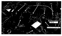
図9は、例示的な装置のプログラム可能なマルチバンドスペクトルフィルタリング能力が、いかにして、それらのスペクトル特性に基づいて互いに標的のいずれかのタイプを区別するために及びリアルタイム表示された画像内の特定のターゲットタイプをハイライト表示するために使用されることができるかを示す。 FIG. 9 shows how the programmable multi-band spectral filtering capability of an exemplary device distinguishes between any type of target from each other based on their spectral characteristics and in a real-time displayed image Indicates whether a particular target type can be used to highlight.
三つの全てのイメージにおいて、テストシーンは、二つの電球である、左側にある標準広域白熱灯と、右側にあるマルチライン離散スペクトルコンパクト蛍光ランプ(CFL)と、を含む。例示の装置で得られたCFLのスペクトルは、図8に示される。両方のランプは、全ての三つの画像の最大輝度で点灯しており、三つの画像で見られる明るさの違いは、電球自体の変化ではなく、プログラム可能なスペクトルフィルタの作用に起因する。 In all three images, the test scene includes two light bulbs, a standard wide incandescent lamp on the left and a multi-line discrete spectrum compact fluorescent lamp (CFL) on the right. The spectrum of CFL obtained with the exemplary apparatus is shown in FIG. Both lamps are lit at the maximum brightness of all three images, and the difference in brightness seen in the three images is due to the action of a programmable spectral filter, not a change in the bulb itself.
第1の画像(a)では、スペクトル選択マイクロミラーアレイは、CFLスペクトルの最も明るいスペクトル線に対応する三つの狭波長域を通過させるようにプログラムされていた。その光のほとんどは、これらのスペクトル帯域で放射されているため、CFLはこの画像で明るく見えるが、その連続スペクトルが同様にそれらのスペクトル帯でかなりのエネルギーが含まれているため、白熱灯もまた、比較的明るく見える。第2の画像(b)では、第二の画像(b)において、マイクロミラーアレイは、 CFLの主発光線の間に暗い領域内に位置する三つの狭波長スペクトル帯域を通過させるようにプログラムされていた。ほぼすべての離散スペクトル光がプログラム可能なフィルタによってブロックされているため、CFLは、この画像において暗く見える。しかしながら、その連続的なスペクトルの発光がスペクトル帯域のこの第2セットの同等のエネルギーを含んでいるため、白熱電球は、最初の画像と同じ明るさに見える。CFLの光は、両方のランプが点灯しているにもかかわらず白熱電球の反射がCFLの表面上に見ることができる、プログラム可能なフィルタによって、非常に効果的に抑制されたことは注目に値する。第三の画像(c)は、最初の二つの画像間の違いを示す。白熱ランプが例示的な装置の総合の応答性について正規化され、両方の画像において同じ集積エネルギーを含むように、最初の二つの画像内のスペクトル帯域幅が選択された。第3の差の画像では、白熱電球の明るさはバルブがオンであるにもかかわらず、ほぼゼロであるように見える。この場合には、白熱電球は、その表面からCFLの反射を見ることができることが非常に効果的に抑制される。この第三の画像は、背景が白熱灯スペクトルであり、ターゲットがCFLスペクトルである背景抑制整合フィルタ画像として考えることができる。同様のプロセスは、スペクトル的に複雑な背景に対して見た、化学気相のプルームからなるシーン内の特定の化学気を強調するために、一例として、赤外領域で使用されることができる。 In the first image (a), the spectrally selective micromirror array was programmed to pass three narrow wavelength bands corresponding to the brightest spectral lines of the CFL spectrum. Since most of the light is emitted in these spectral bands, the CFL appears bright in this image, but the incandescent lamp also has a continuous spectrum that contains significant energy in those spectral bands as well. Also, it looks relatively bright. In the second image (b), in the second image (b), the micromirror array is programmed to pass three narrow wavelength spectral bands located in the dark area between the main emission lines of the CFL. It was. The CFL appears dark in this image because almost all the discrete spectrum light is blocked by the programmable filter. However, the incandescent bulb appears to be as bright as the first image because its continuous spectral emission contains this second set of equivalent energy in the spectral band. Note that the CFL light was very effectively suppressed by a programmable filter that allowed the incandescent bulb reflections to be seen on the surface of the CFL even though both lamps were lit. Deserve. The third image (c) shows the difference between the first two images. The spectral bandwidth in the first two images was selected so that the incandescent lamp was normalized for the overall responsiveness of the exemplary device and contained the same integrated energy in both images. In the third difference image, the brightness of the incandescent bulb appears to be nearly zero despite the bulb being on. In this case, the incandescent bulb is very effectively suppressed from being able to see the reflection of CFL from its surface. This third image can be thought of as a background suppression matched filter image where the background is an incandescent lamp spectrum and the target is a CFL spectrum. A similar process can be used in the infrared region, as an example, to highlight a particular chemist in a scene consisting of a chemical vapor plume, viewed against a spectrally complex background. .
以上詳述したように、一般に、以下の特許請求の範囲に記載の原理は、マイクロレンズアレイ、マイクロルーバーアレイ及び/又は毛管アレイなどの微細加工された二次元のマイクロアレイの光学素子を組み込むことによって及び/又は分散素子へのイメージ位置の独立した一定の入射角度を形成するためのテレセントリック光学系を用いることによって、達成されることができる。本明細書で述べたように、所望の画像の生成は、マイクロミラーアレイ/複数のマイクロミラーアレイ、又は、他のアドレス可能な空間光変調装置/複数の空間光変調装置、によって選択された波長が、画像全体にわたって同じになるのを許容する。このようなフルフレーム機能に関し、選択されたスペクトルバンドはプログラムすることができ、それによりバックグラウンド抑制マッチドフィルタは、ミリ秒の時間スケールで、画像全体にわたってプログラムされると共に再プログラムされることができ、それによって、バックグラウンド抑制整合フィルタがリアルタイムのビデオレートで実施されるのを許容する。 As detailed above, in general, the principles set forth in the following claims are implemented by incorporating microfabricated two-dimensional microarray optical elements such as microlens arrays, microlouver arrays, and / or capillary arrays. And / or by using telecentric optics to create an independent and constant angle of incidence of the image position on the dispersive element. As described herein, the generation of the desired image is a wavelength selected by the micromirror array / multiple micromirror array or other addressable spatial light modulator / multiple spatial light modulators. Is the same throughout the image. For such full frame functions, the selected spectral band can be programmed so that the background suppression matched filter can be programmed and reprogrammed over the entire image on a millisecond time scale. Thereby allowing the background suppression matched filter to be implemented at real-time video rates.
好適な装置10、100のアプリケーションは、(伝統的なハイパースペクトル画像装置上の2乃至3桁減少された所定の領域を走査するために必要な時間で)軍事/諜報目標のための迅速な広帯域検索や、リアルタイム医療画像処理、迅速な過渡のスペクトル監視、車両や個人のスペクトルに基づいた追跡、及び、(適切な超高速検出器と組み合わせた場合における)ナノ秒時間スケールでの超高速分光画像処理の範囲にわたる。他のアプリケーションでは、好適な装置10、100は、任意の予め決められた化学物質、固体、液体、気体、物質、またはそれらの混合物のための、任意の予め決められた生物学的組織または医学的異常のための、任意の予め決められた鉱物の種類のための、及び、任意の法医学の署名のための、ペクトル整合フィルタとして使用されることができる。一例として、好適な装置10、100は、メタン、二酸化炭素、一酸化炭素、オゾン、またはエネルギー生産、産業、製造及び/又は輸送の他の任意の化学製品または副産物などの既知の分光特性を有する化学物質の特定のタイプのリモートセンサーとして配備されることができる。
The
本発明の前述の説明を通して、用語「光」は、紫外、可視、および赤外の波長を含む任意の波長の電磁放射線を意味することが理解されるべきであり、その発明は、特定の波長の範囲に限定されるものではないことが理解されるべきである。 Throughout the foregoing description of the invention, the term “light” should be understood to mean electromagnetic radiation of any wavelength, including ultraviolet, visible, and infrared wavelengths, and the invention is not limited to a particular wavelength. It should be understood that the present invention is not limited to the above range.
本発明の前述の説明は、例示および説明の目的で提示されており、開示された正確な形態に本発明を網羅的にする又は限定するものではなく、明らかに多くの修正及び変形が上記の教示に照らして可能である。実施形態は、本発明の原理及びその実際の応用を説明するために選択され説明され、それによって、他の当業者は、意図する特定の用途に適するように、様々な実施形態及び様々な変形例を最良に利用することができる。なお、本発明の範囲は添付の特許請求の範囲によって定義されることが意図される。 The foregoing description of the present invention has been presented for purposes of illustration and description, and is not intended to be exhaustive or to limit the invention to the precise form disclosed, and obviously many modifications and variations have been described above. This is possible in light of the teaching. The embodiments have been selected and described in order to explain the principles of the invention and its practical application, so that others skilled in the art will appreciate the various embodiments and various modifications to suit the particular application intended. The example can be used best. It is intended that the scope of the invention be defined by the appended claims.
Claims (28)
入射光を受光すると共に、イメージ面からなる第1の予め決められた位置で実質的に空間的に不変の入射角度を画定する空間的に不変の光伝播を備えるイメージを生成する最初の光学サブシステムと、
空間的に不変の入射角度でイメージを受け入れるため及び波長分散された光を生成するために、第1の予め決められた位置に配置された分散素子と、
波長分散された光を受け入れる第2の光学サブシステムであって、予め決められた波長の光が分光面の少なくとも一つの次元においてその分光面内で実質的に同一の位置に向くように第2の予め決められた位置で空間的に分散されたスペクトルを生成する、第2の光学サブシステムと、
第2の予め決められた位置に配置されると共に分散素子に光学的に結合された選択素子であって、スペクトル的に修正された光を生成するためにスペクトル平面における一つ以上の位置で光の振幅をプログラム可能に変調するように構成された、選択素子と、
選択素子からスペクトル的に修正された光を受け入れる検出器と、を備え、
スペクトル的に修正された光は、入射光のイメージ表現からなり、スペクトルコンテンツは、一つ以上のスペクトル帯域における選択素子によって修正され、そのようなスペクトルの修正は、イメージ表現の実質的にすべての位置に対して実質的に同一である、イメージシステム。 An image system,
A first optical sub that receives incident light and generates an image with spatially invariant light propagation that defines a substantially spatially invariant incident angle at a first predetermined position of the image plane. System,
A dispersive element disposed at a first predetermined position for receiving an image at a spatially invariant angle of incidence and for generating chromatically dispersed light;
A second optical subsystem for accepting wavelength-dispersed light, wherein the second wavelength is such that light of a predetermined wavelength is directed to substantially the same position in the spectral plane in at least one dimension of the spectral plane. A second optical subsystem that produces a spatially dispersed spectrum at a predetermined position of
A selection element disposed at a second predetermined position and optically coupled to the dispersive element, wherein the light at one or more positions in the spectral plane to produce spectrally modified light. A selection element configured to programmably modulate the amplitude of
Receiving a spectrally modified light from the selection element, and
Spectrally modified light consists of an image representation of incident light, the spectral content is modified by a selection element in one or more spectral bands, and such spectral modification is substantially all of the image representation. An image system that is substantially identical to position.
検出器に結合されると共に、入射光のマルチスペクトルイメージ表現の少なくとも一部を表示するように構成されたディスプレイを更に備える、イメージシステム。 The image system according to claim 1,
An image system further comprising a display coupled to the detector and configured to display at least a portion of the multispectral image representation of incident light.
最初の光学サブシステムは、テレセントリック結像レンズからなる、イメージシステム。 The image system according to claim 1,
The first optical subsystem is an image system consisting of a telecentric imaging lens.
最初の光学サブシステムは、撮像素子及びマイクロレンズアレイからなる、イメージシステム。 The image system according to claim 1,
The first optical subsystem is an image system consisting of an image sensor and a microlens array.
マイクロレンズアレイに光学的に結合された開口アレイを更に備える、イメージシステム。 The image system according to claim 4.
An image system further comprising an aperture array optically coupled to the microlens array.
最初の光学サブシステムは、撮像素子及び毛管アレイからなる、イメージシステム。 The image system according to claim 1,
The first optical subsystem is an image system consisting of an image sensor and a capillary array.
最初の光学サブシステムは、撮像素子及びマイクロルーバーアレイからなる、イメージシステム。 The image system according to claim 1,
The first optical subsystem is an image system consisting of an image sensor and a microlouver array.
分散素子は、屈折格子、透過格子、回折分散器、干渉分散器、又は、屈折分散器のいずれかからなる、イメージシステム。 The image system according to claim 1,
The dispersive element is an image system including any one of a refractive grating, a transmission grating, a diffractive distributor, an interference distributor, and a refractive distributor.
分散素子は、屈折格子、透過格子、回折分散器、干渉分散器、又は、屈折分散器のいず
れかからなる、イメージシステム。 The image system according to claim 3.
The dispersive element is an image system including any one of a refractive grating, a transmission grating, a diffractive distributor, an interference distributor, and a refractive distributor.
分散素子は、屈折格子、透過格子、回折分散器、干渉分散器、又は、屈折分散器のいずれかからなる、イメージシステム。 The image system according to claim 4.
The dispersive element is an image system including any one of a refractive grating, a transmission grating, a diffractive distributor, an interference distributor, and a refractive distributor.
分散素子は、屈折格子、透過格子、回折分散器、干渉分散器、又は、屈折分散器のいずれかからなる、イメージシステム。 The image system according to claim 6.
The dispersive element is an image system including any one of a refractive grating, a transmission grating, a diffractive distributor, an interference distributor, and a refractive distributor.
分散素子は、屈折格子、透過格子、回折分散器、干渉分散器、又は、屈折分散器のいずれかからなる、イメージシステム。 The image system according to claim 7,
The dispersive element is an image system including any one of a refractive grating, a transmission grating, a diffractive distributor, an interference distributor, and a refractive distributor.
選択素子は、マイクロシャッタアレイ、LCDアレイ、マイクロミラーアレイ、マスク又はスリットアレイのいずれかからなる、イメージシステム。 The image system according to claim 1,
The selection device is an image system including a micro shutter array, an LCD array, a micro mirror array, a mask, or a slit array.
選択素子は、マイクロシャッタアレイ、LCDアレイ、マイクロミラーアレイ、マスク又はスリットアレイのいずれかからなる、イメージシステム。 The image system according to claim 9.
The selection device is an image system including a micro shutter array, an LCD array, a micro mirror array, a mask, or a slit array.
選択素子は、マイクロシャッタアレイ、LCDアレイ、マイクロミラーアレイ、マスク又はスリットアレイのいずれかからなる、イメージシステム。 The image system according to claim 10.
The selection device is an image system including a micro shutter array, an LCD array, a micro mirror array, a mask, or a slit array.
選択素子は、マイクロシャッタアレイ、LCDアレイ、マイクロミラーアレイ、マスク又はスリットアレイのいずれかからなる、イメージシステム。 12. The image system according to claim 11, wherein
The selection device is an image system including a micro shutter array, an LCD array, a micro mirror array, a mask, or a slit array.
選択素子は、マイクロシャッタアレイ、LCDアレイ、マイクロミラーアレイ、マスク又はスリットアレイのいずれかからなる、イメージシステム。 The image system according to claim 12,
The selection device is an image system including a micro shutter array, an LCD array, a micro mirror array, a mask, or a slit array.
選択素子は、マイクロシャッタアレイ、LCDアレイ、マイクロミラーアレイ、マスク又はスリットアレイのいずれかからなる、イメージシステム。 The image system according to claim 13.
The selection device is an image system including a micro shutter array, an LCD array, a micro mirror array, a mask, or a slit array.
最初の光学サブシステムと入射光源との間に配置された入射瞳を更に備える、イメージシステム。 The image system according to claim 1,
An image system further comprising an entrance pupil disposed between the first optical subsystem and the entrance light source.
入射瞳は、スリット状の入射瞳、物理的スリット状の入射瞳と結合されたマイクロミラーアレイ、又は、スリット状の入射瞳を擬態するようにプログラムされたマイクロミラーアレイのいずれかからなる、イメージシステム。 The image system of claim 19, wherein
The entrance pupil consists of either a slit-like entrance pupil, a micromirror array combined with a physical slit-like entrance pupil, or a micromirror array programmed to mimic a slit-like entrance pupil. system.
選択素子は、プログラム可能なマイクロミラーアレイからなり、
イメージシステムは、最初の光学サブシステムと入射光源との間に配置された第2のプ
ログラム可能なマイクロミラーアレイを更に備える、イメージシステム。 The image system according to claim 1,
The selection element consists of a programmable micromirror array,
The image system further comprises a second programmable micromirror array disposed between the first optical subsystem and the incident light source.
検出器に結合されると共に、入射光のマルチスペクトルイメージ表現にハイパースペクトル画像処理を行うように構成されたコントローラを更に備える、イメージシステム。 The image system according to claim 1,
An image system further comprising a controller coupled to the detector and configured to perform hyperspectral image processing on a multispectral image representation of incident light.
コントローラは、検出器と一体化されている、イメージシステム。 The image system of claim 22,
The controller is an image system that is integrated with the detector.
選択素子は、アダマール変換技術によってハイパースペクトル画像処理を行うようにプログラム可能である、イメージシステム。 The image system according to claim 1,
The selection element is programmable to perform hyperspectral image processing by Hadamard transform technology.
選択素子は、予め決められた化学物質、固体、液体、気体、物質、またはそれらの混合物のためのスペクトル整合フィルタとしてプログラム可能である、イメージシステム。 The image system according to claim 1,
An imaging system, wherein the selection element is programmable as a spectrally matched filter for a predetermined chemical, solid, liquid, gas, substance, or mixture thereof.
選択素子は、予め決められた生物学的組織または医学的異常のためのスペクトル整合フィルタとしてプログラム可能である、イメージシステム。 The image system according to claim 1,
The image system, wherein the selection element is programmable as a spectrally matched filter for a predetermined biological tissue or medical abnormality.
選択素子は、予め決められた鉱物の種類のためのスペクトル整合フィルタとしてプログラム可能である、イメージシステム。 The image system according to claim 1,
An image system, wherein the selection element is programmable as a spectrally matched filter for a predetermined mineral type.
選択素子は、法医学署名のためのスペクトル整合フィルタとしてプログラム可能である、イメージシステム。 The image system according to claim 1,
An image system, wherein the selection element is programmable as a spectrally matched filter for forensic signatures.
Applications Claiming Priority (2)
| Application Number | Priority Date | Filing Date | Title |
|---|---|---|---|
| US201161541789P | 2011-09-30 | 2011-09-30 | |
| US61/541,789 | 2011-09-30 |
Related Parent Applications (1)
| Application Number | Title | Priority Date | Filing Date |
|---|---|---|---|
| JP2014533513A Division JP2015501417A (en) | 2011-09-30 | 2012-09-28 | Full frame programmable hyperspectral imager |
Publications (2)
| Publication Number | Publication Date |
|---|---|
| JP2017138327A true JP2017138327A (en) | 2017-08-10 |
| JP6386614B2 JP6386614B2 (en) | 2018-09-05 |
Family
ID=47996273
Family Applications (2)
| Application Number | Title | Priority Date | Filing Date |
|---|---|---|---|
| JP2014533513A Pending JP2015501417A (en) | 2011-09-30 | 2012-09-28 | Full frame programmable hyperspectral imager |
| JP2017075912A Active JP6386614B2 (en) | 2011-09-30 | 2017-04-06 | Full frame programmable hyperspectral imager |
Family Applications Before (1)
| Application Number | Title | Priority Date | Filing Date |
|---|---|---|---|
| JP2014533513A Pending JP2015501417A (en) | 2011-09-30 | 2012-09-28 | Full frame programmable hyperspectral imager |
Country Status (4)
| Country | Link |
|---|---|
| US (1) | US9716846B2 (en) |
| JP (2) | JP2015501417A (en) |
| DE (1) | DE112012004100T5 (en) |
| WO (1) | WO2013048548A1 (en) |
Families Citing this family (21)
| Publication number | Priority date | Publication date | Assignee | Title |
|---|---|---|---|---|
| US9880054B2 (en) * | 2013-07-26 | 2018-01-30 | Inview Technology Corporation | Simplified compressive sensing spectral imager |
| CN103616074B (en) * | 2013-11-21 | 2015-06-10 | 中国科学院长春光学精密机械与物理研究所 | Wavelength calibration method for digital micromirror grating spectrometer |
| CN103679673B (en) * | 2013-11-22 | 2016-06-08 | 中国资源卫星应用中心 | A kind of wide visual field linear CCD image geometric distortion analogy method |
| FR3021127B1 (en) * | 2014-05-19 | 2017-10-13 | Commissariat Energie Atomique | SYSTEM AND METHOD FOR ACQUIRING HYPERSPECTRAL IMAGES |
| CN109163805B (en) | 2014-11-19 | 2022-03-22 | 松下知识产权经营株式会社 | Light splitting system |
| US9395293B1 (en) | 2015-01-12 | 2016-07-19 | Verily Life Sciences Llc | High-throughput hyperspectral imaging with superior resolution and optical sectioning |
| CN105758428B (en) * | 2016-03-31 | 2018-07-03 | 中国科学院西安光学精密机械研究所 | Utilize the method for caliberating device calibration dynamic target dynamic deformation angle error |
| JP6682380B2 (en) * | 2016-06-22 | 2020-04-15 | リコーインダストリアルソリューションズ株式会社 | Gas image sensor device, gas image capturing / measuring device, and gas image capturing / measuring system |
| DE102016008884B4 (en) * | 2016-07-20 | 2022-05-19 | Institut für Lasertechnologien in der Medizin und Meßtechnik an der Universität Ulm | Spectroscopy apparatus and method |
| WO2018113939A1 (en) * | 2016-12-21 | 2018-06-28 | CSEM Centre Suisse d'Electronique et de Microtechnique SA - Recherche et Développement | Optical system |
| WO2018113938A1 (en) * | 2016-12-21 | 2018-06-28 | CSEM Centre Suisse d'Electronique et de Microtechnique SA - Recherche et Développement | Optical system |
| US20180188110A1 (en) * | 2016-12-29 | 2018-07-05 | Verifood, Ltd. | Fabry-perot spectrometer apparatus and methods |
| WO2018191694A1 (en) | 2017-04-14 | 2018-10-18 | Arizona Board Of Regents On Behalf Of The University Of Arizona | Methods and apparatus for angular and spatial modulation of light |
| WO2018191696A1 (en) * | 2017-04-14 | 2018-10-18 | Arizona Board Of Regents On Behalf Of The University Of Arizona | Methods and apparatus employing angular and spatial modulation of light |
| WO2018191630A1 (en) | 2017-04-14 | 2018-10-18 | Arizona Board Of Regents On Behalf Of The University Of Arizona | Systems and methods for beam steering using a micromirror device |
| WO2019126637A1 (en) | 2017-12-22 | 2019-06-27 | Arizona Board Of Regents On Behalf Of The University Of Arizona | Methods and apparatus for angular and spatial modulation of light |
| JP7260966B2 (en) * | 2018-02-19 | 2023-04-19 | 京セラ株式会社 | Electromagnetic wave detector |
| CN108414096B (en) * | 2018-02-22 | 2020-03-06 | 清华大学 | Wide-field tomography method and device based on adaptive optics |
| SE542835C2 (en) * | 2019-06-28 | 2020-07-14 | Guenot Diego | Optical spectrometer and method for spectrally resolved two-dimensional imaging of an object |
| CN112022093B (en) * | 2020-08-17 | 2023-11-07 | 苏州大学 | Skin imaging system |
| CN113654653B (en) * | 2021-08-13 | 2023-06-09 | 中国工程物理研究院激光聚变研究中心 | Single measurement method for ultrafast laser space-time coupling characteristic |
Citations (8)
| Publication number | Priority date | Publication date | Assignee | Title |
|---|---|---|---|---|
| JP2000267062A (en) * | 1999-03-15 | 2000-09-29 | Hiihaisuto Seiko Kk | Wide band transmittance variable filter |
| JP2001519913A (en) * | 1998-01-30 | 2001-10-23 | サントル、ナショナール、ド、ラ、ルシェルシュ、シアンティフィク、(セーエヌエルエス) | Improvement of multi-capillary electrophoresis system |
| JP2006259153A (en) * | 2005-03-16 | 2006-09-28 | Fuji Photo Film Co Ltd | Method and device for evaluating alignment accuracy |
| JP2010067441A (en) * | 2008-09-10 | 2010-03-25 | Dainippon Printing Co Ltd | Back light unit and liquid crystal display device |
| JP2010096559A (en) * | 2008-10-15 | 2010-04-30 | Konica Minolta Sensing Inc | Two-dimensional optical spectrometer |
| WO2010053979A2 (en) * | 2008-11-04 | 2010-05-14 | William Marsh Rice University | Image mapping spectrometers |
| US20100309467A1 (en) * | 2009-06-05 | 2010-12-09 | Spectral Sciences, Inc. | Single-Shot Spectral Imager |
| JP2011118070A (en) * | 2009-12-02 | 2011-06-16 | Olympus Corp | Confocal scanning microscope |
Family Cites Families (14)
| Publication number | Priority date | Publication date | Assignee | Title |
|---|---|---|---|---|
| US4494872A (en) * | 1980-10-07 | 1985-01-22 | Baylor University | Multiple entrance aperture dispersive optical spectrometer |
| US6504943B1 (en) * | 1998-07-20 | 2003-01-07 | Sandia Corporation | Information-efficient spectral imaging sensor |
| US20050270528A1 (en) * | 1999-04-09 | 2005-12-08 | Frank Geshwind | Hyper-spectral imaging methods and devices |
| US7180588B2 (en) * | 1999-04-09 | 2007-02-20 | Plain Sight Systems, Inc. | Devices and method for spectral measurements |
| US6886953B2 (en) * | 2002-03-22 | 2005-05-03 | Raytheon Company | High-resolution, all-reflective imaging spectrometer |
| US6996292B1 (en) * | 2002-04-18 | 2006-02-07 | Sandia Corporation | Staring 2-D hadamard transform spectral imager |
| US6813018B2 (en) * | 2002-11-07 | 2004-11-02 | The Boeing Company | Hyperspectral imager |
| US7119911B2 (en) | 2003-03-07 | 2006-10-10 | Lsa, Inc. | Moiré deflectometer including non-mechanical, transparent, spatial light modulators for demonstrating two-axis rulings |
| US7420679B2 (en) * | 2004-06-30 | 2008-09-02 | Chemimage Corporation | Method and apparatus for extended hyperspectral imaging |
| US7289209B2 (en) * | 2004-07-22 | 2007-10-30 | Eastman Kodak Company | Programmable spectral imaging system |
| US7274454B2 (en) * | 2005-12-23 | 2007-09-25 | Eastman Kodak Company | Imaging system with programmable spectral switch |
| GB0809252D0 (en) * | 2008-05-21 | 2008-06-25 | Ntnu Technology Transfer As | Underwater hyperspectral imaging |
| US9752932B2 (en) * | 2010-03-10 | 2017-09-05 | Drexel University | Tunable electro-optic filter stack |
| US8400574B2 (en) * | 2010-04-16 | 2013-03-19 | Chemimage Corporation | Short wave infrared multi-conjugate liquid crystal tunable filter |
-
2012
- 2012-09-28 US US14/348,001 patent/US9716846B2/en active Active
- 2012-09-28 DE DE112012004100.3T patent/DE112012004100T5/en active Pending
- 2012-09-28 JP JP2014533513A patent/JP2015501417A/en active Pending
- 2012-09-28 WO PCT/US2012/000417 patent/WO2013048548A1/en active Application Filing
-
2017
- 2017-04-06 JP JP2017075912A patent/JP6386614B2/en active Active
Patent Citations (8)
| Publication number | Priority date | Publication date | Assignee | Title |
|---|---|---|---|---|
| JP2001519913A (en) * | 1998-01-30 | 2001-10-23 | サントル、ナショナール、ド、ラ、ルシェルシュ、シアンティフィク、(セーエヌエルエス) | Improvement of multi-capillary electrophoresis system |
| JP2000267062A (en) * | 1999-03-15 | 2000-09-29 | Hiihaisuto Seiko Kk | Wide band transmittance variable filter |
| JP2006259153A (en) * | 2005-03-16 | 2006-09-28 | Fuji Photo Film Co Ltd | Method and device for evaluating alignment accuracy |
| JP2010067441A (en) * | 2008-09-10 | 2010-03-25 | Dainippon Printing Co Ltd | Back light unit and liquid crystal display device |
| JP2010096559A (en) * | 2008-10-15 | 2010-04-30 | Konica Minolta Sensing Inc | Two-dimensional optical spectrometer |
| WO2010053979A2 (en) * | 2008-11-04 | 2010-05-14 | William Marsh Rice University | Image mapping spectrometers |
| US20100309467A1 (en) * | 2009-06-05 | 2010-12-09 | Spectral Sciences, Inc. | Single-Shot Spectral Imager |
| JP2011118070A (en) * | 2009-12-02 | 2011-06-16 | Olympus Corp | Confocal scanning microscope |
Non-Patent Citations (1)
| Title |
|---|
| LOVE, STEVEN P.: ""Prgrammable matched filter and Hadamard transform hyperspectral imagers based on micro-mirror array", PROC. OF SPIE, vol. 7210, JPN6016016297, 2009, pages 721007 - 1, ISSN: 0003681256 * |
Also Published As
| Publication number | Publication date |
|---|---|
| DE112012004100T5 (en) | 2014-07-10 |
| US20140240514A1 (en) | 2014-08-28 |
| JP6386614B2 (en) | 2018-09-05 |
| US9716846B2 (en) | 2017-07-25 |
| JP2015501417A (en) | 2015-01-15 |
| WO2013048548A1 (en) | 2013-04-04 |
Similar Documents
| Publication | Publication Date | Title |
|---|---|---|
| JP6386614B2 (en) | Full frame programmable hyperspectral imager | |
| AU731476B2 (en) | Multi-spectral two-dimensional imaging spectrometer | |
| US5982497A (en) | Multi-spectral two-dimensional imaging spectrometer | |
| US7324196B2 (en) | Spectral encoder | |
| US7692784B2 (en) | Apparatus and methods relating to enhanced spectral measurement systems | |
| US7636158B1 (en) | Optimal coupling of high performance line imaging spectrometer to imaging system | |
| US8339600B2 (en) | Dual waveband compact catadioptric imaging spectrometer | |
| JP5953230B2 (en) | Spectral detector or laser scanning microscope using variable filtering with spatial color separation | |
| US9052290B2 (en) | SWIR targeted agile raman system for detection of unknown materials using dual polarization | |
| US9528878B2 (en) | Imaging apparatus and microscope system having the same | |
| US11112309B2 (en) | Digital micromirror device and kinematically tunable wavelength filter-based imaging systems | |
| JP2011075562A (en) | Adjustable multimode lightfield imaging system | |
| US20090201499A1 (en) | Spectroscopic Imaging Microscopy | |
| Love et al. | Full-frame programmable spectral filters based on micromirror arrays | |
| KR20150116999A (en) | Micro Raman and photo-luminescence spectral analysis apparatus for multi-channel excitation laser source switching | |
| US20150022810A1 (en) | Spectrophotometer and image partial extraction device | |
| US7359050B1 (en) | Compact triple pass hyperspectral imager | |
| US9835491B1 (en) | Spectral, polar and spectral-polar imagers for use in space situational awareness | |
| CN109556716A (en) | A kind of imaging spectrometer and its ultra-optical spectrum imaging method based on diffraction effect | |
| Love et al. | Full-frame programmable spectral filters based on micro-mirror arrays | |
| Graff et al. | Toward real-time spectral imaging for chemical detection with a digital micromirror device-based programmable spectral filter | |
| JP6682380B2 (en) | Gas image sensor device, gas image capturing / measuring device, and gas image capturing / measuring system | |
| Pust | Optical filters–Technology and applications | |
| Elahi et al. | A grating-optic-less visible spectrometer using Fresnel zone plate patterns on a digital light processor | |
| Graff et al. | Real-time video imaging of gas plumes using a DMD-enabled full-frame programmable spectral filter |
Legal Events
| Date | Code | Title | Description |
|---|---|---|---|
| A977 | Report on retrieval |
Free format text: JAPANESE INTERMEDIATE CODE: A971007 Effective date: 20171109 |
|
| A131 | Notification of reasons for refusal |
Free format text: JAPANESE INTERMEDIATE CODE: A131 Effective date: 20171114 |
|
| A601 | Written request for extension of time |
Free format text: JAPANESE INTERMEDIATE CODE: A601 Effective date: 20180206 |
|
| A521 | Request for written amendment filed |
Free format text: JAPANESE INTERMEDIATE CODE: A523 Effective date: 20180308 |
|
| TRDD | Decision of grant or rejection written | ||
| A01 | Written decision to grant a patent or to grant a registration (utility model) |
Free format text: JAPANESE INTERMEDIATE CODE: A01 Effective date: 20180711 |
|
| A61 | First payment of annual fees (during grant procedure) |
Free format text: JAPANESE INTERMEDIATE CODE: A61 Effective date: 20180809 |
|
| R150 | Certificate of patent or registration of utility model |
Ref document number: 6386614 Country of ref document: JP Free format text: JAPANESE INTERMEDIATE CODE: R150 |
|
| R250 | Receipt of annual fees |
Free format text: JAPANESE INTERMEDIATE CODE: R250 |
|
| R250 | Receipt of annual fees |
Free format text: JAPANESE INTERMEDIATE CODE: R250 |
|
| R250 | Receipt of annual fees |
Free format text: JAPANESE INTERMEDIATE CODE: R250 |