JP2017138034A - Refrigerating device - Google Patents
Refrigerating device Download PDFInfo
- Publication number
- JP2017138034A JP2017138034A JP2016018048A JP2016018048A JP2017138034A JP 2017138034 A JP2017138034 A JP 2017138034A JP 2016018048 A JP2016018048 A JP 2016018048A JP 2016018048 A JP2016018048 A JP 2016018048A JP 2017138034 A JP2017138034 A JP 2017138034A
- Authority
- JP
- Japan
- Prior art keywords
- oil
- low
- refrigerant
- temperature
- stage
- Prior art date
- Legal status (The legal status is an assumption and is not a legal conclusion. Google has not performed a legal analysis and makes no representation as to the accuracy of the status listed.)
- Granted
Links
Images


Landscapes
- Devices That Are Associated With Refrigeration Equipment (AREA)
Abstract
Description
本発明は、オイルセパレータで分離されたオイルを、少なくとも一つの圧縮機の内部に戻すオイル戻し回路を備えた冷凍装置に関する。 The present invention relates to a refrigeration apparatus including an oil return circuit that returns oil separated by an oil separator to the inside of at least one compressor.
従来、この種の冷凍装置は、例えば特許文献1に記載されている。この冷凍装置は、ケース内が中間圧となる多段式の圧縮機と、この圧縮機の高圧吐出管に設けられたオイルセパレータと、オイルセパレータで捕捉したオイルを冷却するオイルクーラと、オイルクーラで冷却されたオイルをケース内に戻すオイル戻し管と、このオイル戻し管に設けられた電動弁と、電動弁の弁開度を圧縮機の運転周波数に応じて調整する弁開度調整手段と、を備えている。
Conventionally, this kind of refrigeration apparatus is described in
従来の冷凍装置では、運転条件によっては、負荷安定時に、オイルセパレータからオイルクーラを経て圧縮機に戻されるオイル循環量が少なくなる。その結果、圧縮機やオイルの温度が高くなり過ぎて、冷凍装置の運転信頼性が低下するという問題点があった。 In the conventional refrigeration system, the amount of oil circulation returned from the oil separator to the compressor via the oil cooler decreases when the load is stable depending on the operating conditions. As a result, the temperature of the compressor and oil becomes too high, and there is a problem that the operation reliability of the refrigeration apparatus is lowered.
それゆえに、本発明の目的は、運転信頼性を向上可能な冷凍装置を提供することである。 Therefore, an object of the present invention is to provide a refrigeration apparatus capable of improving operation reliability.
本発明の一局面は、冷凍装置であって、前記冷凍装置の入口を通じて低段吸込口から冷媒が吸入され、複数段圧縮を行って高段吐出口から冷媒を吐出する圧縮機と、前記高段吐出口からの吐出冷媒からオイルを分離するオイルセパレータと、前記オイルセパレータで分離されたオイルを冷却するオイルクーラと、前記オイルクーラで冷却されたオイルを前記圧縮機に戻すオイル戻し回路と、所定の温度情報に基づき、前記オイル戻し回路でのオイル循環量が少ない状態にあるとみなすと、前記オイル戻し回路内を流れるオイル循環量を増大させる制御部と、を備えている。 One aspect of the present invention is a refrigeration apparatus, in which a refrigerant is sucked from a low-stage suction port through an inlet of the refrigeration apparatus, performs a multi-stage compression, and discharges the refrigerant from a high-stage discharge port; An oil separator that separates oil from refrigerant discharged from the stage discharge port, an oil cooler that cools the oil separated by the oil separator, and an oil return circuit that returns the oil cooled by the oil cooler to the compressor; A control unit that increases the amount of oil circulation flowing in the oil return circuit when it is considered that the amount of oil circulation in the oil return circuit is small based on predetermined temperature information.
また、他の局面は、冷凍装置であって、前記冷凍装置の入口を通じて低段吸込口から吸入された冷媒を圧縮して低段吐出口から吐出する圧縮機と、前記低段吐出口からの吐出冷媒を冷却するインタークーラと、を備え、前記圧縮機は、前記インタークーラで冷却された冷媒が高段吸込口から吸入されると、吸入冷媒を圧縮して高段吐出口から吐出し、前記冷凍装置はさらに、前記高段吐出口の吐出冷媒からオイルを分離するオイルセパレータと、前記オイルセパレータで分離されたオイルを冷却するオイルクーラと、前記オイルクーラで冷却されたオイルを前記圧縮機に戻すオイル戻し回路と、前記低段吐出口の吐出冷媒の温度が所定温度以上であれば、前記オイル戻し回路内を流れるオイル循環を増大させる制御部と、を備えている。 In another aspect, the refrigeration apparatus includes a compressor that compresses the refrigerant sucked from the low-stage suction port through the inlet of the refrigeration apparatus and discharges the refrigerant from the low-stage discharge port. An intercooler that cools the discharged refrigerant, and the compressor compresses the sucked refrigerant and discharges it from the high stage discharge port when the refrigerant cooled by the intercooler is sucked from the high stage suction port. The refrigeration apparatus further includes an oil separator that separates oil from refrigerant discharged from the high-stage discharge port, an oil cooler that cools oil separated by the oil separator, and oil that is cooled by the oil cooler as the compressor And an oil return circuit for returning the oil to the oil return circuit when the temperature of the refrigerant discharged from the low-stage discharge port is equal to or higher than a predetermined temperature.
上記各局面によれば、運転信頼性を向上可能な冷凍装置を提供することが出来る。 According to each said aspect, the refrigerating device which can improve driving | operation reliability can be provided.
≪1.実施形態≫
以下、上記図面を参照して、一実施形態に係る冷凍装置Aを詳説する。
<< 1. Embodiment >>
Hereinafter, with reference to the said drawings, the refrigeration apparatus A which concerns on one Embodiment is explained in full detail.
≪1−1.冷凍装置Aの大略的な構成≫
図1において、冷凍装置Aは、例えばコンビニエンスストア等の店舗外(例えば屋上)に設置される。また、冷凍装置Aは、ガス冷媒配管P1および液冷媒配管P8を用いて店舗内に設置されたショーケース(図示せず)と接続されて冷凍サイクルを構成し、ショーケースに陳列された商品群を冷凍・冷蔵する。この冷凍サイクルでは、冷媒としてCO2が使用される。
<< 1-1. Schematic configuration of refrigeration apparatus A >>
In FIG. 1, the refrigeration apparatus A is installed outside a store (for example, a rooftop) such as a convenience store. In addition, the refrigeration apparatus A is connected to a showcase (not shown) installed in the store using the gas refrigerant pipe P1 and the liquid refrigerant pipe P8 to constitute a refrigeration cycle, and a product group displayed in the showcase Freeze and refrigerate. In this refrigeration cycle, CO 2 is used as a refrigerant.
冷凍装置Aは、大略的に、例えば二台の圧縮機1a,1bと、インタークーラ2と、ファン3と、オイルセパレータ4と、ガスクーラ(放熱器)5と、タンク6と、スプリット熱交換器7と、オイル戻し回路8と、オイルクーラ9と、電動弁10a,10bと、を備えている。
The refrigeration apparatus A generally includes, for example, two
圧縮機1a,1bは、冷凍サイクルにおいて並列に配置される。
圧縮機1a,1bのケース11a,11bの内部には、低段圧縮要素12a,12bと、高段圧縮要素13a,13bと、が設けられる。各圧縮要素12a,13aは、ケース11aの内部に配置されたモータ(図示せず)の回転と同期回転する。同様に、圧縮要素12b,13bも、ケース11b内のモータ(図示せず)と同期して回転する。かかる回転により、低段圧縮要素12a,12bは、冷凍装置Aの入口Pinからガス冷媒配管P1を通じて圧縮機1a,1bの低段吸込口14a,14bから吸入された低圧の冷媒を中間圧まで昇圧する。かかる中間圧の冷媒を、低段圧縮要素12a,12bは圧縮機1a,1bの低段吐出口15a,15bから吐出する。
The
Low-
また、高段圧縮要素13a,13bの高段吸込口16a,16bには、低段圧縮要素12a,12bで圧縮された中間圧の冷媒が吸入される。高段圧縮要素13a,13bは、吸入冷媒を更に高圧まで昇圧して高段吐出口17a,17bから吐出する。
以上のように、本実施形態では、圧縮機1a,1bは冷媒を二段圧縮している。
Further, the intermediate pressure refrigerant compressed by the low-
As described above, in the present embodiment, the
また、圧縮機1a,1bは、後述の制御部20による制御下でモータの運転周波数を変更する。この制御により、低段圧縮要素12a,12b及び高段圧縮要素13a,13bの回転数が調整可能となっている。
The
低段吐出口15a,15bには、中間圧吐出管P3,P4が接続される。中間圧吐出管P3,P4は、低段吐出口15a,15bの下流側で合流した後、インタークーラ2に接続される。また、インタークーラ2の近くにはファン3が配置される。インタークーラ2は、低段圧縮要素12a,12bの吐出冷媒を、ファン3からのエアフローで冷却する。インタークーラ2は、冷却した冷媒を吐出ポートから吐出する。この出力ポートには中間圧吸入管P5が接続される。中間圧吸入管P5は、高段吸込口16a,16bの直ぐ上流側で二分岐した後に、高段吸込口16a,16bに接続される。高段圧縮要素13a,13bは、中間圧の冷媒を高段吸込口16a,16bから吸い込んで、更に高圧まで昇圧して高段吐出口17a,17bから吐出する。
Intermediate pressure discharge pipes P3 and P4 are connected to the low-
また、高段吐出口17a,17bには高圧吐出管P6,P7が接続される。高圧吐出管P6,P7は、高段吐出口17a,17bの下流側で合流した後、オイルセパレータ4に接続され、ガスクーラ5、タンク6及びスプリット熱交換器7を経て、液冷媒配管P8と接続される。
Further, high-pressure discharge pipes P6 and P7 are connected to the high
オイルセパレータ4は、高段吐出口17a,17bの吐出冷媒中に含まれるオイルを冷媒から分離して捕捉する。オイルセパレータ4にはさらに、捕捉したオイルを圧縮機1a,1bに戻すオイル戻し回路8が接続される。図1中、戻し回路8は太い点線で示される。オイル戻し回路8においてオイルセパレータ4の直ぐ下流には、オイルクーラ9が設けられる。オイルクーラ9は、捕捉したオイルを冷却する。本実施形態では、オイルクーラ9は、インタークーラ2の一部を用いて実現され、吸込ポートから吸い込まれたオイルをファン3からのエアフローを用いて冷却して吐出ポートから吐出する。オイル戻し回路8は、オイルクーラ9の下流側で二系統に分岐され、流量調整用の電動弁10a,10bを介して圧縮機1a,1bのケース11a,11bに接続される。
The oil separator 4 separates and captures the oil contained in the refrigerant discharged from the high-
また、オイルセパレータ4の吐出ポートは、ガスクーラ5の吸込ポートとも接続される。オイルが分離された冷媒は、オイルセパレータ4の吐出ポートからガスクーラ5の吸込ポートに向けて吐出される。ガスクーラ5は、吸込ポートから吸入冷媒を、自身に近接配置されたファン3からのエアフローで冷却し、冷却した冷媒を、自身の吐出ポートからタンク6に向けて吐出する。
The discharge port of the oil separator 4 is also connected to the suction port of the gas cooler 5. The refrigerant from which the oil has been separated is discharged from the discharge port of the oil separator 4 toward the suction port of the gas cooler 5. The gas cooler 5 cools the refrigerant sucked from the suction port by the air flow from the fan 3 disposed close to the gas cooler 5 and discharges the cooled refrigerant toward the
タンク6は所定容積の空間を有する。ガスクーラ5の吐出冷媒は、減圧電動弁61により減圧・冷却されてタンク6の上部から内部空間に吸入される。タンク6の下部からは、スプリット熱交換器7の第二流路72に向けて液冷媒が吐出される。また、タンク6の上部からは、ガス戻し電動弁62を介して、スプリット熱交換器7の第一流路71向けて、ガス冷媒が吐出される。
The
スプリット熱交換器7において、タンク6下部からの吐出冷媒は第二流路72を通過すると共に、タンク6上部からの吐出冷媒と第二流路72からの吐出冷媒の一部とが第一流路71を通過する。これにより、第二流路72を通過する冷媒が過冷却される。過冷却された冷媒の大部分は、液冷媒配管P8を通じて、冷凍装置Aの出口Poutから、ショーケース(図示せず)に向けて吐出されるが、上述の通り、一部は、液戻し電動弁63を介して、第一流路71に戻される。また、第一流路71を通過した冷媒は、中間圧吸入管P5を介して、高段圧縮要素13a,13bの高段吸込口16a,16bから吸入される。
In the split heat exchanger 7, the refrigerant discharged from the lower part of the
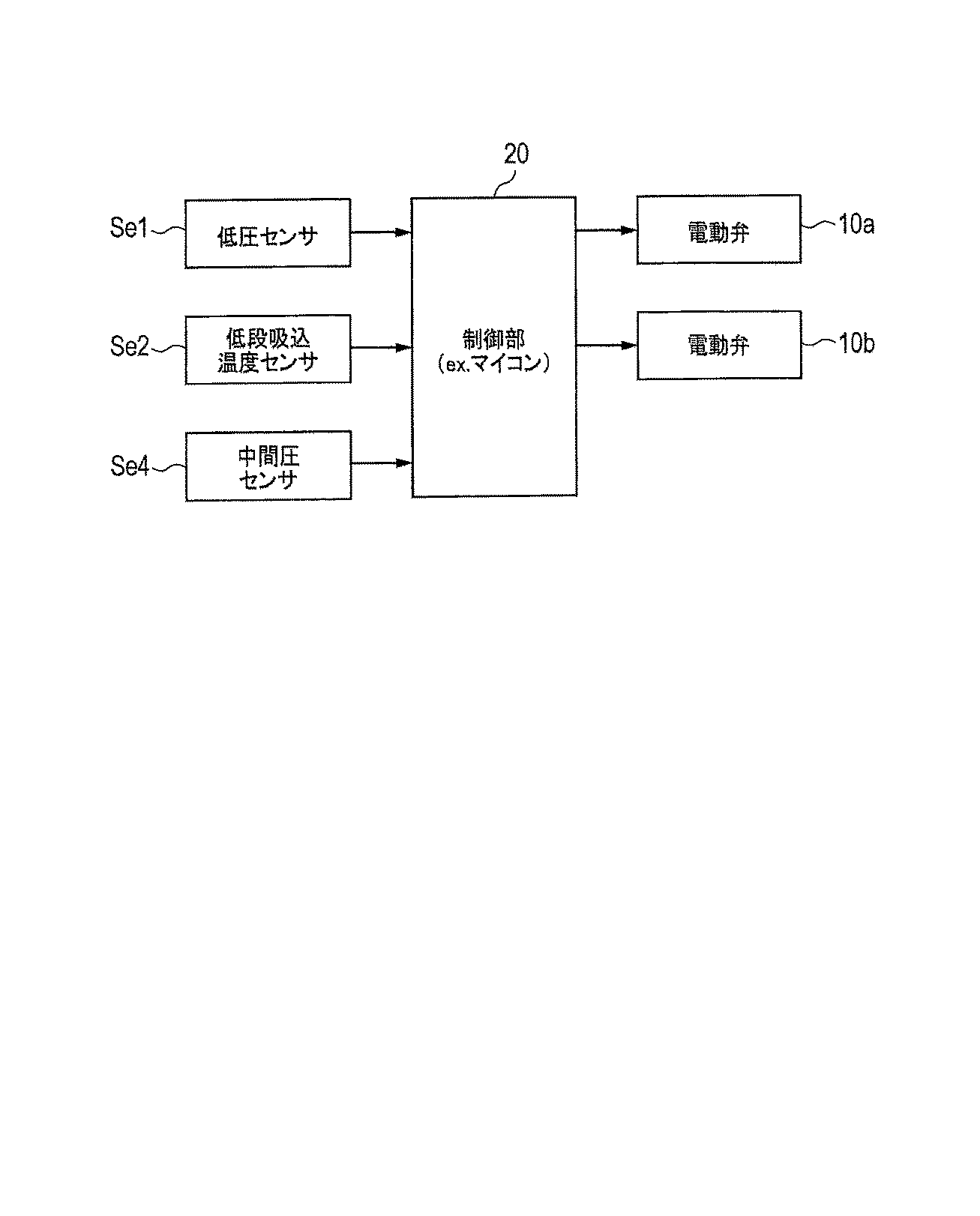
≪1−2.冷凍装置Aにおける各種センサ≫
次に、冷凍装置Aには様々な温度センサや圧力センサが設けられているが、本実施形態に係る戻し回路8の流量制御で重要となるのは、下記である。
<< 1-2. Various sensors in refrigeration equipment A >>
Next, although various temperature sensors and pressure sensors are provided in the refrigeration apparatus A, the following is important in the flow rate control of the return circuit 8 according to the present embodiment.
ガス冷媒配管P1において入口Pinから低段吸込口14a,14bまでの区間には、低圧センサSe1および低段吸込温度センサSe2が設けられる。低圧センサSe1および低段吸込温度センサSe2は、入口Pinから低段吸込口14a,14bに向かって流れる冷媒の吸込圧力および吸込温度を検出する。
A low-pressure sensor Se1 and a low-stage suction temperature sensor Se2 are provided in a section from the inlet Pin to the low-
また、ファン3やガスクーラ5を収容する筐体51の外周面には、外気温センサSe3が設けられる。外気温センサSe3は、例えばサーミスタであって、冷凍装置Aの周囲温度を外気温として検出する。
In addition, an outside air temperature sensor Se3 is provided on the outer peripheral surface of the
また、中間圧吸入管P5には中間圧センサSe4が設けられる。中間圧センサSe4は、中間圧吸入管P5を流れる冷媒の中間圧力を検出する。 An intermediate pressure sensor Se4 is provided in the intermediate pressure suction pipe P5. The intermediate pressure sensor Se4 detects the intermediate pressure of the refrigerant flowing through the intermediate pressure suction pipe P5.
≪1−3.冷凍装置Aの制御部≫
上記各センサの検出結果は、マイクロコンピュータ等を含む制御部20に出力される。制御部20は、各種センサの検出結果に基づき、圧縮機1a,1bの各モータ(図示せず)の運転周波数、各種電動弁10a,10b,61〜63の開度、ファン3の風量、ショーケース(図示せず)の電動膨張弁の開度等を制御して、これによって、ショーケース内を目標温度にする。なお、ショーケースの温度制御は周知技術で足りるため、その説明を省略する。
<< 1-3. Control unit of refrigeration apparatus A >>
The detection results of the sensors are output to the
≪1−4.技術的課題の詳細≫
従来の冷凍装置をある条件で運転させると、圧縮機の温度がカロリメータ試験で定義された基準値を超過することが判明した。具体的には、カロリメータ試験では、例えば、低段吐出口15a他の吐出温度(以下、低段吐出温度という)、圧縮機のケース温度(以下、ケース温度という)、および、圧縮機のモータに備わるコイル温度等について基準値が定義されている。しかし、外気温が高温、ショーケース側の蒸発温度が低温、かつ、冷凍装置の入口での冷媒過熱度が大きいという条件で、圧縮機を長時間連続運転すると(但し、負荷安定時)、低段吐出温度等の少なくとも一つが基準値を超えることが判明した。この理由は下記のように考えられる。
<< 1-4. Details of technical issues >>
It was found that when a conventional refrigeration system was operated under certain conditions, the compressor temperature exceeded the reference value defined in the calorimeter test. Specifically, in the calorimeter test, for example, the discharge temperature of the low-
従来の冷凍装置が上記の厳しい条件で運転しているにも関わらず、負荷が安定していると、圧縮機からのオイル持ち出し量が少なくなる。また、特許文献1の冷凍装置では、負荷安定時、戻し管に設けられた流量調整用の電動弁の開度が小さくなる。上記の要因により、オイルクーラで冷却されるオイル量(即ち、オイル循環量)が少なくなり、その結果、低段吐出温度等が高温になり過ぎると考えられる。このような問題点は、運転時の吐出オイル量が元々少ない圧縮機(所謂、低吐油タイプの圧縮機)の方が顕在化する。
Although the conventional refrigeration system is operating under the above-mentioned severe conditions, when the load is stable, the amount of oil taken out from the compressor is reduced. Further, in the refrigeration apparatus of
なお、ショーケースの扉の開閉頻度が高い場合、ショーケースの扉が長時間開放された場合、店舗屋上に設置された冷凍装置から店舗内のショーケースまでの配管長が長い場合、または、冷凍装置およびショーケース接続する配管が剥き出しの場合にも、上記と同様の理由から、圧縮機の温度(低段吐出温度、ケース温度およびコイル温度等の少なくとも一つ)が高温になり過ぎる可能性がある。 In addition, when the opening / closing frequency of the showcase door is high, when the showcase door is opened for a long time, when the piping length from the freezer installed on the store roof to the showcase in the store is long, or Even when the equipment and showcase connection pipes are exposed, the compressor temperature (at least one of the low stage discharge temperature, case temperature, coil temperature, etc.) may become too high for the same reason as above. is there.
以上の問題点に鑑み、本冷凍装置Aは、運転中、ショーケースの温度制御と並行して、下記のようなオイル戻し回路8の流量制御(第一例)を実行して、圧縮機1a,1bが高温になり過ぎることを防止している。
In view of the above problems, the refrigeration apparatus A performs the flow rate control (first example) of the oil return circuit 8 as described below in parallel with the temperature control of the showcase during operation, and the
≪1−5.オイル戻し回路8の流量制御(第一例)≫
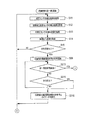
図2に示すように、本流量制御(第一例)では、制御部20は、低圧センサSe1、低段吸込温度センサSe2および外気温センサSe3の検出結果を受け取り、受け取った各検出結果に基づき、オイル戻し回路8の電動弁10a,10bの開度を制御する。以下、図3A,図3Bをさらに参照して、制御部20による流量制御(第一例)の詳細について説明する。
<< 1-5. Flow control of oil return circuit 8 (first example) >>
As shown in FIG. 2, in this flow control (first example), the
図3Aにおいて、制御部20は、例えば定期的に、低圧センサSe1,低段吸込温度センサSe2および外気温センサSe3の検出結果を取得する(ステップS01,S02,S03)。
In FIG. 3A, the
次に、制御部20は、ステップS03で得た外気温センサSe3の検出結果が所定温度以上か否かを判断する(ステップS04)。所定温度は、外気温が高いか否かを示す閾値であって、本冷凍装置Aの設計開発段階で実験等により得られる。ステップS04で所定温度以上と判断すると(即ち、YESと判断すると)、オイル戻し回路8でのオイル循環量が少ない状態になる可能性(即ち、圧縮機1a,1bが高温になり過ぎる可能性)があるとみなして、制御部20はステップS05を実行する。
Next, the
ステップS05において、制御部20は、ステップS01で得た低圧センサSe1の検出結果が所定圧力以下か否かを判断する。ここで、低圧センサSe1の検出結果は、ショーケース側の蒸発温度を実質的に一意に相関する。所定圧力は、この蒸発温度が低いか否かを示す閾値であって、本冷凍装置Aの設計開発段階で実験等により得られる。ステップS05で所定圧力以下と判断すると(即ち、YESと判断すると)、オイル循環量が少ない状態になる可能性があるとみなして、制御部20はステップS06を実行する。
In step S05, the
ステップS06において、制御部20は、ステップS01で得た低圧センサSe1の検出結果を、周知の方法で飽和温度に変換する。次に、制御部20は、ステップS02で得た検出結果とステップS06で得た飽和温度との差分値を、冷凍装置Aの入口Pinにおける過熱度として導出する(ステップS07)。次に、制御部20は、ステップS07で得た過熱度が所定過熱度以上か否かを判断する(ステップS08)。所定過熱度は、過熱度が高いか否かを示す閾値であって、本冷凍装置Aの設計開発段階で実験等により得られる。ステップS08で所定過熱度以上と判断すると(即ち、YESと判断すると)、オイル循環量が少ない状態になる可能性があるとみなして、制御部20はステップS09を実行する。
In step S06, the
ステップS09において、制御部20は、内蔵のタイマを起動して、圧縮機1a他の連続運転時間の計時を開始する。なお、本実施形態において、圧縮機1a他は、圧縮機1a,1bを意味する。次に、制御部20は、タイマによる計時開始から第一所定時間が経過したか否か(即ち、圧縮機1a他が第一所定時間だけ連続運転したか否か)を判断する(ステップS010)。第一所定時間は、オイル戻し回路8におけるオイル循環量が少ない状態に陥る程、ステップS04,S05,S08の条件を満たした状態で圧縮機1a他が連続運転したとみなせる時間であって、本冷凍装置Aの設計開発段階で実験等により得られる。第一所定時間が経過したと判断すると(即ちYESと判断すると)、圧縮機1a他が高温になり過ぎる可能性があるとみなして、制御部20は、図3BのステップS011を実行する。
In step S09, the
ステップS011において、制御部20は、電動弁10a,10bの開度を大きくして、オイル戻し回路8におけるオイル循環量を増大させる。電動弁10a,10bの開度は、例えばパルス数で定義される。この場合、ステップS011の実行前よりも多い数のパルスを電動弁10a,10bに与える。これによって、高圧のオイルセパレータ4から中間圧の圧縮機1a他へと流れるオイル量が増大する。その過程でオイルは、オイルクーラ9により冷却されるため、圧縮機1a他の各部が冷却される。
In step S011, the
ステップS011の次に、制御部20は、内蔵のタイマを起動して、電動弁10a,10bの開度を調整する時間の計時を開始する(ステップS012)。次に、制御部20は、タイマによる計時開始から第二所定時間が経過したか否かを判断する(ステップS013)。第二所定時間は、圧縮機1a他が十分に冷却されたとみなせる時間であって、カロリメータ試験等の基準値等を考慮し、本冷凍装置Aの設計開発段階で実験等により得られる。第二所定時間が経過していないと判断すると(即ちNOと判断すると)、制御部20は、ステップS012を実行する。それに対し、第二所定時間が経過したと判断すると(即ちYESと判断すると)、制御部20は、電動弁10a,10bの開度を例えばステップS011の実行前の状態に戻す(ステップS014)。
After step S011, the
再度図3Aを参照する。ステップS010において、制御部20は、第一所定時間が未経過と判断すると(即ち、NOと判断すると)、連続運転時間の計時を停止させる条件を満たしているか否かを判断する(ステップS015)。停止条件は、例えば、サーモオフや除霜運転により圧縮機1a他の運転が停止することが挙げられる。ステップS015で停止条件を満たしていないと判断すると(即ち、NOと判断すると)、制御部20は、ステップS010を再度実行する。それに対し、停止条件を満たしていると判断すると(即ち、YESと判断すると)、制御部20は、連続運転時間の計時を停止させ、タイマの初期化を行う(ステップS016)。
Refer to FIG. 3A again. In step S010, when it is determined that the first predetermined time has not elapsed (that is, when NO is determined), the
また、図3AのステップS04,S05,S08でNOと判断した場合、図3AのステップS016を実行した場合、または、図3BのステップS014を実行した場合、制御部20は、図3AのステップS01を再度実行する。
In addition, when NO is determined in steps S04, S05, and S08 in FIG. 3A, when step S016 in FIG. 3A is executed, or when step S014 in FIG. 3B is executed, the
≪1−6.流量制御(第一例)の主たる効果≫
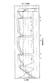
本願発明者は、本冷凍装置Aの試作機に流量制御(第一例)を実装し、効果を確認した。その結果を図4に示す。図4では、電動弁10a,10bの開度の経時変化が破線で、低段吐出口15a他での冷媒温度(即ち、低段吐出温度)の経時変化が実線で、モータ(図示せず)のコイル温度の経時変化が一点鎖線で、ケース11a他の温度(即ち、ケース温度)の経時変化が二点鎖線で示されている。電動弁10a,10bの開度は、本冷凍装置Aの運転開始直後では過渡的に大きく変動するが、負荷が安定した後は、原則として、小さく概ね一定である。そのため、低頻度ではあるが、外気温が高温、ショーケース側の蒸発温度が低温、かつ、冷凍装置Aの入口Pinでの冷媒過熱度が大きいという条件で、圧縮機1a他が長時間連続運転してしまうことがある。この時、オイル戻し回路8のオイル循環量が少ないと、図4の時間Ta,Tb,Tc等に示すように、圧縮機1a他の温度(即ち、低段吐出温度、コイル温度、ケース温度)が高温になり過ぎる。
<< 1-6. Main effects of flow control (first example) >>
The inventor of the present application mounted flow control (first example) on the prototype of the refrigeration apparatus A and confirmed the effect. The result is shown in FIG. In FIG. 4, the change with time of the opening degree of the motor-operated
本冷凍装置Aにおける流量制御(第一例)では、制御部20は、時間Ta,Tb,Tcで、オイル戻し回路8におけるオイル循環量が少ない状態にあるとみなすと、電動弁10a,10bの開度を大きくして、オイル戻し回路8におけるオイル循環量を増大させる。これによって、高圧のオイルセパレータ4から中間圧の圧縮機1a他へと流れるオイル量が増大する。その過程でオイルはオイルクーラ9により冷却されるため、圧縮機1a他の各部が冷却されて、圧縮機1a他の温度(即ち、低段吐出温度、コイル温度、ケース温度)が低下する(図4の時間Td,Te,Tfを参照)。その結果、圧縮機1a他が高温になり過ぎることが防止できて、冷凍装置Aの運転信頼性を向上することが可能となる。
In the flow rate control (first example) in the refrigeration apparatus A, when the
≪1−7.流量制御(第一例)の他の効果≫
また、制御部20は、低圧センサSe1、低段吸込温度センサSe2および外気温センサSe3の検出結果と、圧縮機1a他の連続運転時間とから、オイル循環量が少ない状態であることを定義している。それゆえ、本冷凍装置Aには、オイル戻し回路8の流量制御(第一例)のためにオイル循環量を検出するセンサを別途設けなくとも良い。さらに言えば、低圧センサSe1、低段吸込温度センサSe2および外気温センサSe3は、一般的な冷凍装置であれば、別用途のために備わっているものである。換言すると、本冷凍装置Aによれば、既存のセンサを用いて製造コストを抑えつつも、運転信頼性を向上させることが可能となる。
<< 1-7. Other effects of flow control (first example) >>
Further, the
≪1−8.流量制御(第一例)の付記≫
なお、本冷凍装置Aに備わる圧縮機の台数は二個以外であっても良いし、各圧縮機の段数は二段以上であれば良い。
<< 1-8. Additional notes on flow control (first example) >>
Note that the number of compressors provided in the refrigeration apparatus A may be other than two, and the number of stages of each compressor may be two or more.
また、流量制御(第一例)は、ステップS013に代えて、外気温センサSe3の検出結果が所定温度以上でなくなった場合、低圧センサSe1の検出結果が所定圧力以下でなくなった場合、または、過熱度が所定過熱度以上でなくなった場合に、ステップS014を実行するように変形しても構わない。 Further, in the flow control (first example), instead of step S013, when the detection result of the outside air temperature sensor Se3 is not higher than the predetermined temperature, when the detection result of the low pressure sensor Se1 is not lower than the predetermined pressure, or When the superheat degree is no longer equal to or higher than the predetermined superheat degree, it may be modified to execute step S014.
さらに、流量制御(第一例)は、ステップS015に代えて、外気温センサSe3の検出結果が所定温度以上でなくなった場合、低圧センサSe1の検出結果が所定圧力以下でなくなった場合、または、過熱度が所定過熱度以上でなくなった場合に、ステップS016を実行するように変形しても構わない。 Further, in the flow control (first example), instead of step S015, when the detection result of the outside air temperature sensor Se3 is not higher than the predetermined temperature, when the detection result of the low pressure sensor Se1 is not lower than the predetermined pressure, or If the degree of superheat is no longer equal to or greater than the predetermined degree of superheat, it may be modified to execute step S016.
また、上記では好ましい形態として、圧縮機1a他の連続運転時間が考慮されていた(図3AのステップS09等を参照)。しかし、これに限らず、ステップS08でYESと判断した直後に、ステップS011が実行されても構わない。
Further, in the above, as a preferable mode, the continuous operation time of the
≪1−9.オイル戻し回路8の流量制御(第二例)≫
上記流量制御(第一例)以外にも、制御部20は、図5に示すように、低圧センサSe1、低段吸込温度センサSe2および中間圧センサSe4の検出結果を受け取り、受け取った各検出結果に基づき、オイル戻し回路8の電動弁10a,10bの開度を制御することでも、上記流量制御(第一例)と同様の効果を得ることが出来る。以下、図6A,図6Bをさらに参照して、制御部20による流量制御(第二例)を詳説する。
<< 1-9. Flow control of oil return circuit 8 (second example) >>
In addition to the flow rate control (first example), the
図6Aにおいて、制御部20は、例えば定期的に、低圧センサSe1,低段吸込温度センサSe2および中間圧センサSe4の検出結果を取得する(ステップS11,S12,S13)。
In FIG. 6A, the
ところで、圧縮機1a他のように冷媒を断熱圧縮する場合、低段吸込口14a他での温度および圧力をT1,P1、低段吐出口15a他での温度および圧力をT2,P2とすると(図7を参照)、断熱指数をk(既知の値)とすると、次式(1)が成立する。
By the way, when the refrigerant is adiabatically compressed as in the
今、上式(1)において、低圧センサSe1の検出結果はP1に、低段吸込温度センサSe2の検出結果はT1に、中間圧センサSe4の検出結果はP2に相当する。未知数である低段吐出口15a他での温度(即ち、低段吐出温度)T2は、低圧センサSe1、低段吸込温度センサSe2、および中間圧センサSe4の検出結果を、上式(1)に代入することで導出可能である。
In the above equation (1), the detection result of the low pressure sensor Se1 corresponds to P1, the detection result of the low stage suction temperature sensor Se2 corresponds to T1, and the detection result of the intermediate pressure sensor Se4 corresponds to P2. An unknown temperature at the low-
ステップS13の次に、制御部20は、上記演算により、低段吐出温度T2を導出する(ステップS14)。制御部20は他にも、テーブル参照により低段吐出温度T2を導出することも出来る。具体的には、制御部20の不揮発性メモリには、低圧センサSe1、低段吸込温度センサSe2、および中間圧センサSe4の検出結果の組み合わせ毎に、本冷凍装置Aの設計開発段階で実験等により得た低段吐出温度T2が記述されたテーブルが格納されている。制御部20は、ステップS11,S12,S13で得た検出結果に対応する低段吐出温度T2を取得する。
After step S13, the
次に、制御部20は、ステップS14で得た低段吐出温度T2が所定温度以上か否かを判断する(ステップS15)。所定温度は、低段吐出温度T2が高いか否かを示す閾値であって、本冷凍装置Aの設計開発段階で実験等により得られる。なお、上式(1)は理想気体の断熱圧縮と仮定した場合の推定式であるため、導出した低段吐出温度T2には、理想気体と使用冷媒(CO2)との相違や使用冷媒へのオイル混入の影響等による誤差が含まれる。かかる誤差を考慮して、ステップS15で使用される所定温度は設定されることが望ましい。ステップS15で所定温度以上と判断すると(即ち、YESと判断すると)、オイル戻し回路8を循環するオイル量が少なく、圧縮機1a,1bが高温になり過ぎているとみなす。
Next, the
その後、制御部20は、ステップS09〜S016の処理を行う。ステップS09〜S016については、≪1−5.オイル戻し回路8の流量制御(第一例)≫にて詳細に説明したので、ここでは、それぞれの説明を省略する。
Thereafter, the
≪1−10.流量制御(第二例)の効果≫
本冷凍装置Aにおける流量制御(第二例)もまた、≪1−6.流量制御(第一例)の主たる効果≫で説明したのと同様の効果を奏する。
<< 1-10. Effect of flow control (second example) >>
The flow rate control (second example) in the refrigeration apparatus A is also << 1-6. The main effect of the flow rate control (first example) is the same as that described in the section >>.
また、制御部20は、低圧センサSe1、低段吸込温度センサSe2および中間圧センサSe4の検出結果と、圧縮機1a他の連続運転時間とから、圧縮機1a他の過昇温の状態にあることを推定している。それゆえ、本冷凍装置Aには、オイル戻し回路8の流量制御(第二例)のために、低段吐出温度を検出するセンサを別途設けなくとも良い。さらに言えば、低圧センサSe1、低段吸込温度センサSe2および中間圧センサSe4は、一般的な冷凍装置であれば、別用途のために備わっているものである。換言すると、本冷凍装置Aによれば、既存のセンサを用いて製造コストを抑えつつも、運転信頼性を向上させることが可能となる。
Further, the
≪1−11.流量制御(第二例)の付記≫
また、上記では好ましい形態として、圧縮機1a他の連続運転時間が考慮されていた(図6AのステップS09等を参照)。しかし、これに限らず、ステップS15でYESと判断した直後に、ステップS011が実行されても構わない。
<< 1-11. Additional notes on flow control (second example) >>
Further, in the above, as a preferable mode, the continuous operation time of the
また、流量制御(第二例)は、図6A,図6BのステップS015,S013に代えて、低段吐出温度が所定温度以上でなくなった場合に、ステップS016,S014を実行するように変形しても構わない。 Further, the flow rate control (second example) is modified to execute steps S016 and S014 when the low stage discharge temperature is not equal to or higher than the predetermined temperature instead of steps S015 and S013 in FIGS. 6A and 6B. It doesn't matter.
本発明に係る冷凍装置は、運転信頼性を向上可能であり、冷凍機システム等に好適である。 The refrigeration apparatus according to the present invention can improve the operation reliability and is suitable for a refrigerator system and the like.
A…冷凍装置
1a,1b…圧縮機
4…オイルセパレータ
8…オイル戻し回路
9…オイルクーラ
10a,10b…電動弁
20…制御部
Se1…低圧センサ
Se2…低段吸込温度センサ
Se3…外気温センサ
Se4…中間圧センサ
DESCRIPTION OF SYMBOLS A ...
Claims (9)
前記冷凍装置の入口を通じて低段吸込口から冷媒が吸入され、複数段圧縮を行って高段吐出口から冷媒を吐出する圧縮機と、
前記高段吐出口からの吐出冷媒からオイルを分離するオイルセパレータと、
前記オイルセパレータで分離されたオイルを冷却するオイルクーラと、
前記オイルクーラで冷却されたオイルを前記圧縮機に戻すオイル戻し回路と、
所定の温度情報に基づき、前記オイル戻し回路でのオイル循環量が少ない状態にあるとみなすと、前記オイル戻し回路内を流れるオイル循環量を増大させる制御部と、を備えた冷凍装置。 A refrigeration device,
A compressor that sucks refrigerant from a low-stage suction port through an inlet of the refrigeration apparatus, performs multi-stage compression, and discharges the refrigerant from a high-stage discharge port;
An oil separator that separates oil from refrigerant discharged from the high-stage discharge port;
An oil cooler for cooling the oil separated by the oil separator;
An oil return circuit for returning the oil cooled by the oil cooler to the compressor;
A refrigeration apparatus comprising: a control unit configured to increase the amount of oil circulation flowing in the oil return circuit when it is considered that the amount of oil circulation in the oil return circuit is small based on predetermined temperature information.
前記入口から前記低段吸込口に向かう冷媒の吸込圧力および温度を検出する低圧センサおよび温度センサと、をさらに備え、
前記制御部は、前記外気温センサ、前記低圧センサおよび前記温度センサの各検出結果に基づいて、前記オイル循環量が少ない状態にあるとみなす、請求項1に記載の冷凍装置。 An outside air temperature sensor for detecting outside air temperature,
A low pressure sensor and a temperature sensor for detecting the suction pressure and temperature of the refrigerant from the inlet toward the low stage suction port, and
2. The refrigeration apparatus according to claim 1, wherein the control unit considers that the oil circulation amount is in a small state based on detection results of the outside air temperature sensor, the low pressure sensor, and the temperature sensor.
前記温度センサの検出結果と、前記低圧センサの検出結果とに基づき、前記入口から前記低段吸込口に向かう冷媒の過熱度を導出し、
前記外気温センサの検出結果が所定温度以上、前記低圧センサの検出結果が所定圧力以下、かつ、導出した過熱度が所定値以上の場合に、前記オイル循環量が少ない状態にあるとみなす、請求項2に記載の冷凍装置。 The controller is
Based on the detection result of the temperature sensor and the detection result of the low-pressure sensor, the degree of superheat of the refrigerant from the inlet toward the low-stage suction port is derived,
When the detection result of the outside air temperature sensor is equal to or higher than a predetermined temperature, the detection result of the low pressure sensor is equal to or lower than a predetermined pressure, and the derived degree of superheat is equal to or higher than a predetermined value, it is considered that the oil circulation amount is small. Item 3. The refrigeration apparatus according to Item 2.
前記冷凍装置の入口を通じて低段吸込口から吸入された冷媒を圧縮して低段吐出口から吐出する圧縮機と、
前記低段吐出口からの吐出冷媒を冷却するインタークーラと、を備え、
前記圧縮機は、前記インタークーラで冷却された冷媒が高段吸込口から吸入されると、吸入冷媒を圧縮して高段吐出口から吐出し、
前記冷凍装置はさらに、
前記高段吐出口の吐出冷媒からオイルを分離するオイルセパレータと、
前記オイルセパレータで分離されたオイルを冷却するオイルクーラと、
前記オイルクーラで冷却されたオイルを前記圧縮機に戻すオイル戻し回路と、
前記低段吐出口の吐出冷媒の温度が所定温度以上であれば、前記オイル戻し回路内を流れるオイル循環を増大させる制御部と、を備える冷凍装置。 A refrigeration device,
A compressor that compresses the refrigerant sucked from the low-stage suction port through the inlet of the refrigeration apparatus and discharges the refrigerant from the low-stage discharge port;
An intercooler for cooling the refrigerant discharged from the low-stage discharge port,
When the refrigerant cooled by the intercooler is sucked from the high stage suction port, the compressor compresses the sucked refrigerant and discharges it from the high stage discharge port.
The refrigeration apparatus further includes
An oil separator that separates oil from the refrigerant discharged from the high-stage discharge port;
An oil cooler for cooling the oil separated by the oil separator;
An oil return circuit for returning the oil cooled by the oil cooler to the compressor;
A refrigeration apparatus comprising: a control unit that increases circulation of oil flowing in the oil return circuit when the temperature of refrigerant discharged from the low-stage discharge port is equal to or higher than a predetermined temperature.
前記高段吸込口に向かう冷媒の吸込圧力を検出する中間圧センサと、をさらに備え、
前記制御部は、前記低圧センサ、前記温度センサおよび前記中間圧センサの各検出結果に基づき、前記低段吐出口からの吐出冷媒の温度を推定する、請求項5に記載の冷凍装置。 A low-pressure sensor and a temperature sensor for detecting the suction pressure and temperature of the refrigerant from the inlet toward the low-stage suction port;
An intermediate pressure sensor for detecting the suction pressure of the refrigerant toward the high stage suction port,
The refrigeration apparatus according to claim 5, wherein the control unit estimates a temperature of refrigerant discharged from the low-stage discharge port based on detection results of the low-pressure sensor, the temperature sensor, and the intermediate pressure sensor.
前記制御部は、前記電動弁の開度を大きくして、前記オイル戻し回路内を流れるオイル循環量を増大させる、請求項1〜7のいずれかに記載の冷凍装置。 A motorized valve provided on the return circuit,
The refrigeration apparatus according to any one of claims 1 to 7, wherein the controller increases the amount of oil circulating through the oil return circuit by increasing an opening of the motor-operated valve.
The refrigeration apparatus according to claim 1, wherein the refrigerant is carbon dioxide.
Priority Applications (1)
| Application Number | Priority Date | Filing Date | Title |
|---|---|---|---|
| JP2016018048A JP6621017B2 (en) | 2016-02-02 | 2016-02-02 | Refrigeration equipment |
Applications Claiming Priority (1)
| Application Number | Priority Date | Filing Date | Title |
|---|---|---|---|
| JP2016018048A JP6621017B2 (en) | 2016-02-02 | 2016-02-02 | Refrigeration equipment |
Publications (2)
| Publication Number | Publication Date |
|---|---|
| JP2017138034A true JP2017138034A (en) | 2017-08-10 |
| JP6621017B2 JP6621017B2 (en) | 2019-12-18 |
Family
ID=59566844
Family Applications (1)
| Application Number | Title | Priority Date | Filing Date |
|---|---|---|---|
| JP2016018048A Active JP6621017B2 (en) | 2016-02-02 | 2016-02-02 | Refrigeration equipment |
Country Status (1)
| Country | Link |
|---|---|
| JP (1) | JP6621017B2 (en) |
Cited By (3)
| Publication number | Priority date | Publication date | Assignee | Title |
|---|---|---|---|---|
| JP2021028549A (en) * | 2019-08-09 | 2021-02-25 | ダイキン工業株式会社 | Heat source unit, and refrigeration device comprising the same |
| WO2021100234A1 (en) | 2019-11-18 | 2021-05-27 | ダイキン工業株式会社 | Intermediate unit for refrigeration device, and refrigeration device |
| CN117450693A (en) * | 2023-12-25 | 2024-01-26 | 珠海格力电器股份有限公司 | Compressor oil return control method and device, computer equipment and storage medium |
Families Citing this family (1)
| Publication number | Priority date | Publication date | Assignee | Title |
|---|---|---|---|---|
| CN111043795B (en) * | 2019-12-27 | 2021-08-20 | 广东美的白色家电技术创新中心有限公司 | Compressor assembly and refrigeration equipment |
-
2016
- 2016-02-02 JP JP2016018048A patent/JP6621017B2/en active Active
Cited By (5)
| Publication number | Priority date | Publication date | Assignee | Title |
|---|---|---|---|---|
| JP2021028549A (en) * | 2019-08-09 | 2021-02-25 | ダイキン工業株式会社 | Heat source unit, and refrigeration device comprising the same |
| JP7460877B2 (en) | 2019-08-09 | 2024-04-03 | ダイキン工業株式会社 | Heat source unit and refrigeration equipment equipped with it |
| WO2021100234A1 (en) | 2019-11-18 | 2021-05-27 | ダイキン工業株式会社 | Intermediate unit for refrigeration device, and refrigeration device |
| CN117450693A (en) * | 2023-12-25 | 2024-01-26 | 珠海格力电器股份有限公司 | Compressor oil return control method and device, computer equipment and storage medium |
| CN117450693B (en) * | 2023-12-25 | 2024-05-03 | 珠海格力电器股份有限公司 | Compressor oil return control method and device, computer equipment and storage medium |
Also Published As
| Publication number | Publication date |
|---|---|
| JP6621017B2 (en) | 2019-12-18 |
Similar Documents
| Publication | Publication Date | Title |
|---|---|---|
| EP2545331B1 (en) | Defrost operations and apparatus for a transport refrigeration system | |
| US10845096B2 (en) | Refrigeration cycle device | |
| US11454442B2 (en) | Abnormality determination device for transporting freezing device, transporting freezing device including this abnormality determination device, and abnormality determination method for transporting freezing device | |
| JP6621017B2 (en) | Refrigeration equipment | |
| EP3859249B1 (en) | Refrigerant leakage determination device, freezing device including this refrigerant leakage determination device, and refrigerant leakage determination method | |
| JP6309169B2 (en) | Air conditioner | |
| JP5759076B2 (en) | Refrigeration equipment | |
| CN109579332B (en) | Refrigeration system | |
| EP3859250B1 (en) | Abnormality determination device, freezing device including this abnormality determination device, and abnormality determination method for compressor | |
| JP2013170747A (en) | Refrigerant leakage detection device and freezing device | |
| EP2801772B1 (en) | Refrigeration device and method for detecting filling of wrong refrigerant | |
| US20230042444A1 (en) | Heat pump system and method for controlling the same | |
| JP6621275B2 (en) | Refrigeration equipment | |
| JP7280519B2 (en) | Refrigeration equipment inspection method and inspection device | |
| KR102532274B1 (en) | Air conditioner and control method | |
| JP6902729B2 (en) | Cascade refrigeration system | |
| JP2005048988A (en) | Refrigeration unit | |
| JP2005048982A (en) | Refrigeration unit | |
| JP6617862B2 (en) | refrigerator |
Legal Events
| Date | Code | Title | Description |
|---|---|---|---|
| A621 | Written request for application examination |
Free format text: JAPANESE INTERMEDIATE CODE: A621 Effective date: 20180914 |
|
| RD02 | Notification of acceptance of power of attorney |
Free format text: JAPANESE INTERMEDIATE CODE: A7422 Effective date: 20190625 |
|
| A977 | Report on retrieval |
Free format text: JAPANESE INTERMEDIATE CODE: A971007 Effective date: 20190718 |
|
| A131 | Notification of reasons for refusal |
Free format text: JAPANESE INTERMEDIATE CODE: A131 Effective date: 20190730 |
|
| A521 | Written amendment |
Free format text: JAPANESE INTERMEDIATE CODE: A523 Effective date: 20190926 |
|
| RD04 | Notification of resignation of power of attorney |
Free format text: JAPANESE INTERMEDIATE CODE: A7424 Effective date: 20191018 |
|
| TRDD | Decision of grant or rejection written | ||
| A01 | Written decision to grant a patent or to grant a registration (utility model) |
Free format text: JAPANESE INTERMEDIATE CODE: A01 Effective date: 20191105 |
|
| A61 | First payment of annual fees (during grant procedure) |
Free format text: JAPANESE INTERMEDIATE CODE: A61 Effective date: 20191108 |
|
| R150 | Certificate of patent or registration of utility model |
Ref document number: 6621017 Country of ref document: JP Free format text: JAPANESE INTERMEDIATE CODE: R150 |