JP2017137975A - Crossover joint unit - Google Patents
Crossover joint unit Download PDFInfo
- Publication number
- JP2017137975A JP2017137975A JP2016020988A JP2016020988A JP2017137975A JP 2017137975 A JP2017137975 A JP 2017137975A JP 2016020988 A JP2016020988 A JP 2016020988A JP 2016020988 A JP2016020988 A JP 2016020988A JP 2017137975 A JP2017137975 A JP 2017137975A
- Authority
- JP
- Japan
- Prior art keywords
- rod
- base
- main body
- engagement member
- base main
- Prior art date
- Legal status (The legal status is an assumption and is not a legal conclusion. Google has not performed a legal analysis and makes no representation as to the accuracy of the status listed.)
- Granted
Links
Images


Abstract
Description
本発明は、互いに交差する複数本の棒状体どうしを連結する交差連結具に関する。 The present invention relates to a cross connector for connecting a plurality of rod-shaped bodies that cross each other.
例えばケーブルラックやダクト、照明機器、空調機器の室内機等の吊設機器は、吊りボルト等の棒状体を用いて、天井スラブ等の構造体から吊設される場合がある。このような場合において、地震等に起因する吊設機器の揺れ動きを抑制するため、垂設される棒状体に対して交差姿勢で別の棒状体を配設し、これらを相互に連結して補強する場合がある。かかる目的で、第一棒状体と、この第一棒状体に対して交差する第二棒状体と、第一棒状体及び第二棒状体を包含する基準平面に対して交差する第三棒状体とを連結する交差連結具が用いられる場合がある。上述したような交差連結具の一例が、例えばネグロス電工株式会社カタログ「新発売 ガッチリロック吊りボルト振れ止め金具・全ねじ交差金具」(非特許文献1)に開示されている。 For example, suspension equipment such as cable racks, ducts, lighting equipment, and indoor units of air conditioning equipment may be suspended from structures such as ceiling slabs using rod-like bodies such as suspension bolts. In such a case, in order to suppress the swinging movement of the suspended equipment caused by an earthquake or the like, another rod-shaped body is arranged in a crossing posture with respect to the suspended rod-shaped body, and these are mutually connected to be reinforced. There is a case. For this purpose, a first rod-shaped body, a second rod-shaped body intersecting with the first rod-shaped body, a third rod-shaped body intersecting with a reference plane including the first rod-shaped body and the second rod-shaped body, In some cases, cross-connectors that connect the two are used. An example of the above-described cross connector is disclosed in, for example, a catalog “Negros Electric Works Co., Ltd.,“ New Release Gatchly Lock Suspension Bolt Stabilizer / Fully Screw Cross Metal ”(Non-Patent Document 1).
以下、非特許文献1の交差連結具を本願の図11に示し、当該図11を参照して説明する。非特許文献1の交差連結具100は、吊りボルト140を狭着するT字状の狭着部材110と、ボルト及びナットを用いて狭着部材110に連結された3つの揺動部材120とを備え、揺動部材120が支持片121と取付片122とを有するL字形に屈曲形成されている。そして、吊りボルト140に交差する3本のブレースボルト150は、取付片122の挿通孔に挿通された状態で一対のナットを用いて両側から締め付けられて、揺動部材120に固定されている。
Hereinafter, the cross connector of Non-Patent Document 1 is shown in FIG. 11 of the present application and will be described with reference to FIG. The
非特許文献1の交差連結具100では、計6ヵ所でナットの締付操作が必要であり、かつ、ブレースボルト150を固定するのに1本当たり2つのナットの締付操作が必要である。このため、1本の吊りボルト140と3本のブレースボルト150とを連結するのに多くの労力を要する。また、ブレースボルト150を取付片122に固定するには取付片122の挿通孔にブレースボルト150を挿通させる必要があるところ、例えばブレースボルト150が長い場合等にはそのような挿通操作が容易ではない場合もある。よって、この点からも、吊りボルト140とブレースボルト150とを連結するのに多くの労力を要する。
In the
第一棒状体と、この第一棒状体に対して交差する第二棒状体と、第一棒状体及び第二棒状体を包含する基準平面に対して交差する第三棒状体との連結作業を容易に行うことができる交差連結具の実現が望まれる。 Connecting the first rod-shaped body, the second rod-shaped body intersecting with the first rod-shaped body, and the third rod-shaped body intersecting with the reference plane including the first rod-shaped body and the second rod-shaped body. Realization of a cross-connector that can be easily performed is desired.
本発明に係る交差連結具は、
第一棒状体と、前記第一棒状体に対して交差する少なくとも1本の第二棒状体と、前記第一棒状体及び前記第二棒状体を包含する基準平面に対して交差する第三棒状体とを連結する交差連結具であって、
前記基準平面に沿って配置されるベース部材と、
弾性変形可能なバネ板部材で構成され、弾性復元力によって前記第一棒状体に対して係合保持される第一係合部材と、
弾性変形可能なバネ板部材で構成され、弾性復元力によって前記第二棒状体に対して係合保持される前記第二棒状体と同数の第二係合部材と、
弾性変形可能なバネ板部材で構成され、弾性復元力によって前記第三棒状体に対して係合保持される第三係合部材と、を備え、
前記ベース部材が、前記基準平面に直交する軸心周りに前記第一係合部材と前記第二係合部材とを枢支連結する第一連結部と、前記第一連結部に対して当該ベース部材の長手方向の異なる位置において前記基準平面に平行な軸心周りに前記第三係合部材を枢支連結する第二連結部とを備えているとともに、当該ベース部材の撓み変形を抑制する補強部を備えている。
The cross connector according to the present invention is
A first rod, at least one second rod intersecting the first rod, and a third rod intersecting a reference plane including the first rod and the second rod A cross-connector for connecting the body,
A base member disposed along the reference plane;
A first engagement member that is configured by an elastically deformable spring plate member and is engaged and held with respect to the first rod-like body by an elastic restoring force;
The second engagement member, which is composed of an elastically deformable spring plate member and is engaged and held with respect to the second rod-shaped body by an elastic restoring force,
A third engagement member that is configured by an elastically deformable spring plate member and is engaged and held with respect to the third rod-like body by an elastic restoring force;
A first connecting part pivotally connecting the first engaging member and the second engaging member around an axis orthogonal to the reference plane; and the base with respect to the first connecting part. And a second connecting portion for pivotally connecting the third engaging member around an axis parallel to the reference plane at different positions in the longitudinal direction of the member, and reinforcing to suppress bending deformation of the base member Department.
この構成によれば、ベース部材の第一連結部に第一係合部材と第二係合部材とが基準平面に沿って相対回転可能に連結されるとともに、ベース部材の第二連結部に第三係合部材が基準平面に交差するように相対回転可能に連結される。よって、1つのベース部材を仲介させて、互いに交差する第一棒状体と第二棒状体と第三棒状体とを、交差角度を調整しつつ連結することができる。第一係合部材、第二係合部材、及び第三係合部材はいずれも弾性変形可能なバネ板部材で構成され、弾性復元力によって対応する棒状体に対してそれぞれ係合保持されるので、各係合部材と各棒状体との係合保持操作を容易に行うことができる。よって、第一棒状体と、この第一棒状体に対して交差する第二棒状体と、第一棒状体及び第二棒状体を包含する基準平面に対して交差する第三棒状体との連結作業を容易に行うことができる。 According to this configuration, the first engagement member and the second engagement member are connected to the first connection portion of the base member so as to be relatively rotatable along the reference plane, and the second connection portion of the base member is connected to the second connection portion. The three engaging members are coupled so as to be relatively rotatable so as to intersect the reference plane. Therefore, the first rod-shaped body, the second rod-shaped body, and the third rod-shaped body that intersect with each other can be connected to each other while adjusting the intersecting angle by using one base member as an intermediary. The first engaging member, the second engaging member, and the third engaging member are all configured by elastically deformable spring plate members, and are respectively engaged and held with respect to the corresponding rod-like bodies by elastic restoring force. The engagement holding operation between each engagement member and each rod-like body can be easily performed. Therefore, the connection between the first rod-shaped body, the second rod-shaped body intersecting with the first rod-shaped body, and the third rod-shaped body intersecting with the reference plane including the first rod-shaped body and the second rod-shaped body. Work can be done easily.
ここで、上記のように第一連結部に対して長手方向の異なる位置に第二連結部が設けられる構成では、第三係合部材に対してそれに係合保持される第三棒状体からの引張力が作用したときに、ベース部材(第二連結部)に力のモーメントが作用することになる。この点、上記の構成では、ベース部材が第一連結部及び第二連結部に加えて補強部をさらに備えているので、仮にある程度の大きさの力のモーメントがベース部材(第二連結部)に作用したとしても、ベース部材の撓み変形が抑制ないし防止される。よって、各係合部材とそれぞれ対応する棒状体との間の係合保持力を高く維持することができ、例えば大きな振動等が作用するような場合にも、複数の棒状体からの離脱を有効に抑制ないし防止することができる。 Here, in the configuration in which the second connecting portion is provided at a position different in the longitudinal direction with respect to the first connecting portion as described above, from the third rod-like body engaged and held by the third engaging member. When a tensile force is applied, a moment of force is applied to the base member (second connecting portion). In this regard, in the above configuration, the base member further includes a reinforcing portion in addition to the first connecting portion and the second connecting portion, so that a moment of a certain amount of force is temporarily generated in the base member (second connecting portion). Even if it acts on, the bending deformation of the base member is suppressed or prevented. Therefore, the engagement holding force between each engagement member and the corresponding rod-like body can be maintained high. For example, even when a large vibration or the like acts, the separation from a plurality of rod-like bodies is effective. Can be suppressed or prevented.
従って、第一棒状体とそれにそれぞれ交差する第二棒状体及び第三棒状体との連結作業を容易に行うことができ、且つ、複数の棒状体に対して安定的に装着することができる交差連結具を提供することができる。 Therefore, the first rod-shaped body and the second rod-shaped body and the third rod-shaped body intersecting with the first rod-shaped body can be easily connected and can be stably attached to the plurality of rod-shaped bodies. A coupler can be provided.
以下、本発明の好適な態様について説明する。但し、以下に記載する好適な態様例によって、本発明の範囲が限定される訳ではない。 Hereinafter, preferred embodiments of the present invention will be described. However, the scope of the present invention is not limited by the preferred embodiments described below.
一態様において、
前記ベース部材が、前記第一棒状体に沿って配置される帯板状のベース本体部を備えているとともに、当該ベース本体部における一方側端部に前記第一連結部が設けられ、
前記補強部が、前記ベース本体部の長手方向における前記第一連結部よりも前記第二連結部側で、前記第一棒状体に対して前記ベース本体部とは反対側から係合作用する当接支持部で構成されていることが好ましい。
In one aspect,
The base member includes a strip-shaped base main body disposed along the first rod-shaped body, and the first connecting portion is provided at one end of the base main body,
The reinforcing portion engages with the first rod-shaped body from the side opposite to the base main body portion on the second connecting portion side with respect to the first connecting portion in the longitudinal direction of the base main body portion. It is preferable that the contact support portion is used.
この構成によれば、第三棒状体からの引張力が作用した時にベース部材(第二連結部)に作用し得る力のモーメントを、補強部を構成する当接支持部を介して、第一棒状体で受けることができる。よって、ベース部材の構造の簡単な改変によって、ベース部材の撓み変形及びそれに起因する離脱を、有効に抑制ないし防止することができる。また、第一棒状体に対してベース本体部を安定的に沿わせることができるので、第一棒状体に対するベース部材の装着姿勢を安定化させることができる。 According to this configuration, the moment of the force that can act on the base member (second connecting portion) when the tensile force from the third rod-like body acts is applied to the first via the contact support portion that constitutes the reinforcing portion. Can be received with a rod-shaped body. Therefore, by simple modification of the structure of the base member, it is possible to effectively suppress or prevent the deformation of the base member and the separation resulting therefrom. Moreover, since the base main body portion can be stably along the first rod-shaped body, the mounting posture of the base member with respect to the first rod-shaped body can be stabilized.
一態様において、
前記第一係合部材が、孔部を備えた中央板部と、前記中央板部の両端から傾斜状に延出される一対の傾斜板部とを含むとともに、一対の前記傾斜板部のそれぞれの側辺に形成された切欠状凹部によって前記第一棒状体に対して係合保持されるように構成され、
前記ベース部材が、前記当接支持部が前記第一棒状体に対して当接した状態で、前記第一棒状体に対して前記ベース本体部側から係合作用する第二当接支持部をさらに備えていることが好ましい。
In one aspect,
The first engagement member includes a central plate portion having a hole and a pair of inclined plate portions extending in an inclined manner from both ends of the central plate portion, and each of the pair of inclined plate portions. It is configured to be engaged and held with respect to the first rod-shaped body by a notch-shaped recess formed on the side,
The base member includes a second contact support portion that engages with the first rod-shaped body from the base body portion side in a state where the contact support portion is in contact with the first rod-shaped body. Furthermore, it is preferable to provide.
この構成によれば、一対の傾斜板部にそれぞれ形成された切欠状凹部に係合保持されることでベース本体部から離間して配置される第一棒状体を、第二当接支持部によって、ベース本体部側から支持することができる。当接支持部と第二当接支持部とで、ベース本体部に直交する方向における両側から第一棒状体を当接支持するので、第一棒状体に対するベース部材の装着姿勢をより一層安定化させることができる。 According to this configuration, the first rod-like body disposed away from the base main body portion by being engaged and held in the notch-like concave portions formed in the pair of inclined plate portions is provided by the second contact support portion. It can be supported from the base body side. Since the first rod-shaped body is abutted and supported from both sides in the direction orthogonal to the base body portion by the abutment support portion and the second contact support portion, the mounting posture of the base member to the first rod-shaped body is further stabilized. Can be made.
一態様において、
前記当接支持部が、前記ベース本体部と一体のL字状の屈曲片で構成され、
前記第一係合部材が、前記バネ板部材の側辺に形成された一対の切欠状凹部によって前記第一棒状体に対して係合保持されるように構成されているとともに、前記ベース部材に対して相対回転が規制された状態で連結され、
前記ベース本体部と前記屈曲片とによって区画される空間が、一対の前記切欠状凹部と前記第一棒状体とが係合する際の前記ベース部材に対する前記第一棒状体の相対近接移動を迎え入れる向きに開口していることが好ましい。
In one aspect,
The abutting support part is configured by an L-shaped bent piece integral with the base body part,
The first engagement member is configured to be engaged and held with respect to the first rod-like body by a pair of notch-shaped recesses formed on the side of the spring plate member, and the base member In contrast, the relative rotation is restricted and connected.
The space defined by the base main body and the bent piece welcomes relative movement of the first rod-like body with respect to the base member when the pair of notched recesses and the first rod-like body are engaged. It is preferable to open in the direction.
この構成によれば、例えば1枚の金属板からベース本体部の元となる部分と屈曲片の元となる部分とを一体的に打ち抜き形成した後、屈曲片の元となる部分を屈曲操作するだけで、屈曲片からなる当接支持部を、容易に、ベース部材に設けることができる。屈曲片の開口向きを上記のように設定することで、一対の切欠状凹部と第一棒状体とを係合させて第一棒状体に第一係合部材を係合保持させるのに伴って、自ずと、当接支持部がベース本体部とは反対側から第一棒状体に対して係合作用する状態となる。よって、第一棒状体に第一係合部材を係合保持させるための操作とベース部材に追加的に設けられる当接支持部で第一棒状体を当接支持するための操作とを同時に行うことができ、施工性を向上させることができる。 According to this configuration, for example, the base portion of the base body and the base portion of the bent piece are integrally punched from one metal plate, and then the base portion of the bent piece is bent. Only, the contact support part which consists of a bending piece can be provided in a base member easily. By setting the opening direction of the bent piece as described above, the pair of notch-shaped recesses and the first rod-shaped body are engaged, and the first engagement member is engaged and held by the first rod-shaped body. As a matter of course, the contact support portion engages with the first rod-shaped body from the side opposite to the base main body portion. Therefore, an operation for engaging and holding the first engagement member on the first rod-shaped body and an operation for abutting and supporting the first rod-shaped body at the contact support portion additionally provided on the base member are simultaneously performed. It is possible to improve the workability.
一態様において、
前記ベース部材が、前記第一棒状体に沿って配置される帯板状のベース本体部を備えているとともに、当該ベース本体部に前記第一連結部が設けられ、
前記ベース本体部における前記第一連結部が設けられた部分に、前記ベース本体部から突出して前記第一係合部材の両側端面に係止される一対の突出片が設けられていることが好ましい。
In one aspect,
The base member is provided with a strip-like base main body portion arranged along the first rod-shaped body, and the first connecting portion is provided in the base main body portion,
It is preferable that a pair of protruding pieces that protrude from the base main body portion and are engaged with both side end surfaces of the first engaging member are provided in a portion of the base main body portion where the first connecting portion is provided. .
この構成によれば、一対の突出片が第一係合部材の両側端面に係止された状態で、ベース本体部に対する第一係合部材の相対回転を規制することができる。よって、第一棒状体に対してベース本体部を安定的に沿わせることができる。また、ベース本体部から突出する一対の突出片の存在は、第一連結部における第一係合部材の取付部位や、第一棒状体に対して係合保持させるべき第一係合部材を明示する機能を発揮する。よって、交差連結具の組立時におけるベース部材の適正位置への第一係合部材の取り付けや、施工時における第一棒状体への適正姿勢での取り付けの容易化を図ることができる。 According to this configuration, relative rotation of the first engagement member with respect to the base main body portion can be restricted in a state where the pair of protruding pieces are locked to both end surfaces of the first engagement member. Therefore, the base main body can be stably along the first rod-shaped body. Further, the presence of the pair of projecting pieces projecting from the base main body clearly indicates the first engagement member mounting portion and the first engagement member to be engaged and held with respect to the first rod-shaped body. Demonstrate the function to do. Therefore, it is possible to facilitate the attachment of the first engagement member to the appropriate position of the base member at the time of assembly of the cross connector and the attachment in the appropriate posture to the first rod-like body at the time of construction.
一態様において、
前記ベース部材が、前記第一棒状体に沿って配置される帯板状のベース本体部と、前記ベース本体部から交差姿勢で延出し且つ当該ベース本体部と一体の延出板部とを備え、
前記ベース本体部に前記第一連結部が設けられているとともに、前記延出板部に前記第二連結部が設けられ、
前記第一連結部において、前記ベース本体部の両面側に分かれて前記第一係合部材と前記第二係合部材とが枢支連結され、
前記第二連結部において、前記延出板部の屈曲外面側に前記第三係合部材が枢支連結されていることが好ましい。
In one aspect,
The base member includes a strip-like base main body disposed along the first rod-like body, and an extending plate that extends from the base main body in a crossing posture and is integral with the base main body. ,
The first connecting part is provided in the base body part, and the second connecting part is provided in the extending plate part,
In the first connection part, the first engagement member and the second engagement member are pivotally connected to each other on both sides of the base body part,
In the second connection portion, it is preferable that the third engagement member is pivotally connected to the bent outer surface side of the extension plate portion.
この構成によれば、第二係合部材や第三係合部材が他の要素と干渉することなく回転自在となるので、第一棒状体に対する第二棒状体や第三棒状体の交差角度を、様々な角度に調整することができる。よって、第一棒状体とそれにそれぞれ交差する第二棒状体及び第三棒状体とを連結し、且つ、様々な交差角度に対応可能な交差連結具を提供することができる。 According to this configuration, since the second engagement member and the third engagement member can rotate without interfering with other elements, the crossing angle of the second rod body or the third rod body with respect to the first rod body is set. Can be adjusted to various angles. Therefore, it is possible to provide a cross connector that connects the first rod-shaped body and the second rod-shaped body and the third rod-shaped body that intersect with the first rod-shaped body, and can cope with various crossing angles.
一態様において、
前記第一連結部において、前記第一係合部材と前記第二係合部材とが、前記基準平面に直交する単一の軸心周りに共通に枢支連結されていることが好ましい。
In one aspect,
In the first connecting portion, it is preferable that the first engaging member and the second engaging member are pivotally connected in common around a single axis perpendicular to the reference plane.
この構成によれば、第一棒状体及び第二棒状体のそれぞれの重心位置が一致するので、例えばそれらが偏心する場合に比べて、より良好な振れ止め効果を得ることができる。また、第一連結部をコンパクトに構成することができ、例えば第一係合部材と第二係合部材とが第一連結部において別々に枢支連結される構成に比べて、ベース部材ひいては交差連結具の小型化を図ることができる。さらに、第一係合部材を枢支連結するための部材と第二係合部材を枢支連結するための部材とを兼用させることができるので、部品点数を少なく抑えて低コスト化を図ることができる。 According to this configuration, since the respective barycentric positions of the first rod-like body and the second rod-like body coincide with each other, a better steadying effect can be obtained as compared with a case where they are eccentric, for example. In addition, the first connecting portion can be configured in a compact manner. For example, the first connecting member and the second engaging member are pivotally connected separately at the first connecting portion, so that the base member and thus the intersection are crossed. The connector can be downsized. Furthermore, since the member for pivotally connecting the first engagement member and the member for pivotally connecting the second engagement member can be used together, the number of parts can be reduced and the cost can be reduced. Can do.
本発明のさらなる特徴と利点は、図面を参照して記述する以下の例示的かつ非限定的な実施形態の説明によってより明確になるであろう。 Further features and advantages of the present invention will become more apparent from the following description of exemplary and non-limiting embodiments described with reference to the drawings.
交差連結具の実施形態について、図面を参照して説明する。本実施形態に係る交差連結具1は、吊りボルト81(棒状体の一例)と、この吊りボルト81に対してそれぞれ交差する3本のブレースボルト82(棒状体の他の一例)とを連結するための器具(棒状体用交差連結具)である。具体的には、交差連結具1は、吊りボルト81と、吊りボルト81に対して交差する少なくとも1本のブレースボルト82Aと、吊りボルト81及びブレースボルト82Aを包含する基準平面Pに対して交差するブレースボルト82Bとを連結するための器具である。
An embodiment of a cross connector will be described with reference to the drawings. The cross connector 1 according to the present embodiment connects a suspension bolt 81 (an example of a rod-shaped body) and three brace bolts 82 (another example of a rod-shaped body) that intersect the
本実施形態の交差連結具1は、第1に、以下の点によって特徴付けられる。すなわち、交差連結具1は、基準平面Pに沿って配置されるベース部材20と、吊りボルト81に対して係合保持される第一係合部材30と、ブレースボルト82Aに対して係合保持されるブレースボルト82Aと同数の第二係合部材40と、ブレースボルト82Bに対して係合保持される第三係合部材50とを備えている。各係合部材30,40,50は、弾性変形可能なバネ板部材で構成されており、弾性復元力によってそれぞれ対応するボルト81,82A,82Bに係合保持される。そして、ベース部材20が、基準平面Pに直交する軸心周りに第一係合部材30と第二係合部材40とを枢支連結する第一連結部22と、第一連結部22に対して当該ベース部材20の長手方向Lの異なる位置において基準平面Pに平行な軸心周りに第三係合部材50を枢支連結する第二連結部25とを備えている。これにより、吊りボルト81と、この吊りボルト81に対して交差するブレースボルト82Aと、吊りボルト81及びブレースボルト82Aを包含する基準平面Pに対して交差するブレースボルト82Bとの連結作業を容易に行うことができる。
The cross connector 1 of this embodiment is first characterized by the following points. That is, the cross connector 1 is engaged and held with respect to the
また、本実施形態の交差連結具1は、第2に、ベース部材20が、当該ベース部材20の撓み変形を抑制する補強部26をさらに備えている点によって特徴付けられる。これにより、各係合部材30,40,50とそれぞれ対応するボルト81,82A,82Bとの間の係合保持力を高く維持することができ、例えば大きな振動等が作用するような場合にも、交差連結具1の離脱を有効に抑制ないし防止することができる。以下、本実施形態の交差連結具1について、詳細に説明する。
Secondly, the cross connector 1 of the present embodiment is characterized in that the
図1に、例えばコンクリート製の天井スラブや梁等の構造体から垂設された複数の吊りボルト(棒状体の一例)81を用いて、天井付近に吊設部材9を支持する支持構造を示す。吊設部材9は、例えばケーブルラックやダクト、照明機器、空調機器の室内機等である。本実施形態では、天井スラブから垂設された吊りボルト81を用いて、ケーブルラック90(吊設部材9の一例)が支持された構造を例として説明する。本支持構造は、一例として、ケーブルラック90の配設方向Aに沿う複数箇所に、構造体から左右一対の吊りボルト81が垂設され、当該左右一対の吊りボルト81に亘って連結される支持枠体95によって、ケーブルラック90が下方から支持されてなる。
FIG. 1 shows a support structure for supporting a
本実施形態では、それぞれの吊りボルト81に対して、3本のブレースボルト82が交差する姿勢で配置されている。これらのうち、2本のブレースボルト82は、鉛直方向に対して、ケーブルラック90の配設方向Aに沿って傾斜する姿勢で配置されている。この2本のブレースボルト82は、吊りボルト81と共に、ケーブルラック90の配設方向Aに沿う鉛直平面に沿って配置されている。これら2本のブレースボルト82と吊りボルト81とを包含する鉛直平面を、本実施形態では「基準平面P」と定義する。なお、吊りボルト81と2本のブレースボルト82とは互いに干渉することなく配置されるので、これらを包含する「基準平面P」は、ある程度の厚みを有するものとして観念される(図6を参照)。本実施形態では、基準平面Pに沿って当該基準平面Pと平行に配置されるブレースボルト(平行ブレースボルト)82を、「ブレースボルト82A」と表記する。
In the present embodiment, three
一方、3本のブレースボルト82のうち、残余の1本のブレースボルト82は、鉛直方向に対して、ケーブルラック90の配設方向Aに直交する直交方向Bに沿って傾斜する姿勢で配置されている。このブレースボルト82は、基準平面Pには包含されることなく当該基準平面Pに対して交差している。本実施形態では、基準平面Pに交差しつつ直交方向Bに沿って配置されるブレースボルト(交差ブレースボルト)82を、「ブレースボルト82B」と表記する。本実施形態では、吊りボルト81が「第一棒状体」に相当し、ブレースボルト82Aが「第二棒状体」に相当し、ブレースボルト82Bが「第三棒状体」に相当する。
On the other hand, of the three
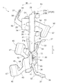
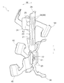
吊りボルト81と3本のブレースボルト82とを連結する交差連結具1は、図2〜図4に示すように、ベース部材20と、第一係合部材30と、本実施形態では2つの第二係合部材40と、第三係合部材50とを備えている。
As shown in FIGS. 2 to 4, the cross connector 1 that connects the
ベース部材20は、第一係合部材30、第二係合部材40、及び第三係合部材50を互いに連結するためのベースとなる部材である。ベース部材20は、鉄やステンレス、炭素鋼等の金属材料を用いて構成されている。ベース部材20は、各係合部材30,40,50に比べて肉厚の金属板で構成されており、各係合部材30,40,50に比べて高い剛性を有している。ベース部材20は、基準平面Pに沿って配置される。ベース部材20は、ベース本体部21と、当該ベース本体部21と一体の延出板部24とを備えている。また、ベース部材20は、突出片23と、補強部26としての第一当接支持部27と、第二当接支持部29とをさらに備えている。
The
ベース本体部21は、帯板状に形成されている。ベース本体部21は、その長手方向Lの長さが幅方向Wの長さに比べて十分に長い(例えば3倍以上の)帯板状に形成されている。このベース本体部21における長手方向Lの一方側端部に、第一連結部22が設けられている。第一連結部22は、基準平面Pに直交する軸心周りに第一係合部材30と第二係合部材40とを枢支連結する部位である。本実施形態では、第一連結部22において、第一係合部材30と第二係合部材40とが、基準平面Pに直交する単一の第一軸心X1周りに共通に枢支連結されている。
The base
本実施形態では、第一連結部22において、ベース本体部21の両面側に分かれて第一係合部材30と第二係合部材40とが枢支連結されている。本実施形態では、ベース本体部21における第一連結部22が設けられた部分の側辺に、ベース本体部21から突出する一対の突出片23が設けられている。一対の突出片23は、ベース本体部21における第一連結部22が設けられた部分の幅方向Wの両側に、ベース本体部21に対して直交する状態に配置されている。そして、ベース本体部21における突出片23が突出する側の面(以下、“突出側面21p”と言う。)に第一係合部材30が配置され、それとは反対側の面(以下、“反突出側面21q”と言う。)に2つの第二係合部材40が重ねて配置されている。2つの第二係合部材40は同じ向きとなるように入れ子状に重ねて配置されているとともに、第一係合部材30と2つの第二係合部材40とは、互いに反対向きとなるように、ベース本体部21を挟んで背中合わせ状に配置されている。
In this embodiment, in the
図4に示すように、ベース部材20(具体的にはベース本体部21)の第一連結部22には、ベース本体部21を厚み方向に貫通する挿通孔21aが形成されている。この挿通孔21aには、第一係合部材30の中央板部31の孔部31aと第二係合部材40の中央板部41の孔部41aとをさらに重ねた状態で、例えばリベット等の枢支連結部材61が挿通される。こうして、ベース部材20(ベース本体部21)の第一連結部22に対して、3つの係合部材30,40,40が、枢支連結部材61により、積層状態で枢支連結されている。
As shown in FIG. 4, an
このとき、第一係合部材30は、図2に示すようにその両側端面が一対の突出片23に係止された状態となっており、一対の突出片23により、ベース部材20(ベース本体部21)に対して相対回転が規制された状態で連結されている。一対の突出片23は、ベース部材20に対する第一係合部材30の相対回転を規制する回転規制手段として機能する。第一係合部材30は、それに係合保持される吊りボルト81の軸方向とベース部材20(ベース本体部21)の長手方向Lとが実質的に同方向となる向きに回転規制される。これにより、交差連結具1の装着状態において、ベース本体部21は常に吊りボルト81に沿って配置されることになる。一方、ベース本体部21の反突出側面21qに配置される2つの第二係合部材40は、その周囲に干渉する要素が存在しておらず、ベース部材20及び第一係合部材30に対して、それぞれ独立に、相対回転自在となっている(図3を参照)。よって、吊りボルト81に対する2本のブレースボルト82Aのそれぞれの交差角度を、任意の角度に調整することが可能となっている。
At this time, as shown in FIG. 2, the
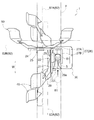
延出板部24は、ベース本体部21と一体に形成されているとともに、ベース本体部21の側辺から交差姿勢で延出している。延出板部24は、ベース本体部21から突出片23が突出する向きとは反対向きに延出している。また、延出板部24は、ベース部材20における第一連結部22とは異なる長手方向Lの位置に設けられており、より具体的にはベース部材20における第一連結部22とは長手方向Lの反対側の部位に設けられている。第二連結部25は、第一係合部材30や第二係合部材40と第三係合部材50とが干渉しないように、第一連結部22から長手方向Lに沿って例えば第一係合部材30の長さ分以上離れた位置に設けられている。
The
延出板部24は、正方形又はそれに近い形状の帯板状に形成されている。本実施形態では、延出板部24は、ベース本体部21に対して直交する姿勢で配置されている。この延出板部24に、第二連結部25が設けられている。第二連結部25は、基準平面Pに平行な軸心周りに第三係合部材50を枢支連結する部位である。第二連結部25において、第三係合部材50が、基準平面Pに平行であり(第一軸心X1に直交し)、且つ、ケーブルラック90の配設方向Aに沿う第二軸心X2周りに枢支連結されている。本実施形態では、第二連結部25において、延出板部24の屈曲外面側に第三係合部材50が枢支連結されている。すなわち、延出板部24におけるベース本体部21の突出側面21pから連なる面に、第三係合部材50が枢支連結されている。
The
図4に示すように、ベース部材20(具体的には延出板部24)の第二連結部25には、延出板部24を厚み方向に貫通する挿通孔24aが形成されている。この挿通孔24aには、第三係合部材50の中央板部51の孔部51aをさらに重ねた状態で、例えばリベット等の枢支連結部材62が挿通される。こうして、ベース部材20(延出板部24)の第二連結部25に対して、1つの第三係合部材50が、枢支連結部材62によって枢支連結されている。このとき、延出板部24の屈曲外面側に配置される第三係合部材50は、その周囲に干渉する要素が存在しておらず、ベース部材20及び第一係合部材30に対して、相対回転自在となっている(図3を参照)。よって、吊りボルト81に対するブレースボルト82Bの交差角度を、任意の角度に調整することが可能となっている。
As shown in FIG. 4, an
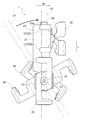
図2〜図4に示すように、第一係合部材30は、弾性変形可能な帯板状のバネ板部材で構成されている。第一係合部材30は、中央板部31と、傾斜板部33と、操作板部37とを含んでいる。中央板部31は、ベース部材20への取付基部となる平坦な板状部である。中央板部31の中央部には、枢支連結部材61が挿通される孔部31aが形成されている。傾斜板部33は、中央板部31の両端に一対設けられている。一対の傾斜板部33は、中央板部31の両端からそれぞれ傾斜状に延出されている。操作板部37は、各傾斜板部33の外側(中央板部31とは反対側)の端部にそれぞれ設けられている。一対の操作板部37は、それぞれ、対応する傾斜板部33の外側の端部から、中央板部31に対する傾斜板部33の傾斜角度とは異なる角度で、さらに傾斜状に延出されている。
As shown in FIGS. 2 to 4, the
一対の傾斜板部33のそれぞれの側辺には、切欠状凹部34が形成されている。切欠状凹部34は、その切り欠かれた部分の概略形状がU字状を呈するように形成されている。なお、切欠状凹部34のうち、傾斜板部33の側辺に連なる境界部分は、傾斜板部33の側辺に近づくに従って切欠幅が幅広となるテーパ状に形成されている。本実施形態では、各傾斜板部33にそれぞれ形成されて対をなす2つの切欠状凹部34は、互いに逆方向を向くように形成されている。すなわち、一対の切欠状凹部34は、第一係合部材30を構成するバネ板部材の互いに異なる側辺に分かれて形成されている。これら一対の切欠状凹部34によって、吊りボルト81に対して第一係合部材30が係合保持される(図2を参照)。
A notch-shaped
係合保持操作は、以下のようにして行うことができる。すなわち、まず、垂設される吊りボルト81に対して、第一係合部材30を、その一対の切欠状凹部34のそれぞれの開口が対向する状態に配置する。このとき、第一係合部材30の長手方向は、吊りボルト81の軸方向に対して交差した状態となっている。次に、第一係合部材30の両端の操作板部37を互いに近接させるように摘み操作して、一対の切欠状凹部34に亘って吊りボルト81が係入可能な状態となるまで、第一係合部材30を弾性変形させる。この状態で、垂設される吊りボルト81に対して第一係合部材30を回転操作して(第一係合部材30に対して吊りボルト81を相対回転させて)、実際に一対の切欠状凹部34に亘って吊りボルト81を係入させる(図7を参照)。その後、一対の操作板部37を摘み操作していた力を解除すれば、バネ板部材の弾性復元力で、一対の切欠状凹部34によって第一係合部材30を吊りボルト81に係合保持させることができる。
The engagement holding operation can be performed as follows. That is, first, the
なお、傾斜板部33における各切欠状凹部34の外側且つ開口側の端縁に沿って、鋭角三角形状の係止爪35が、傾斜板部33の延在面に対して交差する状態に設けられている。この係止爪35は、一対の切欠状凹部34に係入した吊りボルト81に係止されることにより、当該吊りボルト81の切欠状凹部34の開口側への抜け出し移動を阻止する抜止手段として機能する。
In addition, along the edge on the opening side of each notch-shaped
第二係合部材40は、第一係合部材30と同様の基本構成を備えている。すなわち、第二係合部材40は、弾性変形可能な帯板状のバネ板部材で構成されている。また、第二係合部材40は、孔部41aを備えた中央板部41と、切欠状凹部44及び係止爪45を備えた一対の傾斜板部43と、一対の操作板部47とを備えている。第二係合部材40は、第一連結部22において、第一係合部材30と共に枢支連結されている。第二係合部材40は、一対の切欠状凹部44によって、ブレースボルト82Aに対して係合保持される。なお、重ねて配置される2つの第二係合部材40は、係合保持対象の2本のブレースボルト82Aどうしの干渉を回避するべく、それぞれにおける一対の切欠状凹部44どうしの間の間隔が互いに異なるように、異なる長さに形成されている(図7を参照)。
The
第三係合部材50も、第一係合部材30及び第二係合部材40と同様の基本構成を備えている。すなわち、第三係合部材50は、弾性変形可能な帯板状のバネ板部材で構成されている。また、第三係合部材50は、孔部51aを備えた中央板部51と、切欠状凹部54及び係止爪55を備えた一対の傾斜板部53と、一対の操作板部57とを備えている。第三係合部材50は、第二連結部25において枢支連結されている。第三係合部材50は、一対の切欠状凹部54によって、ブレースボルト82Bに対して係合保持される。
The
本実施形態の交差連結具1では、ベース部材20の第一連結部22に第一係合部材30と2つの第二係合部材40とが基準平面Pに沿って相対回転可能に連結されるとともに、第二連結部25に第三係合部材50が基準平面Pに交差するように相対回転可能に連結される。よって、1つのベース部材20を仲介させて、互いに交差する1本の吊りボルト81と2本のブレースボルト82Aと1本のブレースボルト82Bとを、交差角度を調整しつつ連結することができる。このとき、第一係合部材30や第二係合部材40と第三係合部材50とが干渉しないように、第一連結部22に対して長手方向Lの異なる位置に第二連結部25が設けられるので、吊りボルト81及びブレースボルト82Aを包含する基準平面Pに対するブレースボルト82Bの交差角度を任意に設定することができる。
In the cross connector 1 of the present embodiment, the
第一係合部材30、第二係合部材40、及び第三係合部材50はいずれも弾性変形可能なバネ板部材で構成され、弾性復元力によって対応するボルト81,82A,82Bに対してそれぞれ係合保持されるので、各係合部材30,40,50と各ボルト81,82A,82Bとの係合保持操作を容易に行うことができる。すなわち、“係合部材を構成するバネ板部材の弾性変形→ボルトに対する係合部材の相対近接移動→弾性復元力による係合保持”の一連の操作を4回繰り返すだけで、各係合部材30,40,50と各ボルト81,82A,82Bとの係合保持操作を容易に行うことができる。よって、吊りボルト81と、基準平面P内で吊りボルト81に交差するブレースボルト82Aと、基準平面Pに交差するブレースボルト82Bとの連結作業を容易に行うことができる。
The
ここで、上記のように第一連結部22に対して長手方向Lの異なる位置に第二連結部25が設けられる構成では、第三係合部材50に対してブレースボルト82Bからの引張力が作用したときに、ベース部材20(具体的には第二連結部25)に力のモーメントが作用することになる。第二連結部25は、第一係合部材30や第二係合部材40と第三係合部材50とが干渉しない程度に長手方向Lに沿って第一連結部22から離間して設けられるので、作用する力のモーメントは特に大きくなりやすい。このような力のモーメントがベース部材20(第二連結部25)に作用すると、第一連結部22を支点として第二連結部25が反突出側面21q側(突出片23が突出する側とは反対側)に変位する態様で、ベース部材20が撓み変形してしまう。ベース部材20に撓み変形が生じると、少なくとも1組の係合部材30,40,50と対応するボルト81,82A,82Bとの係合保持力が低下してしまい、場合によっては離脱してしまう可能性がある。
Here, in the configuration in which the second connecting
そこで、本実施形態の交差連結具1では、ベース部材20が、第一連結部22を有するベース本体部21と第二連結部25を有する延出板部24とに加え、補強部26をさらに備えている。補強部26は、ベース部材20の撓み変形を抑制する機能を果たす部位である。補強部26は、それ自体に内在する特性(例えば剛性や強度等)によってベース部材20の撓み変形を抑制するものであっても良いし、周囲に存在する他の部材との協働によってベース部材20の撓み変形を抑制するものであっても良い。また、補強部26は、ベース本体部21と一体に形成されていても良いし、ベース本体部21に固定されて用いられる、別部材からなる補強部材であっても良い。
Therefore, in the cross connector 1 of the present embodiment, the
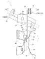
本実施形態の補強部26は、ベース本体部21と一体に形成され、且つ、ベース本体部21の長手方向Lにおける第一連結部22よりも第二連結部25側で、吊りボルト81に対してベース本体部21とは反対側から係合作用する第一当接支持部27で構成されている。本実施形態では、第一当接支持部27が「当接支持部」に相当する。より具体的には、補強部26としての第一当接支持部27は、ベース本体部21の側辺から延出するように形成された、ベース本体部21と一体のL字状の屈曲片で構成されている。第一当接支持部27は、ベース本体部21に交差(本例では直交)する支持板部27Aと、支持板部27Aの先端部からベース本体部21に平行状に延びる当接板部27Bとを含む。支持板部27Aは、ベース本体部21から突出片23と同じ向き(延出板部24とは反対向き)に延出するように配置されている。
The reinforcing
ベース本体部21からの支持板部27Aの延出長さは、ベース本体部21と吊りボルト81との離間長さと吊りボルト81の直径との和に等しいか、それよりも僅かに長く設定されている。このため、当接板部27Bは、図5及び図6に示すように、第一係合部材30に係合保持された吊りボルト81に対して、ベース本体部21から見て背面側から吊りボルト81に当接する。なお、「当接する」とは、常時当接する態様以外にも、要時に速やかに当接可能な態様(例えば、僅かなクリアランスが設けられている場合において、相対近接移動によって速やかに当接する態様)をも含む概念である。
The extension length of the
また、本実施形態では、ベース部材20は、補強部26として、ベース本体部21における長手方向Lの異なる位置に設けられた複数の第一当接支持部27を備えている。本実施形態では、ベース本体部21における長手方向Lの第一連結部22とは反対側の端部に第1の第一当接支持部27が設けられ、延出板部24に対して第1の第一当接支持部27とは反対側となる長手方向Lの位置に、第2の第一当接支持部27が設けられている。
In the present embodiment, the
このように一対の第一当接支持部27を備えることで、ブレースボルト82Bからの引張力が作用した時にベース部材20(具体的には第二連結部25)に作用し得る力のモーメントを、吊りボルト81の軸方向の異なる2箇所に分散させて受けることができる。このため、仮に比較的大きな力のモーメントがベース部材20(第二連結部25)に作用したとしても、ベース部材20の撓み変形が有効に抑制ないし防止される。よって、係合部材30,40,50と対応するボルト81,82A,82Bとの係合保持力を高く維持することができ、例えば大きな振動等が作用するような場合にも、ボルト81,82A,82Bの離脱を有効に抑制ないし防止することができる。しかも、ベース部材20の構造の簡単な改変によって低コストに、かかる効果を得ることができる。
By providing the pair of first
本実施形態では、ベース部材20が、補強部26としての第一当接支持部27に加え、第一当接支持部27が吊りボルト81に対して当接した状態で、ベース本体部21側から吊りボルト81に対して係合作用する第二当接支持部29をさらに備えている。第二当接支持部29は、ベース本体部21における第一連結部22とは反対側の端部において、ベース本体部21と一体に形成されている。第二当接支持部29は、矩形状に形成されている。第二当接支持部29は、ベース本体部21に対して交差し(本例ではおよそ45°傾斜し)、且つ、ベース本体部21の長手方向Lに沿って延出するように配置されている。図5及び図6に示すように、第二当接支持部29は、第一係合部材30の傾斜板部33に形成された切欠状凹部34に係合保持されることによってベース本体部21からその厚み方向に離間して配置される吊りボルト81を、ベース本体部21側から支持する。このような第二当接支持部29をさらに備えることで、第一当接支持部27と第二当接支持部29とで、ベース本体部21に直交する方向における両側から吊りボルト81を支持することができる。よって、吊りボルト81に対するベース部材20の装着姿勢を安定化させることができる。
In the present embodiment, the
上述したように、本実施形態では、第一係合部材30がベース部材20に対して相対回転が規制された状態で連結されている。このため、吊りボルト81に対して第一係合部材30を係合保持させる際には、第一係合部材30の回転操作に伴い、ベース部材20もが吊りボルト81側に向かって近接移動する。そこで本実施形態では、ベース本体部21と第一当接支持部27とによって区画される空間Sが、一対の切欠状凹部34に吊りボルト81を係合させる際のベース部材20に対する吊りボルト81の相対近接移動を迎え入れる向きに開口するように、L字状の屈曲片からなる第一当接支持部27の向きが設定されている(図6及び図7を参照)。なお、図7では、交差連結具1側から見た吊りボルト81の相対近接移動(本例では相対回転)の様子を示している。かかる構成により、吊りボルト81に第一係合部材30を係合保持させるための操作と、ベース部材20に追加的に設けられる第一当接支持部27で吊りボルト81を当接支持するための操作とを同時に行うことができる。よって、施工性を向上させることができる。
As described above, in the present embodiment, the
また、本実施形態では、図6に示すように、矩形状の第二当接支持部29における第一当接支持部27の開口側の角部は、第一当接支持部27の奥側(支持板部27A側)の角部に比べてより大きく丸み付けられている。第二当接支持部29の当該開口側の角部の表面は、ベース部材20に対する吊りボルト81の相対近接移動を迎え入れる際に、第一当接支持部27と第二当接支持部29との間に吊りボルト81を円滑に導き入れるための案内面29a(案内手段の一例)として機能する。このため、吊りボルト81に第一係合部材30を係合保持させるのと同時に、第一当接支持部27と第二当接支持部29との間に吊りボルト81を摺動状態で挿入する場合であっても、挿入時の抵抗を小さくすることができる。よって、この点からも施工性を向上させることができる。
Further, in the present embodiment, as shown in FIG. 6, the corner on the opening side of the first
本実施形態の交差連結具1は、製造時(組立時)や施工時における誤作業防止の観点からも優れている。例えば製造時には、ベース本体部21から突出する一対の突出片23の存在は、第一連結部22における第一係合部材30の取付部位を明示する機能を発揮する。また、延出板部24は正方形又はそれに近い形状の帯板状に形成されるので、ベース本体部21と干渉することなく第三係合部材50を枢支連結するためには、延出板部24の屈曲外面側に第三係合部材50を取り付ける必要がある。このため、ベース本体部21に対して延出板部24が屈曲した立体形状は、第二連結部25における第三係合部材50の取付部位を明示する機能を発揮する。さらに、第一係合部材30及び第三係合部材50のそれぞれの取付部位が定まれば、第一連結部22における第二係合部材40の取付部位も自ずと定まる。よって、各係合部材30,40,50を、それぞれベース部材20の適正位置に容易に取り付けることができる。
The cross connector 1 of the present embodiment is also excellent from the viewpoint of preventing erroneous operations during manufacturing (assembly) and construction. For example, at the time of manufacture, the presence of the pair of projecting
また、例えば施工時には、ベース本体部21から突出する一対の突出片23の存在は、吊りボルト81に対して係合保持させるべき第一係合部材30を明示する機能を発揮する。このため、吊りボルト81に対して、交差連結具1を適正姿勢で取り付けることが容易となっている。
Further, for example, at the time of construction, the presence of the pair of protruding
〔その他の実施形態〕
(1)上記の実施形態では、補強部26が、吊りボルト81に対してベース本体部21とは反対側から係合作用する第一当接支持部27で構成されている例について説明した。しかし、そのような構成に限定されることなく、ベース部材20の撓み変形を抑制する機能を果たし得るものであれば、いかなる構成を有するものが補強部26として備えられても良い。補強部26は、例えば図8に示すように、ベース本体部21の長手方向Lに沿って延びる突条部(いわゆるビード)28で構成されても良い。図示の例ではベース本体部21の幅方向Wの2箇所に分かれて互いに平行に延びる一対の突条部28が設けられる例を示しているが、突条部28の個数は任意に設定されて良い。また、補強部26は、例えばベース本体部21の長手方向Lに沿って延びるリブ部(図示せず)で構成されても良い。或いは、補強部26は、例えばベース本体部21自体の厚みを、通常用いられる板金の厚みに比べて厚くする(好適には1.5倍以上とする)ことによって実現されても良い。或いは、補強部26は、ベース本体部21に固定された、当該ベース本体部21とは別部材からなる補強部材で構成されても良い。さらに、これら各種態様の補強部26のうちの2種以上が、組み合わせて備えられても良い。
[Other Embodiments]
(1) In the above embodiment, the example in which the reinforcing
(2)上記の実施形態では、第二当接支持部29が、ベース本体部21における第一連結部22とは反対側の端部の矩形状片を斜めに折り曲げて構成されている例について説明した。しかし、そのような構成に限定されることなく、例えばベース本体部21に吊りボルト81側に向かって突出する突出部ないし隆起部を設け、当該部位によって第二当接支持部29を構成しても良い。補強部26として、例えば図8に示すような突条部28が備えられる場合には、その突条部28を、第二当接支持部29をも兼用するように構成しても良い。或いは、ベース部材20に第二当接支持部29が設けられなくても良い。
(2) In the above embodiment, the second
(3)上記の実施形態では、ベース部材20の一対の突出片23が第一係合部材30の両側端面に係止されることで、第一係合部材30がベース部材20に対して相対回転が規制された状態で連結されている構成を例として説明した。しかし、そのような構成に限定されることなく、ベース部材20と第一係合部材30とが、例えば溶接や蝋付け等の接合手段によって固定されても良いし、或いは、ビスやボルト・ナット等の締結手段等によって固定されても良い。
(3) In the above-described embodiment, the pair of protruding
(4)上記の実施形態では、第一係合部材30がベース部材20に対して相対回転が規制された状態で連結されている構成を例として説明した。しかし、そのような構成に限定されることなく、例えばベース部材20には一対の突出片23を設けないようにして、第一係合部材30がベース部材20に対して相対回転自在に連結されても良い。
(4) In the above embodiment, the configuration in which the
(5)上記の実施形態では、第一連結部22において、第一係合部材30と第二係合部材40とが第一軸心X1周りに共通に枢支連結されている構成を例として説明した。しかし、そのような構成に限定されることなく、例えば図9に示すように、第一係合部材30と第二係合部材40とが個別に枢支連結されても良い。例えば第一係合部材30が、枢支連結部材61によって、基準平面Pに直交する第1の軸心X1a周りに枢支連結されるとともに、それとは長手方向Lの異なる位置において、第二係合部材40が、枢支連結部材63によって、基準平面Pに直交する第2の軸心X1b周りに枢支連結されても良い。
(5) In the above embodiment, in the first connecting
(6)上記の実施形態では、第一連結部22において、第一係合部材30と第二係合部材40とがベース本体部21の両面側に分かれて配置された構成を例として説明した。しかし、そのような構成に限定されることなく、例えば第一係合部材30と第二係合部材40とが、ベース本体部21の同じ側に配置されても良い。この場合、吊りボルト81と2本のブレースボルト82Aとが互いに干渉しないように、第一係合部材30及び2つの第二係合部材40は、それぞれにおける一対の切欠状凹部44どうしの間の間隔が互いに異なるように、異なる長さに形成される。
(6) In the above-described embodiment, the configuration in which the
(7)上記の実施形態では、第二連結部25において、延出板部24の屈曲外面側に第三係合部材50が枢支連結されている構成を例として説明した。しかし、そのような構成に限定されることなく、延出板部24の延出長さ次第では、例えば延出板部24の屈曲内面側に第三係合部材50が枢支連結されても良い。
(7) In the above embodiment, the configuration in which the
(8)上記の実施形態では、各係合部材30,40,50の一対の切欠状凹部34,44,54が互いに逆方向を向くように形成された構成を例として説明した。しかし、そのような構成に限定されることなく、例えば各係合部材30,40,50のうちの少なくとも1つの一対の切欠状凹部34,44,54が、同じ方向を向くように形成されても良い。この場合、係合保持操作の際のベース部材20に対するボルト81,82A,82Bの相対近接移動は、当該ボルト81,82A,82Bの軸方向に沿った姿勢でのスライド移動(平行移動)によって実現される。
(8) In the above-described embodiment, the configuration in which the pair of cutout recesses 34, 44, 54 of the
(9)上記の実施形態では、ベース部材20と1つの第一係合部材30と2つの第二係合部材40と1つの第三係合部材50とを備えている交差連結具1を例として説明した。しかし、そのような構成に限定されることなく、係合保持対象のブレースボルト82Aの本数次第では、例えば図10に示すように、交差連結具1に備えられる第二係合部材40の個数が1つであっても良い。かかる交差連結具1は、例えば建築物の内壁等の障害物付近に垂設された吊りボルト81と、それに交差する1本ずつのブレースボルト82A,82Bとを連結する場合等に用いることができる。
(9) In the above embodiment, the cross connector 1 including the
(10)上記の実施形態では、棒状体(第一棒状体、第二棒状体、及び第三棒状体)として吊りボルト81やブレースボルト82を用いる構成を例として説明した。しかし、そのような構成に限定されることなく、例えば軸方向に沿って離散的に形成された多数の係止突起(全周に亘ってでも良いし、周方向の一部であっても良い)を有するものを棒状体として用いても良い。
(10) In the above embodiment, the configuration using the
(11)上述した各実施形態(上記の実施形態及びその他の実施形態を含む;以下同様)で開示される構成は、矛盾が生じない限り、他の実施形態で開示される構成と組み合わせて適用することも可能である。その他の構成に関しても、本明細書において開示された実施形態は全ての点で例示であって、本開示の趣旨を逸脱しない範囲内で適宜改変することが可能である。 (11) The configurations disclosed in each of the above-described embodiments (including the above-described embodiments and other embodiments; the same applies hereinafter) are applied in combination with the configurations disclosed in the other embodiments unless a contradiction arises. It is also possible to do. Regarding other configurations as well, the embodiments disclosed in the present specification are examples in all respects, and can be appropriately modified without departing from the gist of the present disclosure.
1 交差連結具
20 ベース部材
21 ベース本体部
22 第一連結部
23 突出片
24 延出板部
25 第二連結部
26 補強部
27 第一当接支持部(当接支持部)
27A 支持板部
27B 当接板部
29 第二当接支持部
30 第一係合部材
31 中央板部
31a 孔部
33 傾斜板部
34 切欠状凹部
81 吊りボルト(第一棒状体)
82A ブレースボルト(第二棒状体)
82B ブレースボルト(第三棒状体)
L 長手方向
W 幅方向
P 基準平面
X1 第一軸心(基準平面に直交する軸心)
X1a 軸心(基準平面に直交する軸心)
X1b 軸心(基準平面に直交する軸心)
X2 第二軸心(基準平面に平行な軸心)
S 空間
DESCRIPTION OF SYMBOLS 1
27A
82A brace bolt (second rod)
82B brace bolt (third rod)
L Longitudinal direction W Width direction P Reference plane X1 First axis (axis perpendicular to the reference plane)
X1a axis (axis perpendicular to the reference plane)
X1b axis (axis perpendicular to the reference plane)
X2 Second axis (axis parallel to the reference plane)
S space
Claims (7)
前記基準平面に沿って配置されるベース部材と、
弾性変形可能なバネ板部材で構成され、弾性復元力によって前記第一棒状体に対して係合保持される第一係合部材と、
弾性変形可能なバネ板部材で構成され、弾性復元力によって前記第二棒状体に対して係合保持される前記第二棒状体と同数の第二係合部材と、
弾性変形可能なバネ板部材で構成され、弾性復元力によって前記第三棒状体に対して係合保持される第三係合部材と、を備え、
前記ベース部材が、前記基準平面に直交する軸心周りに前記第一係合部材と前記第二係合部材とを枢支連結する第一連結部と、前記第一連結部に対して当該ベース部材の長手方向の異なる位置において前記基準平面に平行な軸心周りに前記第三係合部材を枢支連結する第二連結部とを備えているとともに、当該ベース部材の撓み変形を抑制する補強部を備えている交差連結具。 A first rod, at least one second rod intersecting the first rod, and a third rod intersecting a reference plane including the first rod and the second rod A cross-connector for connecting the body,
A base member disposed along the reference plane;
A first engagement member that is configured by an elastically deformable spring plate member and is engaged and held with respect to the first rod-like body by an elastic restoring force;
The second engagement member, which is composed of an elastically deformable spring plate member and is engaged and held with respect to the second rod-shaped body by an elastic restoring force,
A third engagement member that is configured by an elastically deformable spring plate member and is engaged and held with respect to the third rod-like body by an elastic restoring force;
A first connecting part pivotally connecting the first engaging member and the second engaging member around an axis orthogonal to the reference plane; and the base with respect to the first connecting part. And a second connecting portion for pivotally connecting the third engaging member around an axis parallel to the reference plane at different positions in the longitudinal direction of the member, and reinforcing to suppress bending deformation of the base member Cross-connector comprising a part.
前記補強部が、前記ベース本体部の長手方向における前記第一連結部よりも前記第二連結部側で、前記第一棒状体に対して前記ベース本体部とは反対側から係合作用する当接支持部で構成されている請求項1に記載の交差連結具。 The base member includes a strip-shaped base main body disposed along the first rod-shaped body, and the first connecting portion is provided at one end of the base main body,
The reinforcing portion engages with the first rod-shaped body from the side opposite to the base main body portion on the second connecting portion side with respect to the first connecting portion in the longitudinal direction of the base main body portion. The cross connector according to claim 1, wherein the cross connector comprises a contact support portion.
前記ベース部材が、前記当接支持部が前記第一棒状体に対して当接した状態で、前記第一棒状体に対して前記ベース本体部側から係合作用する第二当接支持部をさらに備えている請求項2に記載の交差連結具。 The first engagement member includes a central plate portion having a hole and a pair of inclined plate portions extending in an inclined manner from both ends of the central plate portion, and each of the pair of inclined plate portions. It is configured to be engaged and held with respect to the first rod-shaped body by a notch-shaped recess formed on the side,
The base member includes a second contact support portion that engages with the first rod-shaped body from the base body portion side in a state where the contact support portion is in contact with the first rod-shaped body. The cross connector according to claim 2, further comprising:
前記第一係合部材が、前記バネ板部材の側辺に形成された一対の切欠状凹部によって前記第一棒状体に対して係合保持されるように構成されているとともに、前記ベース部材に対して相対回転が規制された状態で連結され、
前記ベース本体部と前記屈曲片とによって区画される空間が、一対の前記切欠状凹部と前記第一棒状体とが係合する際の前記ベース部材に対する前記第一棒状体の相対近接移動を迎え入れる向きに開口している請求項2又は3に記載の交差連結具。 The abutting support part is configured by an L-shaped bent piece integral with the base body part,
The first engagement member is configured to be engaged and held with respect to the first rod-like body by a pair of notch-shaped recesses formed on the side of the spring plate member, and the base member In contrast, the relative rotation is restricted and connected.
The space defined by the base main body and the bent piece welcomes relative movement of the first rod-like body with respect to the base member when the pair of notched recesses and the first rod-like body are engaged. The cross connector according to claim 2 or 3, wherein the cross connector is open in a direction.
前記ベース本体部における前記第一連結部が設けられた部分に、前記ベース本体部から突出して前記第一係合部材の両側端面に係止される一対の突出片が設けられている請求項1から4のいずれか一項に記載の交差連結具。 The base member is provided with a strip-like base main body portion arranged along the first rod-shaped body, and the first connecting portion is provided in the base main body portion,
2. A pair of protruding pieces that protrude from the base main body and are engaged with both side end surfaces of the first engaging member are provided in a portion of the base main body where the first connecting portion is provided. 5 to 4. The cross connector according to any one of claims 1 to 4.
前記ベース本体部に前記第一連結部が設けられているとともに、前記延出板部に前記第二連結部が設けられ、
前記第一連結部において、前記ベース本体部の両面側に分かれて前記第一係合部材と前記第二係合部材とが枢支連結され、
前記第二連結部において、前記延出板部の屈曲外面側に前記第三係合部材が枢支連結されている請求項1から5のいずれか一項に記載の交差連結具。 The base member includes a strip-like base main body disposed along the first rod-like body, and an extending plate that extends from the base main body in a crossing posture and is integral with the base main body. ,
The first connecting part is provided in the base body part, and the second connecting part is provided in the extending plate part,
In the first connection part, the first engagement member and the second engagement member are pivotally connected to each other on both sides of the base body part,
6. The cross connector according to claim 1, wherein, in the second connection portion, the third engagement member is pivotally connected to the bent outer surface side of the extension plate portion.
Priority Applications (1)
| Application Number | Priority Date | Filing Date | Title |
|---|---|---|---|
| JP2016020988A JP6719223B2 (en) | 2016-02-05 | 2016-02-05 | Cross connector |
Applications Claiming Priority (1)
| Application Number | Priority Date | Filing Date | Title |
|---|---|---|---|
| JP2016020988A JP6719223B2 (en) | 2016-02-05 | 2016-02-05 | Cross connector |
Publications (2)
| Publication Number | Publication Date |
|---|---|
| JP2017137975A true JP2017137975A (en) | 2017-08-10 |
| JP6719223B2 JP6719223B2 (en) | 2020-07-08 |
Family
ID=59565718
Family Applications (1)
| Application Number | Title | Priority Date | Filing Date |
|---|---|---|---|
| JP2016020988A Active JP6719223B2 (en) | 2016-02-05 | 2016-02-05 | Cross connector |
Country Status (1)
| Country | Link |
|---|---|
| JP (1) | JP6719223B2 (en) |
Cited By (1)
| Publication number | Priority date | Publication date | Assignee | Title |
|---|---|---|---|---|
| KR200485196Y1 (en) * | 2017-09-05 | 2017-12-07 | 주식회사 알엠케이 | Binding device for configurable position of receptacle connector |
-
2016
- 2016-02-05 JP JP2016020988A patent/JP6719223B2/en active Active
Cited By (1)
| Publication number | Priority date | Publication date | Assignee | Title |
|---|---|---|---|---|
| KR200485196Y1 (en) * | 2017-09-05 | 2017-12-07 | 주식회사 알엠케이 | Binding device for configurable position of receptacle connector |
Also Published As
| Publication number | Publication date |
|---|---|
| JP6719223B2 (en) | 2020-07-08 |
Similar Documents
| Publication | Publication Date | Title |
|---|---|---|
| JP4457154B2 (en) | Cross connector for rod-shaped body | |
| JPS5950817B2 (en) | Angle member | |
| JP4972148B2 (en) | Engagement connection method of steady bolt to suspension bolt | |
| JP6470564B2 (en) | Cross connector | |
| JP2017137975A (en) | Crossover joint unit | |
| JP6913576B2 (en) | Fixing brackets for studs | |
| KR20170121955A (en) | Connecting Apparatus for Rod Type Member | |
| JP6026497B2 (en) | Cross connector | |
| JP2017062038A (en) | Cross connector | |
| JP6697893B2 (en) | Cross connector | |
| JP2014034872A (en) | Clip | |
| JP6655055B2 (en) | Bolt connector | |
| JP6284373B2 (en) | Drop-off prevention tool | |
| JP2017193902A (en) | Hanger for t-bar | |
| JP2017172808A (en) | Cross connector | |
| JP6288631B2 (en) | Anti-rest measures structure | |
| JP5955276B2 (en) | Long-body decorative duct connection structure and long-body decorative duct | |
| JP7075266B2 (en) | Wire fixture | |
| JP5325321B1 (en) | Long-body decorative duct connection structure and long-body decorative duct | |
| JP2014084600A (en) | Clip | |
| JP5624568B2 (en) | Cross connector for rod-shaped body | |
| JP2009270699A (en) | Support mounting tool | |
| JP6945675B2 (en) | Cross connection | |
| JP2014047460A (en) | Clip | |
| JP6316549B2 (en) | Cross connector for rod-shaped body |
Legal Events
| Date | Code | Title | Description |
|---|---|---|---|
| A621 | Written request for application examination |
Free format text: JAPANESE INTERMEDIATE CODE: A621 Effective date: 20190124 |
|
| A977 | Report on retrieval |
Free format text: JAPANESE INTERMEDIATE CODE: A971007 Effective date: 20191114 |
|
| A131 | Notification of reasons for refusal |
Free format text: JAPANESE INTERMEDIATE CODE: A131 Effective date: 20191119 |
|
| A521 | Request for written amendment filed |
Free format text: JAPANESE INTERMEDIATE CODE: A523 Effective date: 20200114 |
|
| TRDD | Decision of grant or rejection written | ||
| A01 | Written decision to grant a patent or to grant a registration (utility model) |
Free format text: JAPANESE INTERMEDIATE CODE: A01 Effective date: 20200609 |
|
| A61 | First payment of annual fees (during grant procedure) |
Free format text: JAPANESE INTERMEDIATE CODE: A61 Effective date: 20200616 |
|
| R150 | Certificate of patent or registration of utility model |
Ref document number: 6719223 Country of ref document: JP Free format text: JAPANESE INTERMEDIATE CODE: R150 |
|
| R250 | Receipt of annual fees |
Free format text: JAPANESE INTERMEDIATE CODE: R250 |