JP2017136873A - Evacuation boat - Google Patents
Evacuation boat Download PDFInfo
- Publication number
- JP2017136873A JP2017136873A JP2016016944A JP2016016944A JP2017136873A JP 2017136873 A JP2017136873 A JP 2017136873A JP 2016016944 A JP2016016944 A JP 2016016944A JP 2016016944 A JP2016016944 A JP 2016016944A JP 2017136873 A JP2017136873 A JP 2017136873A
- Authority
- JP
- Japan
- Prior art keywords
- evacuation
- outer tube
- boat
- evacuation boat
- attached
- Prior art date
- Legal status (The legal status is an assumption and is not a legal conclusion. Google has not performed a legal analysis and makes no representation as to the accuracy of the status listed.)
- Granted
Links
Images
Classifications
-
- Y—GENERAL TAGGING OF NEW TECHNOLOGICAL DEVELOPMENTS; GENERAL TAGGING OF CROSS-SECTIONAL TECHNOLOGIES SPANNING OVER SEVERAL SECTIONS OF THE IPC; TECHNICAL SUBJECTS COVERED BY FORMER USPC CROSS-REFERENCE ART COLLECTIONS [XRACs] AND DIGESTS
- Y02—TECHNOLOGIES OR APPLICATIONS FOR MITIGATION OR ADAPTATION AGAINST CLIMATE CHANGE
- Y02A—TECHNOLOGIES FOR ADAPTATION TO CLIMATE CHANGE
- Y02A10/00—TECHNOLOGIES FOR ADAPTATION TO CLIMATE CHANGE at coastal zones; at river basins
- Y02A10/30—Flood prevention; Flood or storm water management, e.g. using flood barriers
Abstract
Description
本発明は、津波や洪水などの水害時に、要介護者等の避難や救援のために使用する避難用ボートに関するものである。 The present invention relates to an evacuation boat used for evacuation and relief of a care recipient in the event of a flood such as a tsunami or flood.
平成23年3月11日発生の東日本大震災では、津波のために多くの人が犠牲となった。その反省に立ち、大津波に襲われる虞のある地域では、防潮堤や避難塔の建設、避難ビルの指定等の対策が進められている。しかしながら、対策が進んでいないのが、要介護高齢者や障碍者など、自力での避難が困難な人々(以下、「要支援者」という)への対策である。 In the Great East Japan Earthquake that occurred on March 11, 2011, many people were killed by the tsunami. Reflecting this situation, in areas where there is a risk of being hit by a large tsunami, measures such as the construction of seawalls and evacuation towers and the designation of evacuation buildings are being promoted. However, measures that have not progressed are measures for people who are difficult to evacuate on their own, such as elderly people requiring care and persons with disabilities (hereinafter referred to as “supporters”).
行政的には、主に在宅の要支援者を対象として、市区町村は該当者の名簿を取りそろえ、援助に向かう支援者をその名簿にリストアップすることが義務付けられている。しかしながら、名簿を作成し、支援者を決めたとしても、個別具体的な避難方法の提示がなく、支援者毎に策定されるべき個別の避難計画や定期的な避難訓練の実施についても義務化されていないこともあって、十分に実施されているとは言い難い。 Administratively, it is obliged for municipalities to prepare a list of the persons concerned and list those who are going to help in the list, mainly for those who need assistance at home. However, even if a list is created and a supporter is determined, there is no specific evacuation method presented, and individual evacuation plans and regular evacuation drills that should be formulated for each supporter are obligatory. It is hard to say that it is fully implemented because it has not been done.
特に、寝たきり状態の要支援者の場合、避難させるためには自動車が便利であるが、災害時には自動車による避難はかえって危険な場合がある。また、寝たきり状態であると体が硬くなってしまい、車いすに乗せるのも困難な場合が多い。例え、一人の要支援者に対して2〜3人の支援者が救助に対応できたとしても、近隣に高台や避難ビルがない場合に、津波が押し寄せるまでの短時間に要支援者を安全なところに運べるか否かが最大の課題となる。 In particular, in the case of a bedridden supporter, a car is convenient for evacuation, but evacuation by a car may be dangerous in the event of a disaster. In addition, in the bedridden state, the body becomes hard, and it is often difficult to put it on a wheelchair. For example, even if 2 to 3 supporters can respond to a person who needs assistance, if there are no hills or evacuation buildings in the vicinity, the supporters need to be safe in a short time before the tsunami hits The biggest issue is whether or not it can be carried anywhere.
一方、施設等に入所している要介護者については、施設は自らの責任において入所者の安全を保全するという建前から、自ら避難対策を立てなければならないのが現状である。しかしながら、例えば特別養護老人ホームの場合、100人の要介護者(ほとんどが介護度5〜4の重度の要介護者である)の常勤換算で30%前後の職員が配置基準であり、夜間になると数名の当直がいるのみである。そうなると、避難場所がごく近隣にあるか、津波到達までの時間的余裕がある場合を除いて、要介護者全員を限られた職員により避難させることは不可能に近い。 On the other hand, as for the care recipients who enter the facilities, the facility must take evacuation measures by themselves from the premise that the safety of the residents is maintained at their own responsibility. However, for example, in the case of a special nursing home for the elderly, around 30% of staff in 100-year-old care recipients (most of them are serious care recipients with a care level of 5 to 4) are placement standards, and at night There are only a few people on duty. In that case, it is almost impossible to evacuate all the care recipients with limited staff, unless the evacuation site is very close or there is time to reach the tsunami.
東日本大震災の津波では、要支援者を助けるべく多くの施設職員や消防団の人々が亡くなったという反省に立ち、要支援者を救援するとともに、支援者にも被害が及ばないようにすることが求められる。 In the tsunami of the Great East Japan Earthquake, in order to help the people who need support, many facilities staff and people from the fire brigade died, helping those who need help, and making sure that they don't suffer damage. Desired.
本願の発明者は、特許文献1において、水害発生時に少ない人手でかつスムーズに要介護者を避難させることを可能とする水害時避難用ボートを開示している。この水害時避難用ボートは、膨張及び収縮可能な気胴部と、船底部と、ボート本体に着脱可能に取り付けられる骨部材を備えており、その骨部材は気胴部が少なくとも収縮した状態でボートの長手方向に沿って取り付け可能であることを特徴としている。 The inventor of the present application discloses, in Patent Document 1, a boat for evacuation in the event of a flood that enables a care recipient to be evacuated smoothly and with little manpower when a flood occurs. This flood evacuation boat includes an inflatable and contractible air cylinder, a ship bottom, and a bone member that can be detachably attached to the boat body, and the bone member is at least in a contracted state of the air cylinder. It can be attached along the longitudinal direction of the boat.
特許文献1に開示されたボートでは、骨部材を長手方向に沿って取り付けることによって、少ない人手で、かつスムーズに要介護者をボート上に乗せることが可能となり、また要介護者をボートに乗せ要護者が骨部材を把持して担架のように移動させることが可能になる。一方、このボートでは長手方向に骨部材を取り付けるので、平らな床や地面上での移動を行う場合は優れた効果を発揮するが、要介護者を乗せて階段の昇降(特に踊り場やらせん階段の移動)を行う場合や、狭くカーブがある通路を移動しなければならない場合に、骨部材があることによってかえってフレキシブルな動作が出来なくなり、移動に不都合が生じる可能性がある。 In the boat disclosed in Patent Document 1, by attaching the bone member along the longitudinal direction, it is possible to smoothly place the care recipient on the boat with a small number of hands, and to place the care recipient on the boat. The guardian can hold the bone member and move it like a stretcher. On the other hand, this boat attaches a bone member in the longitudinal direction, so it is effective when moving on a flat floor or ground, but it raises and lowers the stairs (especially for landings and spiral stairs) When the movement is performed, or when it is necessary to move along a narrow curved path, the presence of the bone member makes it impossible to perform a flexible operation, which may cause inconvenience in movement.
本願発明の目的は、水害発生時に、要支援者を救援するとともに、支援者にも被害が及ばないようにしなければならない、という観点から、要支援者を目的とする場所まで乗せて移動させることができ、移動が間に合わない場合であっても、要支援者の水害からの当面の安全を確保して、救援を待つ状態にすることが可能な避難用ボートを提供することである。 The purpose of the invention of this application is to move a person who needs support to the target place from the viewpoint of helping the supporter in the event of a flood and preventing the supporter from being damaged. It is possible to provide an evacuation boat that can secure the immediate safety from the flood damage of a supporter and wait for rescue even if the movement is not in time.
本発明による避難用ボートは、舷側を形成するアウターチューブと、底部を形成する底布と底布の上部に固定されたフロアマットで形成されたゴム引布製の避難用ボートであって、フロアマットは人間一人を横たえて乗せることが可能な略長方形のマットであり、アウターチューブは底布の外縁部に一体的に形成された断面が円形状のチューブであり、アウターチューブの船首部分及び船尾部分の外周面に、それぞれ左右に取っ手を設けることにより、避難用ボートを担架として使用可能にしたことを特徴とする。 An evacuation boat according to the present invention is an evacuation boat made of rubberized cloth formed of an outer tube that forms a ridge, a bottom cloth that forms a bottom, and a floor mat that is fixed to the top of the bottom cloth. Is a substantially rectangular mat that can be laid down by one person, and the outer tube is a tube with a circular cross section formed integrally with the outer edge of the bottom cloth, and the bow and stern portions of the outer tube The evacuation boat can be used as a stretcher by providing handles on the left and right sides of the outer peripheral surface of the vehicle.
上記の避難用ボートは、さらに、アウターチューブの両長手方向の外周面に、長手方向に沿って複数のリングを取り付け、ロープを架け渡せるようにすることができる。これにより、避難用ボートが浮遊している場合に、周囲の水中にいる人間がこのロープに捉まることが出来、周囲の人間の救援にも役立つことができる。 In the above evacuation boat, a plurality of rings can be attached to the outer peripheral surfaces of the outer tube in the longitudinal direction along the longitudinal direction so that the rope can be bridged. Thereby, when the evacuation boat is floating, a person who is in the surrounding water can be caught by the rope, and it can be useful for the relief of the surrounding person.
また、上記避難用ボートのアウターチューブの外周面に、フロアマットに乗せた人間を転落から防止するために左右から締付けるシートベルトを取り付けることができる。 In addition, a seat belt can be attached to the outer peripheral surface of the outer tube of the evacuation boat so as to be tightened from the left and right to prevent a person on the floor mat from falling.
さらに、上記に汎用ボートのアウターチューブの船尾側に取り付けたリングにベルトを挿通することにより底部に台車を固定し、船首部分に取り付けた取っ手にロープ又はバンドを掛けてけん引することにより、要支援者を乗せた状態で、支援者一人で移動させることができる。 In addition, a belt is inserted into the ring attached to the stern side of the outer tube of the general-purpose boat as described above, the carriage is fixed to the bottom, and a rope or band is attached to the handle attached to the bow portion to support it. Can be moved by a supporter alone.
本願発明による避難用ボートは、要支援者を目的とする場所まで乗せて移動させる担架として使用することができる。水害に襲われた場合でも、避難用ボートの乗せられた要支援者は水面下や水上のがれきから身体・頭部を保護することが出来、濡れないので冬季の災害でも低体温症の被害を防ぎやすい。避難用ボートに乗せた要支援者の当面の安全を確保して救援を待つ状態にすることができる。 The evacuation boat according to the present invention can be used as a stretcher for moving a person who needs support to a target location. Even in the event of a flood, a supporter who is on an evacuation boat can protect his body and head from debris on the surface of the water and on the water. Easy to prevent. It is possible to secure the immediate safety of those who need assistance on evacuation boats and to wait for relief.
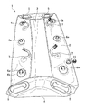
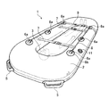
以下、図面を参照しながら、本願発明による避難用ボートの実施形態について説明する。図1は、避難用ボート1を、空気を抜いた状態で示す概観図である。図1において、避難ボート1の前端部(船首側)及び後端部(船尾側)は、内側に折り曲げた状態で示している。図2は、避難用ボート1全体に空気を注入した状態で示す概観図である。図2中、避難用ボート1に人間を乗せた状態を示すために、人間の姿を点線で示している。 Hereinafter, embodiments of an evacuation boat according to the present invention will be described with reference to the drawings. FIG. 1 is a schematic view showing the evacuation boat 1 in a state where air is removed. In FIG. 1, the front end portion (the bow side) and the rear end portion (the stern side) of the evacuation boat 1 are shown bent inward. FIG. 2 is a schematic view showing a state where air is injected into the entire evacuation boat 1. In FIG. 2, in order to show a state where a person is placed on the evacuation boat 1, the figure of the person is shown by a dotted line.
図1及び図2に示すように、避難用ボート1は、空気を注入したときに舷側を形成するアウターチューブ2と、避難用ボート1の底部を形成する底布4及び底布4の上部に固定されたフロアマット3とで、一体的に構成されている。避難用ボート1の船底の形状は、走行性や波切り性などが求められておらず、静止安定性に優れていることから、平底である。
As shown in FIGS. 1 and 2, the evacuation boat 1 includes an
避難用ボート1は、いわゆるゴムボートと呼ばれているボートの一種であるが、材質は、ゴム引布(布にゴムを貼りあわせたシートであり、布とゴムの特性を併せ持つ材料)が好ましい。また、このゴム引布においても、底布4は耐久性を考慮して例えばCSM(クロロスルホン化ポリエチレンゴム)を用いたゴム引布、アウターチューブ2は軽量化を考慮して例えばEP(エチレンプロピレン)ゴムを用いたゴム引布を用いることができる。また、アウターチューブ2には、避難用ボート1が海上に流出・浮遊している場合に目立つような色彩(例えば赤)の材質を用いるのがよい。
The evacuation boat 1 is a kind of boat called a so-called rubber boat, but the material is preferably a rubber-drawn cloth (a sheet in which rubber is bonded to a cloth, which has both characteristics of cloth and rubber). Also in this rubberized cloth, the
フロアマット3は、人間一人を横たえて乗せることができる略長方形のマットである。一人の人間を収容可能な領域であって、さらに人間を乗せて人手により移動させる場合の効率性を考慮すると、フロアマット3の長辺の長さは、1700mm〜2000mm程度、フロアマット3の横辺の長さは、500mm〜800mm程度、であることが好ましい。フロアマット3は、空気を注入可能な略長方形の袋体であって、空気を注入した場合に30mm〜40mm程度の厚みを有する平板となるマットでもよいし、ウレタン、スポンジ、ポリエチレンフォーム等の柔らかく弾力性があり、水に浮く素材で作製されたマットでもよい。いずれにせよ、フロアマット3のみでも人間一人を乗せた状態で沈まない程度の浮力を有するようにする。なお、空気注入型のフロアマット3の場合は、専用の空気注入口(図示せず)が設けられている
アウターチューブ2は、底布4の外縁部に一体的に形成された断面が円形状のチューブであり、空気を注入した状態でのチューブ径は、200mm〜250mmであることが好ましい。このチューブ径は、空気を注入した状態で人間をフロアマット3に乗せ、水に浮遊させた場合に、人間が容易にフロアマット3から水中に転げ落ちないように考慮されているものである。
The
アウターチューブ2の船首及び船尾に該当する部分の外周面には、それぞれ左右に取っ手5が設けられている。この取っ手5は、要支援者を避難用ボート1に乗せて移動させるときに、支援者がそれぞれ取っ手5を把持して避難用ボート1を担架として使用するためのものである。特に、アウターチューブ2に空気を注入していない段階で避難用ボート1を移動させる場合には、取っ手5が無ければ要支援者を迅速に移動させることが困難である。また、船首に設けられた取っ手5は、後述する台車を後部に取り付けて移動する場合に、避難用ボート1をけん引するためのロープ又はベルトを掛けるために用いる。
A
アウターチューブ2のそれぞれの長手方向の外周面には、長手方向に沿って、ロープ8を取付け支持するためのリング6aを固定したゴム基板6bが、複数設けられている。これらのリング6aに長手方向に沿ってロープ8を架け渡すことにより、避難用ボート1が浮遊している場合に、周囲の水中にいる人間がこのロープ8に捉まることが出来、避難用ボート1に乗せた要支援者のみならず、周囲の人間の救援にも役立つことが可能となる。また、船尾側のリング6aは、台車を避難用ボート1の底部に固定するためのベルトを係止するために用いる。
A plurality of
また、アウターチューブ2のそれぞれの長手方向の外周面には、要支援者をフロアマット3に乗せた状態で避難用ボート1が揺れた場合に要支援者が容易に転げ落ちないように、要支援者の身体を左右から締付けてフロアマット3に固定するためのシートベルト7が左右の対向した位置に取り付けられている。
Further, on the outer peripheral surfaces of the
なお、アウターチューブ2の外周面には、アウターチューブ2専用の空気注入口11が設けられている。
Note that an
避難用ボート1全体に空気を注入した後は、避難用ボート1の低面に台車を固定することができる。図2に示すように、台車(図示せず)に取り付けたバンド9を船尾側のリング6aに挿通させて固定し、船首側の取っ手5にロープ又はバンド(図示せず)を係止し、ロープ又はバンドをけん引することにより、支援者一人でも要支援者を乗せて避難用ボート1を移動させることが可能となる。
After the air is injected into the entire evacuation boat 1, the carriage can be fixed to the lower surface of the evacuation boat 1. As shown in FIG. 2, a
上記した避難用ボート1に取り付ける台車は、バンド9で固定できるものであればどのようなタイプものでも良い。例えば、4〜5輪のキャスターを備えた平台車である。
The carriage attached to the evacuation boat 1 may be of any type as long as it can be fixed with the
次に、避難用ボート1の使用方法について、津波が発生した場合を想定して説明する。この避難用ボート1を水害発生時に効果的に利用するためには、事前にある程度の避難計画の策定や避難訓練を実施していることが重要である。例えば、津波が発生した場合に、津波警報から津波の到達時刻と津波の高さを一刻も早く把握する手段を確保しておく、事前に避難場所までの所要時間(車椅子に乗せた要支援者を支援者が移動させる場合、要支援者を避難用ボート1に乗せて移動させる場合、支援者単独で移動させる場合等)を把握しておく、津波が発生した場合にその到達時刻と津波の高さから、どのように行動すべきかを時系列的に決めておく、等の準備は、避難用ボート1の津波発生時における有効な活用に必要である。 Next, a method of using the evacuation boat 1 will be described assuming a tsunami. In order to effectively use the evacuation boat 1 in the event of a flood, it is important that a certain evacuation plan and evacuation drill are carried out in advance. For example, in the event of a tsunami, the time required to reach the evacuation site in advance (assuming a supporter in wheelchairs) should be secured in advance to determine the tsunami arrival time and tsunami height from the tsunami warning. If the supporter moves, if the supporter needs to move on the evacuation boat 1 or if the supporter moves alone, etc.), if the tsunami occurs, the arrival time and the tsunami Preparation such as chronologically determining how to act from the height is necessary for effective use of the evacuation boat 1 when a tsunami occurs.
避難用ボート1は、ゴム引布で作製され、空気を注入しない状態では折りたたむことが出来るので、コンパクトに収納可能で、一人で持ち運びも可能である。従って、通常は、避難用ボート1は収縮した状態で保管されている。なお、避難用ボート1へ空気を注入するためには、電動ブロアを使用するのが効率的であり、特に施設では電動ブロアと発電機とを常備しておくことが必要である。 The evacuation boat 1 is made of rubberized cloth and can be folded in a state where air is not injected. Therefore, the evacuation boat 1 can be stored compactly and can be carried alone. Therefore, normally, the evacuation boat 1 is stored in a contracted state. In order to inject air into the evacuation boat 1, it is efficient to use an electric blower. In particular, it is necessary to keep an electric blower and a generator in a facility.
津波警報が発令されると、津波の到達時刻と津波の高さから判断して避難が必要とされる場合、支援者は車椅子では避難できない寝たきりの要支援者を避難用ボート1に乗せるために、まず、避難用ボート1のフロアマット3のみに空気を注入する。これは、要支援者を適当な位置に乗せるために効率的であるのと、要支援者をフロアマット3に載せる際の衝撃を小さくするためである。空気注入型でないウレタン等で作製されたフロアマット3の場合は、この動作は省略できる。
When the tsunami warning is issued, if the evacuation is required based on the arrival time of the tsunami and the height of the tsunami, the supporter is required to place a bedridden supporter who cannot evacuate with a wheelchair on the evacuation boat 1 First, air is injected only into the
要支援者を取りあえず戸外に運び出す場合や、二階以上に移動させる場合等には、フロアマット3のみに空気を注入した状態で、支援者がアウターチューブ2に取り付けられている取っ手5を把持して、避難用ボート1を担架のように使用して、要支援者を移動させることができる。
For example, when the supporter needs to be taken out of the house or moved to the second floor or higher, the supporter holds the
次に、電動ブロア等を用いて、アウターチューブ2に空気を注入する。この段階で、避難場所に移動できる余裕があれば、船尾側に設けたリング6aを利用して、台車を避難用ボート1に固定し、船首側に設けた取っ手5にロープ又はバンドを架け渡して、ロープ又はバンドで避難用ボート1をけん引することにより避難場所まで要支援者を支援者が一人で移動させることができる。
Next, air is injected into the
一方、津波が迫ってきて、避難用ボート1に乗せた要支援者全員を支援者が避難場所まで移動させる時間的な余裕がなく、支援者が避難可能な時間の限界が近づいた場合は、そのままであると支援者も一緒に遭難しかねないので、要支援者を避難用ボート1に乗せた状態で残し、支援者は避難せざるを得ない。しかしながら、津波に襲われても、避難用ボート1は完全に浮遊し、要支援者は水面下や水上のがれきから身体・頭部を保護することが出来、濡れないので冬季の災害でも低体温症の被害を防ぎやすい。このように避難用ボート1は津波に襲われても要支援者の当面の安全を確保し、救援を待つ状態にすることが出来る。 On the other hand, when the tsunami is approaching and there is no time for the supporter to move all the supporters on the evacuation boat 1 to the evacuation site and the time limit for the supporter to evacuate is approaching, If it is left as it is, the supporter may be distressed together, so the supporter is left in the evacuation boat 1 and the supporter has to evacuate. However, even after a tsunami, the evacuation boat 1 is completely floating, and supporters can protect their bodies and heads from underwater and debris on the water. It is easy to prevent damage. In this way, even if the evacuation boat 1 is attacked by a tsunami, it is possible to ensure the immediate safety of the supporter who needs it and to wait for rescue.
1 避難用ボート
2 アウターチューブ
3 フロアマット
4 底布
5 取っ手
6a リング
6b ゴム基板
7 シートベルト
8 ロープ
9 バンド
11 空気注入口
DESCRIPTION OF SYMBOLS 1
Claims (4)
Priority Applications (1)
| Application Number | Priority Date | Filing Date | Title |
|---|---|---|---|
| JP2016016944A JP6960208B2 (en) | 2016-02-01 | 2016-02-01 | Evacuation boat |
Applications Claiming Priority (1)
| Application Number | Priority Date | Filing Date | Title |
|---|---|---|---|
| JP2016016944A JP6960208B2 (en) | 2016-02-01 | 2016-02-01 | Evacuation boat |
Publications (2)
| Publication Number | Publication Date |
|---|---|
| JP2017136873A true JP2017136873A (en) | 2017-08-10 |
| JP6960208B2 JP6960208B2 (en) | 2021-11-05 |
Family
ID=59566578
Family Applications (1)
| Application Number | Title | Priority Date | Filing Date |
|---|---|---|---|
| JP2016016944A Active JP6960208B2 (en) | 2016-02-01 | 2016-02-01 | Evacuation boat |
Country Status (1)
| Country | Link |
|---|---|
| JP (1) | JP6960208B2 (en) |
Cited By (1)
| Publication number | Priority date | Publication date | Assignee | Title |
|---|---|---|---|---|
| CN111688864A (en) * | 2020-06-22 | 2020-09-22 | 广州市番高气模制品有限公司 | Inflatable stretcher boat |
Citations (8)
| Publication number | Priority date | Publication date | Assignee | Title |
|---|---|---|---|---|
| JPS494342U (en) * | 1972-04-12 | 1974-01-15 | ||
| JPS4918249U (en) * | 1972-05-22 | 1974-02-15 | ||
| JPS61191989U (en) * | 1985-05-23 | 1986-11-29 | ||
| JPH0740396U (en) * | 1993-12-27 | 1995-07-18 | ブリヂストンフローテック株式会社 | Stretcher |
| JPH08282586A (en) * | 1995-04-07 | 1996-10-29 | Toyo Tire & Rubber Co Ltd | Buoyant apparatus having expansion air chamber |
| JP2003002286A (en) * | 2001-06-20 | 2003-01-08 | Shimada & Co Ltd | Maneuvering system for rescue boat |
| US20120180218A1 (en) * | 2011-01-14 | 2012-07-19 | Honor Techniek B.V. | Stretcher usable as a life raft |
| JP2015013581A (en) * | 2013-07-05 | 2015-01-22 | 須藤 康夫 | Evacuation boat in flood disaster, and portable evacuation set in flood disaster |
-
2016
- 2016-02-01 JP JP2016016944A patent/JP6960208B2/en active Active
Patent Citations (8)
| Publication number | Priority date | Publication date | Assignee | Title |
|---|---|---|---|---|
| JPS494342U (en) * | 1972-04-12 | 1974-01-15 | ||
| JPS4918249U (en) * | 1972-05-22 | 1974-02-15 | ||
| JPS61191989U (en) * | 1985-05-23 | 1986-11-29 | ||
| JPH0740396U (en) * | 1993-12-27 | 1995-07-18 | ブリヂストンフローテック株式会社 | Stretcher |
| JPH08282586A (en) * | 1995-04-07 | 1996-10-29 | Toyo Tire & Rubber Co Ltd | Buoyant apparatus having expansion air chamber |
| JP2003002286A (en) * | 2001-06-20 | 2003-01-08 | Shimada & Co Ltd | Maneuvering system for rescue boat |
| US20120180218A1 (en) * | 2011-01-14 | 2012-07-19 | Honor Techniek B.V. | Stretcher usable as a life raft |
| JP2015013581A (en) * | 2013-07-05 | 2015-01-22 | 須藤 康夫 | Evacuation boat in flood disaster, and portable evacuation set in flood disaster |
Cited By (1)
| Publication number | Priority date | Publication date | Assignee | Title |
|---|---|---|---|---|
| CN111688864A (en) * | 2020-06-22 | 2020-09-22 | 广州市番高气模制品有限公司 | Inflatable stretcher boat |
Also Published As
| Publication number | Publication date |
|---|---|
| JP6960208B2 (en) | 2021-11-05 |
Similar Documents
| Publication | Publication Date | Title |
|---|---|---|
| PT1200693E (en) | AQUATIC RESCUE AND SAFETY DEVICE | |
| AU574172B2 (en) | Lifesaving craft | |
| US20110177733A1 (en) | Fire/water rescue sled for handicapped and elderly | |
| KR101954549B1 (en) | Stretcher | |
| CN204671757U (en) | A kind of multi-functional public building earthquake emergency slide escape | |
| JP6379326B2 (en) | Tsunami evacuation float | |
| US5354222A (en) | Water rescue sled | |
| US7744436B2 (en) | Rescue mat | |
| JP2017136873A (en) | Evacuation boat | |
| CN212828989U (en) | Inflatable life raft for offshore life saving | |
| US20050250396A1 (en) | Rescue lift | |
| JP6894633B2 (en) | Life jacket and hood | |
| JP6026693B1 (en) | Life preserver | |
| JP2009101101A (en) | Stretcher for both of flat land and slope land | |
| JPH04189355A (en) | Gas filling type lifesaving stretcher | |
| JP2015013581A (en) | Evacuation boat in flood disaster, and portable evacuation set in flood disaster | |
| US11731745B1 (en) | Personal flotation, evacuation and rescue device | |
| JP6781874B1 (en) | Wheelchair with tsunami disaster prevention function | |
| JP2000176037A (en) | Emergency implement storage case | |
| AU2011250700B2 (en) | Person transporter for emergency use | |
| WO2004026210A1 (en) | Person transporter for emergency use | |
| JPH04187147A (en) | Litter in water | |
| FR2742723A1 (en) | RESCUE AND RESCUE DEVICE FOR PEOPLE IN OR ON THE WATER | |
| JP3192617U (en) | Disaster evacuation chair | |
| JP2010193927A (en) | Protector for escape |
Legal Events
| Date | Code | Title | Description |
|---|---|---|---|
| A621 | Written request for application examination |
Free format text: JAPANESE INTERMEDIATE CODE: A621 Effective date: 20190130 |
|
| A711 | Notification of change in applicant |
Free format text: JAPANESE INTERMEDIATE CODE: A711 Effective date: 20190130 |
|
| A521 | Request for written amendment filed |
Free format text: JAPANESE INTERMEDIATE CODE: A821 Effective date: 20190130 |
|
| A977 | Report on retrieval |
Free format text: JAPANESE INTERMEDIATE CODE: A971007 Effective date: 20191125 |
|
| A131 | Notification of reasons for refusal |
Free format text: JAPANESE INTERMEDIATE CODE: A131 Effective date: 20191218 |
|
| A521 | Request for written amendment filed |
Free format text: JAPANESE INTERMEDIATE CODE: A523 Effective date: 20200217 |
|
| A131 | Notification of reasons for refusal |
Free format text: JAPANESE INTERMEDIATE CODE: A131 Effective date: 20200804 |
|
| A521 | Request for written amendment filed |
Free format text: JAPANESE INTERMEDIATE CODE: A821 Effective date: 20200930 |
|
| A02 | Decision of refusal |
Free format text: JAPANESE INTERMEDIATE CODE: A02 Effective date: 20210309 |
|
| A521 | Request for written amendment filed |
Free format text: JAPANESE INTERMEDIATE CODE: A523 Effective date: 20210609 |
|
| C60 | Trial request (containing other claim documents, opposition documents) |
Free format text: JAPANESE INTERMEDIATE CODE: C60 Effective date: 20210609 |
|
| C11 | Written invitation by the commissioner to file amendments |
Free format text: JAPANESE INTERMEDIATE CODE: C11 Effective date: 20210713 |
|
| A911 | Transfer to examiner for re-examination before appeal (zenchi) |
Free format text: JAPANESE INTERMEDIATE CODE: A911 Effective date: 20210816 |
|
| C21 | Notice of transfer of a case for reconsideration by examiners before appeal proceedings |
Free format text: JAPANESE INTERMEDIATE CODE: C21 Effective date: 20210903 |
|
| TRDD | Decision of grant or rejection written | ||
| A01 | Written decision to grant a patent or to grant a registration (utility model) |
Free format text: JAPANESE INTERMEDIATE CODE: A01 Effective date: 20211005 |
|
| A61 | First payment of annual fees (during grant procedure) |
Free format text: JAPANESE INTERMEDIATE CODE: A61 Effective date: 20211011 |
|
| R150 | Certificate of patent or registration of utility model |
Ref document number: 6960208 Country of ref document: JP Free format text: JAPANESE INTERMEDIATE CODE: R150 |