JP2017134291A - Developer conveyance device and image forming apparatus - Google Patents
Developer conveyance device and image forming apparatus Download PDFInfo
- Publication number
- JP2017134291A JP2017134291A JP2016014830A JP2016014830A JP2017134291A JP 2017134291 A JP2017134291 A JP 2017134291A JP 2016014830 A JP2016014830 A JP 2016014830A JP 2016014830 A JP2016014830 A JP 2016014830A JP 2017134291 A JP2017134291 A JP 2017134291A
- Authority
- JP
- Japan
- Prior art keywords
- developer
- toner
- transport
- detection surface
- conveying
- Prior art date
- Legal status (The legal status is an assumption and is not a legal conclusion. Google has not performed a legal analysis and makes no representation as to the accuracy of the status listed.)
- Pending
Links
Images


Abstract
Description
本発明は、ファクシミリ、複写機、プリンタ等の画像形成装置に用いられる現像剤搬送装置に関する。 The present invention relates to a developer conveying device used in an image forming apparatus such as a facsimile, a copying machine, and a printer.
従来、像担持体に形成された静電潜像(静電像)を、現像剤を用いてトナー像に現像する現像装置が搭載された画像形成装置が知られている。 2. Description of the Related Art Conventionally, there is known an image forming apparatus equipped with a developing device that develops an electrostatic latent image (electrostatic image) formed on an image carrier into a toner image using a developer.
このような、現像剤を用いる画像形成装置では、搬送スクリュー等で現像剤を搬送する場合、現像剤がトナーボトル等の現像剤収容容器から現像装置内の現像容器に所定の時間内に所定量の現像剤が搬送されないと、エラーとして装置本体を停止させる構成を備えたものがある。この構成において、所定の時間内に所定量の現像剤(トナー)が搬送されたかどうかは、現像剤搬送路内に配置されてトナーの有無を検知するトナーセンサの検知時間等に基づいて判断される(特許文献1参照)。 In such an image forming apparatus using a developer, when the developer is transported by a transport screw or the like, the developer is transferred from the developer container such as a toner bottle to the developer container in the developing device within a predetermined amount within a predetermined time. If the developer is not transported, there is an apparatus that is configured to stop the apparatus main body as an error. In this configuration, whether or not a predetermined amount of developer (toner) has been transported within a predetermined time is determined based on a detection time of a toner sensor that is disposed in the developer transport path and detects the presence or absence of toner. (See Patent Document 1).
しかしながら、特許文献1記載の現像剤補給システムのように、現像剤収容容器から現像容器に補給するタイミングを、現像剤収容容器から現像容器に連通する現像剤搬送路内に配置されたトナーセンサで行おうとすると、次のような問題を生じるおそれがある。つまり、現像剤収容容器からの現像剤が全て現像容器に搬送されたにも拘わらず、トナーセンサの検知面の周囲にだけ残ったトナーをトナーセンサが検知することがある。その場合は、現像剤搬送路内にトナーがほとんど存在しないにも拘わらず、現像剤収容容器(現像剤収容手段)から現像剤の補給が行われない事象が引き起こされてしまう。
However, as in the developer replenishment system described in
上記事象を回避するため、トナーセンサの検知面近傍にトナーが滞留しないように検知面を掻き取るように、搬送スクリューから検知面に対して略直交する方向に平板状の掻き取り部材を設け、回転する搬送スクリューに同期して移動することで検知面近傍のトナーを掻き取るようにする技術が知られている。しかしながら、この平板状の掻き取り部材は、搬送スクリューの軸部からトナーセンサに向かって垂直に矩形形状に設けられる。このため、トナーを掻き取っても上方に掻き上げるだけでトナーセンサの検知面近傍に再び落下してしまい、トナーを搬送する速度も低下してしまう。 In order to avoid the above phenomenon, a flat scraping member is provided in a direction substantially perpendicular to the detection surface from the conveying screw so as to scrape the detection surface so that toner does not stay in the vicinity of the detection surface of the toner sensor. A technique is known in which toner in the vicinity of a detection surface is scraped off by moving in synchronization with a rotating conveying screw. However, the flat scraping member is provided in a rectangular shape vertically from the shaft portion of the conveying screw toward the toner sensor. For this reason, even if the toner is scraped off, it is dropped again in the vicinity of the detection surface of the toner sensor only by scraping upward, and the speed at which the toner is conveyed is also reduced.
本発明は、現像剤の搬送を適正に実施可能な現像剤搬送装置を提供することを目的とする。 SUMMARY OF THE INVENTION An object of the present invention is to provide a developer transport device that can appropriately transport a developer.
本発明は、現像剤搬送装置において、現像剤を収容する現像剤収容手段と、前記現像剤収容手段から供給された現像剤を現像剤搬送方向の下流側に搬送する搬送部材を有する現像剤搬送部と、前記現像剤搬送部内の現像剤を検知可能な検知面を該現像剤搬送部内に向けた現像剤検知手段と、前記搬送部材においての前記検知面と対向可能な位置に設けられ、該搬送部材の回転により前記検知面近傍の現像剤を清掃する清掃部材と、を備え、前記清掃部材は、前記搬送部材の回転に伴って前記検知面に弾性的に摺接可能で、前記現像剤搬送方向に直交する方向の長さが該現像剤搬送方向の上流側から下流側に向かって漸次長くなるように先端縁部が傾斜することを特徴する。 The present invention relates to a developer conveying device having developer accommodating means for accommodating a developer, and a conveying member for conveying the developer supplied from the developer accommodating means to the downstream side in the developer conveying direction, in the developer conveying device. A developer detecting means having a detection surface capable of detecting the developer in the developer conveying portion directed toward the developer conveying portion, and a position facing the detection surface in the conveying member, A cleaning member that cleans the developer in the vicinity of the detection surface by the rotation of the conveying member, and the cleaning member can be elastically slidably contacted with the detection surface as the conveying member rotates, and the developer The tip edge portion is inclined so that the length in the direction orthogonal to the transport direction gradually increases from the upstream side to the downstream side in the developer transport direction.
本発明は、現像剤搬送装置において、現像剤を収容する現像剤収容手段と、前記現像剤収容手段から供給された現像剤を現像剤搬送方向の下流側に搬送する搬送部材を有する現像剤搬送部と、前記現像剤搬送部内の現像剤を検知可能な検知面を該現像剤搬送部内に向けた現像剤検知手段と、前記搬送部材においての前記検知面と対向可能な位置に設けられ、該搬送部材の回転により前記検知面近傍の現像剤を清掃する清掃部材と、を備え、前記搬送部材は、回転軸を中心に回転して回転軸方向に現像剤を搬送する搬送スクリューであって、前記清掃部材に近い領域のスクリューピッチは他の領域のスクリューピッチより狭いことを特徴する。 The present invention relates to a developer conveying device having developer accommodating means for accommodating a developer, and a conveying member for conveying the developer supplied from the developer accommodating means to the downstream side in the developer conveying direction, in the developer conveying device. A developer detecting means having a detection surface capable of detecting the developer in the developer conveying portion directed toward the developer conveying portion, and a position facing the detection surface in the conveying member, A cleaning member that cleans the developer in the vicinity of the detection surface by rotation of the transport member, and the transport member is a transport screw that rotates around the rotation shaft and transports the developer in the rotation axis direction. The screw pitch in the region close to the cleaning member is narrower than the screw pitch in other regions.
本発明は、現像剤搬送装置において、現像剤を収容する現像剤収容手段と、前記現像剤収容手段から供給された現像剤を現像剤搬送方向の下流側に搬送する第1の搬送部材を有する現像剤搬送部と、前記現像剤搬送部内の現像剤を検知可能な検知面を該現像剤搬送部内に向けた現像剤検知手段と、前記搬送部材においての前記検知面と対向可能な位置に設けられ、該搬送部材の回転により前記検知面近傍の現像剤を清掃する清掃部材と、を備え、前記清掃部材が清掃した現像剤を前記下流側に搬送する第2の搬送部材を有することを特徴する。 The present invention includes, in the developer conveying apparatus, a developer accommodating unit that accommodates the developer, and a first conveying member that conveys the developer supplied from the developer accommodating unit to the downstream side in the developer conveying direction. Provided at a position where the developer conveying section, a detection surface capable of detecting the developer in the developer conveying section facing the inside of the developer conveying section, and a position facing the detection surface of the conveying member And a cleaning member that cleans the developer in the vicinity of the detection surface by rotation of the transport member, and has a second transport member that transports the developer cleaned by the cleaning member to the downstream side. To do.
本発明によれば、現像剤の搬送を適正に実施することが可能になる。 According to the present invention, it is possible to appropriately carry the developer.
以下、本発明の実施形態に係る画像形成装置1について図面を参照しながら説明する。まず、本実施形態に係る画像形成装置1の全体構造について図1を参照しながら説明する。図1は、本実施形態に係る画像形成装置1の全体構造を模式的に示す断面図である。以下においては、ユーザが画像形成装置1に対して各種入力及び設定を行う不図示の操作パネルに臨む手前側を画像形成装置1の「正面側」といい、奥側を「背面側」という。つまり、図1は、正面側から見た画像形成装置1の内部構成を示した断面図である。なお、図1では、後述するトナー補給機構(現像剤搬送装置)15を図示省略している。
Hereinafter, an
図1に示すように、画像形成装置1は装置本体1aを有し、装置本体1a内の下部に、シートSを給送するシート給送装置2を備えている。また、装置本体1a内には、制御手段としての制御部7が設けられている。装置本体1a内におけるシート給送装置2の上方には、給送されたシートSに画像を形成する画像形成部3と、シートSに画像を定着させる定着装置4と、画像が定着されたシートSを排出するシート排出部5とが順次配置されている。装置本体1aの上部には、原稿の画像を読み取り可能な画像読取部6が配置されている。なお、画像形成部3及び定着装置4により、画像形成手段が構成されている。
As shown in FIG. 1, the
シート給送装置2は、シートSを積載する積載トレイ21と、積載トレイ21に積載されたシートSを繰り出すピックアップローラ22と、ピックアップローラ22で繰り出されたシートSを分離給送する分離給送部23とを備えている。また、シート給送装置2は、画像形成装置1の側面側からシートSを手差し給送可能な手差し給送部24を備えている。この手差し給送部24は、シートSを積載する開閉式の手差しトレイ25と、手差しトレイ25に積載されたシートSを分離給送する分離給送部26とを備えている。
The
画像形成部3は、トナー像が形成される像担持体としての感光ドラム31と、感光ドラム31の表面を一様に帯電する帯電ローラ32と、レーザ光を照射して感光ドラム31に静電潜像を形成するレーザ照射装置39とを備えている。さらに、画像形成部3は、感光ドラム31上の静電潜像をトナー像として可視化する現像装置34と、感光ドラム31に当接して転写ニップ部Nを形成する転写ローラ35とを備えている。現像装置34は、感光ドラム31の表面にトナーを供給する現像スリーブ14を備えている。現像装置34は、感光ドラム31に形成された静電潜像をトナー(現像剤)tで現像する現像手段を構成している。本実施形態に係る画像形成装置1は、後述するトナー補給機構(現像剤搬送装置)15により現像装置34にトナーtを搬送し補給するように構成されている。
The
定着装置4は、画像形成部3のシート搬送方向下流側(以下、単に「下流側」ともいう)のシート搬送路に配置されており、定着ユニット40及び冷却ファン41を備えている。
The fixing device 4 is arranged in a sheet conveyance path downstream of the
シート排出部5は、定着装置4の下流側に配置されており、シートSを装置本体1aの内部から排出する排出ローラ対51と、排出されたシートSを積載する排出トレイ52とを備えている。
The
画像読取部6は、原稿(不図示)を載置する原稿載置部61と、原稿載置部61に載置された原稿の画像情報を読み取る読取スキャナ62とを備えている。なお、図1において、図7等に示すトナーボトルユニット27やトナー搬送路28、並びにその周辺部については図示を省略している。
The
次に、上述の構成を備えた画像形成装置1の制御部(制御手段)7による画像形成ジョブを実行する画像形成動作について説明する。
Next, an image forming operation for executing an image forming job by the control unit (control unit) 7 of the
すなわち、画像形成ジョブが開始されると、不図示のパーソナルコンピュータ(PC)もしくは読取スキャナ62から送信された原稿等の画像情報(画像情報信号)に応じて、レーザ照射装置39が感光ドラム31の表面にレーザ光を照射する。これにより、帯電ローラ32によって所定の極性電位に予め一様に帯電されている感光ドラム31の表面が露光され、感光ドラム31の表面に静電潜像が形成される。そして、感光ドラム31に形成された静電潜像は、現像装置34により現像されてトナー像として可視化される。
In other words, when the image forming job is started, the
上述したトナー像の形成動作に並行して、シート給送装置2から1枚ずつ分離給送されたシートSは、搬送ローラ対10によりその下流側のシート搬送路に配置されたレジストローラ対11に搬送され、停止中のレジストローラ対11のニップにシートS先端が突き当たることで斜行が矯正される。その後、斜行が矯正されたシートSは、所定のタイミングで転写ニップ部Nに搬送され、可視化された感光ドラム31上のトナー像が転写ローラ35によって転写される。
In parallel with the toner image forming operation described above, the sheet S separated and fed one by one from the
トナー像が転写されたシートSは、転写ニップ部Nから定着装置4に搬送され、定着ユニット40で加熱及び加圧されることによってトナーが溶融され、画像としてシートS上に定着される。その後、画像が定着されたシートSは、排出ローラ対51によって排出トレイ52に排出され、画像形成ジョブが終了する。
The sheet S to which the toner image has been transferred is conveyed from the transfer nip portion N to the fixing device 4 and is heated and pressed by the fixing
[トナー補給機構]
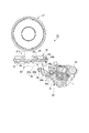
次に、画像形成装置1に設けられている現像剤搬送装置としてのトナー補給機構15について、図7を参照して説明する。図7は、本実施形態のトナー補給機構15の概略構成を示す正面図である。
[Toner supply mechanism]
Next, a
すなわち、図7に示すように、トナー補給機構15は、トナーボトルユニット27を有しており、このトナーボトルユニット27には、トナー(現像剤)tを収容する現像剤収容手段としてのトナーボトル27bが回転可能に装着されている。トナーボトルモータ13の駆動でトナーボトル27bが回転すると、トナーボトルユニット27に設けられたトナー補給口27aからトナー搬送路28にトナーtが放出される。
That is, as shown in FIG. 7, the
トナー搬送路28は、上部面に、トナー補給口27aに連通するトナー受け口16cを有し、搬送面(下部面)16aにおける一端部に、現像装置34のトナー受け部34bにトナーtを放出するトナー放出口16bを有している。トナー搬送路28における図7の左右方向の両端部に、搬送スクリュー29の軸部29bの両端部をそれぞれ回転自在に嵌合させる軸支持孔16d,16eを有している。搬送スクリュー(搬送部材)29は、軸部29bを中心として一方向に螺旋状に巻き付くように形成されたスパイラル部29aを有している。搬送スクリュー(搬送部材)29は、軸部(回転軸)29bを中心に回転して回転軸方向にトナー(現像剤)tを搬送する。
The
トナー搬送路28にトナーtが補給されると、搬送スクリューモータ12の駆動で回転する搬送スクリュー29のスパイラル部29aにより、矢印30a,30bで示す経路を含むトナー搬送経路30に沿って搬送されて、下方の現像装置34のトナー受け部34bに補給される。トナー搬送方向は、図7においては矢印30aで示す方向であり、図2及び図4においては矢印42bで示す方向である。
When the toner t is supplied to the
トナーボトル27bは、トナーボトルユニット27に着脱自在に設けられており、ユーザ等によって交換可能である。
The
また、トナー搬送路28内には、トナー検知手段としての搬送路トナー検知センサ33が配置されている。搬送スクリュー29の搬送路トナー検知センサ33に対向する位置に平板状の掻き取り部材46が設けられている。搬送路トナー検知センサ33は、搬送スクリュー29の回転でトナーtが搬送されるホッパ容器16の搬送面16aからホッパ容器16内に、トナーtを検知可能な検知面33aを露出させている。搬送路トナー検知センサ33は、検知面33aでトナーtを検知した際の検知信号を制御部7(図7参照)に出力する。なお、搬送路トナー検知センサ33は、現像剤検知手段を構成する。
Further, in the
また、現像装置34内には、感光ドラム31に供給するためのトナーtを収納する現像容器34aが設けられている。さらに、現像装置34の現像容器34aの内壁部には、現像装置トナー検知センサ36が配置されており、このセンサ36により、トナーtが現像容器34a内の所定の高さにあるか否かが検知され、その検知信号が制御部7(図1参照)に出力される。なお、本実施形態における搬送路トナー検知センサ33及び現像装置トナー検知センサ36として、例えば透磁率検知センサやピエゾセンサ等を用いることが可能である。
In addition, a developing
ここで、図8及び図9を参照して、搬送路トナー検知センサ33の検知面33aにトナーtが滞留しないようにする、本実施形態の掻き取り部材46について説明する。なお、図8は、搬送路トナー検知センサ33及び掻き取り部材46を拡大して示す断面図、図9は、図6のフローチャートに沿ってトナー供給が制御された場合のホッパ容器16及び現像装置34を示す断面図である。
Here, the scraping
図8及び図9に示すように、トナー搬送路28に配置された搬送路トナー検知センサ33の検知面33aに対向するように、搬送スクリュー29には、掻き取り部材46が設けられている。掻き取り部材46は、搬送路トナー検知センサ33の検知面33aを搬送スクリュー29の回転時に掻き取ることが可能となるように、検知面33aに対し略直交する方向に平板状に起立して、トナーが検知面33aに滞留しないように除去するように構成される。搬送スクリュー29はABS等の樹脂材から構成されており、平板状の掻き取り部材46は、ウレタン等の可撓性を有する樹脂材料から構成されており、搬送スクリュー29の軸部29bの検知面33aに対向する部位に両面テープ等で接着され、軸部29bから突出するように構成されたものである。搬送スクリュー(搬送部材)29は、軸部(回転軸)29bの長手方向に可撓性を有するシートを固定し、軸部29bを中心に回転して軸部29bの周方向に現像剤を搬送する。
As shown in FIGS. 8 and 9, a scraping
次に、図5を参照して、本実施形態に係るトナー補給に係る制御系について説明する。なお、図5は、本実施形態に係るトナー補給に係る制御系を示す制御ブロック図である。 Next, a control system related to toner supply according to the present embodiment will be described with reference to FIG. FIG. 5 is a control block diagram showing a control system related to toner supply according to the present embodiment.
図5に示すように、CPU,RAM,ROMを有する制御部7には、入力に現像装置トナー検知センサ36と搬送路トナー検知センサ33とが接続されており、出力に搬送スクリューモータ12とトナーボトルモータ13とが接続されている。制御部7は、現像装置トナー検知センサ36と搬送路トナー検知センサ33からの検知信号に基づき、搬送スクリューモータ12とトナーボトルモータ13に駆動信号を出力する。
As shown in FIG. 5, a developing device
[トナーボトルにトナーがある場合のトナー補給動作]
次に、トナーボトルにトナーがある場合のトナー補給動作について、図6及び図9を参照して説明する。なお、図6は、トナー補給動作の流れを示したフローチャートである。
[Toner supply operation when toner is in toner bottle]
Next, a toner replenishing operation when toner is present in the toner bottle will be described with reference to FIGS. FIG. 6 is a flowchart showing the flow of the toner supply operation.
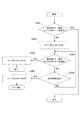
すなわち、トナー補給動作は、シートSに画像を形成する動作と並行して行われる。トナー補給動作を行なう場合、制御部7(図1、図5)はまず、現像装置トナー検知センサ36がトナーtを検知しているか否かを判断する。制御部7は、トナーtを検知していないと判断した場合には、搬送スクリューモータ12(図7)を駆動させる。これにより、ホッパ容器16のトナー搬送路28内にて搬送スクリュー29が回転してトナーtを搬送し、トナー放出口16bからトナー受け部34bに供給する。一方、制御部7は、現像装置トナー検知センサ36がトナーtを検知したと判断した時点で、搬送スクリューモータ12の駆動を停止して、現像装置34へのトナー補給を停止させる。
That is, the toner replenishing operation is performed in parallel with the operation of forming an image on the sheet S. When the toner replenishing operation is performed, the control unit 7 (FIGS. 1 and 5) first determines whether or not the developing device
また、制御部7は、搬送路トナー検知センサ33がトナーtを検知しているか否かを判断する(S301)。制御部7は、搬送路トナー検知センサ33がトナーtを検知したと判断した場合には(S301:YES)、処理を終了する。
Further, the
一方、ステップS301で、搬送路トナー検知センサ33がトナーtを検知しないと判断した場合(S301:NO)、制御部7は、搬送路トナー検知センサ33がトナーtを検知するまでトナーボトルモータ13をON(駆動)する(S302)。これにより、トナーボトル27bからトナー搬送路28にトナーtが供給される。そして制御部7は、搬送路トナー検知センサ33がトナーtを検知した時点(ステップS303:YES)で、トナーボトルモータ13をOFF(停止)してトナー補給を停止させ(S305)、処理を終了する。
On the other hand, when it is determined in step S301 that the conveyance path
また、制御部7は、搬送路トナー検知センサ33がトナーtを検知しないと判断した場合には(ステップS303:NO)、所定時間経過したか否かを判断し(S304)、経過しない場合には(S304:NO)ステップS303の処理に戻る。一方、所定時間経過したと判断した場合(S304:YES)、制御部7は、トナーボトルモータ13をOFF(停止)してトナー補給を停止させ(S306)、トナー無しとする。
If the conveyance path
上述のように制御部7は、現像装置トナー検知センサ36がトナーを検知しなくなると、搬送スクリューモータ12を駆動して搬送スクリュー29を回転させ、トナー搬送路28から現像装置34にトナーtを供給する。また、搬送路トナー検知センサ33がトナーtを検知しなくなると、トナーボトルモータ13を駆動してトナーボトル27bを回転させ、トナーボトル27bからトナー搬送路28にトナーtを供給する。以上の動作を繰り返すことにより、トナーボトル27bからトナー搬送路28へ、トナー搬送路28から現像装置34へと、トナーtを円滑に供給することができる。
As described above, when the developing device
[トナーボトル内のトナーが無くなった場合のトナー補給動作]
次に、トナーボトル27b内のトナーtが無くなった場合のトナー補給動作について、図10(a)〜(c)を参照して説明する。なお、図10(a)〜(c)は、トナーボトル内のトナーが無くなってから新しいトナーボトル27bに交換した際の様子を示す図である。図10(a)は、トナー搬送路28内のトナーtが少なくなっていく様子を示す図である。図10(b)は、トナー搬送路28内のトナーtが無くなった際の様子を示す図である。図10(c)は、新たなトナーボトル27bに交換されて搬送路トナー検知センサ33がトナーtを検知するまでトナーボトル27bからトナー搬送路28にトナーtが供給された際の様子を示す図である。
[Toner supply operation when toner in the toner bottle runs out]
Next, a toner replenishing operation when the toner t in the
すなわち、トナーボトル27bからトナー搬送路28及び現像装置34にトナーtが供給されて画像形成が行われると、やがて現像装置トナー検知センサ36がトナーtを検知できる状態で、かつ、搬送路トナー検知センサ33がトナーを検知できない状態となる。
That is, when the toner t is supplied from the
図10(a)に示すように、トナーボトル27b内のトナーtが無くなり、搬送路トナー検知センサ33がトナーtを検知できない状態になった場合であっても、画像形成処理は実行され、現像装置34内のトナーtが消費される。そして、トナーtの消費に伴い、現像装置トナー検知センサ36がトナーtを検知できない状態となる。
As shown in FIG. 10A, even when the toner t in the
この場合、上述の通り搬送スクリューモータ12を駆動させ、搬送スクリュー29の回転によりトナー搬送路28のトナー放出口16bから、現像装置34のトナー受け部34bにトナーtを供給する。このとき既に、トナーボトル27bからトナー搬送路28へのトナー供給はできない状態にあることから、搬送スクリューモータ12を駆動させる度に、トナー搬送路28内のトナーtは、トナー放出口16bから現像装置34のトナー受け部34bに放出されることで減少する。
In this case, the conveying
この状態で、引き続き画像形成処理が行なわれると、搬送スクリューモータ12によるトナー供給が実行され続け、やがてはトナー搬送路28内にトナーtが無い状態、即ち搬送スクリューモータ12がトナーtを供給していない空回り状態になる。
In this state, when the image forming process is continued, the toner supply by the conveying
そして、図10(b)に示すように、現像装置トナー検知センサ36がトナー検知をしない状態で、一定時間経過しても現像装置トナー検知センサ36がトナー検知をしない状態になると、制御部7は、トナーボトル27b内にトナーは無いと判断する。そして、表示手段である操作部(不図示)に、トナーボトル27bの交換を促す内容を表示し、かつ、画像形成ジョブを受け付けない状態、即ち画像形成装置1が画像形成を行わない状態にする。この間が、搬送スクリューモータ12がトナーtを供給していない空回り状態の期間である。
Then, as shown in FIG. 10B, when the developing device
さらに、図10(c)に示すように、トナーtが無くなったトナーボトル27bを、トナーtが充填されている新しいトナーボトル27bに交換されると、トナー搬送路28内及び現像装置34内に、順次トナーtが補給される。そして、搬送路トナー検知センサ33及び現像装置トナー検知センサ36がトナーtを検知した状態、即ちトナー補給動作が完了した状態になる。
Further, as shown in FIG. 10C, when the
以上の動作シーケンスにおいて、トナー補給シーケンスが実行される。 In the above operation sequence, the toner replenishment sequence is executed.
ここで、図11に、搬送路トナー検知センサ33によるトナーtの検出波形を示す。図11に示すように、アナログ波形を出力値としているため、搬送路トナー検知センサ33の周辺にトナーtがある場合、搬送路トナー検知センサ33周辺のトナーtが多い際に出力値は大きくなり、少ない際に出力値は小さくなる。図11は、平板状の掻き取り部材46のみを検知面33aに対向させて検知面33aを清掃する場合にトナーボトル27bから1[g]のトナーtを補給した際の検知波形を示すグラフ図である。図11及び後述の図12、図13のグラフでは、縦軸に搬送路トナー検知センサ33の出力(V)をとり、横軸に時間(t)をとっている。図11〜図13における符号Pは、トナーボトル27bから1[g]補給したときの波形を表している。
Here, FIG. 11 shows a detection waveform of the toner t by the conveyance path
トナーボトル27bから現像容器34aに補給するタイミングを、トナーボトル27bから現像容器34aを連通するトナー搬送路28内に露出する搬送路トナー検知センサ33で行おうとすると、以下のような問題を生じるおそれがある。即ち、トナーボトル27bから現像容器34aにトナーtを送ったにも拘わらず、検知面33aの周囲に残存したトナーtを搬送路トナー検知センサ33が検知してしまい、トナー搬送路28内にトナーボトル27bから補給が行われない事象が起こってしまう。
If the timing for replenishing the developing
図11は、平板状の掻き取り部材46のみを使用する場合の波形であり、トナーtがトナー搬送路28に入ってきて搬送路トナー検知センサ33がトナーtを検知すると図11のように立ち上がる。実際は、アナログ出力であればもう少し徐々に立ち上がるが、図11及び後述の図12、図13においては理解が容易になるように記載した。
FIG. 11 shows a waveform when only the
図11において、三角波状になっている信号Wは、搬送スクリュー29の回転に合わせて平板状の掻き取り部材46が検知面33a付近のトナーtを掻き取るため、搬送路トナー検知センサ33の出力が上下している。しかし、この掻き取り部材46による掻き取り量は少なく、デジタル波形で言うとOFFの領域にまで至らないため、デジタル波形で見るとON状態が続き、パルスPで示されるトナー補給が行われていないことになる。
In FIG. 11, the signal W in the form of a triangular wave is output from the conveyance path
図11に対応する構成例の場合には、搬送スクリュー29の軸部29bから検知面33aに対し略垂直に壁を立てるように平板状の掻き取り部材46を形成し、この掻き取り部材46を搬送スクリュー29と共に回転させて、検知面33a周囲にトナーtが滞留しないようにする。しかしながら、搬送スクリュー29から伸ばした平板状の掻き取り部材46によると、その先端部と検知面33aとの間の寸法公差を厳密に規制したり、検知面33aの検知範囲を規制したりすることは極めて困難である。
In the case of the configuration example corresponding to FIG. 11, a plate-
また、図11に対応する構成例の場合には、掻き取り部材46が検知面33aに接触する面が該面33aに対して水平に形成されているため、トナーをトナー搬送方向に搬送する力がなく、従って、持上げて落とすという動作を繰り返す。そのため、図11の構成例の搬送路トナー検知センサ33は、掻き取った同じトナーを何度も検知してしまうという問題がある。そのため、適正なOFF状態になるまでに時間を要してしまう。
In the case of the configuration example corresponding to FIG. 11, since the surface where the scraping
これに対し、図12では、平板状の掻き取り部材46に加えて、先端部が平行な矩形状のシール状弾性部材を設けた構成例を示している。図12は、トナーボトル27bからトナーtを補給されたときの補給動作と搬送路トナー検知センサ33の出力との関係を表している。
On the other hand, FIG. 12 shows a configuration example in which, in addition to the flat plate-
図12に対応する構成例の場合には、図13に対応する本実施形態の構成によるものとは異なり、シール状弾性部材が検知面33aに接する先端部が水平状態での波形である。図12では、図11の構成例と比較すると、搬送路トナー検知センサ33のON/OFFは確実に検知できるが、ON/OFFを判断するのにやや時間を要している。また、図12より、トナーボトル27bからトナー搬送路28へトナーtの補給動作が行われると、少しの時間を置いて搬送路トナー検知センサ33がトナーtを検知し、現像容器34aへとトナーtを搬送していることが分かる。この構成例では、1[g]という少ない量でありながら約20秒間検知し続け、次の補給動作を行っている。
In the case of the configuration example corresponding to FIG. 12, unlike the configuration of the present embodiment corresponding to FIG. 13, the tip portion where the sealing elastic member is in contact with the
図11及び図12の双方の問題と共に解決した図13に示す本実施形態では、トナー搬送方向に対してシール状弾性部材44の先端縁部44aの長さを変えている。これにより、検知面33aの周囲に残存している残トナーを適正に掻き取ると共に、搬送スクリュー29によるトナーの搬送力を低下させないように構成している。
In the present embodiment shown in FIG. 13 which is solved together with the problems of both FIG. 11 and FIG. 12, the length of the
すなわち、図13は、トナーボトル27bからトナー搬送路28に一定量ずつトナーtを補給したときの搬送路トナー検知センサ33の本実施形態による出力値を示し、図11と比較しても同じ量のトナーtの補給に要する検知時間は短い。これにより、搬送路トナー検知センサ33に滞留することなく、トナーtを搬送していることがわかる。
That is, FIG. 13 shows the output value according to this embodiment of the conveyance path
以下、このような本実施形態について、図2〜図4を参照して詳細に説明する。なお、図2は、本実施形態に係るトナー補給機構の概略構成を示す断面図である。図3(a)〜(c)は、本実施形態に係る清掃部材38及び搬送路トナー検知センサ33等をそれぞれ異なる状態で拡大して示す図である。図3(a)は、清掃部材38が検知面33aに接触した状態を示す正面断面図、図3(b)は、図3(a)を同図左方から見た状態で示す側面図である。図3(c)は、図3(a)の位置より搬送スクリュー29が更に回転した状態での清掃部材38の接触状態を示す正面断面図である。図4(a)は、本実施形態に係る搬送スクリュー29を拡大して示す図、図4(b),(c),(d),(e)は、搬送スクリュー29の回転に伴って順次変化する清掃部材38の状態を段階的に示す図である。
Hereinafter, this embodiment will be described in detail with reference to FIGS. FIG. 2 is a cross-sectional view showing a schematic configuration of the toner supply mechanism according to the present embodiment. FIGS. 3A to 3C are diagrams illustrating the cleaning
すなわち、本実施形態では、図2に示すように、搬送スクリュー29においての検知面33aと対向可能な位置に設けられ、該搬送スクリュー29の回転により検知面近傍のトナー(現像剤)tを清掃する清掃部材38を備えている。清掃部材38は、搬送スクリュー29の回転に伴って検知面33aに弾性的に摺接可能で、トナー搬送方向42bに直交する方向(図2上下方向)の長さがトナー搬送方向42bの上流側(図2の右側)から下流側(図2の左側)に向かって漸次長くなるように先端縁部44aが傾斜する構成を備える。
That is, in this embodiment, as shown in FIG. 2, the toner (developer) t near the detection surface is cleaned by the rotation of the
清掃部材38は、搬送スクリュー29の軸部29bに近い側が剛性を有し、かつ該剛性を有する部位から先端縁部44aを向く側が弾性を有している。つまり、清掃部材38は、軸部29bに設けられ、検知面33aに向けて平板状に突出する剛性を有する平板状支持部43と、先端縁部44aを検知面33aに向けて平板状支持部43から突出させるように該平板状支持部43に固定されたシール状弾性部材44とを有する。
The cleaning
本実施形態では、平板状支持部43に固定したシール状弾性部材44を、トナー搬送方向42bの上流側から下流側に向かって長くすることで、図4(a)のように、シール状弾性部材44におけるトナー搬送方向下流側の部位は上流側より撓み量が大きく遅れて回転する。この際、平板状支持部43は、搬送スクリュー29と一体成形されて軸部29bと同じ硬度を有するが、比較的薄く形成されているため、軸部29bの回転に伴って軸部29bの回転方向と反対側に撓むように変形する。
In the present embodiment, the seal-like
シール状弾性部材44の先端縁部44aは、後述する図4(b),(c),(d),(e)のように、トナーtをトナー搬送方向に沿って押し出すように撓み変形する。これにより、回転する搬送スクリュー29によるトナー搬送力を低下させることなく、検知面33aに滞留したトナーtを何度も検知するようなことがなく、搬送路トナー検知センサ33によるトナー検知を適正に行うことができる。なお、図4(a)において、搬送スクリュー29は、矢印で示すように同図の手前から奥側に向かって回転する。符号45は、シール状弾性部材44の撓みの開放方向を示す。
The
ここで、図2及び図3(a)〜(c)を参照して、本実施形態に係る平板状支持部43及びシール状弾性部材44を有する清掃部材38と、搬送路トナー検知センサ33との設置部分について説明する。なお、図2における図7との位置関係は、図2と図7との向きが左右逆になったようなイメージであり、図2のトナー放出口16bは図7では右側にあり、図2のトナー補給口27aは図7では略中央部に位置している。
Here, referring to FIG. 2 and FIGS. 3A to 3C, the cleaning
図2及び図3(a)に示すように、シール状弾性部材44は平板状支持部43の全面に対して貼付されており、その先端縁部44aが平板状支持部43の先端から検知面33a側に突出している。この平板状支持部43は、本実施形態では両面テープを用いて固定しているが、取り付け方法はこれに限らず、接着剤で取り付けたり、平板状支持部43とシール状弾性部材44とを同時成型したりするなどでも良い。
As shown in FIG. 2 and FIG. 3A, the seal-like
図3(b),(c)に示すシール状弾性部材44は、例えばウレタンシート(厚み0.3mm程度のもの)を両面テープで平板状支持部43に貼り付けている。シール状弾性部材44は、検知面33aを摺擦するように構成されているため、可及的に剥がれにくくするように平板状支持部43の全域に両面テープで貼り付けられている。
3B and 3C, for example, a urethane sheet (thickness of about 0.3 mm) is attached to the flat
図4(b),(c),(d),(e)は、シール状弾性部材44のたわみ量の変化に伴ってトナーが送られる状況を、図4(a)における矢印Jの方向から見た状態を示す。図4(b)〜(e)では、平板状支持部43に対して回転方向の部位(図3(b)の平板状支持部43の右側の面)に、平板状支持部43の全域に亘るようにシール状弾性部材44を貼り付けているため、実際には平板状支持部43は見えない状態となっている。
4 (b), (c), (d), and (e) show the situation in which toner is sent as the deflection amount of the seal-like
図4(b)では、平板状支持部43と搬送路トナー検知センサ33とが最も近い状態となっており、図4(c)、図4(d)、図4(e)のように状態が順次進み、搬送スクリュー29の回転が進んでいくと、平板状支持部43と検知面33aとの距離が大きくなっていく。そして、搬送スクリュー29の回転が更に進んでいくと撓みが開放され、最終的にはシール状弾性部材44が検知面33aから離間する。
In FIG. 4B, the flat
このようにシール状弾性部材44が検知面33aに対して撓むことで、1つのシール状弾性部材44でも場所によって強度が異なってくる。そのため、シール状弾性部材44は、平板状支持部43からの距離が短い部位よりも、平板状支持部43からの距離が長いほうがシール状弾性部材44の強度が弱く、撓み量が大きくなる。従って、強度の強い部位から弱い部位に向かって斜面ができるため、それをトナー搬送方向42bに向かって作ることにより、トナーtをトナー搬送方向(現像剤搬送方向)42bに送り出すことができる。
As described above, the seal-like
以上のように、軸部29bに一体的に形成した平板状支持部43に、先端縁部44aを検知面33aに向けた状態でシール状弾性部材44を固定するだけで、検知面33aを適正に清掃可能な清掃部材38を簡単に得ることができる。
As described above, the
なお、本実施形態は、あくまで一例であり、例えば前述の構成例で説明した記載内容や図において、搬送路トナー検知センサ33やシール状弾性部材44の位置は、記載した内容や図の位置によらずどの位置にあっても良い。つまり、搬送路トナー検知センサ33は、ホッパ容器16内における搬送スクリュー29の軸方向の複数箇所にそれぞれ配置されていても良く、清掃部材38も、複数箇所の搬送路トナー検知センサ33にそれぞれ対応して複数配置されていても良い。これにより、上述と同様の検知面33aに対する清掃効果が得られると共に、より精度の高いトナー検知が実施可能になる。
Note that this embodiment is merely an example. For example, in the description contents and drawings described in the above configuration example, the positions of the conveyance path
また、シール状弾性部材44における搬送スクリュー外径方向の長さは、搬送スクリュー29の外径に依らず、或る程度長さが異なっていても同様の効果を得ることが可能である。また、シール状弾性部材44のトナー搬送方向の長さも同様に、スパイラル部29aのピッチに依らず、或る程度長さが異なっていても同様の効果を得ることが可能である。
Further, the length of the sealing
以上の本実施形態によれば、搬送スクリュー29の回転時に清掃部材38が弾性変形しながら先端縁部44aを検知面33aに摺接させ、該検知面上のトナーを攪拌しながらトナー搬送方向42bの下流側に搬送して清掃することが可能になる。これにより、トナーボトル27bと現像容器34aとを連通するトナー搬送路28内でトナーtを検知する検知面33a近傍に、トナーtが確実に滞留しないようにすることができる。このため、搬送路トナー検知センサ33により、トナーボトル27bからホッパ容器16に供給したトナーtの検知を正確に行うことができ、ホッパ容器16の下流側へのトナー搬送を円滑に行い、トナーtの補給を適正に実施することができる。
According to the present embodiment described above, the cleaning
また、本実施形態によると、シール状弾性部材44をトナー搬送方向42bの上流側から下流側に向かって長くすることで、トナー搬送方向の下流側ほどシール状弾性部材44の撓み量が大きくなる。このため、撓み量が、トナー搬送方向の上流側から図4(a)の矢印45の方向に開放されていくため、大きく撓み量を残した下流側はトナー搬送方向に対して斜面を形成して、トナーtを搬送方向下流へと送り出すことができる。これにより、搬送路トナー検知センサ33の検知面33aから掻き取ったトナーtを確実に下流に搬送することができ、何度も同じトナーtを検知するような不都合を回避しながら、トナーtの補給を適正に行うことが可能になる。このように本実施形態によると、トナーの搬送速度の低下を招くことなく、トナー検知センサのトナー滞留も防止できる。
Further, according to the present embodiment, the amount of deflection of the seal-like
なお、本実施形態では、平板状支持部43にシール状弾性部材44を取り付けた構成を搬送路トナー検知センサ33に適用した例を挙げて説明したが、これに限らず、現像装置トナー検知センサ36に適用することも可能である。その場合にも、同様の作用効果を得ることが可能である。
In the present embodiment, the configuration in which the seal-like
更に、搬送部材は、搬送スクリューに限定せず、回転軸の長手方向に可撓性を有するシートを固定し、回転軸を中心に回転して回転軸の周方向に現像剤を搬送する撹拌搬送ユニットであっても良い。 Further, the conveying member is not limited to the conveying screw, and a stirring sheet that fixes a flexible sheet in the longitudinal direction of the rotating shaft, rotates around the rotating shaft, and conveys the developer in the circumferential direction of the rotating shaft. It may be a unit.
また、搬送スクリュー29のピッチは、軸方向に一定ではなくて、清掃部材38に近い領域のスクリューピッチを他の領域のスクリューピッチより狭くすることで、清掃部材38に近い領域の搬送量の低減を防ぐ構成でも良い。
Further, the pitch of the conveying
また、搬送部材は1個に限定せず、主に現像剤搬送部内のトナー(現像剤)tを下流側に搬送するメインの第1の搬送部材(例えば搬送スクリュー29)の他に、清掃部材38に近い領域の搬送量の低減を防ぐために、清掃部材38の近くに補助的な第2の搬送部材を設けても良い。この第2の搬送部材は、清掃部材38により清掃されたトナーtを上記下流側に搬送する。
Further, the number of conveying members is not limited to one, and in addition to the main first conveying member (for example, conveying screw 29) that mainly conveys toner (developer) t in the developer conveying portion to the downstream side, a cleaning member. In order to prevent a reduction in the conveyance amount in a region close to 38, an auxiliary second conveyance member may be provided near the cleaning
更に、上述した本実施形態及び他の構成は単独で実施しても良いが、組み合わせて実施しても良い。 Further, the above-described embodiment and other configurations may be implemented alone or in combination.
1…画像形成装置
15…トナー補給機構(現像剤搬送装置)
16…ホッパ容器(現像剤搬送部)
16a…搬送面(下部面)
27b…トナーボトル(現像剤収容手段)
29…搬送スクリュー(搬送部材,第1の搬送部材)
29b…搬送スクリューの軸部
31…感光ドラム(像担持体)
33…搬送路トナー検知センサ(現像剤検知手段)
33a…検知面
34…現像装置(現像手段)
38…清掃部材
42b…トナー搬送方向(現像剤搬送方向)
43…平板状支持部
44…シール状弾性部材
44a…先端縁部
t…トナー(現像剤)
DESCRIPTION OF
16 ... Hopper container (developer transport section)
16a ... Conveying surface (lower surface)
27b ... Toner bottle (developer storage means)
29 ... Conveying screw (conveying member, first conveying member)
29b ...
33 ... Transport path toner detection sensor (developer detection means)
33a ...
38 ...
43 ...
Claims (9)
前記現像剤収容手段から供給された現像剤を現像剤搬送方向の下流側に搬送する搬送部材を有する現像剤搬送部と、
前記現像剤搬送部内の現像剤を検知可能な検知面を該現像剤搬送部内に向けた現像剤検知手段と、
前記搬送部材においての前記検知面と対向可能な位置に設けられ、該搬送部材の回転により前記検知面近傍の現像剤を清掃する清掃部材と、を備え、
前記清掃部材は、前記搬送部材の回転に伴って前記検知面に弾性的に摺接可能で、前記現像剤搬送方向に直交する方向の長さが該現像剤搬送方向の上流側から下流側に向かって漸次長くなるように先端縁部が傾斜する、
ことを特徴する現像剤搬送装置。 Developer accommodating means for accommodating the developer;
A developer transport unit having a transport member for transporting the developer supplied from the developer containing means to the downstream side in the developer transport direction;
A developer detecting means having a detection surface capable of detecting the developer in the developer transport section facing the developer transport section;
A cleaning member provided at a position that can be opposed to the detection surface in the transport member, and cleaning the developer near the detection surface by rotation of the transport member;
The cleaning member can be elastically slidably contacted with the detection surface along with the rotation of the conveying member, and the length in the direction orthogonal to the developer conveying direction is changed from the upstream side to the downstream side in the developer conveying direction. The tip edge is inclined so as to become gradually longer toward the
A developer conveying device characterized by that.
ことを特徴とする請求項1に記載の現像剤搬送装置。 The cleaning member has rigidity on the side close to the shaft portion of the transport member, and the side facing the tip edge from the portion having the rigidity has elasticity,
The developer conveying device according to claim 1, wherein:
前記搬送部材の軸部に設けられ、前記検知面に向けて平板状に突出する剛性を有する平板状支持部と、
前記先端縁部を前記検知面に向けて前記平板状支持部から突出させるように該平板状支持部に固定されたシール状弾性部材と、を有する、
ことを特徴とする請求項1又は2に記載の現像剤搬送装置。 The cleaning member is
A flat plate-like support portion provided on the shaft portion of the transport member and having rigidity protruding in a flat plate shape toward the detection surface;
A seal-like elastic member fixed to the flat plate-like support portion so as to protrude the tip edge portion from the flat plate-like support portion toward the detection surface,
The developer conveying apparatus according to claim 1, wherein the developer conveying apparatus is a developer conveying apparatus.
ことを特徴とする請求項1乃至3のいずれか1項に記載の現像剤搬送装置。 The developer detecting means exposes the detection surface in the developer transport unit from a lower surface of the developer transport unit where the developer is transported by rotation of the transport member.
The developer conveying device according to any one of claims 1 to 3, wherein the developer conveying device according to claim 1 is used.
ことを特徴とする請求項1乃至4のいずれか1項に記載の現像剤搬送装置。 The transport member is a transport screw that rotates around a rotation shaft to transport the developer in the rotation shaft direction.
5. The developer conveying device according to claim 1, wherein the developer conveying device is provided.
ことを特徴とする請求項1乃至4のいずれか1項に記載の現像剤搬送装置。 The conveying member fixes a flexible sheet in the longitudinal direction of the rotating shaft, rotates around the rotating shaft, and conveys the developer in the circumferential direction of the rotating shaft.
5. The developer conveying device according to claim 1, wherein the developer conveying device is provided.
前記現像剤収容手段から供給された現像剤を現像剤搬送方向の下流側に搬送する搬送部材を有する現像剤搬送部と、
前記現像剤搬送部内の現像剤を検知可能な検知面を該現像剤搬送部内に向けた現像剤検知手段と、
前記搬送部材においての前記検知面と対向可能な位置に設けられ、該搬送部材の回転により前記検知面近傍の現像剤を清掃する清掃部材と、を備え、
前記搬送部材は、回転軸を中心に回転して回転軸方向に現像剤を搬送する搬送スクリューであって、前記清掃部材に近い領域のスクリューピッチは他の領域のスクリューピッチより狭い、
ことを特徴する現像剤搬送装置。 Developer accommodating means for accommodating the developer;
A developer transport unit having a transport member for transporting the developer supplied from the developer containing means to the downstream side in the developer transport direction;
A developer detecting means having a detection surface capable of detecting the developer in the developer transport section facing the developer transport section;
A cleaning member provided at a position that can be opposed to the detection surface in the transport member, and cleaning the developer near the detection surface by rotation of the transport member;
The conveying member is a conveying screw that rotates around a rotation axis to convey the developer in the rotation axis direction, and a screw pitch in a region close to the cleaning member is narrower than a screw pitch in other regions.
A developer conveying device characterized by that.
前記現像剤収容手段から供給された現像剤を現像剤搬送方向の下流側に搬送する第1の搬送部材を有する現像剤搬送部と、
前記現像剤搬送部内の現像剤を検知可能な検知面を該現像剤搬送部内に向けた現像剤検知手段と、
前記搬送部材においての前記検知面と対向可能な位置に設けられ、該搬送部材の回転により前記検知面近傍の現像剤を清掃する清掃部材と、を備え、
前記清掃部材が清掃した現像剤を前記下流側に搬送する第2の搬送部材を有する、
ことを特徴する現像剤搬送装置。 Developer accommodating means for accommodating the developer;
A developer transport unit having a first transport member for transporting the developer supplied from the developer containing means to the downstream side in the developer transport direction;
A developer detecting means having a detection surface capable of detecting the developer in the developer transport section facing the developer transport section;
A cleaning member provided at a position that can be opposed to the detection surface in the transport member, and cleaning the developer near the detection surface by rotation of the transport member;
A second transport member that transports the developer cleaned by the cleaning member to the downstream side;
A developer conveying device characterized by that.
前記像担持体に形成された静電潜像を現像剤で現像する現像手段と、を備える画像形成装置において、
請求項1乃至8のいずれか1項に記載の現像剤搬送装置により前記現像手段に現像剤を搬送する、
ことを特徴とする画像形成装置。 An image carrier;
An image forming apparatus comprising: a developing unit that develops the electrostatic latent image formed on the image carrier with a developer;
The developer is conveyed to the developing means by the developer conveying device according to any one of claims 1 to 8.
An image forming apparatus.
Priority Applications (1)
| Application Number | Priority Date | Filing Date | Title |
|---|---|---|---|
| JP2016014830A JP2017134291A (en) | 2016-01-28 | 2016-01-28 | Developer conveyance device and image forming apparatus |
Applications Claiming Priority (1)
| Application Number | Priority Date | Filing Date | Title |
|---|---|---|---|
| JP2016014830A JP2017134291A (en) | 2016-01-28 | 2016-01-28 | Developer conveyance device and image forming apparatus |
Publications (2)
| Publication Number | Publication Date |
|---|---|
| JP2017134291A true JP2017134291A (en) | 2017-08-03 |
| JP2017134291A5 JP2017134291A5 (en) | 2019-05-23 |
Family
ID=59502603
Family Applications (1)
| Application Number | Title | Priority Date | Filing Date |
|---|---|---|---|
| JP2016014830A Pending JP2017134291A (en) | 2016-01-28 | 2016-01-28 | Developer conveyance device and image forming apparatus |
Country Status (1)
| Country | Link |
|---|---|
| JP (1) | JP2017134291A (en) |
Cited By (1)
| Publication number | Priority date | Publication date | Assignee | Title |
|---|---|---|---|---|
| US20220203731A1 (en) * | 2020-12-28 | 2022-06-30 | Brother Kogyo Kabushiki Kaisha | Printing apparatus |
-
2016
- 2016-01-28 JP JP2016014830A patent/JP2017134291A/en active Pending
Cited By (2)
| Publication number | Priority date | Publication date | Assignee | Title |
|---|---|---|---|---|
| US20220203731A1 (en) * | 2020-12-28 | 2022-06-30 | Brother Kogyo Kabushiki Kaisha | Printing apparatus |
| US11660890B2 (en) * | 2020-12-28 | 2023-05-30 | Brother Kogyo Kabushiki Kaisha | Printing apparatus |
Similar Documents
| Publication | Publication Date | Title |
|---|---|---|
| JP4995299B2 (en) | Image forming apparatus and image forming method | |
| JP2009116001A (en) | Method and device for estimating toner residual amount, and image forming apparatus | |
| JP2014199395A (en) | Powder supply device and image forming apparatus | |
| JP2017134291A (en) | Developer conveyance device and image forming apparatus | |
| JP2008129131A (en) | Developing device and image forming apparatus having same | |
| JP5307063B2 (en) | Image forming apparatus | |
| JP6780253B2 (en) | Developing equipment and image forming equipment | |
| JP6527373B2 (en) | Developing device and image forming apparatus | |
| JP5989331B2 (en) | Developing device and image forming apparatus using the same | |
| JP4713247B2 (en) | Developing device and image forming apparatus | |
| JP5612294B2 (en) | Image forming apparatus | |
| US9846389B2 (en) | Developer supply control in electrophotographic type image forming apparatus | |
| US9261815B2 (en) | Container and image forming apparatus | |
| JP6000192B2 (en) | Image forming apparatus | |
| JP2008065204A (en) | Image forming apparatus | |
| JP5659136B2 (en) | Developing device and image forming apparatus including the same | |
| JP5365859B2 (en) | Developer, process cartridge, and image forming apparatus | |
| US9316941B2 (en) | Developing device, image forming apparatus | |
| JP2016080913A (en) | Developer conveying device and image forming apparatus | |
| JP6169052B2 (en) | Developing device, image forming apparatus, and developing device control method | |
| JP6264205B2 (en) | Image forming apparatus and toner bottle | |
| JP6184378B2 (en) | Developing device, image forming apparatus, and developing device control method | |
| JP2006350105A (en) | Toner carrying apparatus | |
| JP5887132B2 (en) | Developing device and image forming apparatus | |
| JP5315652B2 (en) | Image forming apparatus |
Legal Events
| Date | Code | Title | Description |
|---|---|---|---|
| A621 | Written request for application examination |
Free format text: JAPANESE INTERMEDIATE CODE: A621 Effective date: 20190125 |
|
| A521 | Written amendment |
Free format text: JAPANESE INTERMEDIATE CODE: A523 Effective date: 20190412 |
|
| A977 | Report on retrieval |
Free format text: JAPANESE INTERMEDIATE CODE: A971007 Effective date: 20191010 |
|
| A131 | Notification of reasons for refusal |
Free format text: JAPANESE INTERMEDIATE CODE: A131 Effective date: 20191023 |
|
| RD02 | Notification of acceptance of power of attorney |
Free format text: JAPANESE INTERMEDIATE CODE: A7422 Effective date: 20200324 |
|
| RD04 | Notification of resignation of power of attorney |
Free format text: JAPANESE INTERMEDIATE CODE: A7424 Effective date: 20200324 |
|
| A02 | Decision of refusal |
Free format text: JAPANESE INTERMEDIATE CODE: A02 Effective date: 20200421 |