JP2017128182A - Steering device - Google Patents
Steering device Download PDFInfo
- Publication number
- JP2017128182A JP2017128182A JP2016007983A JP2016007983A JP2017128182A JP 2017128182 A JP2017128182 A JP 2017128182A JP 2016007983 A JP2016007983 A JP 2016007983A JP 2016007983 A JP2016007983 A JP 2016007983A JP 2017128182 A JP2017128182 A JP 2017128182A
- Authority
- JP
- Japan
- Prior art keywords
- housing
- rack shaft
- seal member
- outer peripheral
- rack
- Prior art date
- Legal status (The legal status is an assumption and is not a legal conclusion. Google has not performed a legal analysis and makes no representation as to the accuracy of the status listed.)
- Granted
Links
Images


Classifications
-
- B—PERFORMING OPERATIONS; TRANSPORTING
- B62—LAND VEHICLES FOR TRAVELLING OTHERWISE THAN ON RAILS
- B62D—MOTOR VEHICLES; TRAILERS
- B62D5/00—Power-assisted or power-driven steering
- B62D5/04—Power-assisted or power-driven steering electrical, e.g. using an electric servo-motor connected to, or forming part of, the steering gear
- B62D5/0403—Power-assisted or power-driven steering electrical, e.g. using an electric servo-motor connected to, or forming part of, the steering gear characterised by constructional features, e.g. common housing for motor and gear box
-
- B—PERFORMING OPERATIONS; TRANSPORTING
- B62—LAND VEHICLES FOR TRAVELLING OTHERWISE THAN ON RAILS
- B62D—MOTOR VEHICLES; TRAILERS
- B62D3/00—Steering gears
- B62D3/02—Steering gears mechanical
- B62D3/12—Steering gears mechanical of rack-and-pinion type
-
- B—PERFORMING OPERATIONS; TRANSPORTING
- B62—LAND VEHICLES FOR TRAVELLING OTHERWISE THAN ON RAILS
- B62D—MOTOR VEHICLES; TRAILERS
- B62D5/00—Power-assisted or power-driven steering
- B62D5/04—Power-assisted or power-driven steering electrical, e.g. using an electric servo-motor connected to, or forming part of, the steering gear
- B62D5/0421—Electric motor acting on or near steering gear
-
- B—PERFORMING OPERATIONS; TRANSPORTING
- B62—LAND VEHICLES FOR TRAVELLING OTHERWISE THAN ON RAILS
- B62D—MOTOR VEHICLES; TRAILERS
- B62D5/00—Power-assisted or power-driven steering
- B62D5/04—Power-assisted or power-driven steering electrical, e.g. using an electric servo-motor connected to, or forming part of, the steering gear
- B62D5/0442—Conversion of rotational into longitudinal movement
- B62D5/0445—Screw drives
- B62D5/0448—Ball nuts
-
- B—PERFORMING OPERATIONS; TRANSPORTING
- B62—LAND VEHICLES FOR TRAVELLING OTHERWISE THAN ON RAILS
- B62D—MOTOR VEHICLES; TRAILERS
- B62D5/00—Power-assisted or power-driven steering
- B62D5/04—Power-assisted or power-driven steering electrical, e.g. using an electric servo-motor connected to, or forming part of, the steering gear
- B62D5/0457—Power-assisted or power-driven steering electrical, e.g. using an electric servo-motor connected to, or forming part of, the steering gear characterised by control features of the drive means as such
- B62D5/046—Controlling the motor
- B62D5/0463—Controlling the motor calculating assisting torque from the motor based on driver input
-
- B—PERFORMING OPERATIONS; TRANSPORTING
- B62—LAND VEHICLES FOR TRAVELLING OTHERWISE THAN ON RAILS
- B62D—MOTOR VEHICLES; TRAILERS
- B62D5/00—Power-assisted or power-driven steering
- B62D5/06—Power-assisted or power-driven steering fluid, i.e. using a pressurised fluid for most or all the force required for steering a vehicle
- B62D5/20—Power-assisted or power-driven steering fluid, i.e. using a pressurised fluid for most or all the force required for steering a vehicle specially adapted for particular type of steering gear or particular application
- B62D5/22—Power-assisted or power-driven steering fluid, i.e. using a pressurised fluid for most or all the force required for steering a vehicle specially adapted for particular type of steering gear or particular application for rack-and-pinion type
-
- B—PERFORMING OPERATIONS; TRANSPORTING
- B62—LAND VEHICLES FOR TRAVELLING OTHERWISE THAN ON RAILS
- B62D—MOTOR VEHICLES; TRAILERS
- B62D6/00—Arrangements for automatically controlling steering depending on driving conditions sensed and responded to, e.g. control circuits
- B62D6/08—Arrangements for automatically controlling steering depending on driving conditions sensed and responded to, e.g. control circuits responsive only to driver input torque
- B62D6/10—Arrangements for automatically controlling steering depending on driving conditions sensed and responded to, e.g. control circuits responsive only to driver input torque characterised by means for sensing or determining torque
Abstract
Description
本発明は、電動モータの駆動力を利用して操舵アシストを行うステアリング装置に関する。 The present invention relates to a steering device that performs steering assist using a driving force of an electric motor.
図7は車両に設けられるステアリング装置の一例である。
このステアリング装置は、車体下部の前側部分に固定される筒状ハウジングを有している。このハウジングは車体の幅方向である左右方向に延びており、その両端部はともに開口している。
FIG. 7 is an example of a steering device provided in a vehicle.
This steering device has a cylindrical housing that is fixed to a front portion of the lower part of the vehicle body. The housing extends in the left-right direction, which is the width direction of the vehicle body, and both ends thereof are open.
ハウジングにはラック軸が左右方向に移動可能且つ自身の軸線まわりに回転不能に挿入されている。ラック軸の左右両端部は、左右の前輪にタイロッドを介して連結されている。ラック軸の外周面の一部にはねじ溝とラック歯部が互いの位置を異ならせて形成されている。 A rack shaft is inserted into the housing so as to be movable in the left-right direction and not rotatable about its own axis. The left and right ends of the rack shaft are connected to the left and right front wheels via tie rods. A thread groove and a rack tooth portion are formed at different positions on a part of the outer peripheral surface of the rack shaft.
さらにステアリング装置は、ラック軸のラック歯部に噛合するピニオンシャフトと、下端においてピニオンシャフトに接続され且つ上端においてステアリングホイール(図示略)が固定されたステアリングシャフト(図示略)と、を備えている。 The steering device further includes a pinion shaft that meshes with the rack tooth portion of the rack shaft, and a steering shaft (not shown) that is connected to the pinion shaft at the lower end and to which a steering wheel (not shown) is fixed at the upper end. .
さらにハウジングの内周面には、軸受(図示略)を介して周知のボールねじナットの回転ナットが回転可能に支持されている。 Further, a known rotary nut of a ball screw nut is rotatably supported on the inner peripheral surface of the housing via a bearing (not shown).
さらに、ハウジングに設けられた電動モータ(図示略)が回転ナットに接続されている。電動モータが回転すると、回転ナットがハウジングに対して回転し、さらにボールねじナットの構成要素である複数のボールが、ラック軸のねじ溝と回転ナットに設けられた通路を循環する。そのためラック軸がハウジングに対して左右方向にスライドする。 Furthermore, an electric motor (not shown) provided in the housing is connected to the rotating nut. When the electric motor rotates, the rotating nut rotates with respect to the housing, and a plurality of balls, which are constituent elements of the ball screw nut, circulate through the thread groove of the rack shaft and the passage provided in the rotating nut. Therefore, the rack shaft slides in the left-right direction with respect to the housing.
ドライバーがステアリングホイールを回転操作すると、ステアリングシャフト及びピニオンシャフトが一緒に回転する。するとピニオンシャフトと噛み合っているラック軸がハウジングに対して左右方向の一方向に相対スライドするので、左右の前輪の舵角が変化する。
さらに、ドライバーがステアリングホイールを回転操作したときに、ステアリングシャフトの操舵トルクが操舵トルクセンサによって検出される。すると、制御装置(演算手段)が操舵トルクに応じた目標操舵アシストトルクを演算し、さらに目標操舵アシストトルクが得られるように電動モータを作動させる。その結果、電動モータの駆動力が回転ナットに伝達されるので回転ナットが回転する。このときの回転ナットの回転方向は、ラック軸を上記一方向にスライドさせる方向である。即ち、ナットの回転力は、ステアリング操作によるラック軸のスライド動作をアシストする力となる。
When the driver rotates the steering wheel, the steering shaft and the pinion shaft rotate together. Then, the rack shaft engaged with the pinion shaft slides relative to the housing in one direction in the left-right direction, so that the rudder angles of the left and right front wheels change.
Furthermore, when the driver rotates the steering wheel, the steering torque of the steering shaft is detected by the steering torque sensor. Then, the control device (calculation means) calculates a target steering assist torque corresponding to the steering torque, and further operates the electric motor so as to obtain the target steering assist torque. As a result, since the driving force of the electric motor is transmitted to the rotating nut, the rotating nut rotates. The rotation direction of the rotating nut at this time is a direction in which the rack shaft is slid in the one direction. That is, the rotational force of the nut is a force that assists the sliding operation of the rack shaft by the steering operation.
ところで、ボールねじナットには、ボールねじナットを円滑に動作させるためのグリースが塗布されている。
仮にハウジングの外側からハウジング内に侵入した水分がグリースに接触すると、この水分によってボールねじナットに塗布されたグリースが洗い流されてしまう。仮にグリースが洗い流されてしまうと、ボールねじナットの動作が不円滑になったり、ボールねじナットの耐久性が低下したりしてしまう。
そのため近年、水分によってボールねじナットのグリースが洗い流されてしまうことをシール部材によって防止したいというニーズがある。
Incidentally, grease is applied to the ball screw nut in order to operate the ball screw nut smoothly.
If moisture that has entered the housing from the outside of the housing comes into contact with the grease, the grease applied to the ball screw nut is washed away by the moisture. If the grease is washed away, the operation of the ball screw nut becomes unsmooth or the durability of the ball screw nut is reduced.
Therefore, in recent years, there is a need to prevent the grease from the ball screw nut from being washed away by moisture by the seal member.
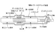
そのため図7のステアリング装置では、弾性材料からなり且つラック軸及びハウジングと同軸の環状をなす第一シール部材及び第二シール部材が、ハウジングの内周面の二箇所にそれぞれ固定されている。第一シール部材は、ラック軸のねじ溝とラック歯部との間に位置する円筒面である第一外周部に対してスライド自在に水密状態で接触している。一方、第二シール部材は、ラック軸のねじ溝を挟んでラック歯部と反対側に位置する円筒面である第二外周部に対してスライド自在に水密状態で接触している。 Therefore, in the steering device of FIG. 7, the first seal member and the second seal member, which are made of an elastic material and have an annular shape that is coaxial with the rack shaft and the housing, are respectively fixed at two locations on the inner peripheral surface of the housing. The first seal member is slidably in contact with the first outer peripheral portion which is a cylindrical surface located between the thread groove of the rack shaft and the rack tooth portion. On the other hand, the second seal member is slidably in contact with a second outer peripheral portion which is a cylindrical surface located on the opposite side of the rack tooth portion across the thread groove of the rack shaft.
ピニオンシャフトの回転力又は(及び)電動モータの回転力がラック軸に伝わることによりラック軸がハウジングに対して左右方向に移動すると、第一シール部材と第二シール部材とがラック軸の第一外周部と第二外周部とに対してそれぞれ摺動する。そして、ラック軸のハウジングに対する左右方向の相対位置に関らず、第一シール部材と第二シール部材はラック軸の第一外周部と第二外周部とに対してそれぞれ接触する。
従って、仮にハウジングの両端開口を通して水分がハウジング内に侵入しても、この水分が第一シール部材及び第二シール部材とラック軸の外周面との間を通り抜けてボールねじナットに塗布したグリースを洗い流してしまうおそれは小さい。
When the rotational force of the pinion shaft or the rotational force of the electric motor is transmitted to the rack shaft and the rack shaft moves in the left-right direction with respect to the housing, the first seal member and the second seal member are moved to the first of the rack shaft. Slide relative to the outer peripheral portion and the second outer peripheral portion. The first seal member and the second seal member are in contact with the first outer peripheral portion and the second outer peripheral portion of the rack shaft, respectively, regardless of the relative position in the left-right direction with respect to the housing of the rack shaft.
Therefore, even if moisture enters the housing through the openings at both ends of the housing, the moisture passes between the first seal member and the second seal member and the outer peripheral surface of the rack shaft and grease applied to the ball screw nut is applied. The risk of being washed away is small.
仮にラック軸の第一シール部材と第二シール部材が接触する部位(第一外周部及び第二外周部)に凹凸があると、第一シール部材及び第二シール部材とラック軸との間に隙間が形成され、この隙間を通して水分がボールねじナット側に向かうおそれがある。そのため、第一シール部材及び第二シール部材はラック軸の(凹凸のない)円筒面に対して接触させる必要がある。
さらにラック軸の左右方向移動に伴って第一外周部の第一シール部材に対する接触位置及び第二外周部の第二シール部材に対する接触位置は左右方向に変化する。そのため第一外周部及び第二外周部の左右方向長は、ラック軸の左右の移動限界位置間の距離(スライド可能距離)以上でなければならない。
If there are irregularities in the portion (first outer peripheral portion and second outer peripheral portion) where the first seal member and the second seal member of the rack shaft come into contact, the space between the first seal member and the second seal member and the rack shaft A gap is formed, and there is a possibility that moisture may go to the ball screw nut through the gap. Therefore, the first seal member and the second seal member need to be brought into contact with the cylindrical surface of the rack shaft (without unevenness).
Further, as the rack shaft moves in the left-right direction, the contact position of the first outer periphery with the first seal member and the contact position of the second outer periphery with the second seal member change in the left-right direction. Therefore, the length in the left-right direction of the first outer periphery and the second outer periphery must be equal to or greater than the distance between the left and right movement limit positions of the rack shaft (slidable distance).
しかし図7のステアリング装置のラック軸には、ピニオンシャフトと電動モータがそれぞれ接続するラック歯部とねじ溝が形成されている。さらにラック軸の全長(左右方向長)は、ステアリング装置が搭載される車両の車幅によって制限される。 However, the rack shaft of the steering device in FIG. 7 is formed with a rack tooth portion and a thread groove to which the pinion shaft and the electric motor are respectively connected. Furthermore, the total length (the length in the left-right direction) of the rack shaft is limited by the vehicle width of the vehicle on which the steering device is mounted.
そのため車幅が狭い車両に搭載されるラック軸の外周面に、ラック歯部及びねじ溝を形成し且つラック歯部及びねじ溝とは左右方向位置をずらしながら第一外周部及び第二外周部を形成するためには、ラック歯部、ねじ溝、第一外周部及び第二外周部の左右長を短くする必要がある。即ち、ラック歯部及びねじ溝の左右長を短くすることによりラック軸のスライド可能距離を短くし、これに合わせて第一外周部及び第二外周部の左右長を短くする必要がある。
しかしラック歯部及びねじ溝の左右長を短くすると、前輪の最大舵角が小さくなるので、車両の旋回性能が低下してしまう。
Therefore, a rack tooth portion and a screw groove are formed on the outer peripheral surface of a rack shaft mounted on a vehicle having a narrow vehicle width, and the first outer peripheral portion and the second outer peripheral portion are shifted in the left-right direction position with respect to the rack tooth portion and the screw groove. Therefore, it is necessary to shorten the left and right lengths of the rack tooth portion, the thread groove, the first outer peripheral portion, and the second outer peripheral portion. That is, it is necessary to shorten the rack shaft slidable distance by shortening the left and right lengths of the rack tooth portion and the thread groove, and to shorten the left and right lengths of the first outer peripheral portion and the second outer peripheral portion accordingly.
However, if the left and right lengths of the rack tooth portion and the thread groove are shortened, the maximum steering angle of the front wheels is reduced, so that the turning performance of the vehicle is deteriorated.
また、ラック軸を搭載する車両の車幅が狭い場合に前輪の最大舵角を大きめに設定すると、ラック軸の全長が短いにも拘わらずラック歯部及びねじ溝の左右長は長くなる。そのため、第一外周部及び第二外周部の左右長がラック軸のスライド可能距離より短くなってしまう。
この場合は、ラック軸がスライド動作を行うときに、第一シール部材と第二シール部材が凹凸形状であるラック歯部とねじ溝に対してそれぞれ接触してしまう。そのためこの場合は、第一シール部材及び第二シール部材とラック軸との間の隙間を通して水分がボールねじナット側に向かい、ボールねじナットのグリースが洗い流されてしまうおそれがある。
If the maximum steering angle of the front wheels is set to be large when the vehicle width of the vehicle on which the rack shaft is mounted is narrow, the left and right lengths of the rack tooth portion and the screw groove become long although the overall length of the rack shaft is short. Therefore, the left and right lengths of the first outer peripheral portion and the second outer peripheral portion are shorter than the slidable distance of the rack shaft.
In this case, when the rack shaft performs a sliding operation, the first seal member and the second seal member come into contact with the rack tooth portion and the thread groove, which are uneven. Therefore, in this case, moisture may flow toward the ball screw nut through the gap between the first seal member and the second seal member and the rack shaft, and the grease on the ball screw nut may be washed away.
本発明は、上述した課題に対処するためになされたものである。即ち、本発明の目的の1つは、ラック軸の全長が短く且つ車輪の最大舵角を大きめに設定した場合であっても、水分がハウジングの内部に設けられたボールねじナットに接触することを防止できるステアリング装置を提供することにある。 The present invention has been made to address the above-described problems. That is, one of the objects of the present invention is that moisture contacts the ball screw nut provided inside the housing even when the total length of the rack shaft is short and the maximum steering angle of the wheel is set to be large. It is an object of the present invention to provide a steering device that can prevent the above.
上記目的を達成するための本発明のステアリング装置は、
車体(11)の幅方向である左右方向に延びる筒状ハウジング(21)と、
前記ハウジング内に自身の軸線まわりに回転不能に挿入され、前記軸線方向にスライドすることにより車輪(15L、15R)の操舵角を変化させ且つ前記軸線方向の位置が互いに異なる二か所にラック歯部(32)とねじ溝(36)とが形成されたラック軸(30)と、
ステアリングホイール(53)の回転力を前記ラック歯部に伝えることにより前記ラック軸をスライドさせるピニオンシャフト(50)と、
前記ハウジングの内部に設けられ且つ電動モータ(44)の回転力を前記ねじ溝に伝えることにより前記ラック軸をスライドさせるボールねじナット(40)と、
前記ねじ溝より前記ラック歯部側において、前記ラック軸の外周面と前記ハウジングの内周面の一方に固定され且つ他方に形成された前記軸線を中心とする円筒面(26、33)にスライド自在に接触する第一シール部材(45)と、
前記ねじ溝を挟んで前記ラック歯部とは反対側において、前記ラック軸の外周面と前記ハウジングの内周面の前記他方に固定され且つ前記一方に形成された前記軸線を中心とする円筒面(27、37)にスライド自在に接触する第二シール部材(47)と、
を備える。
In order to achieve the above object, a steering apparatus according to the present invention comprises:
A cylindrical housing (21) extending in the left-right direction which is the width direction of the vehicle body (11);
The rack tooth is inserted into the housing in a non-rotatable manner around its own axis, and changes the steering angle of the wheels (15L, 15R) by sliding in the axial direction, and the rack teeth at two different positions in the axial direction. A rack shaft (30) formed with a portion (32) and a thread groove (36);
A pinion shaft (50) that slides the rack shaft by transmitting the rotational force of the steering wheel (53) to the rack tooth portion;
A ball screw nut (40) which is provided inside the housing and slides the rack shaft by transmitting the rotational force of the electric motor (44) to the thread groove;
On the rack tooth portion side of the thread groove, it is fixed to one of the outer peripheral surface of the rack shaft and the inner peripheral surface of the housing and slides on a cylindrical surface (26, 33) centered on the axis formed on the other. A first seal member (45) in free contact;
A cylindrical surface centered on the axis formed on the one side and fixed to the other of the outer peripheral surface of the rack shaft and the inner peripheral surface of the housing on the opposite side of the rack tooth portion across the screw groove A second seal member (47) slidably in contact with (27, 37);
Is provided.
本発明のステアリング装置では、ハウジングとラック軸との間をシールする二つのシール部材(第一シール部材、第二シール部材)の一方をラック軸の外周面に固定し、他方をハウジングの内周面に固定している。そのためラック軸の軸線方向移動に伴って、一方のシール部材はハウジングの内周面に形成された円筒面に対して摺動し、他方のシール部材はラック軸の外周面に形成された円筒面に対して摺動する。
このように他方のシール部材が摺動する摺動面のみをラック軸に形成し、一方のシール部材が摺動する摺動面をハウジングに形成している。換言すると、ラック軸の外周面にはラック歯部、ねじ溝及び他方のシール部材が摺動する円筒面のみを形成し、一方のシール部材が摺動する円筒面は形成しない。
そのためラック軸の全長が短い場合であっても、ラック軸にラック歯部、ねじ溝及び他方のシール部材が摺動する円筒面をそれぞれの全長を長くしながら形成することが可能である。
従って、ラック軸の全長が短く且つ車輪の最大舵角を大きめに設定した場合であっても、ハウジングの両端開口からハウジング内に侵入した水分がハウジングの内部に設けられたボールねじナットに接触することを防止できる。
In the steering device of the present invention, one of the two seal members (first seal member and second seal member) for sealing between the housing and the rack shaft is fixed to the outer peripheral surface of the rack shaft, and the other is fixed to the inner periphery of the housing. It is fixed to the surface. Therefore, as the rack shaft moves in the axial direction, one seal member slides on the cylindrical surface formed on the inner peripheral surface of the housing, and the other seal member is a cylindrical surface formed on the outer peripheral surface of the rack shaft. Slide against.
Thus, only the sliding surface on which the other seal member slides is formed on the rack shaft, and the sliding surface on which one seal member slides is formed on the housing. In other words, only the cylindrical surface on which the rack tooth portion, the thread groove, and the other seal member slide is formed on the outer peripheral surface of the rack shaft, and the cylindrical surface on which one seal member slides is not formed.
Therefore, even when the total length of the rack shaft is short, a cylindrical surface on which the rack tooth portion, the thread groove, and the other seal member slide can be formed on the rack shaft while increasing the total length.
Therefore, even when the rack shaft is short and the maximum steering angle of the wheel is set to be large, moisture that has entered the housing from both ends of the housing contacts the ball screw nut provided inside the housing. Can be prevented.
前記第一シール部材が、前記ラック軸の外周面に前記ラック歯部と前記ねじ溝との間に位置させて形成された第一外周部(33)に固定され且つ前記ハウジングの前記円筒面である第一内周部(26)に対してスライド自在に接触し、前記第二シール部材が、前記ハウジングの内周面に前記第一内周部とは位置をずらして形成された第二内周部(27)に固定され且つ前記ラック軸の外周面に前記ねじ溝を挟んで前記ラック歯部とは反対側に位置させて形成された前記円筒面である第二外周部(37)に対してスライド自在に接触してもよい。 The first seal member is fixed to a first outer peripheral portion (33) formed on the outer peripheral surface of the rack shaft so as to be positioned between the rack tooth portion and the screw groove, and on the cylindrical surface of the housing. A second inner member formed so as to be slidably contacted with a first inner peripheral portion (26), and wherein the second seal member is formed on the inner peripheral surface of the housing so as to be displaced from the first inner peripheral portion. A second outer peripheral portion (37) which is the cylindrical surface fixed to the peripheral portion (27) and formed on the outer peripheral surface of the rack shaft on the opposite side of the rack tooth portion with the screw groove interposed therebetween. You may contact slidably with respect.
車輪の最大舵角を大きめに設定しつつラック軸の第二外周部に第二シール部材を固定した場合は、第二シール部材が接触するハウジングの第二内周部を長めに形成する必要があるため、ハウジングの全長を長くしなければならない。しかし一般的に、車両においてはハウジングの周囲には様々な部材が設けられるため、これらの部材とハウジングとの干渉を回避しなければならい。そのためにはハウジングの全長を短くするために、第二内周部を短くしなければならない場合がある。しかしながらこの場合は、車輪の最大舵角を大きめに設定すると、車輪の舵角が最大舵角となったときに第二シール部材がハウジングの第二内周部以外の部位に接触してしまうおそれがある。即ち、車輪の舵角が最大舵角となったときに、第二シール部材がハウジングの第二内周部に接触しなくなり、その結果、水分がボールねじナットに接触するおそれがある。
しかし本発明をこのように構成した場合は、車輪の最大舵角を大きめに設定した場合であっても、第二シール部材が固定される第二内周部を長めに形成する必要がない。そのため、ハウジングの全長を短くしつつ車輪の最大舵角を大きめに設定した場合であっても、第二シール部材をラック軸の第二外周部に対して常に接触させることが可能になる。従って、車輪の舵角が最大舵角となったときに、水分がボールねじナットに接触することを防止できる。
When the second seal member is fixed to the second outer peripheral portion of the rack shaft while setting the maximum steering angle of the wheel to be large, the second inner peripheral portion of the housing that is in contact with the second seal member needs to be formed longer. For this reason, the total length of the housing must be increased. However, in general, since various members are provided around the housing in a vehicle, it is necessary to avoid interference between these members and the housing. For this purpose, the second inner peripheral portion may have to be shortened in order to shorten the overall length of the housing. However, in this case, if the maximum steering angle of the wheel is set to be large, the second seal member may come into contact with a portion other than the second inner peripheral portion of the housing when the steering angle of the wheel reaches the maximum steering angle. There is. That is, when the rudder angle of the wheel reaches the maximum rudder angle, the second seal member does not come into contact with the second inner peripheral portion of the housing, and as a result, there is a possibility that moisture contacts the ball screw nut.
However, when the present invention is configured in this way, even if the maximum steering angle of the wheel is set to be large, it is not necessary to form a long second inner peripheral portion to which the second seal member is fixed. Therefore, even when the maximum steering angle of the wheel is set to be large while shortening the overall length of the housing, the second seal member can always be brought into contact with the second outer peripheral portion of the rack shaft. Therefore, it is possible to prevent moisture from coming into contact with the ball screw nut when the steering angle of the wheel reaches the maximum steering angle.
前記ラック軸が、前記ねじ溝が形成された大径部(35)と、前記第一外周部が形成され且つ前記大径部より小径の小径部(31)と、を備え、前記第一シール部材の外径が前記大径部より大きく、前記ラック軸の前記ハウジングに対する相対位置が所定位置となったときに、前記大径部が前記第一内周部に対して内周側から対向してもよい。 The rack shaft includes a large-diameter portion (35) in which the thread groove is formed, and a small-diameter portion (31) in which the first outer peripheral portion is formed and having a smaller diameter than the large-diameter portion, and the first seal When the outer diameter of the member is larger than the large diameter portion and the relative position of the rack shaft to the housing is a predetermined position, the large diameter portion faces the first inner peripheral portion from the inner peripheral side. May be.
第一シール部材を第一外周部に固定し且つ第二シール部材を第二内周部に固定した場合は、第一内周部の第一シール部材より第二シール部材側に位置する部位とラック軸との間に形成された環状空間の容積(大きさ)V1が、ラック軸のハウジングに対する相対位置に応じて変化する。その一方で、ハウジングの第一内周部よりも第二シール部材側に位置する部位とラック軸との間に形成された環状空間の容積V0は、ラック軸のハウジングに対する相対位置が変化しても変わらない。
仮にラック軸のスライド動作に伴う容積V1の変化量ΔV1が大きい場合には、ラック軸のハウジングに対する相対位置が変化したときの第一シール部材と第二シール部材との間のハウジングとラック軸との間に形成された環状空間(以下、シール部材間空間と呼ぶ)の容積の変化率が大きくなる。換言すると、シール部材間空間における気圧の変化率が大きくなる。
仮にラック軸がスライド動作を行うときにシール部材間空間における気圧が大きく減少すると、第一シール部材及び第二シール部材の外側の空気や水分が、第一シール部材と第一外周部との間及び第二シール部材と第二内周部との間を通り抜けてシール部材間空間に吸い込まれ易くなる。
しかし、本発明をこのように構成した場合は、ラック軸のねじ溝が形成された部位の外径を第一外周部が形成された部位の外径以下とした場合と比べて、容積V1が小さくなる。そのため、ラック軸のスライド動作に伴う容積V1の変化量ΔV1も小さくなる。従って、ラック軸がスライド動作を行うときのシール部材間空間における気圧の変化率が小さくなる。従って、シール部材間空間の気圧を減少させる方向にラック軸がスライドしたときに、第一シール部材及び第二シール部材の外側の空気や水分が、第一シール部材と第一外周部との間及び第二シール部材と第二内周部との間を通り抜けてシール部材間空間に流れ込むおそれが小さくなる。
When the first seal member is fixed to the first outer peripheral portion and the second seal member is fixed to the second inner peripheral portion, a portion located on the second seal member side from the first seal member of the first inner peripheral portion; The volume (size) V1 of the annular space formed between the rack shaft and the rack shaft changes according to the relative position of the rack shaft with respect to the housing. On the other hand, the volume V0 of the annular space formed between the portion positioned closer to the second seal member than the first inner peripheral portion of the housing and the rack shaft changes the relative position of the rack shaft to the housing. Will not change.
If the change amount ΔV1 of the volume V1 due to the sliding movement of the rack shaft is large, the housing and the rack shaft between the first seal member and the second seal member when the relative position of the rack shaft to the housing changes. The rate of change in volume of the annular space (hereinafter referred to as the space between seal members) formed between the two increases. In other words, the rate of change of the atmospheric pressure in the space between the seal members is increased.
If the pressure in the space between the seal members is greatly reduced when the rack shaft performs a sliding operation, air and moisture outside the first seal member and the second seal member are between the first seal member and the first outer peripheral portion. And it becomes easy to be sucked into the space between seal members through between the second seal member and the second inner peripheral portion.
However, when the present invention is configured in this way, the volume V1 is smaller than the case where the outer diameter of the part where the thread groove of the rack shaft is formed is equal to or less than the outer diameter of the part where the first outer peripheral part is formed. Get smaller. For this reason, the change amount ΔV1 of the volume V1 accompanying the sliding operation of the rack shaft is also reduced. Therefore, the rate of change of the atmospheric pressure in the space between the seal members when the rack shaft performs the sliding operation is reduced. Therefore, when the rack shaft slides in a direction to reduce the air pressure in the space between the seal members, air and moisture outside the first seal member and the second seal member are between the first seal member and the first outer peripheral portion. In addition, the risk of passing through between the second seal member and the second inner peripheral portion and flowing into the space between the seal members is reduced.
前記ハウジングの一部が、前記第一シール部材と前記第二シール部材との間に位置し且つ隣接部に比べて径が大きい大径筒状部(22)によって構成されてもよい。 A part of the housing may be constituted by a large-diameter cylindrical portion (22) positioned between the first seal member and the second seal member and having a larger diameter than the adjacent portion.
このように構成すると容積V0が大きくなる。そのため、ラック軸のスライド動作に伴うシール部材間空間の容積の変化率が小さくなり、その結果、シール部材間空間における気圧の変化率が小さくなる。
従って、シール部材間空間の気圧を減少させる方向にラック軸がスライドしたときに、第一シール部材及び第二シール部材の外側の空気や水分が、第一シール部材と第一外周部との間及び第二シール部材と第二内周部との間を通り抜けてシール部材間空間に吸い込まれるおそれをより小さくできる。
If comprised in this way, the volume V0 will become large. Therefore, the rate of change of the volume of the space between the seal members accompanying the slide operation of the rack shaft is reduced, and as a result, the rate of change of the atmospheric pressure in the space between the seal members is reduced.
Therefore, when the rack shaft slides in a direction to reduce the air pressure in the space between the seal members, air and moisture outside the first seal member and the second seal member are between the first seal member and the first outer peripheral portion. In addition, the risk of passing through between the second seal member and the second inner peripheral portion and being sucked into the space between the seal members can be reduced.
前記大径筒状部の内部に前記ボールねじナットが設けられてもよい。 The ball screw nut may be provided inside the large-diameter cylindrical portion.
ハウジング内にボールねじナットを設けるためには、ハウジングを大径にする必要がある。その一方で、ハウジング全体を大径にすると、ハウジングの周囲に設けられる部材のレイアウトの自由度が低下してしまう。
しかし本発明をこのように構成すると、ハウジングの周囲に設けられる部材のレイアウトの自由度の低下を抑制しつつ、ハウジング内にボールねじナットを設けることが可能になる。
In order to provide the ball screw nut in the housing, the housing needs to have a large diameter. On the other hand, when the entire housing is made large in diameter, the degree of freedom in layout of members provided around the housing is lowered.
However, when the present invention is configured in this way, it is possible to provide a ball screw nut in the housing while suppressing a reduction in the degree of freedom of layout of members provided around the housing.
上記説明においては、発明の理解を助けるために、実施形態に対応する発明の構成に対して、実施形態で用いた符号を括弧書きで添えているが、発明の各構成要件は、前記符号によって規定される実施形態に限定されるものではない。
本発明の他の目的、他の特徴及び付随する利点は、以下の図面を参照しつつ記述される本発明の実施形態についての説明から容易に理解されるであろう。
In the above description, in order to help the understanding of the invention, the reference numerals used in the embodiments are attached to the configuration of the invention corresponding to the embodiments in parentheses, but each constituent element of the invention is represented by the reference numerals. It is not limited to the embodiments specified.
Other objects, other features and attendant advantages of the present invention will be readily understood from the description of the embodiments of the present invention described with reference to the following drawings.
以下、添付図面を参照しながら本発明の実施形態に係るステアリング装置について説明する。 Hereinafter, a steering apparatus according to an embodiment of the present invention will be described with reference to the accompanying drawings.
まずはステアリング装置を備える車両10の全体構造を図1を参照しながら簡単に説明する。
車両10の車体11の前部にはサスペンション(図示略)が設けられている。
周知のようにサスペンションは主な構成要素として、サスペンションメンバ、アッパーアーム、ロアアーム、キャリア、コイルスプリング及びショックアブゾーバ等を備えている。
左右のアッパーアームとロアアームとの先端部間には、それぞれキャリア(ナックルアーム)がキングピン軸まわりに回転可能として支持されている。左右のキャリアは前輪15L、15Rをそれぞれ水平軸まわりに回転可能に支持している。
First, the overall structure of the
A suspension (not shown) is provided at the front portion of the
As is well known, the suspension includes a suspension member, an upper arm, a lower arm, a carrier, a coil spring, a shock absorber, and the like as main components.
Carriers (knuckle arms) are supported between the tip portions of the left and right upper arms and the lower arms so as to be rotatable about the kingpin axis. The left and right carriers respectively support the
車両10の車体11の後部にもサスペンション(図示略)が設けられており、このサスペンションが左右の後輪16L、16Rをそれぞれ水平軸まわりに回転可能に支持している。
A suspension (not shown) is also provided at the rear portion of the
続いてステアリング装置20の詳しい構造について各図面を参照しながら説明する。
サスペンションメンバの上面には、車体11の幅方向、即ち左右方向に延びる筒状のハウジング21が固定されている。
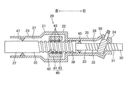
図示するようにハウジング21の長手方向の略中央部は、ハウジング21の中で最も内径が大きい略円筒状の大径筒状部22によって構成されている。ハウジング21の左側部23は大径筒状部22より小径の円筒部によって構成されている。ハウジング21の右端部24は大径筒状部22より小径且つ左側部23より大径の筒状部によって構成されている。ハウジング21の右端部24と大径筒状部22との間を構成する右側部25は、大径筒状部22及び左側部23と同軸をなし且つ左側部23より小径の円筒部により構成されている。さらに右側部25の内周面はハウジング21の軸線を中心とする(凹凸のない)円筒面からなる第一内周部26となっており、左側部23の内周面はハウジング21の軸線を中心とする(凹凸のない)円筒面からなる第二内周部27となっている。
Next, the detailed structure of the
A
As shown in the figure, the substantially central portion of the
ハウジング21の内部には、左右方向に延びる棒状部材であるラック軸30が同軸的に挿入されている。ラック軸30はハウジング21に対して左右方向にスライド可能且つ自身の軸線まわりに回転不能である。ラック軸30の左右両端部は、ハウジング21の左右両端の開口を通ってハウジング21の左右両側にそれぞれに位置している。
ラック軸30は小径部31と、小径部31から左側に延びる大径部35と、を同軸的に備えている。
小径部31の左右両端部を除く部分は円柱の一部を平面により切断した断面形状であり、その平面により切断された部位にはラック歯部32が形成されている。小径部31の左右両端部は互いに同軸をなす円柱形状であり、左端部の外周面はラック軸30の軸線を中心とする(凹凸のない)円筒面からなる第一外周部33により構成されている。
大径部35は小径部31と同軸をなす円柱形状であり、その外径は小径部31より大きく且つ右側部25の内径より僅かに小さい。大径部35の外周面にはねじ溝36が螺旋状に形成されている。さらに大径部35の外周面のねじ溝36より左側に位置する部位の外周面はラック軸30の軸線を中心とする(凹凸のない)円筒面からなる第二外周部37により構成されている。
A
The
A portion excluding the left and right end portions of the
The large-
図1に示すように、ラック軸30の左右両端部には左右一対のタイロッド18の内側端部が接続されており、左右のタイロッド18の外側端部は左右のキャリアに対してそれぞれ接続されている。
As shown in FIG. 1, the inner ends of a pair of left and
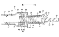
さらに図2に示すようにハウジング21の大径筒状部22の内部には、ねじ溝36の外周側に位置する回転ナット41が配設されている。回転ナット41はラック軸30と同軸の筒状部材であり、その内周面にはねじ溝42が螺旋状に形成されている。
さらにハウジング21の内部には、回転ナット41の外周側に位置する従動プーリ(図示略)が設けられている。この従動プーリは回転ナット41と同軸の筒状体であり、その内周面は回転ナット41の外周面に固定されている。従動プーリの外周面の一部には歯部が形成されている。
従動プーリの外周面の歯部とは異なる部位は、図示を省略した軸受を介して大径筒状部22の内周面に回転可能且つ左右方向にスライド不能に支持されている。従って、回転ナット41及び従動プーリは、ハウジング21に対してラック軸30の軸線まわりに相対回転可能である。
Further, as shown in FIG. 2, a rotating
Further, a driven pulley (not shown) located on the outer peripheral side of the
A portion different from the tooth portion on the outer peripheral surface of the driven pulley is supported on the inner peripheral surface of the large-diameter
さらにラック軸30のねじ溝36と回転ナット41のねじ溝42との間に形成された螺旋状の通路には複数のボール43が回転可能に挿入されている。
図示は省略してあるが、回転ナット41の内部にはねじ溝42の両端とそれぞれ連通し且つ各ボール43が移動可能な通路が形成されている。即ち、ねじ溝36とねじ溝42との間に形成された螺旋状の前記通路と、回転ナット41の内部に形成された当該通路と、により一つの環状通路が形成されている。従って、回転ナット41がラック軸30に対して相対回転すると、各ボール43が自転しながらこの環状通路内を循環する。
このように回転ナット41及びボール43が、ラック軸30と連係する周知のボールねじナット40を構成している。従って、回転ナット41がラック軸30に対して相対回転すると、ボール43を環状通路内で循環させながら、ラック軸30がハウジング21及び回転ナット41に対して左右方向にスライドする。
さらにボールねじナット40には、ボールねじナット40の回転動作を円滑にするためのグリース(図示略)が塗布されている。
Further, a plurality of
Although not shown, a passage is formed in the
Thus, the rotating
Further, grease (not shown) is applied to the
さらにハウジング21の大径筒状部22の外周面に固定された第一支持部材(図示略)には、電動モータ44が固定されている(図1参照)。さらに第一支持部材には、電動モータ44の周囲を覆う防水カバー(図示略)が設けられている。電動モータ44は、その本体部から突出する回転出力軸(図示略)を備えている。回転出力軸には駆動プーリ(図示略)が同軸的に固定されている。さらに図1に示すように、電動モータ44は制御装置60に接続されている。
Further, an
ハウジング21の大径筒状部22には第一貫通孔(図示略)が形成されている。
電動モータ44の駆動プーリ及び従動プーリには、環状をなし且つ内周面に歯部を有するベルト(図示略)が掛け回されており、ベルトの歯部が駆動プーリ及び従動プーリと噛み合っている。このベルトは、その一部が第一貫通孔を通してハウジング21内に位置しており、ハウジング21内において従動プーリと噛み合っている。
電動モータ44の駆動プーリが回転すると、この回転力がベルトを介して従動プーリに伝わり、従動プーリ及び回転ナット41が回転出力軸よりも遅い速度で回転する。
A first through hole (not shown) is formed in the large-diameter
A belt (not shown) having an annular shape and having a tooth portion on an inner peripheral surface is wound around the drive pulley and the driven pulley of the
When the drive pulley of the
ラック軸30の第一外周部33の外周面には、ラック軸30と同軸の環状体であり且つ弾性材料によって形成された第一シール部材45が固定されている。図2乃至図4に示すように、第一シール部材45の外径は大径部35よりも大きい。さらに第一シール部材45の外周部は、僅かに弾性変形した状態でハウジング21の第一内周部26に水密状態で接触している。さらに第一シール部材45は第一内周部26に対して摺動可能である。
一方、ハウジング21の第二内周部27には、ハウジング21と同軸の環状体であり且つ弾性材料によって形成された第二シール部材47が固定されている。図2乃至図4に示すように、第二シール部材47の内周部は僅かに弾性変形した状態でラック軸30の第二外周部37に水密状態で接触している。さらに第二シール部材47は第二外周部37に対して摺動可能である。
A
On the other hand, a
ハウジング21の右端部24には第二貫通孔(図示略)が形成されている。そしてこの第二貫通孔を介して、ピニオンシャフト50がハウジング21の内部に挿入されている。ピニオンシャフト50はハウジング21によって自身の軸線方向に相対移動不能に支持されている。ピニオンシャフト50は自身の軸線まわりに回転可能であり、ハウジング21の内部においてラック軸30のラック歯部32と噛み合っている。
図1に示すように、ピニオンシャフト50には、棒状部材であるステアリングシャフト51の一端(下端)がユニバーサルジョイント52を介して接続されている。さらにステアリングシャフト51の他端(上端)にはステアリングホイール53が固定されている。
従って、車両10に乗車しているドライバーがステアリングホイール53を回転させると、この回転力がステアリングシャフト51及びユニバーサルジョイント52を介してピニオンシャフト50に伝わり、ピニオンシャフト50が自身の軸線まわりに回転する。するとピニオンシャフト50と噛み合っているラック軸30がハウジング21に対して左右方向に相対スライドするので、タイロッド18及びキャリアを介してラック軸30と連係している前輪15L、15Rの舵角が変化する。
A second through hole (not shown) is formed in the
As shown in FIG. 1, one end (lower end) of a steering
Therefore, when a driver on the
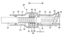
ステアリングホイール53の反時計方向の操舵角が最大操舵角となったときに、ラック軸30は図3に示すように左側の移動限界位置に位置する。このときラック軸30の大径部35(ねじ溝36)はハウジング21の右側部25(第一内周部26)より左側に位置する。
ステアリングホイール53の回転位置が、反時計方向の最大操舵角よりも時計方向側の位置になると、大径部35(ねじ溝36)の一部が右側部25(第一内周部26)の内周側に位置する。
さらにステアリングホイール53の時計方向の操舵角が最大操舵角となったときに、ラック軸30は図4に示すように右側の移動限界位置に位置する。このときラック軸30のねじ溝36の略右半分が右側部25(第一内周部26)の内周側に位置する。
When the counterclockwise steering angle of the
When the rotational position of the
Further, when the steering angle of the
さらに図1に示すようにハウジング21には、ピニオンシャフト50の操舵トルク(回転トルク)を検出するための操舵トルクセンサ55が設けられている。図1に示すように操舵トルクセンサ55は制御装置60に接続されている。
Further, as shown in FIG. 1, the
続いて、以上構成のステアリング装置20の動作及びこの動作に伴う車両10の動作について説明する。
車両10に乗車しているドライバーが手でステアリングホイール53を一方向に回転操作すると、ピニオンシャフト50が回転しラック軸30がハウジング21に対して左右方向の一方向に相対スライドするので、タイロッド18及びキャリアを介してラック軸30と連係している前輪15L、15Rの舵角が変化する。
Next, the operation of the
When a driver riding on the
さらにピニオンシャフト50が回転すると、操舵トルクセンサ55がピニオンシャフト50の回転転操作トルク(操舵トルク)を検出し、検出値を制御装置60へ送信する。すると、制御装置60が送信された回転操作トルクに応じた目標操舵アシストトルクを演算し、さらに目標操舵アシストトルクが得られるように電動モータ44を作動させる。
When the
すると、電動モータ44の回転出力軸及び駆動プーリが回転するので、駆動プーリと噛み合っているベルトが回転する。するとベルトの回転力が従動プーリを介して回転ナット41に伝わるので、回転ナット41がラック軸30に対して相対回転し、回転ナット41(ねじ溝42)の回転力がボール43を介してラック軸30(ねじ溝36)に伝達される。即ち、回転ナット41の回転力が、ステアリングホイール53によって一方向にスライドさせられたラック軸30を当該一方向にスライドさせるためのアシスト力としてラック軸30に伝達される。従って、ドライバーは大きな力をステアリングホイール53に付与することなく且つ前輪15L、15Rが所望の操舵角となるように、ラック軸30をスライドさせることが可能である。
Then, since the rotation output shaft of the
さらにハウジング21とラック軸30との間をシールする二つのシール部材の一方である第一シール部材45をラック軸30の第一外周部33に固定し、他方である第二シール部材47をハウジング21の第二内周部27に固定している。そしてラック軸30のハウジング21に対する左右方向移動に伴って、第一シール部材45はハウジング21の第一内周部26に対して摺動し、第二シール部材47はラック軸30の第二外周部37に対して摺動する。
Further, a
このように一方のシール部材(第二シール部材47)が摺動する円筒面(第二外周部37)のみをラック軸30に形成し、他方のシール部材(第一シール部材45)が摺動する円筒面(第一内周部26)をハウジング21に形成している。換言すると、ラック軸30の外周面にはラック歯部32、ねじ溝36及び第二シール部材47が摺動する第二外周部37が形成される一方で、第一シール部材45の摺動面である第一内周部26は形成されていない。また第一外周部33は第一シール部材45の左右長と同じ長さだけあれば足りるので、第一外周部33の左右長は短くすることが可能である。
そのためラック軸30の全長(左右方向長)が短い場合であっても、ラック軸30にラック歯部32、ねじ溝36及び第二シール部材47が摺動する第二外周部37を、それぞれの全長を長くしながら形成することが可能である。
従って、ラック軸30の全長が短く且つ前輪15L、15Rの最大舵角を大きめに設定した場合(即ち、ラック軸30の左右方向のスライド可能距離が長い場合)であっても、ハウジング21の左右両端開口からハウジング21内に侵入した水分がボールねじナット40側に向かうおそれは小さい。そのため、ボールねじナット40に塗布したグリースが水分によって洗い流され、その結果、ボールねじナット40の動作が不円滑になったり、ボールねじナット40の耐久性が低下したりするおそれは小さい。
Thus, only the cylindrical surface (second outer peripheral portion 37) on which one seal member (second seal member 47) slides is formed on the
Therefore, even if the total length (the length in the left-right direction) of the
Therefore, even when the
なお、前輪15L、15Rの最大舵角を大きめに設定しつつラック軸30の第二外周部37に第二シール部材47を固定する(且つハウジング21の第一内周部26に第一シール部材45を固定する)ことも可能である。この場合は、第二シール部材47が接触する第二内周部27を長めに形成する必要があるため、ハウジング21の全長を長くしなければならない。
但し、一般的に車両10のハウジング21周囲の空間には様々な部材が設けられるため、これらの部材との干渉を避けるためにハウジング21の全長を短くしなければならない場合がある。しかしながらハウジング21の全長を短くした場合は、前輪15L、15Rの反時計方向の舵角が最大舵角となったときに、第二シール部材47がハウジング21の左端部からハウジング21の外側に脱落するおそれがある。換言すると、前輪15L、15Rの反時計方向の舵角が最大舵角となったときに、第二シール部材47がハウジング21の第二内周部27に接触しなくなり、その結果、水分が第二内周部27とラック軸30との間の環状空間を通ってボールねじナット40へ向かうおそれがある。
The
However, since various members are generally provided in the space around the
しかし本実施形態のステアリング装置20のように第二シール部材47をハウジング21の第二内周部27に固定した場合は、前輪15L、15Rの最大舵角を大きめに設定した場合であっても、第二シール部材47を固定する第二内周部27を長めに形成する必要がない。そのため、ハウジング21の全長を短くしつつ前輪15L、15Rの最大舵角を大きめに設定した場合(即ち、ラック軸30の左右方向のスライド可能距離を長めに設定した場合)であっても、第二シール部材47をラック軸30の第二外周部37に対して常に接触させることが可能である。
従って、前輪15L、15Rの舵角が最大舵角となったときに、第二シール部材47とラック軸30の第二外周部37との間を通って水分がボールねじナット40側に向かうおそれは小さい。
However, when the
Therefore, when the steering angle of the
さらに図5及び図6は比較例のステアリング装置20’を示している。このステアリング装置20’ではラック軸30’の外径はその全長に渡って略一定である。換言するとラック軸30’はラック軸30の小径部31と大径部35に対応する構成を備えていない。
5 and 6 show a steering device 20 'of a comparative example. In the steering device 20 ', the outer diameter of the rack shaft 30' is substantially constant over its entire length. In other words, the
ステアリング装置20では、第一内周部26の左端部と第一シール部材45が接触する位置との間の部位とラック軸30との間に形成された環状空間の容積V1は、ラック軸30のハウジング21に対する相対位置に応じて変化する。同様にステアリング装置20’においても、第一内周部26の左端部と第一シール部材45が接触する位置との間の部位とラック軸30との間に形成された環状空間の容積V1’は、ラック軸30のハウジング21に対する相対位置に応じて変化する。その一方で、いずれのステアリング装置20、20’においてもハウジング21の内周面の第一内周部26の左端部と第二シール部材47との間に位置する部位とラック軸30との間に形成された環状空間の容積V0は、ラック軸30、30’のハウジング21に対する相対位置が変化しても一定である。
In the
図5はステアリング装置20’のラック軸30’が左側の移動限界位置に位置する場合を示しており、図6はステアリング装置20’のラック軸30’が右側の移動限界位置に位置する場合を示している。
図5のときステアリング装置20’の容積V1’は最少値V1a’であり、図6のときステアリング装置20’の容積V1’は最大値V1b’となり、図5と図6の間の容積V1’の変化量はΔV1’(=V1b’−V1a’)である。
ラック軸30’の外径はその全長に渡って略一定である。換言すると、ラック軸30’のねじ溝36が形成された部位の外径は、第一外周部33が形成された部位の外径より大きくない。そのため、ステアリング装置20’の第一内周部26とラック軸30’(第一外周部33、ねじ溝36)との間に形成される環状空間の断面積A’は大きくなる。従って、図5と図6の間の容積V1’の変化量ΔV1’は大きい値となる。そのため、ラック軸30’が左右の移動限界位置の間を移動するときの第一シール部材45と第二シール部材47との間のハウジング21とラック軸30’との間に形成された環状空間(シール部材間空間)の容積の変化率(=ΔV1’/(V0+V1a’))は大きくなる。換言すると、シール部材間空間における気圧の変化率が大きくなる。
仮にラック軸30’のスライド動作に伴ってシール部材間空間における気圧が大きく減少すると、第一シール部材45及び第二シール部材47の外側の空気や水分が、第一シール部材45と第一内周部26との間及び第二シール部材47と第二外周部37との間を通り抜けてシール部材間空間に吸い込まれ易くなる。即ち、水分によってボールねじナット40に塗布したグリースが洗い流されるおそれが大きくなる。
FIG. 5 shows a case where the
In FIG. 5, the volume V1 ′ of the
The outer diameter of the rack shaft 30 'is substantially constant over its entire length. In other words, the outer diameter of the part where the
If the air pressure in the space between the seal members is greatly reduced as the rack shaft 30 'slides, the air and moisture outside the
これに対して本実施形態のステアリング装置20では、ラック軸30のねじ溝36が形成された部位である大径部35の外径が、ラック歯部32が形成された部位である小径部31よりも大きい。そのため、ラック軸30が左側の移動限界位置(図3の位置)と右側の移動限界位置(図4の位置)と間で移動するときのステアリング装置20の第一内周部26とラック軸30(大径部35)との間に形成される環状空間の断面積Aは断面積A’より小さくなる。従って、図3と図4の間の容積V1の変化量ΔV1は変化量ΔV1’より小さくなる。そのため、ラック軸30が左右の移動限界位置の間を移動するときのシール部材間空間の容積の変化率(=ΔV1/(V0+V1a)。なお、図3におけるV1がV1aである)はステアリング装置20’と比べて小さくなり、ステアリング装置20のシール部材間空間における気圧の変化率はステアリング装置20’よりも小さくなる。
従って、ステアリング装置20のシール部材間空間の気圧を減少させる方向にラック軸30がスライドしたときに、第一シール部材45及び第二シール部材47の外側の空気や水分が、第一シール部材45と第一内周部26との間及び第二シール部材47と第二外周部37との間を通り抜けてシール部材間空間に吸い込まれ難い。即ち、水分によってボールねじナット40に塗布したグリースが洗い流されるおそれは小さい。
On the other hand, in the
Therefore, when the
さらにステアリング装置20のハウジング21の第一シール部材45と第二シール部材47との間に位置する部位には、隣接部に比べて内径が大きい大径筒状部22が形成されている。即ち、ハウジング21の内周面の第一内周部26の左端部と第二シール部材47との間に位置する部位とラック軸30との間に形成された環状空間の容積V0は、大径筒状部22が形成されていない場合と比べて大きい。
そのためステアリング装置20におけるラック軸30が左右の移動限界位置の間を移動するときのシール部材間空間の容積の変化率(=ΔV1/(V0+V1a)は、ハウジング21に大径筒状部22が形成されていない場合と比べて小さい。
従って、ステアリング装置20は大径筒状部22が形成されていない場合と比べて、水分や空気が第一シール部材45と第一内周部26との間及び第二シール部材47と第二外周部37との間を通り抜けてシール部材間空間に吸い込まれ難い。
Further, a large-diameter
Therefore, the volume change rate (= ΔV1 / (V0 + V1a) of the space between the seal members when the
Accordingly, in the
さらに、ハウジング21内にボールねじナット40を設けるためには、ハウジング21を大径にする必要がある。その一方で、ハウジング21全体を大径にすると、ハウジング21の周囲に設けられる部材のレイアウトの自由度が低下してしまう。
しかし本実施形態のハウジング21は、ボールねじナット40を設ける部位である大径筒状部22の径を大きくする一方で、大径筒状部22に隣接する左側部23及び右側部25の径を小さくしている。
そのため、ハウジング21の周囲に設けられる部材のレイアウトの自由度の低下を抑制しつつ、ハウジング21内にボールねじナット40を設けることを可能にしている。
Furthermore, in order to provide the
However, the
Therefore, it is possible to provide the
以上、本発明を上記各実施形態に基づいて説明したが、本発明は上記実施形態に限定されるものではなく、本発明の目的を逸脱しない限りにおいて種々の変更が可能である。
例えば、ハウジング21の第一内周部26に固定した第一シール部材(上記実施形態の第二シール部材47と同一構造のシール部材)をラック軸30の第一外周部33に摺動可能に接触させ且つラック軸30の第二外周部37に固定した第二シール部材(上記実施形態の第一シール部材45と同一構造のシール部材)をハウジング21の第二内周部27に摺動可能に接触させてもよい。
As mentioned above, although this invention was demonstrated based on said each embodiment, this invention is not limited to the said embodiment, A various change is possible unless it deviates from the objective of this invention.
For example, a first seal member (seal member having the same structure as the
ハウジング21に左側から順番に右端部24、第一内周部26、大径筒状部22及び第二内周部27を形成し、且つ、ラック軸30に左側から順番にラック歯部32、第一外周部33、ねじ溝36及び第二外周部37を形成してもよい。
A
ラック軸30に小径部31と大径部35を設けずに、ラック軸30の外径を全長に渡って略一定にしてもよい。
The outer diameter of the
20・・・ステアリング装置、21・・・ハウジング、22・・・大径筒状部、26・・・第一内周部、27・・・第二内周部、30・・・ラック軸、31・・・小径部、32・・・ラック歯部、33・・・第一外周部、35・・・大径部、36・・・ねじ溝、37・・・第二外周部、40・・・ボールねじナット、41・・・回転ナット、42・・・ねじ溝、43・・・ボール、44・・・電動モータ、45・・・第一シール部材、47・・・第二シール部材、50・・・ピニオンシャフト。
DESCRIPTION OF
Claims (5)
前記ハウジング内に自身の軸線まわりに回転不能に挿入され、前記軸線方向にスライドすることにより車輪の操舵角を変化させ且つ前記軸線方向の位置が互いに異なる二か所にラック歯部とねじ溝とが形成されたラック軸と、
ステアリングホイールの回転力を前記ラック歯部に伝えることにより前記ラック軸をスライドさせるピニオンシャフトと、
前記ハウジングの内部に設けられ且つ電動モータの回転力を前記ねじ溝に伝えることにより前記ラック軸をスライドさせるボールねじナットと、
前記ねじ溝より前記ラック歯部側において、前記ラック軸の外周面と前記ハウジングの内周面の一方に固定され且つ他方に形成された前記軸線を中心とする円筒面にスライド自在に接触する第一シール部材と、
前記ねじ溝を挟んで前記ラック歯部とは反対側において、前記ラック軸の外周面と前記ハウジングの内周面の前記他方に固定され且つ前記一方に形成された前記軸線を中心とする円筒面にスライド自在に接触する第二シール部材と、
を備える、
ステアリング装置。 A cylindrical housing extending in the left-right direction, which is the width direction of the vehicle body,
A rack tooth portion and a thread groove are inserted into the housing in a non-rotatable manner around its own axis, and changes the steering angle of the wheel by sliding in the axial direction and the positions in the axial direction are different from each other. Rack shaft formed with,
A pinion shaft that slides the rack shaft by transmitting a rotational force of a steering wheel to the rack tooth portion;
A ball screw nut that is provided inside the housing and slides the rack shaft by transmitting the rotational force of the electric motor to the thread groove;
The rack tooth portion side of the screw groove is fixed to one of the outer peripheral surface of the rack shaft and the inner peripheral surface of the housing and slidably contacts a cylindrical surface centered on the axis formed on the other. A seal member;
A cylindrical surface centered on the axis formed on the one side and fixed to the other of the outer peripheral surface of the rack shaft and the inner peripheral surface of the housing on the opposite side of the rack tooth portion across the screw groove A second seal member slidably in contact with,
Comprising
Steering device.
前記第一シール部材が、前記ラック軸の外周面に前記ラック歯部と前記ねじ溝との間に位置させて形成された第一外周部に固定され且つ前記ハウジングの前記円筒面である第一内周部に対してスライド自在に接触し、
前記第二シール部材が、前記ハウジングの内周面に前記第一内周部とは位置をずらして形成された第二内周部に固定され且つ前記ラック軸の外周面に前記ねじ溝を挟んで前記ラック歯部とは反対側に位置させて形成された前記円筒面である第二外周部に対してスライド自在に接触する、
ステアリング装置。 The steering apparatus according to claim 1, wherein
The first seal member is fixed to a first outer peripheral portion formed on the outer peripheral surface of the rack shaft so as to be positioned between the rack tooth portion and the thread groove, and is a first cylindrical surface of the housing. Slidably contact the inner periphery,
The second seal member is fixed to a second inner peripheral portion formed on the inner peripheral surface of the housing so as to be displaced from the first inner peripheral portion, and the screw groove is sandwiched between the outer peripheral surfaces of the rack shaft. And slidably contact the second outer peripheral portion which is the cylindrical surface formed on the opposite side to the rack tooth portion,
Steering device.
前記ラック軸が、前記ねじ溝が形成された大径部と、前記第一外周部が形成され且つ前記大径部より小径の小径部と、を備え、
前記第一シール部材の外径が前記大径部より大きく、
前記ラック軸の前記ハウジングに対する相対位置が所定位置となったときに、前記大径部が前記第一内周部に対して内周側から対向する、
ステアリング装置。 The steering apparatus according to claim 2, wherein
The rack shaft includes a large-diameter portion in which the thread groove is formed, and a small-diameter portion in which the first outer peripheral portion is formed and having a smaller diameter than the large-diameter portion,
The outer diameter of the first seal member is larger than the large diameter portion,
When the relative position of the rack shaft with respect to the housing is a predetermined position, the large-diameter portion faces the first inner peripheral portion from the inner peripheral side;
Steering device.
前記ハウジングの一部が、前記第一シール部材と前記第二シール部材との間に位置し且つ隣接部に比べて径が大きい大径筒状部によって構成された、
ステアリング装置。 The steering apparatus according to any one of claims 1 to 3,
A part of the housing is located between the first seal member and the second seal member, and is configured by a large-diameter cylindrical portion having a larger diameter than the adjacent portion.
Steering device.
前記大径筒状部の内部に前記ボールねじナットが設けられた、
ステアリング装置。
The steering apparatus according to claim 4, wherein
The ball screw nut is provided inside the large-diameter cylindrical portion,
Steering device.
Priority Applications (3)
| Application Number | Priority Date | Filing Date | Title |
|---|---|---|---|
| JP2016007983A JP6705653B2 (en) | 2016-01-19 | 2016-01-19 | Steering device |
| US15/409,043 US10124824B2 (en) | 2016-01-19 | 2017-01-18 | Steering apparatus |
| CN201710044001.XA CN107031712B (en) | 2016-01-19 | 2017-01-19 | steering device |
Applications Claiming Priority (1)
| Application Number | Priority Date | Filing Date | Title |
|---|---|---|---|
| JP2016007983A JP6705653B2 (en) | 2016-01-19 | 2016-01-19 | Steering device |
Publications (2)
| Publication Number | Publication Date |
|---|---|
| JP2017128182A true JP2017128182A (en) | 2017-07-27 |
| JP6705653B2 JP6705653B2 (en) | 2020-06-03 |
Family
ID=59313571
Family Applications (1)
| Application Number | Title | Priority Date | Filing Date |
|---|---|---|---|
| JP2016007983A Active JP6705653B2 (en) | 2016-01-19 | 2016-01-19 | Steering device |
Country Status (3)
| Country | Link |
|---|---|
| US (1) | US10124824B2 (en) |
| JP (1) | JP6705653B2 (en) |
| CN (1) | CN107031712B (en) |
Cited By (1)
| Publication number | Priority date | Publication date | Assignee | Title |
|---|---|---|---|---|
| WO2023053872A1 (en) * | 2021-09-28 | 2023-04-06 | Ntn株式会社 | Feed screw mechanism and electric actuator |
Families Citing this family (2)
| Publication number | Priority date | Publication date | Assignee | Title |
|---|---|---|---|---|
| JP7145014B2 (en) * | 2018-09-11 | 2022-09-30 | 日立Astemo株式会社 | steering device |
| US10822028B2 (en) * | 2018-10-03 | 2020-11-03 | Ford Global Technologies, Llc | Steering system with drag link |
Family Cites Families (12)
| Publication number | Priority date | Publication date | Assignee | Title |
|---|---|---|---|---|
| US4415054A (en) * | 1982-08-05 | 1983-11-15 | Trw Inc. | Steering gear |
| US4742882A (en) * | 1986-03-12 | 1988-05-10 | Honda Giken Kogyo Kabushiki Kaisha | Motor-driven power steering device |
| JPH05472Y2 (en) * | 1986-10-09 | 1993-01-07 | ||
| JPH0427743Y2 (en) * | 1986-10-27 | 1992-07-03 | ||
| GB2275901B (en) * | 1993-03-08 | 1996-07-24 | Honda Motor Co Ltd | Electrically operated power steering apparatus |
| DE10336628A1 (en) * | 2003-08-05 | 2005-03-24 | Thyssenkrupp Presta Steertec Gmbh | Steering gear for a motor vehicle |
| JP4351583B2 (en) * | 2004-05-21 | 2009-10-28 | 株式会社日立製作所 | Power steering device |
| JP2006256528A (en) | 2005-03-18 | 2006-09-28 | Favess Co Ltd | Seal structure, rotary shaft supporting device, and electric power steering device |
| KR100651141B1 (en) * | 2005-10-24 | 2006-11-29 | 주식회사 만도 | Electrically-assisted power steering apparatus |
| DE102006021863B4 (en) * | 2006-05-09 | 2009-02-19 | Zf Friedrichshafen Ag | Joint arrangement for a vehicle |
| JP2012017094A (en) | 2010-06-11 | 2012-01-26 | Honda Motor Co Ltd | Electric power steering device |
| JP2014234102A (en) | 2013-06-04 | 2014-12-15 | 株式会社ジェイテクト | Steering device |
-
2016
- 2016-01-19 JP JP2016007983A patent/JP6705653B2/en active Active
-
2017
- 2017-01-18 US US15/409,043 patent/US10124824B2/en active Active
- 2017-01-19 CN CN201710044001.XA patent/CN107031712B/en not_active Expired - Fee Related
Cited By (1)
| Publication number | Priority date | Publication date | Assignee | Title |
|---|---|---|---|---|
| WO2023053872A1 (en) * | 2021-09-28 | 2023-04-06 | Ntn株式会社 | Feed screw mechanism and electric actuator |
Also Published As
| Publication number | Publication date |
|---|---|
| US10124824B2 (en) | 2018-11-13 |
| US20170203783A1 (en) | 2017-07-20 |
| CN107031712B (en) | 2019-03-26 |
| CN107031712A (en) | 2017-08-11 |
| JP6705653B2 (en) | 2020-06-03 |
Similar Documents
| Publication | Publication Date | Title |
|---|---|---|
| US9897148B2 (en) | Reducer of electric power-assisted steering apparatus | |
| JP2017081515A (en) | Steering device of vehicle | |
| US10378639B2 (en) | Reducer of electric power steering apparatus | |
| US10046794B2 (en) | Rack assist type electric power steering apparatus | |
| JP6374782B2 (en) | Steering device for vehicle | |
| US9643644B2 (en) | Actuator and vehicle steering device | |
| KR20110062628A (en) | Steer by wire apparatus | |
| JP2017128182A (en) | Steering device | |
| WO2015129313A1 (en) | Power steering device and method for manufacturing ball screw for power steering device | |
| JP6990325B2 (en) | Steering device | |
| US20190168799A1 (en) | Steering system | |
| JP2018138421A (en) | Steering device | |
| CN107458454A (en) | Ball-screw apparatus and transfer | |
| JP2006218980A (en) | Steering gear for vehicle | |
| JP6790778B2 (en) | Steering device | |
| KR20170010522A (en) | Rack Assist Type Power Steering Apparatus | |
| JP2020075638A (en) | Steering unit | |
| JP2019147536A (en) | Steering device | |
| JP2015009632A (en) | Wheel steering device | |
| WO2017014181A1 (en) | Steering device and vehicle | |
| JP6111737B2 (en) | Electric power steering device | |
| JP2018138422A (en) | Steering device | |
| JP6890510B2 (en) | Power steering device | |
| JP6508100B2 (en) | Electric power steering device | |
| JP2018070073A (en) | Steering device |
Legal Events
| Date | Code | Title | Description |
|---|---|---|---|
| A621 | Written request for application examination |
Free format text: JAPANESE INTERMEDIATE CODE: A621 Effective date: 20181213 |
|
| A977 | Report on retrieval |
Free format text: JAPANESE INTERMEDIATE CODE: A971007 Effective date: 20191011 |
|
| A131 | Notification of reasons for refusal |
Free format text: JAPANESE INTERMEDIATE CODE: A131 Effective date: 20191023 |
|
| A521 | Request for written amendment filed |
Free format text: JAPANESE INTERMEDIATE CODE: A523 Effective date: 20191220 |
|
| TRDD | Decision of grant or rejection written | ||
| A01 | Written decision to grant a patent or to grant a registration (utility model) |
Free format text: JAPANESE INTERMEDIATE CODE: A01 Effective date: 20200421 |
|
| A61 | First payment of annual fees (during grant procedure) |
Free format text: JAPANESE INTERMEDIATE CODE: A61 Effective date: 20200514 |
|
| R151 | Written notification of patent or utility model registration |
Ref document number: 6705653 Country of ref document: JP Free format text: JAPANESE INTERMEDIATE CODE: R151 |
|
| R250 | Receipt of annual fees |
Free format text: JAPANESE INTERMEDIATE CODE: R250 |